EP1320426B1 - Press brake tooling with hardened surfaces - Google Patents
Press brake tooling with hardened surfaces Download PDFInfo
- Publication number
- EP1320426B1 EP1320426B1 EP01977870A EP01977870A EP1320426B1 EP 1320426 B1 EP1320426 B1 EP 1320426B1 EP 01977870 A EP01977870 A EP 01977870A EP 01977870 A EP01977870 A EP 01977870A EP 1320426 B1 EP1320426 B1 EP 1320426B1
- Authority
- EP
- European Patent Office
- Prior art keywords
- die
- punch
- nitrocarburized
- press brake
- groove
- Prior art date
- Legal status (The legal status is an assumption and is not a legal conclusion. Google has not performed a legal analysis and makes no representation as to the accuracy of the status listed.)
- Revoked
Links
- 238000005452 bending Methods 0.000 claims abstract description 20
- 229910000831 Steel Inorganic materials 0.000 claims abstract description 10
- 239000010959 steel Substances 0.000 claims abstract description 10
- 230000013011 mating Effects 0.000 claims abstract description 3
- 230000037228 dieting effect Effects 0.000 abstract 1
- 238000000034 method Methods 0.000 description 21
- 238000005121 nitriding Methods 0.000 description 14
- IJGRMHOSHXDMSA-UHFFFAOYSA-N Atomic nitrogen Chemical compound N#N IJGRMHOSHXDMSA-UHFFFAOYSA-N 0.000 description 8
- 238000006748 scratching Methods 0.000 description 7
- 230000002393 scratching effect Effects 0.000 description 7
- 238000012360 testing method Methods 0.000 description 5
- 229910052757 nitrogen Inorganic materials 0.000 description 4
- 150000002500 ions Chemical class 0.000 description 2
- 239000007788 liquid Substances 0.000 description 2
- 239000000463 material Substances 0.000 description 2
- 150000004767 nitrides Chemical class 0.000 description 2
- 150000003839 salts Chemical class 0.000 description 2
- OKTJSMMVPCPJKN-UHFFFAOYSA-N Carbon Chemical compound [C] OKTJSMMVPCPJKN-UHFFFAOYSA-N 0.000 description 1
- 229910000760 Hardened steel Inorganic materials 0.000 description 1
- 238000005299 abrasion Methods 0.000 description 1
- 230000006978 adaptation Effects 0.000 description 1
- 229910052799 carbon Inorganic materials 0.000 description 1
- 238000000576 coating method Methods 0.000 description 1
- 230000000295 complement effect Effects 0.000 description 1
- 150000001875 compounds Chemical class 0.000 description 1
- 150000001913 cyanates Chemical class 0.000 description 1
- 230000000994 depressogenic effect Effects 0.000 description 1
- 238000009792 diffusion process Methods 0.000 description 1
- 238000005516 engineering process Methods 0.000 description 1
- 230000006698 induction Effects 0.000 description 1
- 229910000765 intermetallic Inorganic materials 0.000 description 1
- 239000002184 metal Substances 0.000 description 1
- 238000012986 modification Methods 0.000 description 1
- 230000004048 modification Effects 0.000 description 1
- 150000002825 nitriles Chemical class 0.000 description 1
- QJGQUHMNIGDVPM-UHFFFAOYSA-N nitrogen group Chemical group [N] QJGQUHMNIGDVPM-UHFFFAOYSA-N 0.000 description 1
- 238000001556 precipitation Methods 0.000 description 1
- MNWBNISUBARLIT-UHFFFAOYSA-N sodium cyanide Chemical compound [Na+].N#[C-] MNWBNISUBARLIT-UHFFFAOYSA-N 0.000 description 1
- LIXWSNVLHFNXAJ-UHFFFAOYSA-N sodium;oxidoazaniumylidynemethane Chemical compound [Na+].[O-][N+]#[C-] LIXWSNVLHFNXAJ-UHFFFAOYSA-N 0.000 description 1
- 239000006104 solid solution Substances 0.000 description 1
- 238000005728 strengthening Methods 0.000 description 1
Images

Classifications
-
- B—PERFORMING OPERATIONS; TRANSPORTING
- B21—MECHANICAL METAL-WORKING WITHOUT ESSENTIALLY REMOVING MATERIAL; PUNCHING METAL
- B21D—WORKING OR PROCESSING OF SHEET METAL OR METAL TUBES, RODS OR PROFILES WITHOUT ESSENTIALLY REMOVING MATERIAL; PUNCHING METAL
- B21D5/00—Bending sheet metal along straight lines, e.g. to form simple curves
- B21D5/02—Bending sheet metal along straight lines, e.g. to form simple curves on press brakes without making use of clamping means
- B21D5/0209—Tools therefor
Definitions
- the present invention relates to press brake tooling according to the preamble of claim 1 (see for example JP-A-08 052 515).
- Press brake tooling comprises a punch having an elongated edge which is generally "V" shaped in cross section, and a die having an elongated groove which has a complementary V-shaped cross sectional configuration.
- the upwardly open V-shaped groove of the die terminates upwardly in a pair of spaced edges.
- the sliding motion between the bottom surface of the work piece and the surfaces of the spaced edges of the die can cause substantial damage to the spaced edges of the die.
- the rate of wear of the die accelerates, and when the die surface is damaged to the point that the workpiece is affected, of course, the die must be replaced.
- die surfaces have been hardened so as to resist scratching, pitting or wear.
- the hardening of these surfaces due to the methods of hardening, has been continued deep into the surfaces.
- press brake dies Two basic methods have been used to harden the surfaces of press brake dies.
- One of these methods involves making the entire die out of a tempered steel piece, but the resulting die is susceptible to breakage during use.
- the second method involves a heat hardening method, such as flame hardening or induction hardening, in which the surfaces of the die are hardened generally down to a depth of 1/8" or more in order to achieve the desired surface hardness. This is a somewhat long and expensive process and produces only fair results.
- the invention provides a press brake tooling according to claim 1.
- the surfaces of the die which are subjected to a rubbing or sliding action by the work piece can be nitrided or nitrocarburized to a small depth, generally not greater than about 1,52 mm (0.06 inches), and that the resulting tool is highly resistant to scratching, pitting or wear.
- This surprising result appears to be due not only to the superior hardness that is provided by the nitriding and nitrocarburizing processes, but particularly to the slipperiness that these processes provide.
- the smooth, lubricious surface of the spaced die edge surfaces enable work pieces to slide more easily across these surfaces in a bending operation.
- the surfaces accordingly are highly resistant to scratching, pitting or wear or other deformation, and provide dies having a long life. The frequency of repair or replacement of dies can thereby be significantly reduced.
- the present invention provides press brake tooling comprising a die and a mating punch for bending sheet stock, the punch having an elongated, generally V-shaped punch tip and the die being of steel and having an elongated, generally V-shaped groove in which the punch tip is received during a bending operation.
- the groove in the die has a floor and side walls extending divergently from the floor and terminating in edges spaced from each other across the width of the groove. The edges have edge surfaces that are configured to slidingly encounter the surface of a work piece as it is bent between the tool and the die.
- the die edge surfaces are nitrided or nitrocarburized to have a hardness in the range of 52 - 70 Rockwell C (that is, 86 to 94 on a 15-N microhardness scale), with said hardness extending into the die to a depth not exceeding about 0.06 inches.
- At least the edge surfaces of the die are thus nitrided or nitrocarburized, and desirably nitriding or nitrocarburizing is performed, if not on the entire die, at least that portion of the die including the spaced edge surfaces and the floor and walls of the V-shaped groove.
- the nitriding and nitrocarburizing processes provide a hardness of 52 - 70 Rockwell C (86 - 94 on a 15-N microhardness scale to a depth not exceeding about 0.06 inches and preferably not greater than about 0.03 inches.
- Plasma or ion nitriding involves the use of glow discharge technology to provide nascent nitrogen to the surface of a heated steel part.
- the part is subjected to a nitrogen plasma in a vacuum chamber.
- Liquid nitriding involves immersing a steel part in a molten, nitrogen-containing fused salt bath containing cyanides or cyanates, e.g., NaCN or NaCNO.
- a steel or tempered steel press brake die is formed having smooth, spaced upper edge surfaces on either side of its groove, and either the edge surfaces of the die to be contacted by a workpiece, or these surfaces together with the upwardly divergent walls forming the V-shaped grove, or even larger portions or all of the tool, can be subjected to a selected nitriding or nitrocarburizing process. What is important here is that the spaced edge surfaces of the tool that encounter in a sliding fashion the work piece during a bending operation be subjected to the nitriding or nitrocarburizing process.
- a die of the invention is shown generally as 10, a complimentary shaped punch is shown as 12, and a work piece as 14.
- the die has an upwardly open groove, 16, having a floor 18, and upwardly diverging walls, 20, as depicted, terminating in spaced die edges 22.
- the floor 18 may be the intersection of the upwardly divergent walls 20, or may be slightly rounded or slightly flattened, both for the purpose of avoiding stress concentration.
- the edge 22 has a generally rounded edge surface 24 over which the work piece 14 slides during a bending operation.
- the groove 16 formed by the walls 20 may have an included angle ranging from 30 to 120 degrees, with each of the groove walls 20 being oriented at from 15 to 60 degrees to the vertical. Dies having included angles of about 90 degrees are common.
- the upper tool 12 is provided with a similar V-shape, as shown in Figures 1 and 2.
- Arrow A in Figures 1 and 2 designate the direction of travel of the tool with respect to the die during a bending operation. If the included angle between the walls 20 of the die groove is assumed to be 90 degrees with each wall oriented to the vertical at a 45 degree angle, then simple mathematics shows that as the work piece is depressed completely into the groove by a distance (measured vertically) of one unit of length, it slides against the edge surface 24 over a length of about 0.4 units of length. The majority of the sliding action of the work piece across the edge surface 24 occurs after the work piece has reached the halfway mark in its vertical descent toward the floor 18 of the groove.
- the area of the edge surface contacted in a sliding, abrasive fashion by the work piece extends from about the upper curved upper edge 22 of the die, whereas the flat surfaces of the die require somewhat less in the way of resistance to scratching, pitting or wear or the like.
- That portion of the die which must be provided with a nitrided or nitrocarburized surface is the gently curved area of the die edge surface which is slidingly encountered by the work piece during a bending operation.
- nitriding and nitrocarburizing processes common in the industry lend themselves to the hardening of larger surfaces, In this respect, it is appropriate to nitride or nitrocarburize the entire outer surface of the die, or at least the upper portion of the die that includes the V-shaped groove. Similarly, it may be appropriate to nitride or nitrocarburize the V-shaped punch that is received within the die, particularly the tip of the punch that initially encounters the work piece.
- nitriding and nitrocarburizing processes may lend themselves most readily to harden either the entire punch, or at least that lower portion of the punch that includes the tip (26 in Figure 1) together with the upwardly divergent walls 28 that form the V-shaped configuration of the punch tip.
- the nitriding and nitrocarburizing processes provide a surface having a hardness in the range of 52 - 70 Rockwell C (86 to 94 on a 15-N microhardness scale), and this hardness extends into the surface to a depth not greater than 1.52 mm (0.06 inches), and preferably not greater than about 0,75 mm (0.03 inches). This is in sharp contrast to temperature-induced hardening of steel, in which the hardness extends to a depth of 1/8" or more.
- Nitrided and nitrocarburized die surfaces of the invention are substantially slipperier than the surfaces of identical dies that have not been so treated.
- nitrocarburized surfaces have coefficients of friction on the order of about two-thirds of the coefficients exhibited by untreated surfaces, or less.
- a temperature-hardened steel surface may exhibit a coefficient of friction of about 0.4
- a nitrocarburized surface may exhibit a coefficient of about 0.08.
- the dies of the invention have shown superior resistance to damage when repeatedly bending a variety of workpiece materials.
- Various tests were run in which a nitrocarburized die of the invention was tested against a commercially available case hardened die.
- the dies were subjected to repeated bending cycles using the same workpiece materials, and the dies were periodically inspected for wear.
- Figure 4 shows the surface characteristics of two dies produced by Wilson Tool International, Inc., that were tested as above.
- the die on the left was heat hardened, and exhibits a substantial amount of scratching and wear, especially on the edges over which the workpiece slides. Dies that are damaged this badly are commonly replaced.
- the die on the right has a nitrocarburized surface that shows essentially no wear after undergoing approximately five times the number of bending cycles to which the die on the left was subjected.
Landscapes
- Engineering & Computer Science (AREA)
- Mechanical Engineering (AREA)
- Bending Of Plates, Rods, And Pipes (AREA)
- Mounting, Exchange, And Manufacturing Of Dies (AREA)
- Braking Arrangements (AREA)
Abstract
Description
- The present invention relates to press brake tooling according to the preamble of claim 1 (see for example JP-A-08 052 515).
- Press brake tooling comprises a punch having an elongated edge which is generally "V" shaped in cross section, and a die having an elongated groove which has a complementary V-shaped cross sectional configuration. The upwardly open V-shaped groove of the die terminates upwardly in a pair of spaced edges. When a work piece - a piece of sheet metal, for example, is to be bent in the press brake, it is placed between the punch and the die, and the punch , which is vertically aligned with the die, presses downwardly upon the work piece. As the work piece bends, its bottom edges slide across the spaced edge surfaces of the groove. As this occurs, the edge surfaces of the groove may become scratched, chipped or otherwise worn away. The V-shaped punch, on the other hand, has a downwardly facing edge that contacts the upper surface of the workpiece primarily at a single line of contact, and comparatively little sliding motion between the workpiece and the punch edge occurs.
- Depending upon the character of the surface of the work piece, and its stiffness (that is, its resistance to bending), the sliding motion between the bottom surface of the work piece and the surfaces of the spaced edges of the die can cause substantial damage to the spaced edges of the die. Once scratches, pits or wear appear in the die, the rate of wear of the die accelerates, and when the die surface is damaged to the point that the workpiece is affected, of course, the die must be replaced.
- For reasons of economy, it is important that a die be capable of being used many times before the die needs to be replaced. To this end, die surfaces have been hardened so as to resist scratching, pitting or wear. The hardening of these surfaces, due to the methods of hardening, has been continued deep into the surfaces.
- Two basic methods have been used to harden the surfaces of press brake dies. One of these methods involves making the entire die out of a tempered steel piece, but the resulting die is susceptible to breakage during use. The second method involves a heat hardening method, such as flame hardening or induction hardening, in which the surfaces of the die are hardened generally down to a depth of 1/8" or more in order to achieve the desired surface hardness. This is a somewhat long and expensive process and produces only fair results.
- As mentioned above, the hardening processes commonly used continue the hardening process well into the thickness of the die from its surface. Accordingly, die hardening methods involving only surface hardening, for example, have not been thought adequate.
- It would be desirable to provide a die having a edge surfaces that are so resistant to abrasion as to be capable of repeated use without significant scratching, pitting or wear, thus reducing the necessity of purchasing expensive tooling and reducing downtime as dies are replaced.
- The invention provides a press brake tooling according to
claim 1. - We have found, that, contrary to popular opinion, the surfaces of the die which are subjected to a rubbing or sliding action by the work piece can be nitrided or nitrocarburized to a small depth, generally not greater than about 1,52 mm (0.06 inches), and that the resulting tool is highly resistant to scratching, pitting or wear. This surprising result appears to be due not only to the superior hardness that is provided by the nitriding and nitrocarburizing processes, but particularly to the slipperiness that these processes provide. Although we do not wish to be bound to the following explanation, it appears that the smooth, lubricious surface of the spaced die edge surfaces enable work pieces to slide more easily across these surfaces in a bending operation. As a result of their hardness and lubricity, the surfaces accordingly are highly resistant to scratching, pitting or wear or other deformation, and provide dies having a long life. The frequency of repair or replacement of dies can thereby be significantly reduced.
- Thus, the present invention provides press brake tooling comprising a die and a mating punch for bending sheet stock, the punch having an elongated, generally V-shaped punch tip and the die being of steel and having an elongated, generally V-shaped groove in which the punch tip is received during a bending operation. The groove in the die has a floor and side walls extending divergently from the floor and terminating in edges spaced from each other across the width of the groove. The edges have edge surfaces that are configured to slidingly encounter the surface of a work piece as it is bent between the tool and the die. The die edge surfaces are nitrided or nitrocarburized to have a hardness in the range of 52 - 70 Rockwell C (that is, 86 to 94 on a 15-N microhardness scale), with said hardness extending into the die to a depth not exceeding about 0.06 inches.
- At least the edge surfaces of the die are thus nitrided or nitrocarburized, and desirably nitriding or nitrocarburizing is performed, if not on the entire die, at least that portion of the die including the spaced edge surfaces and the floor and walls of the V-shaped groove. As noted, the nitriding and nitrocarburizing processes provide a hardness of 52 - 70 Rockwell C (86 - 94 on a 15-N microhardness scale to a depth not exceeding about 0.06 inches and preferably not greater than about 0.03 inches.
-
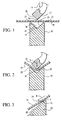
- Figure 1 is a broken-away, cross-sectional, largely schematic representation of a press brake punch and die of the invention, vertically aligned with a work piece between them, at the beginning of a bending operation,
- Figure 2 is a broken-away, cross-sectional, schematic representation similar to that of Figure 1, but showing the punch, die and work pieces at a point in the bending operation in which the work piece has been substantially bent;
- Figure 3 is a broken-away, cross-sectional, schematic view showing a portion of an edge surface of a die as it is contacted by the lower surface of a workpiece during a bending operation; and
- Figure 4 is a photographic representation comparing the surface characteristics of a die of the invention with a commercially available die.
- Nitriding and nitrocarburizing processes are known in the field and need not be described with great detail. Reference is made to US Patent 4,790,888 and 4,268,323, the latter patent referring to the use of a fused salt bath to enable nitrogen and carbon to diffuse into the surface of a steel piece suspended in the bath, to form a carbonitride case. Reference is made also to US Patents 5,234,721 (referring to methods of forming carbonitride coatings).
- Nitriding processes, both plasma (ion) nitriding and liquid nitriding, are described in detail in the ASM Handbook prepared under the direction of the ASM International Handbook Committee, Revised vol. 4: Heat Treating, pp. 410 - 424 (1994), the disclosures of which are incorporated by reference herein. Plasma or ion nitriding involves the use of glow discharge technology to provide nascent nitrogen to the surface of a heated steel part. Here, the part is subjected to a nitrogen plasma in a vacuum chamber. Nascent nitrogen diffuses into the surface of the part to form an outer "compound" zone containing y (Fe4N) and ε (Fe2,3N) intermetallics, and an inner "diffusion" zone which may be described as the original core microstructure with some solid solution and precipitation strengthening. Liquid nitriding involves immersing a steel part in a molten, nitrogen-containing fused salt bath containing cyanides or cyanates, e.g., NaCN or NaCNO.
- To utilize any of these processes, a steel or tempered steel press brake die is formed having smooth, spaced upper edge surfaces on either side of its groove, and either the edge surfaces of the die to be contacted by a workpiece, or these surfaces together with the upwardly divergent walls forming the V-shaped grove, or even larger portions or all of the tool, can be subjected to a selected nitriding or nitrocarburizing process. What is important here is that the spaced edge surfaces of the tool that encounter in a sliding fashion the work piece during a bending operation be subjected to the nitriding or nitrocarburizing process.
- With reference to Figures 1-3 a die of the invention is shown generally as 10, a complimentary shaped punch is shown as 12, and a work piece as 14. The die has an upwardly open groove, 16, having a
floor 18, and upwardly diverging walls, 20, as depicted, terminating in spaced dieedges 22. Thefloor 18 may be the intersection of the upwardlydivergent walls 20, or may be slightly rounded or slightly flattened, both for the purpose of avoiding stress concentration. As shown in Figure 3, theedge 22 has a generallyrounded edge surface 24 over which thework piece 14 slides during a bending operation. In a typical die of the invention, thegroove 16 formed by thewalls 20 may have an included angle ranging from 30 to 120 degrees, with each of thegroove walls 20 being oriented at from 15 to 60 degrees to the vertical. Dies having included angles of about 90 degrees are common. Theupper tool 12 is provided with a similar V-shape, as shown in Figures 1 and 2. - Arrow A in Figures 1 and 2 designate the direction of travel of the tool with respect to the die during a bending operation. If the included angle between the
walls 20 of the die groove is assumed to be 90 degrees with each wall oriented to the vertical at a 45 degree angle, then simple mathematics shows that as the work piece is depressed completely into the groove by a distance (measured vertically) of one unit of length, it slides against theedge surface 24 over a length of about 0.4 units of length. The majority of the sliding action of the work piece across theedge surface 24 occurs after the work piece has reached the halfway mark in its vertical descent toward thefloor 18 of the groove. The area of the edge surface contacted in a sliding, abrasive fashion by the work piece extends from about the upper curvedupper edge 22 of the die, whereas the flat surfaces of the die require somewhat less in the way of resistance to scratching, pitting or wear or the like. - Thus, in accordance with the present invention, that portion of the die which must be provided with a nitrided or nitrocarburized surface is the gently curved area of the die edge surface which is slidingly encountered by the work piece during a bending operation.
- Although, speaking broadly, only the edge surfaces of the die over which a work piece slides during a bending operation need be nitrided or nitrocarburized and hence rendered slippery and hard, as described herein, nitriding and nitrocarburizing processes common in the industry lend themselves to the hardening of larger surfaces, In this respect, it is appropriate to nitride or nitrocarburize the entire outer surface of the die, or at least the upper portion of the die that includes the V-shaped groove. Similarly, it may be appropriate to nitride or nitrocarburize the V-shaped punch that is received within the die, particularly the tip of the punch that initially encounters the work piece. Here, again, nitriding and nitrocarburizing processes may lend themselves most readily to harden either the entire punch, or at least that lower portion of the punch that includes the tip (26 in Figure 1) together with the upwardly
divergent walls 28 that form the V-shaped configuration of the punch tip. - Because of the resistance to scratching, pitting or wear due to the hardness of the
rounded edge portion 24 of the die, and its lubricity, the hardness of the die need not extend deeply into its surface. The nitriding and nitrocarburizing processes provide a surface having a hardness in the range of 52 - 70 Rockwell C (86 to 94 on a 15-N microhardness scale), and this hardness extends into the surface to a depth not greater than 1.52 mm (0.06 inches), and preferably not greater than about 0,75 mm (0.03 inches). This is in sharp contrast to temperature-induced hardening of steel, in which the hardness extends to a depth of 1/8" or more. Nitrided and nitrocarburized die surfaces of the invention are substantially slipperier than the surfaces of identical dies that have not been so treated. For example, nitrocarburized surfaces have coefficients of friction on the order of about two-thirds of the coefficients exhibited by untreated surfaces, or less. Whereas a temperature-hardened steel surface may exhibit a coefficient of friction of about 0.4, a nitrocarburized surface may exhibit a coefficient of about 0.08. - Over an extended testing period, the dies of the invention have shown superior resistance to damage when repeatedly bending a variety of workpiece materials. Various tests were run in which a nitrocarburized die of the invention was tested against a commercially available case hardened die. Here, the dies were subjected to repeated bending cycles using the same workpiece materials, and the dies were periodically inspected for wear.
Commercial Die Nitrocarburized Die Test 1 Wear appeared after 50 bends No wear after 2500 bends Test 2 Heavy wear after 300 bends No wear after 4500 bends Test 3 Wear appeared after 100 bends No wear after 1800 bends - Figure 4 shows the surface characteristics of two dies produced by Wilson Tool International, Inc., that were tested as above. The die on the left was heat hardened, and exhibits a substantial amount of scratching and wear, especially on the edges over which the workpiece slides. Dies that are damaged this badly are commonly replaced. The die on the right has a nitrocarburized surface that shows essentially no wear after undergoing approximately five times the number of bending cycles to which the die on the left was subjected.
- While a preferred embodiment of the present invention has been described, it should be understood that various changes, adaptations and modifications may be made therein without departing from the scope of the invention according to the appended claims.
Claims (5)
- Press brake tooling comprising a die (10) and mating punch (12) for bending sheet stock, said punch having an elongated, generally V-shaped punch tip (26) and said die being of steel and having an elongated, generally V-shaped groove (16) within which said punch tip is received during a bending operation, said groove having a floor (18) and sidewalls (20) extending from the floor and terminating in edges (22) spaced from each other across the width of the groove, said edges having edge surfaces configured to slidingly encounter the surface of a workpiece as it is bent between the tool and die, characterized in that at least said die edge surfaces have been nitrided or nitrocarburized to provide a slippery surface over which a work piece may slide, said surfaces having a hardness in the range of 52 - 70 Rockwell C with said hardness extending to a depth not exceeding about 1,52 mm (0.06 inches).
- The press brake tooling of claim 1 wherein said die edge surfaces have smoothly curved portions over which a work piece slides as it is bent, the smoothly curved portion being nitrided or nitrocarburized.
- The press brake tooling of claim 2 wherein said smoothly curved surfaces of the die edges together with the floor and side walls of the groove are nitrided or nitrocarburized.
- The press brake tooling of claim 3 wherein said punch tip that encounters a work piece is nitrided or nitrocarburized.
- The press brake tooling of any one of claims 1 - 4 in which said hardness of the nitrided or nitrocarburized surface extends to a depth of not more than 0,76 mm (0.03 inches).
Applications Claiming Priority (3)
| Application Number | Priority Date | Filing Date | Title |
|---|---|---|---|
| US09/672,698 US6327884B1 (en) | 2000-09-29 | 2000-09-29 | Press brake tooling with hardened surfaces |
| US672698 | 2000-09-29 | ||
| PCT/US2001/042418 WO2002026411A2 (en) | 2000-09-29 | 2001-09-28 | Press brake tooling with hardened surfaces |
Publications (2)
| Publication Number | Publication Date |
|---|---|
| EP1320426A2 EP1320426A2 (en) | 2003-06-25 |
| EP1320426B1 true EP1320426B1 (en) | 2005-09-21 |
Family
ID=24699636
Family Applications (1)
| Application Number | Title | Priority Date | Filing Date |
|---|---|---|---|
| EP01977870A Revoked EP1320426B1 (en) | 2000-09-29 | 2001-09-28 | Press brake tooling with hardened surfaces |
Country Status (8)
| Country | Link |
|---|---|
| US (1) | US6327884B1 (en) |
| EP (1) | EP1320426B1 (en) |
| AT (1) | ATE304903T1 (en) |
| AU (1) | AU2001296954A1 (en) |
| CA (1) | CA2427653C (en) |
| DE (1) | DE60113554T2 (en) |
| MX (1) | MXPA03002747A (en) |
| WO (1) | WO2002026411A2 (en) |
Families Citing this family (13)
| Publication number | Priority date | Publication date | Assignee | Title |
|---|---|---|---|---|
| US7596983B2 (en) | 2005-07-11 | 2009-10-06 | Wilson Tool International Inc. | Press brake clamp incorporating tool-seating mechanism |
| US20070056348A1 (en) * | 2005-09-09 | 2007-03-15 | David Leland | Brake punch inserts |
| DE602005025944D1 (en) * | 2005-11-11 | 2011-02-24 | Wila Bv | TOOLING TOOL WITH FIXING TOOLS FOR THE SECURITY MEMBER'S OPERATOR |
| US7913533B2 (en) * | 2006-02-16 | 2011-03-29 | Wilson Tool International Inc. | Machine tool cartridge with information storage device, smart cartridge systems, and methods of using smart cartridge systems |
| US7669453B2 (en) * | 2006-02-16 | 2010-03-02 | Wilson Tool International Inc. | Cartridge for machine tool |
| EP2004342B1 (en) | 2006-04-07 | 2014-10-15 | Wilson Tool International Inc. | Multi-tool technology |
| ATE501810T1 (en) * | 2006-06-01 | 2011-04-15 | Wila Bv | INTERCHANGEABLE TOOL/MANIPULATOR COMBINATION |
| DE602006019950D1 (en) * | 2006-06-01 | 2011-03-17 | Wila Bv | Tool with automatic locking |
| ATE497426T1 (en) * | 2006-06-07 | 2011-02-15 | Wila Bv | TOOL AND TOOL HOLDER, WITH A DATA EXCHANGE SYSTEM |
| US20080163728A1 (en) * | 2007-01-05 | 2008-07-10 | Snap-On Incorporated | Dual hardness connector |
| US7621201B2 (en) * | 2008-03-05 | 2009-11-24 | Gm Global Technology Operations, Inc. | Hot forming tools for aluminum and magnesium sheets |
| US20100119638A1 (en) * | 2008-11-07 | 2010-05-13 | Allis Carl R | Pelleting die and method for surface hardening pelleting dies |
| US9010218B2 (en) | 2010-05-14 | 2015-04-21 | Wilson Tool International Inc. | Bunter technology |
Family Cites Families (20)
| Publication number | Priority date | Publication date | Assignee | Title |
|---|---|---|---|---|
| US3240914A (en) | 1962-11-28 | 1966-03-15 | Gen Motors Corp | Method of making dies |
| JPS53137835A (en) | 1977-05-09 | 1978-12-01 | Toyoda Chuo Kenkyusho Kk | Method of forming carbide layer of va group element or chrome on surface of iron alloy material |
| US4268323A (en) | 1979-04-05 | 1981-05-19 | Kolene Corp. | Process for case hardening steel |
| US4446351A (en) | 1981-02-27 | 1984-05-01 | Mitsubishi Denki Kabushiki Kaisha | Process for preparing a press die |
| GB8431667D0 (en) * | 1984-12-14 | 1985-01-30 | Alcan Int Ltd | Extrusion dies |
| US4765847A (en) | 1985-06-17 | 1988-08-23 | Kabushiki Kaisha Toyota Chuo Kenkyusho | Method of treating the surface of iron alloy materials |
| US4738730A (en) | 1986-02-18 | 1988-04-19 | Lindberg Corporation | Steam sealing for nitrogen treated ferrous part |
| US4790888A (en) | 1986-10-22 | 1988-12-13 | Kolene Corporation | Stop-off composition |
| SE456650C (en) | 1987-03-19 | 1989-10-16 | Uddeholm Tooling Ab | POWDER METAL SURGICAL PREPARED STEEL STEEL |
| DE3841731C1 (en) * | 1988-12-10 | 1990-04-12 | Krupp Widia Gmbh, 4300 Essen, De | Process for coating a tool base, and tool produced by this process |
| US5234721A (en) | 1989-05-26 | 1993-08-10 | Rostoker, Inc. | Method for forming carbide coating on various metals and their alloys |
| US5095734A (en) * | 1990-12-14 | 1992-03-17 | William L. Bonnell Company, Inc. | Extrusion die and method for extruding aluminum |
| KR920019961A (en) | 1991-04-26 | 1992-11-20 | 기시다 도시오 | High Young's modulus material and surface coating tool member using it |
| US5244375A (en) | 1991-12-19 | 1993-09-14 | Formica Technology, Inc. | Plasma ion nitrided stainless steel press plates and applications for same |
| US5396788A (en) | 1992-09-04 | 1995-03-14 | Golden Technologies Company, Inc. | Can tooling components |
| JP2621010B2 (en) * | 1993-03-10 | 1997-06-18 | 東芝タンガロイ株式会社 | Mold for metal plastic working |
| US5542282A (en) * | 1994-03-09 | 1996-08-06 | Inner Act, Inc. | Markless press brake material protector |
| JPH0852515A (en) * | 1994-08-11 | 1996-02-27 | Amada Metrecs Co Ltd | Bending machine mold |
| US5921131A (en) * | 1996-06-28 | 1999-07-13 | Hutchinson Technology Incorporated | Method for frictionally guiding and forming ferrous metal |
| US6053722A (en) | 1998-07-28 | 2000-04-25 | Consolidated Process Machinery, Inc. | Nitrided H13-alloy cylindrical pelleting dies |
-
2000
- 2000-09-29 US US09/672,698 patent/US6327884B1/en not_active Expired - Lifetime
-
2001
- 2001-09-28 DE DE60113554T patent/DE60113554T2/en not_active Revoked
- 2001-09-28 WO PCT/US2001/042418 patent/WO2002026411A2/en not_active Ceased
- 2001-09-28 AU AU2001296954A patent/AU2001296954A1/en not_active Abandoned
- 2001-09-28 MX MXPA03002747A patent/MXPA03002747A/en active IP Right Grant
- 2001-09-28 EP EP01977870A patent/EP1320426B1/en not_active Revoked
- 2001-09-28 CA CA2427653A patent/CA2427653C/en not_active Expired - Lifetime
- 2001-09-28 AT AT01977870T patent/ATE304903T1/en not_active IP Right Cessation
Also Published As
| Publication number | Publication date |
|---|---|
| US6327884B1 (en) | 2001-12-11 |
| AU2001296954A1 (en) | 2002-04-08 |
| ATE304903T1 (en) | 2005-10-15 |
| WO2002026411A2 (en) | 2002-04-04 |
| CA2427653C (en) | 2010-02-09 |
| EP1320426A2 (en) | 2003-06-25 |
| WO2002026411A3 (en) | 2002-08-29 |
| MXPA03002747A (en) | 2004-05-04 |
| DE60113554T2 (en) | 2006-08-10 |
| DE60113554D1 (en) | 2005-10-27 |
| CA2427653A1 (en) | 2002-04-04 |
Similar Documents
| Publication | Publication Date | Title |
|---|---|---|
| US6327884B1 (en) | Press brake tooling with hardened surfaces | |
| US4581913A (en) | Method for improving the release and finish characteristics of metal stamping dies | |
| DE60314440D1 (en) | BONE SAW BLADE AND METHOD FOR PRODUCING A BONE SAW BLADE | |
| US20060201650A1 (en) | Mold for casting and method of surface treatment thereof | |
| US7152453B2 (en) | Press brake tool and tool holder | |
| US6858099B2 (en) | Steel material production method | |
| Karamiş | Friction and wear behaviour of plasma-nitrided layers on 3% Cr-Mo steel | |
| JPH0852515A (en) | Bending machine mold | |
| PT960666E (en) | MANUFACTURER AND PROCESS FOR A CUPBOARD | |
| US9010218B2 (en) | Bunter technology | |
| EP1570191B1 (en) | Method for producing a transverse element for a push belt for a continuously variable transmission | |
| JP2947099B2 (en) | Forming titanium sheet | |
| JPH01299723A (en) | Mechanical expander cone | |
| RU2121615C1 (en) | Method of manufacture of plate springs | |
| RU2058421C1 (en) | Method for nitriding parts of structural alloyed steels | |
| CN110205580A (en) | A kind of gas nitriding process of Automobile Plate hot-forming die | |
| SU610598A2 (en) | Method of machining the surface of articles | |
| RU2147746C1 (en) | Process determining hardness of diffusion layer with due account of configuration effect | |
| Child et al. | The effect of thermo chemical treatments on the mechanical properties of tool steel | |
| SU1196413A1 (en) | Method of machining die steel articles | |
| Korhonen et al. | New ways of improving the surface properties of metal forming tools | |
| Fukada et al. | Comparisons of fatigue strength among various nitrided die steels | |
| JPH08158037A (en) | Nitrided product with excellent rolling fatigue resistance and its manufacturing method | |
| Pecherskiy et al. | CALCULATIVE ESTIMATION OF THE DURABILITY OF THE HARDENED PARTS BASED ON THE GENERALIZED CRITERIA | |
| Golozar | Fatigue behaviour of case hardened low alloy Cr-Mo steel |
Legal Events
| Date | Code | Title | Description |
|---|---|---|---|
| PUAI | Public reference made under article 153(3) epc to a published international application that has entered the european phase |
Free format text: ORIGINAL CODE: 0009012 |
|
| 17P | Request for examination filed |
Effective date: 20030414 |
|
| AK | Designated contracting states |
Designated state(s): AT BE CH CY DE DK ES FI FR GB GR IE IT LI LU MC NL PT SE TR |
|
| AX | Request for extension of the european patent |
Extension state: AL LT LV MK RO SI |
|
| GRAP | Despatch of communication of intention to grant a patent |
Free format text: ORIGINAL CODE: EPIDOSNIGR1 |
|
| GRAS | Grant fee paid |
Free format text: ORIGINAL CODE: EPIDOSNIGR3 |
|
| GRAA | (expected) grant |
Free format text: ORIGINAL CODE: 0009210 |
|
| AK | Designated contracting states |
Kind code of ref document: B1 Designated state(s): AT BE CH CY DE DK ES FI FR GB GR IE IT LI LU MC NL PT SE TR |
|
| PG25 | Lapsed in a contracting state [announced via postgrant information from national office to epo] |
Ref country code: BE Free format text: LAPSE BECAUSE OF FAILURE TO SUBMIT A TRANSLATION OF THE DESCRIPTION OR TO PAY THE FEE WITHIN THE PRESCRIBED TIME-LIMIT Effective date: 20050921 Ref country code: AT Free format text: LAPSE BECAUSE OF FAILURE TO SUBMIT A TRANSLATION OF THE DESCRIPTION OR TO PAY THE FEE WITHIN THE PRESCRIBED TIME-LIMIT Effective date: 20050921 Ref country code: LI Free format text: LAPSE BECAUSE OF FAILURE TO SUBMIT A TRANSLATION OF THE DESCRIPTION OR TO PAY THE FEE WITHIN THE PRESCRIBED TIME-LIMIT Effective date: 20050921 Ref country code: CH Free format text: LAPSE BECAUSE OF FAILURE TO SUBMIT A TRANSLATION OF THE DESCRIPTION OR TO PAY THE FEE WITHIN THE PRESCRIBED TIME-LIMIT Effective date: 20050921 |
|
| REG | Reference to a national code |
Ref country code: GB Ref legal event code: FG4D |
|
| PG25 | Lapsed in a contracting state [announced via postgrant information from national office to epo] |
Ref country code: IE Free format text: LAPSE BECAUSE OF NON-PAYMENT OF DUE FEES Effective date: 20050928 Ref country code: CY Free format text: LAPSE BECAUSE OF FAILURE TO SUBMIT A TRANSLATION OF THE DESCRIPTION OR TO PAY THE FEE WITHIN THE PRESCRIBED TIME-LIMIT Effective date: 20050928 |
|
| PG25 | Lapsed in a contracting state [announced via postgrant information from national office to epo] |
Ref country code: MC Free format text: LAPSE BECAUSE OF NON-PAYMENT OF DUE FEES Effective date: 20050930 |
|
| REG | Reference to a national code |
Ref country code: CH Ref legal event code: EP |
|
| REG | Reference to a national code |
Ref country code: IE Ref legal event code: FG4D |
|
| REF | Corresponds to: |
Ref document number: 60113554 Country of ref document: DE Date of ref document: 20051027 Kind code of ref document: P |
|
| PG25 | Lapsed in a contracting state [announced via postgrant information from national office to epo] |
Ref country code: LU Free format text: LAPSE BECAUSE OF NON-PAYMENT OF DUE FEES Effective date: 20051121 |
|
| PG25 | Lapsed in a contracting state [announced via postgrant information from national office to epo] |
Ref country code: GR Free format text: LAPSE BECAUSE OF FAILURE TO SUBMIT A TRANSLATION OF THE DESCRIPTION OR TO PAY THE FEE WITHIN THE PRESCRIBED TIME-LIMIT Effective date: 20051221 Ref country code: SE Free format text: LAPSE BECAUSE OF FAILURE TO SUBMIT A TRANSLATION OF THE DESCRIPTION OR TO PAY THE FEE WITHIN THE PRESCRIBED TIME-LIMIT Effective date: 20051221 Ref country code: DK Free format text: LAPSE BECAUSE OF FAILURE TO SUBMIT A TRANSLATION OF THE DESCRIPTION OR TO PAY THE FEE WITHIN THE PRESCRIBED TIME-LIMIT Effective date: 20051221 |
|
| PG25 | Lapsed in a contracting state [announced via postgrant information from national office to epo] |
Ref country code: ES Free format text: LAPSE BECAUSE OF FAILURE TO SUBMIT A TRANSLATION OF THE DESCRIPTION OR TO PAY THE FEE WITHIN THE PRESCRIBED TIME-LIMIT Effective date: 20060101 |
|
| PG25 | Lapsed in a contracting state [announced via postgrant information from national office to epo] |
Ref country code: PT Free format text: LAPSE BECAUSE OF FAILURE TO SUBMIT A TRANSLATION OF THE DESCRIPTION OR TO PAY THE FEE WITHIN THE PRESCRIBED TIME-LIMIT Effective date: 20060221 |
|
| REG | Reference to a national code |
Ref country code: CH Ref legal event code: PL |
|
| ET | Fr: translation filed | ||
| PLBI | Opposition filed |
Free format text: ORIGINAL CODE: 0009260 |
|
| REG | Reference to a national code |
Ref country code: IE Ref legal event code: MM4A |
|
| PLAX | Notice of opposition and request to file observation + time limit sent |
Free format text: ORIGINAL CODE: EPIDOSNOBS2 |
|
| 26 | Opposition filed |
Opponent name: TRUMPF WERKZEUGMASCHINEN GMBH + CO. KG Effective date: 20060621 |
|
| NLR1 | Nl: opposition has been filed with the epo |
Opponent name: TRUMPF WERKZEUGMASCHINEN GMBH + CO. KG |
|
| PLAF | Information modified related to communication of a notice of opposition and request to file observations + time limit |
Free format text: ORIGINAL CODE: EPIDOSCOBS2 |
|
| PLAF | Information modified related to communication of a notice of opposition and request to file observations + time limit |
Free format text: ORIGINAL CODE: EPIDOSCOBS2 |
|
| PLBB | Reply of patent proprietor to notice(s) of opposition received |
Free format text: ORIGINAL CODE: EPIDOSNOBS3 |
|
| PGFP | Annual fee paid to national office [announced via postgrant information from national office to epo] |
Ref country code: TR Payment date: 20070905 Year of fee payment: 7 |
|
| PLAY | Examination report in opposition despatched + time limit |
Free format text: ORIGINAL CODE: EPIDOSNORE2 |
|
| PLAH | Information related to despatch of examination report in opposition + time limit modified |
Free format text: ORIGINAL CODE: EPIDOSCORE2 |
|
| PLAH | Information related to despatch of examination report in opposition + time limit modified |
Free format text: ORIGINAL CODE: EPIDOSCORE2 |
|
| PLAH | Information related to despatch of examination report in opposition + time limit modified |
Free format text: ORIGINAL CODE: EPIDOSCORE2 |
|
| PLBC | Reply to examination report in opposition received |
Free format text: ORIGINAL CODE: EPIDOSNORE3 |
|
| PLBP | Opposition withdrawn |
Free format text: ORIGINAL CODE: 0009264 |
|
| PGFP | Annual fee paid to national office [announced via postgrant information from national office to epo] |
Ref country code: FI Payment date: 20080915 Year of fee payment: 8 Ref country code: FR Payment date: 20080915 Year of fee payment: 8 Ref country code: NL Payment date: 20080903 Year of fee payment: 8 |
|
| PGFP | Annual fee paid to national office [announced via postgrant information from national office to epo] |
Ref country code: DE Payment date: 20081002 Year of fee payment: 8 |
|
| RDAF | Communication despatched that patent is revoked |
Free format text: ORIGINAL CODE: EPIDOSNREV1 |
|
| PGFP | Annual fee paid to national office [announced via postgrant information from national office to epo] |
Ref country code: IT Payment date: 20080927 Year of fee payment: 8 |
|
| RDAG | Patent revoked |
Free format text: ORIGINAL CODE: 0009271 |
|
| STAA | Information on the status of an ep patent application or granted ep patent |
Free format text: STATUS: PATENT REVOKED |
|
| PGFP | Annual fee paid to national office [announced via postgrant information from national office to epo] |
Ref country code: GB Payment date: 20081001 Year of fee payment: 8 |
|
| 27W | Patent revoked |
Effective date: 20090303 |
|
| GBPR | Gb: patent revoked under art. 102 of the ep convention designating the uk as contracting state |
Effective date: 20090303 |
|
| NLR2 | Nl: decision of opposition |
Effective date: 20090303 |