EP1319883A1 - Inflation nozzle assembly - Google Patents
Inflation nozzle assembly Download PDFInfo
- Publication number
- EP1319883A1 EP1319883A1 EP02258465A EP02258465A EP1319883A1 EP 1319883 A1 EP1319883 A1 EP 1319883A1 EP 02258465 A EP02258465 A EP 02258465A EP 02258465 A EP02258465 A EP 02258465A EP 1319883 A1 EP1319883 A1 EP 1319883A1
- Authority
- EP
- European Patent Office
- Prior art keywords
- inflation
- inflation nozzle
- nozzle
- housing
- air
- Prior art date
- Legal status (The legal status is an assumption and is not a legal conclusion. Google has not performed a legal analysis and makes no representation as to the accuracy of the status listed.)
- Granted
Links
- 230000013011 mating Effects 0.000 claims abstract description 3
- 239000012530 fluid Substances 0.000 description 4
- 238000004519 manufacturing process Methods 0.000 description 2
- 230000002093 peripheral effect Effects 0.000 description 2
- 230000005540 biological transmission Effects 0.000 description 1
- 238000010276 construction Methods 0.000 description 1
- 230000000694 effects Effects 0.000 description 1
- 230000006870 function Effects 0.000 description 1
- 238000003780 insertion Methods 0.000 description 1
- 230000037431 insertion Effects 0.000 description 1
- 230000000717 retained effect Effects 0.000 description 1
- 238000007789 sealing Methods 0.000 description 1
- 230000015541 sensory perception of touch Effects 0.000 description 1
- 230000000007 visual effect Effects 0.000 description 1
Images


Classifications
-
- F—MECHANICAL ENGINEERING; LIGHTING; HEATING; WEAPONS; BLASTING
- F16—ENGINEERING ELEMENTS AND UNITS; GENERAL MEASURES FOR PRODUCING AND MAINTAINING EFFECTIVE FUNCTIONING OF MACHINES OR INSTALLATIONS; THERMAL INSULATION IN GENERAL
- F16L—PIPES; JOINTS OR FITTINGS FOR PIPES; SUPPORTS FOR PIPES, CABLES OR PROTECTIVE TUBING; MEANS FOR THERMAL INSULATION IN GENERAL
- F16L37/00—Couplings of the quick-acting type
- F16L37/08—Couplings of the quick-acting type in which the connection between abutting or axially overlapping ends is maintained by locking members
- F16L37/12—Couplings of the quick-acting type in which the connection between abutting or axially overlapping ends is maintained by locking members using hooks, pawls, or other movable or insertable locking members
-
- B—PERFORMING OPERATIONS; TRANSPORTING
- B60—VEHICLES IN GENERAL
- B60P—VEHICLES ADAPTED FOR LOAD TRANSPORTATION OR TO TRANSPORT, TO CARRY, OR TO COMPRISE SPECIAL LOADS OR OBJECTS
- B60P7/00—Securing or covering of load on vehicles
- B60P7/06—Securing of load
- B60P7/065—Securing of load by pressurizing or creating a vacuum in a bag, cover or the like
-
- F—MECHANICAL ENGINEERING; LIGHTING; HEATING; WEAPONS; BLASTING
- F16—ENGINEERING ELEMENTS AND UNITS; GENERAL MEASURES FOR PRODUCING AND MAINTAINING EFFECTIVE FUNCTIONING OF MACHINES OR INSTALLATIONS; THERMAL INSULATION IN GENERAL
- F16L—PIPES; JOINTS OR FITTINGS FOR PIPES; SUPPORTS FOR PIPES, CABLES OR PROTECTIVE TUBING; MEANS FOR THERMAL INSULATION IN GENERAL
- F16L37/00—Couplings of the quick-acting type
- F16L37/26—Couplings of the quick-acting type in which the connection is made by transversely moving the parts together, with or without their subsequent rotation
Definitions
- the present invention relates generally to dunnage air bags, and more particularly to a new and improved inflation nozzle fixture or assembly for inflating the inflatable bladder disposed interiorly of the dunnage air bag in connection with the use of the dunnage air bag for securing or bracing cargo within the holds of, for example, railroad cars, airplanes, ships, truck trailers, and the like.
- Cargo or dunnage air bags are used in the cargo shipment or transportation industry as a means for readily and easily securing or bracing cargo within the holds of, for example, railroad cars, ships, airplanes, truck trailers, and the like.
- Such dunnage or cargo air bags conventionally comprise an inflatable bladder which is enclosed within an outer bag or envelope fabricated from a plurality of paper plies.
- the air bags are conventionally of such construction and size as to readily enable the same to be inserted into voids or spaces defined between spaced loads, or between a particular cargo load and a side or end wall of the cargo container or hold, where upon inflation of the air bag, the air bag will expand thereby fixedly engaging the adjacent cargo loads or the cargo load and container wall so as to secure the cargo loads against undesirable movement during transit.
- the inflation valve comprises a tubular valve body having a flange portion integrally fixed thereto.
- the flange portion is welded or heat-sealed to an interior wall portion Of the inflatable bladder so as to form an airtight seal therewith, whereas the tubular valve body projects outwardly from the air bag so as to be externally accessible for fluidic communication with a suitable air inflation fixture or assembly by means of which the compressed or pressurized air can be conducted into the interior portion of the inflatable bladder.
- the inflation valve also comprises a valve stem which is mounted within the tubular valve body and is movable between CLOSED and OPEN states.
- the valve stem is normally spring-biased toward the CLOSED state but is able to be moved to the OPEN state against the spring-biasing force by means of the air inflation fixture or assembly.
- the inflation nozzle or fixture comprises a relatively large number of operative components and is relatively difficult to manipulate. More particularly, the inflation nozzle or fixture 14 is seen to comprise a tubular body portion 24 which is adapted to be threadedly connected to a hose 16 which, in turn, is adapted to be fluidically connected to a source of compressed air, not shown, wherein the tubular body portion 24 comprises an air inlet portion 34 and an air outlet portion 36 which is formed by means of a tubular nozzle tip 42.
- a handle 26 is pivotally mounted upon the tubular body portion 24 by means of a pivot pin 28, and a coil spring 30 is interposed between the handle 26 and the tubular body portion 24 so as to normally bias the handle 26 toward a position at which the forward end 32 of the handle 26 is moved toward the air outlet 36 of the tubular body portion 24.
- the forward end 32 of the handle 26 also comprises a recessed or cut-out region or portion 44 which is bounded by side walls or guides 46, and a closure plate 48 is adapted to slide over the recessed portion 44 so as to normally cover the air outlet 36.
- the closure plate 48 is movably mounted within the handle 26 by means of a pin and slot mechanism 50,52, and a coil spring 54 normally biases the closure plate 48 toward the forward end 32 of the handle 26.
- the air bag inflation valve 12 comprises a tubular valve body 56 which extends through the wall 58 of the air bag 10, and an annular flange 60 which is sealed to the interior wall portion of the plastic bladder 62.
- An annular valve seat 64 is disposed interiorly of the bladder 62, and the tubular valve body 56 projects outwardly from the air bag 10 such that a first annular edge portion 66 of the valve body 56 engages an outer surface portion of the air bag 10 so as to cooperate with the flange portion 60 in securing the inflation valve 12 upon the air bag 10.
- the inflation valve 12 further comprises an axially movable valve stem 70 which includes an annular closure plate 72 comprising an annular ridge portion 74 for cooperating with the annular valve seat 64.
- a coil spring 76 normally biases the valve stem 70 to its CLOSED position at which the annular ridge portion 74 is engaged with the valve seat 64, while alternatively, the valve stem 70 is movable to its OPENED position, against the biasing force of the coil spring 76, when the nozzle tip 42 engages the end 78 of the valve stem 70 which is disposed opposite the closure plate 72.
- an operator grasps the inflation fixture or mechanism 14 and upon squeezing the handle 26, the handle 26 will pivot around pivot pin 28 such that the forward end 32 of the handle 26 and the closure plate 48 will move away from the nozzle tip 42.
- the inflation nozzle 14 is then slid or moved upwardly and transversely with respect to the axis of the inflation valve 12 such that the free end 80 of the valve body 56 moves past the nozzle tip 42, effectively enters the recessed portion or cut-out region 44 of the handle 26, and engages the closure plate 48 of the handle 26 so as to move the same downwardly against the biasing force of the spring 54 while the side walls 46 of the handle 26 are secured behind a second annular edge portion 68 of the valve body 56.
- spring 30 Upon release of the hand pressure of the operator which initially achieved squeezing of the handle 26, spring 30 effectively causes the main body 24 to pivot away from the handle 26 whereby the nozzle tip 42 engages the end 78 of the valve stem 70 so as to move the valve stern 70 to its OPENED position against the biasing force of spring 76. Inflation of the air bag 10 can then be achieved.
- the aforenoted and briefly described inflation fixture or assembly 14 is operatively viable and reliable, and has accordingly been commercially successful, it is relatively costly to manufacture due to the relatively large number of component parts.
- the operative mating of the inflation fixture or assembly 14 with the air bag inflation valve 12 is sometimes relatively difficult to achieve because there is no positional limit or stop effectively positioning the tree end portion 80 of the valve body 56 at the proper position with respect to the nozzle tip 42 so as to permit the nozzle tip 42 to freely enter the free end portion 80 of the valve body 56 and thereby engage the end portion 78 of the valve stem 70. If the nozzle tip 42 is not properly coaxially aligned with the free end portion 80 of the valve body 56.
- a peripheral portion of the nozzle tip 42 will engage a peripheral portion of the free end portion SO of the valve body 56, the nozzle tip 42 will not be properly positioned within the free end portion 80 of the valve body 56 so as to properly engage the end portion 78 of the valve stem 70, and just as importantly, the inflation fixture or assembly 14 will not be securely seated or affixed upon the valve body 56 whereby proper inflation of the airbag will not be able to be readily achieved.
- an airbag inflation nozzle fixture or assembly comprises an inflation nozzle housing within which an airbag inflation nozzle member is pivotally mounted.
- the inflation nozzle housing comprises a pair of oppositely disposed side walls and an end wall integrally interconnecting the pair of side walls, and a substantially U-shaped track and rail structure is integrally provided upon the lowermost portions of the side walls and end wall so as to permit an annular edge or flanged portion of an airbag inflation valve body to effectively move therealong when the inflation nozzle housing is being mounted upon the inflation valve body.
- the inflation nozzle member comprises an inflation nozzle tip, and the end wall of the inflation nozzle housing serves as a stop member for limiting the relative movement of the inflation valve body into the inflation nozzle housing so as to always ensure proper coaxial alignment of the inflation nozzle tip and the inflation valve body, an inflation valve stem being axially movable within the inflation valve body between OPENED and CLOSED positions.
- the inflation nozzle housing is further provided with a camming lock button which is movable in a transverse direction, with respect to the axes of the inflation nozzle tip and the inflation valve body, between UNLOCKED and LOCKED positions.
- the camming lock button is moved from its UNLOCKED position to its LOCKED position at which position the camming lock button engages the inflation nozzle member so as to pivot the same slightly and forcefully insert the inflation nozzle tip into the inflation valve body and thereby engage the inflation valve stem whereby the inflation valve stem is moved to its OPENED position.
- the inflation nozzle assembly comprising the inflation nozzle housing and the inflation nozzle member, is now disposed in a LOCKED position upon the inflation valve body whereby inflation of the airbag can be readily, easily, and properly achieved.
- the airbag inflation nozzle assembly 110 is relatively simple in structure in that the same substantially comprises only three operative components comprising an airbag inflation assembly housing 112, an airbag inflation assembly nozzle member 114, and a camming locking button 116.
- the nozzle member 114 is adapted to be mounted upon the housing 112 by means of a pivot pin 118 such that, as will become more apparent hereinafter, when the nozzle member 114 is mounted upon the housing 112, the nozzle member 114 can undergo or experience limited pivotal movement relative to the housing 112 between a first DISENGAGED and UNLOCKED position with respect to the tubular inflation valve body member 120 of an airbag inflation valve assembly 122, as disclosed within FIGURE 11, and a second ENGAGED and LOCKED position with respect to the tubular inflation valve body member 120 of the airbag inflation valve assembly 122, as disclosed within FIGURES 12 and 13, so as to move the valve stem portion, not shown, of the inflation valve assembly 122 to an OPENED position and thereby enable inflation of the cargo airbag to which the inflation valve assembly 122 is operatively connected.
- the airbag inflation nozzle member 114 comprises a first enlarged tubular end portion 124 which is internally tapped or threaded as at 126 so as to facilitate the threaded attachment of an air hose, not shown 1 thereto by means of which a supply of compressed air can be transmitted to the airbag inflation nozzle member 114 for ultimate transmission to the airbag inflation valve assembly 122.
- Tubular end portion 124 of nozzle member 114 is fluidically connected to a fluid passageway 128 which is coaxially oriented with respect to the tubular end portion 124, and it is seen that the fluid passageway 128 extends axially through an elongated body portion 130 of the nozzle member 114.
- the axial fluid passageway 128 is, in turn, fluidically connected to a transversely or radially oriented fluid passageway 132 which is defined within a nozzle tip portion 134 of the nozzle member 114.
- the nozzle tip portion 134 comprises an annularly recessed portion 136 defined between an annular flanged distal end portion 138 and a shoulder portion 140, and an 0-ring seal member 142, as seen in FIGURES 11-13, is adapted to be captured between the flanged distal end portion 138 and the shoulder portion 140 so as to be seated within the annularly recessed portion 136. It is to be noted, as may best be appreciated from FIGURE 12, that the diametrical extent of the flanged distal end portion 138 of the nozzle tip portion 134 is less than the diametrical extent of the tubular distal end portion 144 of the tubular inflation valve body member 120 of the airbag inflation valve assembly 122.
- the nozzle member 114 when the nozzle member 114 is pivoted about pivot pin 118 so as to be disposed at its ENGAGED position with respect to the tubular inflation valve body member 120 of the airbag inflation valve assembly 122, the distal end portion 138 of the nozzle tip portion 134 will be disposed internally within the distal end portion 144 of the valve body member 120 so as to actuate the valve stem member, not shown, of the valve assembly 122, while the 0-ring member 142 will be seated upon the external periphery of the distal end portion 144 of the valve body member 120.
- the airbag inflation assembly housing 112 comprises an upper wall 146, a pair of oppositely disposed side walls 148,150 integral with the upper wall 146, and a front end wall 152 integral with the upper wall 146 and the pair of oppositely disposed side walls 148,150. It is thus apparent that the bottom section of the assembly housing 112, disposed opposite the upper wall 146, as well as the rear end portion of the assembly housing 112, disposed opposite the front end wall 152, are open so as to permit the insertion therewithin of the airbag inflation assembly nozzle member 114.
- an arcuately recessed portion 154 is defined within the rear end portion of the upper wall 146 and the upper end portions of each one of the oppositely disposed side walls 148,150, as best seen in, or appreciated from, FIGURE 13, so as to effectively provide a seat for the enlarged tubular end portion 124 of the nozzle member 114, as best seen in FIGURES 11 and 12, when the nozzle member 114 is mounted within the assembly housing 112 and, in particular, when the nozzle member 114 is moved to, and disposed at, its LOCKED and ENGAGED position with respect to the valve body member 120 of the airbag inflation valve assembly 122.
- the nozzle member 114 is pivotally mounted within the housing 112 so as to be movable between its atorenoted first DISENGAGED and UNLOCKED position, arid its second ENGAGED and LOCKED position.
- a substantially rectangularly configured recessed region 162 is defined within the front end wall 152 of the airbag inflation assembly housing 112, and accordingly, a shoulder portion 164 is provided within. the front end wall 152.
- the forward end section 166 of the elongated body portion 130 of the nozzle member 114 protrudes or extends beyond that section of the nozzle tip portion 134 within which the shoulder portion 140 is provided so as to define a lug 168 which is adapted to engage and be seated upon shoulder portion 164 of recessed region 162 of the housing 112 when the nozzle member 114 is moved downwardly from its DISENGAGED and UNLOCKED position as shown in FIGURE 11 to its ENGAGED and LOCKED position as shown in FIGURE 12.
- the nozzle member 114 is fixedly retained at its ENGAGED and LOCKED position with respect to the valve body member 120 of the inflation valve assembly 122, and in particular with respect to the distal end portion 144 of the valve body member 120, so as to ensure proper actuation of the valve stem member, not shown, of the valve assembly 122 and the subsequent inflation of the airbag.
- the airbag inflation nozzle assembly 110 of the present invention is provided with the unique and novel structure comprising the aforenoted camming locking button 116 which is shown in detail in FIGURE 10.
- the side walls 148,150 of the housing 112 are respectively provided with through-bores 170,172 through which opposite ends of the camming locking button 116 are adapted to be movably disposed.
- the through-bores 170,172 have substantially circular configurations, except that the uppermost portion of each through-bore 170,172 has a flattened or planar section, as shown, for example, at 174 in FIGURE 8 in connection with through-bore 172.
- the camming locking button 116 has a similar, substantially circular cross-sectional configuration, except that the uppermost portion of the camming locking button 116 is likewise flattened or planar as indicated at 176 in FIGURE 10.
- the flattened or planar sections of through-bores 170,172 accordingly match and accommodate the similarly flattened or planar uppermost section 176 of the camming locking button 116, and in this manner, rotational movement of the camming locking button 116 is effectively prevented such that movement of the camming locking button 116 within the through-bores 170,172, and between the UNLOCKED and LOCKED positions of the camming locking button 116, is solely reciprocal and. linear.
- the upper wall 146 of the housing 112 is also provided with a planar, recessed groove 178 which in effect is a continuation of the flattened or planar sections of the through-bores 170,172 defined within the side walls 148,150 of the housing 112, and in this manner, the camming locking button 116 is linearly guided during its reciprocal movements between the UNLOCKED and LOCKED positions.
- the upper forward surface section of the elongated body portion 130 of the nozzle member 114 is seen to comprise, as best seen in FIGURE 6, an uppermost, horizontally disposed planar surface section 180 and a pair of downwardly inclined surface sections 182,184 disposed upon opposite sides of the planar surface section 180.
- the undersurface portion of the camming locking button 116 is provided with a vertically stepped recessed region comprising a first upper, horizontally disposed planar surface section 186 and a pair of downwardly inclined surface sections 188,190 disposed upon opposite sides of the first upper planar surface section 186.
- the undersurface recessed portion of the camming locking button 116 is also provided with a second lower, horizontally disposed planar surface 192, and a third downwardly inclined surface section 194. It can therefore be readily appreciated.
- the camming locking button 116 when the camming locking button 116 is linearly moved toward the right as seen in FIGURE 10 and in accordance with the arrow designated UNLOCKED such that the camming locking button 116 is effectively disposed at its UNLOCKED position with respect to the nozzle member 114, the planar and inclined surface sections 180, 182. and 184 of the nozzle member 114 will be accommodated within the recessed undersurface region of the camming locking button 116 as defined by the corresponding planar and inclined surface sections 186,188, and 190 whereby the nozzle member 114 is free to achieve its pivoted UNLOCKED and DISENGAGED state with respect to the valve body member 120 of the inflation valve assembly 122 as can be seen in FIGURE 11.
- the camming locking button 116 When, however, the camming locking button 116 is linearly moved toward the left as seen in FIGURE 10 and in accordance with the arrow designated LOCKED such that the camming locking button 116 is effectively disposed at its LOCKED position with respect to the nozzle member 114, the inclined surface section 190 will forcefully engage the inclined surface section 184 of the nozzle member 114 and cause the same to effectively move downwardly along the inclined surface section 190 of the camming locking button 116 until the second lower, horizontally disposed planar surface 192 can be disposed atop the upper planar surface section 180 of the nozzle member 114 and the third inclined surface section 194 of the camming locking button 116 is disposed in engaged.
- the nozzle member 114 has now been pivotally moved downwardly from its UNLOCKED and DISENGAGED state with respect to the valve body member 120 of the inflation valve assembly 122 as shown in FIGURE 11 to its LOCKED and ENGAGED state with respect to the valve body member 120 of the inflation valve assembly 122 as shown in FIGURE 12 whereby inflation of the inflatable airbag can be achieved.
- a last significant feature of the airbag inflation assembly 110 as constructed in accordance with the teachings and principles of the present invention resides in the provision of structure therewithin for automatically achieving the proper disposition or positioning of the airbag inflation housing 112 and the airbag inflation nozzle member 114 with respect or relative to the valve body member 120 of the inflation valve assembly 122 when the airbag inflation nozzle assembly 110 is being mounted upon the valve body member 120 of the inflation valve assembly 122 so as to always ensure coaxial alignment of the airbag inflation nozzle member 114 with respect to the valve body member 120 of the inflation valve assembly 122 and the consequent proper inflation of the airbag.
- each one of the side walls 148,150 of the housing 112 is provided, at its lowermost end portion, with a transversely inwardly extending flanged portion 195,198, and in a similar manner, the end wall 152 is provided, at its lowermost end portion, with an axially inwardly extending flanged portion 200 wherein the flanged portions 196, 198,200 are continuous and integral with each other so as to effectively define a substantially U-shaped ledge having side ledge portions 202,204, and an end ledge portion 206.
- the side walls 14,150 of the housing 112 effectively define an open-ended slot 207 within which the valve body member 120 can be inserted and the ledge portions 202,204 will effectively serve as rail members upon which the lower annular edge portion 208 of the distal end portion 144 of the tubular inflation valve body member 120 will ride.
- an annularly recessed region 210 is also defined between the distal end portion 144 of the valve body member 120 and a second flanged portion 212 of valve body member 120 which is adapted to engage the external surface of the inflatable airbag, not shown, when valve body member 120 is mounted upon the airbag.
- a relatively simple airbag inflation nozzle assembly has been developed and constructed wherein the inflation nozzle assembly is easy to manipulate and use, wherein the inflation nozzle assembly is easy to mount upon the inflation valve assembly of the airbag to be inflated, wherein the inflation nozzle assembly comprises structure for always ensuring that the nozzle tip portion will be properly coaxially aligned with respect to the inflation valve assembly upon the airbag so as to properly actuate the valve stem component thereof and thereby achieve inflation of the airbag, and wherein the inflation nozzle assembly can be easily disposed within UNLOCKED and LOCKED states with respect to the inflation valve body member of the inflation valve assembly.
Landscapes
- Engineering & Computer Science (AREA)
- General Engineering & Computer Science (AREA)
- Mechanical Engineering (AREA)
- Transportation (AREA)
- Vehicle Cleaning, Maintenance, Repair, Refitting, And Outriggers (AREA)
- Compressors, Vaccum Pumps And Other Relevant Systems (AREA)
- Buffer Packaging (AREA)
- Air Bags (AREA)
- Quick-Acting Or Multi-Walled Pipe Joints (AREA)
- Check Valves (AREA)
- Mechanically-Actuated Valves (AREA)
Abstract
Description
- The present invention relates generally to dunnage air bags, and more particularly to a new and improved inflation nozzle fixture or assembly for inflating the inflatable bladder disposed interiorly of the dunnage air bag in connection with the use of the dunnage air bag for securing or bracing cargo within the holds of, for example, railroad cars, airplanes, ships, truck trailers, and the like.
- Cargo or dunnage air bags are used in the cargo shipment or transportation industry as a means for readily and easily securing or bracing cargo within the holds of, for example, railroad cars, ships, airplanes, truck trailers, and the like. Such dunnage or cargo air bags conventionally comprise an inflatable bladder which is enclosed within an outer bag or envelope fabricated from a plurality of paper plies. The air bags are conventionally of such construction and size as to readily enable the same to be inserted into voids or spaces defined between spaced loads, or between a particular cargo load and a side or end wall of the cargo container or hold, where upon inflation of the air bag, the air bag will expand thereby fixedly engaging the adjacent cargo loads or the cargo load and container wall so as to secure the cargo loads against undesirable movement during transit. Obviously, in order to achieve the inflation of the cargo or dunnage air bags to a predetermined pressurized level, such airbags are also conventionally provided with an inflation valve which permits compressed or pressurized air to be conducted into the interior portion of the inflatable bladder. Typically, the inflation valve comprises a tubular valve body having a flange portion integrally fixed thereto. The flange portion is welded or heat-sealed to an interior wall portion Of the inflatable bladder so as to form an airtight seal therewith, whereas the tubular valve body projects outwardly from the air bag so as to be externally accessible for fluidic communication with a suitable air inflation fixture or assembly by means of which the compressed or pressurized air can be conducted into the interior portion of the inflatable bladder. The inflation valve also comprises a valve stem which is mounted within the tubular valve body and is movable between CLOSED and OPEN states. The valve stem is normally spring-biased toward the CLOSED state but is able to be moved to the OPEN state against the spring-biasing force by means of the air inflation fixture or assembly.
- A conventional or PRIOR ART inflation nozzle or fixture, for enabling the inflation of an inflatable bladder of a cargo air bag, is disclosed US-A-5,042,541, however, as can be readily appreciated from FIGURE 1, which corresponds substantially to FIGURE 3 of the aforenoted patent, the inflation nozzle or fixture comprises a relatively large number of operative components and is relatively difficult to manipulate. More particularly, the inflation nozzle or
fixture 14 is seen to comprise atubular body portion 24 which is adapted to be threadedly connected to ahose 16 which, in turn, is adapted to be fluidically connected to a source of compressed air, not shown, wherein thetubular body portion 24 comprises anair inlet portion 34 and anair outlet portion 36 which is formed by means of atubular nozzle tip 42. Ahandle 26 is pivotally mounted upon thetubular body portion 24 by means of apivot pin 28, and acoil spring 30 is interposed between thehandle 26 and thetubular body portion 24 so as to normally bias thehandle 26 toward a position at which theforward end 32 of thehandle 26 is moved toward theair outlet 36 of thetubular body portion 24. Theforward end 32 of thehandle 26 also comprises a recessed or cut-out region orportion 44 which is bounded by side walls orguides 46, and aclosure plate 48 is adapted to slide over therecessed portion 44 so as to normally cover theair outlet 36. Theclosure plate 48 is movably mounted within thehandle 26 by means of a pin andslot mechanism coil spring 54 normally biases theclosure plate 48 toward theforward end 32 of thehandle 26. - The air
bag inflation valve 12 comprises atubular valve body 56 which extends through thewall 58 of theair bag 10, and anannular flange 60 which is sealed to the interior wall portion of theplastic bladder 62. Anannular valve seat 64 is disposed interiorly of thebladder 62, and thetubular valve body 56 projects outwardly from theair bag 10 such that a firstannular edge portion 66 of thevalve body 56 engages an outer surface portion of theair bag 10 so as to cooperate with theflange portion 60 in securing theinflation valve 12 upon theair bag 10. Theinflation valve 12 further comprises an axiallymovable valve stem 70 which includes anannular closure plate 72 comprising anannular ridge portion 74 for cooperating with theannular valve seat 64. Acoil spring 76 normally biases thevalve stem 70 to its CLOSED position at which theannular ridge portion 74 is engaged with thevalve seat 64, while alternatively, thevalve stem 70 is movable to its OPENED position, against the biasing force of thecoil spring 76, when thenozzle tip 42 engages theend 78 of thevalve stem 70 which is disposed opposite theclosure plate 72. - In use, an operator grasps the inflation fixture or
mechanism 14 and upon squeezing thehandle 26, thehandle 26 will pivot aroundpivot pin 28 such that theforward end 32 of thehandle 26 and theclosure plate 48 will move away from thenozzle tip 42. Theinflation nozzle 14 is then slid or moved upwardly and transversely with respect to the axis of theinflation valve 12 such that thefree end 80 of thevalve body 56 moves past thenozzle tip 42, effectively enters the recessed portion or cut-outregion 44 of thehandle 26, and engages theclosure plate 48 of thehandle 26 so as to move the same downwardly against the biasing force of thespring 54 while theside walls 46 of thehandle 26 are secured behind a secondannular edge portion 68 of thevalve body 56. Upon release of the hand pressure of the operator which initially achieved squeezing of thehandle 26,spring 30 effectively causes themain body 24 to pivot away from thehandle 26 whereby thenozzle tip 42 engages theend 78 of thevalve stem 70 so as to move thevalve stern 70 to its OPENED position against the biasing force ofspring 76. Inflation of theair bag 10 can then be achieved. - While the aforenoted and briefly described inflation fixture or
assembly 14 is operatively viable and reliable, and has accordingly been commercially successful, it is relatively costly to manufacture due to the relatively large number of component parts. In addition, it is noted that the operative mating of the inflation fixture orassembly 14 with the airbag inflation valve 12 is sometimes relatively difficult to achieve because there is no positional limit or stop effectively positioning thetree end portion 80 of thevalve body 56 at the proper position with respect to thenozzle tip 42 so as to permit thenozzle tip 42 to freely enter thefree end portion 80 of thevalve body 56 and thereby engage theend portion 78 of thevalve stem 70. If thenozzle tip 42 is not properly coaxially aligned with thefree end portion 80 of thevalve body 56. then a peripheral portion of thenozzle tip 42 will engage a peripheral portion of the free end portion SO of thevalve body 56, thenozzle tip 42 will not be properly positioned within thefree end portion 80 of thevalve body 56 so as to properly engage theend portion 78 of thevalve stem 70, and just as importantly, the inflation fixture orassembly 14 will not be securely seated or affixed upon thevalve body 56 whereby proper inflation of the airbag will not be able to be readily achieved. - A need therefore exists in the art for a new and improved airbag inflation nozzle fixture or assembly which not only comprises a relatively small number of component parts so as to render the same relatively inexpensive to manufacture and relatively easy to manipulate and use, but in addition, the new and improved airbag inflation nozzle fixture or assembly will have improved structure integrally incorporated therein for automatically and consistently positionally locating the valve body within or relative to the airbag inflation nozzle fixture or assembly when the inflation nozzle fixture or assembly and the valve body are operatively engaged with each other so as to always ensure the coaxial alignment of the nozzle tip with the valve body, and for causing the nozzle tip of the inflation nozzle fixture or assembly to be lockingly engaged with the valve body so as to in turn cause the nozzle tip to engage the free end portion of the valve stem whereby the inflation valve can be disposed in its OPENED state.
- According to this invention an airbag inflation nozzle fixture or assembly comprises an inflation nozzle housing within which an airbag inflation nozzle member is pivotally mounted. The inflation nozzle housing comprises a pair of oppositely disposed side walls and an end wall integrally interconnecting the pair of side walls, and a substantially U-shaped track and rail structure is integrally provided upon the lowermost portions of the side walls and end wall so as to permit an annular edge or flanged portion of an airbag inflation valve body to effectively move therealong when the inflation nozzle housing is being mounted upon the inflation valve body. The inflation nozzle member comprises an inflation nozzle tip, and the end wall of the inflation nozzle housing serves as a stop member for limiting the relative movement of the inflation valve body into the inflation nozzle housing so as to always ensure proper coaxial alignment of the inflation nozzle tip and the inflation valve body, an inflation valve stem being axially movable within the inflation valve body between OPENED and CLOSED positions. The inflation nozzle housing is further provided with a camming lock button which is movable in a transverse direction, with respect to the axes of the inflation nozzle tip and the inflation valve body, between UNLOCKED and LOCKED positions. Accordingly, when the inflation nozzle housing is mounted upon the inflation valve body such that the inflation valve body is effectively fully inserted within the inflation nozzle housing at its proper, coaxially aligned position with respect to the inflation nozzle tip, the camming lock button is moved from its UNLOCKED position to its LOCKED position at which position the camming lock button engages the inflation nozzle member so as to pivot the same slightly and forcefully insert the inflation nozzle tip into the inflation valve body and thereby engage the inflation valve stem whereby the inflation valve stem is moved to its OPENED position. The inflation nozzle assembly, comprising the inflation nozzle housing and the inflation nozzle member, is now disposed in a LOCKED position upon the inflation valve body whereby inflation of the airbag can be readily, easily, and properly achieved.
- A particular embodiment in accordance with this invention will now be described with reference to the accompanying drawings; in which:-
- FIGURE 1 is a cross-sectional view of a conventional PRIOR ART airbag inflation nozzle and handle assembly for use in conjunction with the inflation of an inflatable cargo airbag;
- FIGURE 2 is a bottom plan of the inflation nozzle assembly constructed in accordance with the present invention;
- FIGURE 3 is a side elevation airbag inflation nozzle assembly of the present invention;
- FIGURE 4 is a bottom plan of the airbag inflation nozzle member;
- FIGURE 5 is a cross-section through the airbag inflation nozzle member taken along the lines 5-5 of FIGURE 4;
- FIGURE 6 is an end elevation of the airbag inflation nozzle member;
- FIGURE 7 is a bottom plan of the airbag inflation nozzle housing;
- FIGURE 8 is a cross-section of the airbag inflation nozzle housing taken along the lines 8-8 of FIGURE 7;
- FIGURE 9 is a bottom plan similar to that of FIGURE 7 showing, however, the airbag inflation nozzle housing having the camming locking button mounted therein and disposed at its LOCKED position;
- FIGURE 10 is a side elevation of the camming locking button;
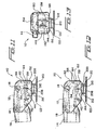
- FIGURE 11 is a schematic, side elevation of the airbag inflation nozzle assembly mounted upon the free end portion of the airbag inflation valve body with camming locking button is disposed in its UNLOCKED position;
- FIGURE 12 is a schematic, side elevation corresponding to that of FIGURE 11, with the camming locking button is disposed at its LOCKED position; and,
- FIGURE 13 is an end elevation of the airbag inflation nozzle assembly mounted upon the free end portion of the airbag inflation valve body and wherein the camming locking button is disposed at its LOCKED position.
-
- Referring now to the drawings, and more particularly to FIGURES 2 and 3 thereof, the new and improved airbag inflation nozzle assembly, which has been constructed in accordance with the teachings and principles of the present invention, is disclosed and is generally indicated by the
reference character 110. The airbaginflation nozzle assembly 110 is relatively simple in structure in that the same substantially comprises only three operative components comprising an airbaginflation assembly housing 112, an airbag inflationassembly nozzle member 114, and acamming locking button 116. Thenozzle member 114 is adapted to be mounted upon thehousing 112 by means of apivot pin 118 such that, as will become more apparent hereinafter, when thenozzle member 114 is mounted upon thehousing 112, thenozzle member 114 can undergo or experience limited pivotal movement relative to thehousing 112 between a first DISENGAGED and UNLOCKED position with respect to the tubular inflationvalve body member 120 of an airbaginflation valve assembly 122, as disclosed within FIGURE 11, and a second ENGAGED and LOCKED position with respect to the tubular inflationvalve body member 120 of the airbaginflation valve assembly 122, as disclosed within FIGURES 12 and 13, so as to move the valve stem portion, not shown, of theinflation valve assembly 122 to an OPENED position and thereby enable inflation of the cargo airbag to which theinflation valve assembly 122 is operatively connected. - With additional reference now being made to FIGURES 4 and 5, the details of the airbag
inflation nozzle member 114 will be disclosed. More particularly, it is seen that the airbaginflation nozzle member 114 comprises a first enlargedtubular end portion 124 which is internally tapped or threaded as at 126 so as to facilitate the threaded attachment of an air hose, not shown1 thereto by means of which a supply of compressed air can be transmitted to the airbaginflation nozzle member 114 for ultimate transmission to the airbaginflation valve assembly 122.Tubular end portion 124 ofnozzle member 114 is fluidically connected to afluid passageway 128 which is coaxially oriented with respect to thetubular end portion 124, and it is seen that thefluid passageway 128 extends axially through anelongated body portion 130 of thenozzle member 114. Theaxial fluid passageway 128 is, in turn, fluidically connected to a transversely or radially orientedfluid passageway 132 which is defined within anozzle tip portion 134 of thenozzle member 114. Thenozzle tip portion 134 comprises an annularlyrecessed portion 136 defined between an annular flangeddistal end portion 138 and ashoulder portion 140, and an 0-ring seal member 142, as seen in FIGURES 11-13, is adapted to be captured between the flangeddistal end portion 138 and theshoulder portion 140 so as to be seated within the annularly recessedportion 136. It is to be noted, as may best be appreciated from FIGURE 12, that the diametrical extent of the flangeddistal end portion 138 of thenozzle tip portion 134 is less than the diametrical extent of the tubulardistal end portion 144 of the tubular inflationvalve body member 120 of the airbaginflation valve assembly 122. In this manner, when thenozzle member 114 is pivoted aboutpivot pin 118 so as to be disposed at its ENGAGED position with respect to the tubular inflationvalve body member 120 of the airbaginflation valve assembly 122, thedistal end portion 138 of thenozzle tip portion 134 will be disposed internally within thedistal end portion 144 of thevalve body member 120 so as to actuate the valve stem member, not shown, of thevalve assembly 122, while the 0-ring member 142 will be seated upon the external periphery of thedistal end portion 144 of thevalve body member 120. - With reference now being additionally made to FIGURES 7-9, it is seen that the airbag
inflation assembly housing 112 comprises anupper wall 146, a pair of oppositely disposed side walls 148,150 integral with theupper wall 146, and afront end wall 152 integral with theupper wall 146 and the pair of oppositely disposed side walls 148,150. It is thus apparent that the bottom section of theassembly housing 112, disposed opposite theupper wall 146, as well as the rear end portion of theassembly housing 112, disposed opposite thefront end wall 152, are open so as to permit the insertion therewithin of the airbag inflationassembly nozzle member 114. More particularly, it is additionally seen that an arcuatelyrecessed portion 154 is defined within the rear end portion of theupper wall 146 and the upper end portions of each one of the oppositely disposed side walls 148,150, as best seen in, or appreciated from, FIGURE 13, so as to effectively provide a seat for the enlargedtubular end portion 124 of thenozzle member 114, as best seen in FIGURES 11 and 12, when thenozzle member 114 is mounted within theassembly housing 112 and, in particular, when thenozzle member 114 is moved to, and disposed at, its LOCKED and ENGAGED position with respect to thevalve body member 120 of the airbaginflation valve assembly 122. - In connection with the mounting or disposition. of the
nozzle member 114 within thehousing 112, it is also appreciated that the forward region of the enlargedtubular end portion 124 of thenozzle member 114 is provided with athroughbore 156 as best seen in FIGURES 4 and 5, and that each one of the side walls 148,150 of thehousing 112 is respectively provided with a through-bore 158,160. Through-bores 158,160 are adapted to be coaxially aligned with the through-bore 156 of thenozzle member 114, and in this. manner, wherein thepivot pin 118 is inserted through and secured within the side walls 148,150 of thehousing 112, thenozzle member 114 is pivotally mounted within thehousing 112 so as to be movable between its atorenoted first DISENGAGED and UNLOCKED position, arid its second ENGAGED and LOCKED position. As can be additionally appreciated from FIGURES 7-9, as well as FIGURES 11 and 12, it is further seen that a substantially rectangularly configuredrecessed region 162 is defined within thefront end wall 152 of the airbaginflation assembly housing 112, and accordingly, ashoulder portion 164 is provided within. thefront end wall 152. As can best be seen from FIGURES 4 and 5, as well as FIGURES 11 and 12, theforward end section 166 of theelongated body portion 130 of thenozzle member 114 protrudes or extends beyond that section of thenozzle tip portion 134 within which theshoulder portion 140 is provided so as to define alug 168 which is adapted to engage and be seated uponshoulder portion 164 of recessedregion 162 of thehousing 112 when thenozzle member 114 is moved downwardly from its DISENGAGED and UNLOCKED position as shown in FIGURE 11 to its ENGAGED and LOCKED position as shown in FIGURE 12. In this manner, thenozzle member 114 is fixedly retained at its ENGAGED and LOCKED position with respect to thevalve body member 120 of theinflation valve assembly 122, and in particular with respect to thedistal end portion 144 of thevalve body member 120, so as to ensure proper actuation of the valve stem member, not shown, of thevalve assembly 122 and the subsequent inflation of the airbag. - In order to in fact achieve the pivotal movement of the
nozzle member 114 from its DISENGAGED and UNLOCKED position to its ENGAGED and LOCKED position with respect to thevalve body member 120 of theinflation valve assembly 122, and. furthermore, in order to fixedly retain thenozzle member 114 at its ENGAGED and LOCKED position with respect to thevalve body member 120 of theinflation valve assembly 122, the airbaginflation nozzle assembly 110 of the present invention is provided with the unique and novel structure comprising the aforenotedcamming locking button 116 which is shown in detail in FIGURE 10. As can best be appreciated from FIGURES 7-9, the side walls 148,150 of thehousing 112 are respectively provided with through-bores 170,172 through which opposite ends of thecamming locking button 116 are adapted to be movably disposed. The through-bores 170,172 have substantially circular configurations, except that the uppermost portion of each through-bore 170,172 has a flattened or planar section, as shown, for example, at 174 in FIGURE 8 in connection with through-bore 172. - The
camming locking button 116 has a similar, substantially circular cross-sectional configuration, except that the uppermost portion of thecamming locking button 116 is likewise flattened or planar as indicated at 176 in FIGURE 10. The flattened or planar sections of through-bores 170,172 accordingly match and accommodate the similarly flattened or planaruppermost section 176 of thecamming locking button 116, and in this manner, rotational movement of thecamming locking button 116 is effectively prevented such that movement of thecamming locking button 116 within the through-bores 170,172, and between the UNLOCKED and LOCKED positions of thecamming locking button 116, is solely reciprocal and. linear. It is further noted, as best seen in FIGURE 7, that theupper wall 146 of thehousing 112 is also provided with a planar, recessedgroove 178 which in effect is a continuation of the flattened or planar sections of the through-bores 170,172 defined within the side walls 148,150 of thehousing 112, and in this manner, thecamming locking button 116 is linearly guided during its reciprocal movements between the UNLOCKED and LOCKED positions. - Continuing further, in order to achieve the UNLOCKED and LOCKED states or positions of the
camming locking button 116 with respect to theelongated body portion 130 of thenozzle member 114, and in turn, in order to achieve the UNLOCKED and LOCKED states or positions of theelongated body portion 130 of thenozzle member 114, and in particular thenozzle tip portion 134 thereof, with respect to the tubular inflationvalve body member 120 of the airbaginflation valve assembly 122, the upper forward surface section of theelongated body portion 130 of thenozzle member 114 is seen to comprise, as best seen in FIGURE 6, an uppermost, horizontally disposedplanar surface section 180 and a pair of downwardly inclined surface sections 182,184 disposed upon opposite sides of theplanar surface section 180. In a similar manner, as can best be appreciated from FIGURE 10, the undersurface portion of thecamming locking button 116 is provided with a vertically stepped recessed region comprising a first upper, horizontally disposedplanar surface section 186 and a pair of downwardly inclined surface sections 188,190 disposed upon opposite sides of the first upperplanar surface section 186. The undersurface recessed portion of thecamming locking button 116 is also provided with a second lower, horizontally disposedplanar surface 192, and a third downwardlyinclined surface section 194. It can therefore be readily appreciated. that when thecamming locking button 116 is linearly moved toward the right as seen in FIGURE 10 and in accordance with the arrow designated UNLOCKED such that thecamming locking button 116 is effectively disposed at its UNLOCKED position with respect to thenozzle member 114, the planar andinclined surface sections nozzle member 114 will be accommodated within the recessed undersurface region of thecamming locking button 116 as defined by the corresponding planar and inclined surface sections 186,188, and 190 whereby thenozzle member 114 is free to achieve its pivoted UNLOCKED and DISENGAGED state with respect to thevalve body member 120 of theinflation valve assembly 122 as can be seen in FIGURE 11. - When, however, the
camming locking button 116 is linearly moved toward the left as seen in FIGURE 10 and in accordance with the arrow designated LOCKED such that thecamming locking button 116 is effectively disposed at its LOCKED position with respect to thenozzle member 114, theinclined surface section 190 will forcefully engage theinclined surface section 184 of thenozzle member 114 and cause the same to effectively move downwardly along theinclined surface section 190 of thecamming locking button 116 until the second lower, horizontally disposedplanar surface 192 can be disposed atop the upperplanar surface section 180 of thenozzle member 114 and the thirdinclined surface section 194 of thecamming locking button 116 is disposed in engaged. contact with theinclined surface section 184 of thenozzle member 114 as can also be appreciated from FIGURE 13. As a result of such transverse linear movement of thecamming locking button 116, thenozzle member 114 has now been pivotally moved downwardly from its UNLOCKED and DISENGAGED state with respect to thevalve body member 120 of theinflation valve assembly 122 as shown in FIGURE 11 to its LOCKED and ENGAGED state with respect to thevalve body member 120 of theinflation valve assembly 122 as shown in FIGURE 12 whereby inflation of the inflatable airbag can be achieved. It is to be noted that when thecamming locking button 116 is moved from its UNLOCKED position to its LOCKED position, and as a result of the aforenoted engagement of the second lower, horizontally disposedplanar surface 192 with the upperplanar surface section 180 of thenozzle member 114, as well as the engagement of the thirdinclined surface section 194 of thecamming locking button 116 with theinclined surface section 184 of thenozzle member 114, not only can the operator personnel visually see that thecamming locking button 116 has been moved from its UNLOCKED position to its LOCKED position as a result of opposite end portions of thecamming locking button 116 projecting outwardly from the opposite side walls 148,150 of thehousing 112 depending upon the disposition of thecamming locking button 116 at its UNLOCKED and LOCKED positions, but in addition, the operator can also hear an audible click or snap-engagement sound as well as sense the attainment of the LOCKED state of thecamming locking button 116 in a tactile sense. - A last significant feature of the
airbag inflation assembly 110 as constructed in accordance with the teachings and principles of the present invention resides in the provision of structure therewithin for automatically achieving the proper disposition or positioning of theairbag inflation housing 112 and the airbaginflation nozzle member 114 with respect or relative to thevalve body member 120 of theinflation valve assembly 122 when the airbaginflation nozzle assembly 110 is being mounted upon thevalve body member 120 of theinflation valve assembly 122 so as to always ensure coaxial alignment of the airbaginflation nozzle member 114 with respect to thevalve body member 120 of theinflation valve assembly 122 and the consequent proper inflation of the airbag. More particularly, as can best be appreciated from FIGURES 7-9, each one of the side walls 148,150 of thehousing 112 is provided, at its lowermost end portion, with a transversely inwardly extending flanged portion 195,198, and in a similar manner, theend wall 152 is provided, at its lowermost end portion, with an axially inwardly extendingflanged portion 200 wherein theflanged portions 196, 198,200 are continuous and integral with each other so as to effectively define a substantially U-shaped ledge having side ledge portions 202,204, and anend ledge portion 206. - It can therefore be appreciated that when the air-bag
inflation nozzle assembly 110 is being mounted upon thevalve body member 120 of theinflation valve assembly 122, the side walls 14,150 of thehousing 112 effectively define an open-endedslot 207 within which thevalve body member 120 can be inserted and the ledge portions 202,204 will effectively serve as rail members upon which the lowerannular edge portion 208 of thedistal end portion 144 of the tubular inflationvalve body member 120 will ride. As best seen in FIGURES 11-13, an annularly recessedregion 210 is also defined between thedistal end portion 144 of thevalve body member 120 and a secondflanged portion 212 ofvalve body member 120 which is adapted to engage the external surface of the inflatable airbag, not shown, whenvalve body member 120 is mounted upon the airbag. In this manner, when the endflanged portion 200 encounters the annularly recessedregion 210 of thevalve body member 120, not only will the lowerannular edge portion 208 of thedistal end portion 144 of thevalve body member 120 be disposed upon theend ledge portion 206, but in addition, the relative movement of the airbaginflation assembly housing 112 will effectively be arrested whereby thenozzle tip portion 134 will be properly coaxially aligned with respect to thevalve body member 120 such that thenozzle tip portion 134 can be disposed internally within thedistal end portion 144 of thevalve body member 120 and thereby actuate the valve stem, not shown, of theinflation valve assembly 122 to it OPENED position. As is also best seen, for example, from FIGURE 12, when thenozzle tip portion 134 is disposed internally within thedistal end portion 144 of thevalve body member 120 so as to actuate the valve stem, not shown, of theinflation valve assembly 122, the 0-ring member 142 will be seated upon the external periphery of thedistal end portion 144 ofvalve body member 120 in a somewhat compressed state so as to achieve its desired tight sealing function. - Thus, it may be seen that in accordance with the teachings and principles of the present invention, a relatively simple airbag inflation nozzle assembly has been developed and constructed wherein the inflation nozzle assembly is easy to manipulate and use, wherein the inflation nozzle assembly is easy to mount upon the inflation valve assembly of the airbag to be inflated, wherein the inflation nozzle assembly comprises structure for always ensuring that the nozzle tip portion will be properly coaxially aligned with respect to the inflation valve assembly upon the airbag so as to properly actuate the valve stem component thereof and thereby achieve inflation of the airbag, and wherein the inflation nozzle assembly can be easily disposed within UNLOCKED and LOCKED states with respect to the inflation valve body member of the inflation valve assembly. it is further noted that as a result of the provision of the camming locking button upon the housing for easily achieving the UNLOCKED and LOCKED states, the operator personnel are also readily provided with visual, audible, and tactile means for indicating the achievement of the LOCKED state of the assembly.
Claims (9)
- An inflation nozzle assembly (110) for inflating an article having an inflation valve (212) mounted thereon, comprising:a housing (112);an air inflation nozzle (114) having a first end portion (126) adapted for connection to a source of compressed air so as to receive a supply of compressed air from the source, and a second end portion comprising a nozzle tip (138) for mating with an inflation valve (212);first means (118) movably mounting said air inflation nozzle (114) upon said housing (112) between a first position at which said air inflation nozzle (114) is fluidically disengaged from the inflation valve (212) such that the article cannot be inflated, and a second position at which said inflation nozzle (114) is, in use, fluidically engaged with the inflation valve (212) so that the article can be inflated;second means (116) movably mounted upon said housing (112) between a first position at which said second means permits said air inflation nozzle (114) to occupy said first position, and a second position at which said second means (116) causes said air inflation nozzle (114) to move to said second position at which said inflation nozzle (114) is, in use, fluidically engaged with the inflation valve (212) so that the article is inflated.
- An assembly according to claim 1, wherein:said, housing (112) comprises a pair of oppositely disposed side walls (148,150), and an end wall (150); and,said end wall comprises (152) a flanged portion (200) for engaging the inflation valve (212) as said air inflation nozzle assembly (110) is operatively mated with the inflation valve (212) so as to coaxially align the inflation valve (212) with said inflation nozzle tip (138) and thereby ensure proper inflation of the article to be inflated.
- An assembly according to claim 2, wherein:said pair of oppositely disposed side walls (148,150) of said housing (110) include flanged portions defining a pair of oppositely disposed rail members (196,198) upon which the inflation valve (212) can be movably supported when said air inflation nozzle assembly (110) is operatively mated with the inflation valve (212).
- An assembly according to any one of the preceding claims, wherein:said. first means movably mounting said air inflation nozzle upon said housing comprises a pivot pin (118) for pivotably mounting said air inflation nozzle (114) upon said housing (112).
- An assembly according to any one of the preceding claims, wherein:said second means comprises a camming button (116) for engaging said air inflation nozzle (114) and moving said air inflation nozzle (114) from said first position, as said camming button (116) is moved from its first position to its second position.
- An assembly according to claim 5, wherein:wherein said camming button (116) is movable transversely, with respect to said longitudinal extent of said air inflation nozzle (114), between said first and second positions.said air inflation nozzle (114) has a longitudinal extent; and,
- An assembly according to claim 6, wherein:said camming button (116) comprises a vertically stepped recessed portion (186,192) such that when said camming button (116) is moved transversely to said first position, a first upper section (186) of said vertically stepped recessed portion is aligned with respect to said air inflation nozzle (114) so as to permit said air inflation nozzle to be disposed at said first position whereas when said camming button (116) is moved transversely, said second position, a second lower section (192) of said vertically stepped recessed portion is aligned with respect to said air inflation nozzle (114) so as to cause said air inflation nozzle (114) to be disposed at said second position.
- An assembly according to claim 7, wherein:said air inflation nozzle (114) comprises a planar surface portion (180) and an inclined surface portion (184) disposed upon a lateral side of said planar surface portion; and,said vertically stepped recessed portion of said camming button comprises a first upper planar surface (186), and a first inclined surface (190) disposed upon a lateral side of said first upper planar surface (186), for respectively engaging said planar surface portion (180) and said inclined surface portion (184) of said air inflation nozzle (114) when said camming button (118) is disposed at said first position, and a second lower planar surface (192), and a second inclined surface (194) disposed upon a lateral side of said second lower planar surface, for respectively engaging said planar surface portion (180) and said inclined surface portion (184) of said air inflation nozzle when said camming button (118) is disposed at said second position.
- An assembly according to any one of the preceding claims, wherein said article having an inflation valve (212) is a cargo airbag.
Applications Claiming Priority (2)
| Application Number | Priority Date | Filing Date | Title |
|---|---|---|---|
| US15786 | 2001-12-17 | ||
| US10/015,786 US6676042B2 (en) | 2001-12-17 | 2001-12-17 | Airbag inflation nozzle assembly |
Publications (2)
| Publication Number | Publication Date |
|---|---|
| EP1319883A1 true EP1319883A1 (en) | 2003-06-18 |
| EP1319883B1 EP1319883B1 (en) | 2005-10-26 |
Family
ID=21773626
Family Applications (1)
| Application Number | Title | Priority Date | Filing Date |
|---|---|---|---|
| EP02258465A Expired - Lifetime EP1319883B1 (en) | 2001-12-17 | 2002-12-09 | Inflation nozzle assembly |
Country Status (7)
| Country | Link |
|---|---|
| US (1) | US6676042B2 (en) |
| EP (1) | EP1319883B1 (en) |
| JP (1) | JP4122214B2 (en) |
| CN (1) | CN1272546C (en) |
| CA (1) | CA2414859C (en) |
| DE (1) | DE60206870T2 (en) |
| MX (1) | MXPA02012514A (en) |
Cited By (2)
| Publication number | Priority date | Publication date | Assignee | Title |
|---|---|---|---|---|
| ITMI20101114A1 (en) * | 2010-06-18 | 2011-12-19 | Bridgeport S R L | QUICK CONNECTOR FOR INFLATING VALVE OF A TIRE OR OTHER PRESSURE CONTAINER |
| EP4134275A1 (en) * | 2021-08-10 | 2023-02-15 | ABP Airbag Production Kft. | Airbag valve system |
Families Citing this family (15)
| Publication number | Priority date | Publication date | Assignee | Title |
|---|---|---|---|---|
| US7770612B1 (en) * | 2009-09-04 | 2010-08-10 | Jimmy Earle Brown | Pressure-actuated air gun |
| US8235632B2 (en) | 2010-05-14 | 2012-08-07 | Illinois Tool Works Inc. | Cargo bag valve deflector |
| TW201142147A (en) * | 2010-05-25 | 2011-12-01 | Shu-Mu Wu | Easy operated pull-rod nozzle |
| US10562436B2 (en) | 2013-07-30 | 2020-02-18 | Signode Industrial Group Llc | Portable dunnage bag inflator |
| CN111492163B (en) | 2017-10-27 | 2022-05-13 | 斯托巴克印度私人有限公司 | Inflation valve |
| US11300225B1 (en) | 2018-01-24 | 2022-04-12 | Edgar G. Ashmead | Valve-coupler actuating system |
| US10760708B1 (en) | 2018-01-24 | 2020-09-01 | Edgar G. Ashmead | Valve-coupler actuating system |
| CN110385320A (en) * | 2018-04-22 | 2019-10-29 | 张佳 | Empty bottle cleaner for inner wall |
| US11118368B2 (en) * | 2018-06-22 | 2021-09-14 | Hayward Industries, Inc. | Laminar water feature |
| AU2019340606B2 (en) | 2018-09-12 | 2022-03-17 | Signode India Limited | Inflator with automatic shut-off functionality |
| USD904461S1 (en) | 2018-09-21 | 2020-12-08 | Stopak India Pvt. Ltd. | Inflator |
| USD928841S1 (en) | 2019-04-10 | 2021-08-24 | Signode Industrial Group Llc | Inflator |
| US11654859B2 (en) * | 2019-07-08 | 2023-05-23 | Illinois Tool Works Inc. | Filter diffuser |
| USD943636S1 (en) | 2020-05-26 | 2022-02-15 | Signode Industrial Group Llc | Inflator |
| CN117339786B (en) * | 2023-12-04 | 2024-02-13 | 四川省林业和草原调查规划院(四川省林业和草原生态环境监测中心) | Forestry is trunk lime spraying device for pest control |
Citations (4)
| Publication number | Priority date | Publication date | Assignee | Title |
|---|---|---|---|---|
| GB573890A (en) * | 1943-12-24 | 1945-12-11 | Tecalemit Ltd | Improvements in pipe joints or connectors |
| FR972884A (en) * | 1941-05-31 | 1951-02-05 | Variable orientation hooking claw for grease gun connection | |
| FR1405726A (en) * | 1963-08-23 | 1965-07-09 | Shell Int Research | Quick-release hose connector, especially for vessels containing gas or liquefied gas |
| US5042541A (en) * | 1990-06-05 | 1991-08-27 | Shippers Paper Products Company | Inflation nozzle for cargo air bag |
Family Cites Families (6)
| Publication number | Priority date | Publication date | Assignee | Title |
|---|---|---|---|---|
| JPS4821456B1 (en) * | 1970-12-01 | 1973-06-28 | ||
| JPS4858533A (en) * | 1971-11-22 | 1973-08-16 | ||
| US5772238A (en) * | 1995-12-12 | 1998-06-30 | Automotive Technologies International Inc. | Efficient airbag module |
| US5484163A (en) * | 1994-02-17 | 1996-01-16 | Trw Vehicle Safety Systems Inc. | Vehicle occupant restraint apparatus |
| GB2306556A (en) * | 1995-11-02 | 1997-05-07 | Luke Lo | Air bag clip |
| US5839488A (en) | 1997-05-29 | 1998-11-24 | Peters; Gerald L. | Hands-off low-air-loss quick-connect quick-disconnect fast-fill dunnage bag filling valve-nozzle assembly & system |
-
2001
- 2001-12-17 US US10/015,786 patent/US6676042B2/en not_active Expired - Fee Related
-
2002
- 2002-12-09 EP EP02258465A patent/EP1319883B1/en not_active Expired - Lifetime
- 2002-12-09 DE DE60206870T patent/DE60206870T2/en not_active Expired - Fee Related
- 2002-12-16 CA CA002414859A patent/CA2414859C/en not_active Expired - Fee Related
- 2002-12-16 MX MXPA02012514A patent/MXPA02012514A/en active IP Right Grant
- 2002-12-17 CN CNB021566542A patent/CN1272546C/en not_active Expired - Fee Related
- 2002-12-17 JP JP2002365270A patent/JP4122214B2/en not_active Expired - Fee Related
Patent Citations (4)
| Publication number | Priority date | Publication date | Assignee | Title |
|---|---|---|---|---|
| FR972884A (en) * | 1941-05-31 | 1951-02-05 | Variable orientation hooking claw for grease gun connection | |
| GB573890A (en) * | 1943-12-24 | 1945-12-11 | Tecalemit Ltd | Improvements in pipe joints or connectors |
| FR1405726A (en) * | 1963-08-23 | 1965-07-09 | Shell Int Research | Quick-release hose connector, especially for vessels containing gas or liquefied gas |
| US5042541A (en) * | 1990-06-05 | 1991-08-27 | Shippers Paper Products Company | Inflation nozzle for cargo air bag |
Cited By (3)
| Publication number | Priority date | Publication date | Assignee | Title |
|---|---|---|---|---|
| ITMI20101114A1 (en) * | 2010-06-18 | 2011-12-19 | Bridgeport S R L | QUICK CONNECTOR FOR INFLATING VALVE OF A TIRE OR OTHER PRESSURE CONTAINER |
| EP2397382A1 (en) * | 2010-06-18 | 2011-12-21 | Bridgeport S.R.L. | Quick connector for inflation valve of a tyre |
| EP4134275A1 (en) * | 2021-08-10 | 2023-02-15 | ABP Airbag Production Kft. | Airbag valve system |
Also Published As
| Publication number | Publication date |
|---|---|
| DE60206870T2 (en) | 2006-04-20 |
| JP4122214B2 (en) | 2008-07-23 |
| MXPA02012514A (en) | 2004-12-13 |
| US20030111554A1 (en) | 2003-06-19 |
| US6676042B2 (en) | 2004-01-13 |
| DE60206870D1 (en) | 2005-12-01 |
| CA2414859A1 (en) | 2003-06-17 |
| EP1319883B1 (en) | 2005-10-26 |
| JP2004003432A (en) | 2004-01-08 |
| CN1427155A (en) | 2003-07-02 |
| CA2414859C (en) | 2005-10-18 |
| CN1272546C (en) | 2006-08-30 |
Similar Documents
| Publication | Publication Date | Title |
|---|---|---|
| EP1319883B1 (en) | Inflation nozzle assembly | |
| US7610929B2 (en) | Air bag inflation/ deflation system | |
| US5082244A (en) | Cargo air bag inflation valve and inflator combination | |
| US6823905B1 (en) | Inflation valve assembly for a dunnage or cargo air bag | |
| CN108662215B (en) | Valve with a valve body | |
| US7913724B2 (en) | Inflation device | |
| US7793687B2 (en) | Inflation/deflation adaptor assembly for inflating and deflating inflatable cargo dunnage bags | |
| US5839488A (en) | Hands-off low-air-loss quick-connect quick-disconnect fast-fill dunnage bag filling valve-nozzle assembly & system | |
| US7980799B1 (en) | Air bag inflator | |
| EP0466312B1 (en) | Inflation nozzle | |
| EP2771601B1 (en) | Valve for inflation and deflation of air bags and method of use thereof | |
| WO2008110981A1 (en) | Inflation valve | |
| CA2761693A1 (en) | Inflation device | |
| EP2569184B1 (en) | Cargo bag valve deflector | |
| US20160186875A1 (en) | Inflation Valve | |
| WO2019036530A1 (en) | Automated trailer pneumatic inflation system | |
| AU2005201624B2 (en) | Air bag inflation/deflation system | |
| WO2008099237A1 (en) | Inflation device | |
| WO2015159211A1 (en) | Inflator arrangement |
Legal Events
| Date | Code | Title | Description |
|---|---|---|---|
| PUAI | Public reference made under article 153(3) epc to a published international application that has entered the european phase |
Free format text: ORIGINAL CODE: 0009012 |
|
| AK | Designated contracting states |
Designated state(s): AT BE BG CH CY CZ DE DK EE ES FI FR GB GR IE IT LI LU MC NL PT SE SI SK TR |
|
| AX | Request for extension of the european patent |
Extension state: AL LT LV MK RO |
|
| 17P | Request for examination filed |
Effective date: 20031208 |
|
| AKX | Designation fees paid |
Designated state(s): BE DE FR GB |
|
| 17Q | First examination report despatched |
Effective date: 20050204 |
|
| GRAP | Despatch of communication of intention to grant a patent |
Free format text: ORIGINAL CODE: EPIDOSNIGR1 |
|
| GRAS | Grant fee paid |
Free format text: ORIGINAL CODE: EPIDOSNIGR3 |
|
| GRAA | (expected) grant |
Free format text: ORIGINAL CODE: 0009210 |
|
| AK | Designated contracting states |
Kind code of ref document: B1 Designated state(s): BE DE FR GB |
|
| REG | Reference to a national code |
Ref country code: GB Ref legal event code: FG4D |
|
| REF | Corresponds to: |
Ref document number: 60206870 Country of ref document: DE Date of ref document: 20051201 Kind code of ref document: P |
|
| ET | Fr: translation filed | ||
| PLBE | No opposition filed within time limit |
Free format text: ORIGINAL CODE: 0009261 |
|
| STAA | Information on the status of an ep patent application or granted ep patent |
Free format text: STATUS: NO OPPOSITION FILED WITHIN TIME LIMIT |
|
| 26N | No opposition filed |
Effective date: 20060727 |
|
| PGFP | Annual fee paid to national office [announced via postgrant information from national office to epo] |
Ref country code: DE Payment date: 20090202 Year of fee payment: 7 |
|
| PGFP | Annual fee paid to national office [announced via postgrant information from national office to epo] |
Ref country code: GB Payment date: 20081229 Year of fee payment: 7 |
|
| PGFP | Annual fee paid to national office [announced via postgrant information from national office to epo] |
Ref country code: BE Payment date: 20090202 Year of fee payment: 7 |
|
| PGFP | Annual fee paid to national office [announced via postgrant information from national office to epo] |
Ref country code: FR Payment date: 20081217 Year of fee payment: 7 |
|
| BERE | Be: lapsed |
Owner name: ILLINOIS *TOOL WORKS INC. Effective date: 20091231 |
|
| GBPC | Gb: european patent ceased through non-payment of renewal fee |
Effective date: 20091209 |
|
| REG | Reference to a national code |
Ref country code: FR Ref legal event code: ST Effective date: 20100831 |
|
| PG25 | Lapsed in a contracting state [announced via postgrant information from national office to epo] |
Ref country code: FR Free format text: LAPSE BECAUSE OF NON-PAYMENT OF DUE FEES Effective date: 20091231 Ref country code: BE Free format text: LAPSE BECAUSE OF NON-PAYMENT OF DUE FEES Effective date: 20091231 |
|
| PG25 | Lapsed in a contracting state [announced via postgrant information from national office to epo] |
Ref country code: DE Free format text: LAPSE BECAUSE OF NON-PAYMENT OF DUE FEES Effective date: 20100701 |
|
| PG25 | Lapsed in a contracting state [announced via postgrant information from national office to epo] |
Ref country code: GB Free format text: LAPSE BECAUSE OF NON-PAYMENT OF DUE FEES Effective date: 20091209 |