EP1319880B1 - Method of forming a connector on the end of a respiratory conduit - Google Patents
Method of forming a connector on the end of a respiratory conduit Download PDFInfo
- Publication number
- EP1319880B1 EP1319880B1 EP02027857A EP02027857A EP1319880B1 EP 1319880 B1 EP1319880 B1 EP 1319880B1 EP 02027857 A EP02027857 A EP 02027857A EP 02027857 A EP02027857 A EP 02027857A EP 1319880 B1 EP1319880 B1 EP 1319880B1
- Authority
- EP
- European Patent Office
- Prior art keywords
- conduit
- connector
- sleeve
- thread
- wall
- Prior art date
- Legal status (The legal status is an assumption and is not a legal conclusion. Google has not performed a legal analysis and makes no representation as to the accuracy of the status listed.)
- Expired - Lifetime
Links
- 238000000034 method Methods 0.000 title claims abstract description 21
- 230000000241 respiratory effect Effects 0.000 title 1
- 238000000465 moulding Methods 0.000 claims abstract description 14
- 239000011324 bead Substances 0.000 claims description 8
- 239000004020 conductor Substances 0.000 claims description 5
- 239000007789 gas Substances 0.000 abstract description 13
- 239000004033 plastic Substances 0.000 abstract description 12
- 229920003023 plastic Polymers 0.000 abstract description 12
- 238000009423 ventilation Methods 0.000 abstract description 10
- XLYOFNOQVPJJNP-UHFFFAOYSA-N water Substances O XLYOFNOQVPJJNP-UHFFFAOYSA-N 0.000 abstract description 8
- 238000002560 therapeutic procedure Methods 0.000 abstract description 5
- 239000003292 glue Substances 0.000 abstract description 3
- 230000008901 benefit Effects 0.000 abstract description 2
- 229920001169 thermoplastic Polymers 0.000 abstract 1
- 239000004416 thermosoftening plastic Substances 0.000 abstract 1
- 239000000463 material Substances 0.000 description 4
- 229910052751 metal Inorganic materials 0.000 description 3
- 239000002184 metal Substances 0.000 description 3
- 239000011295 pitch Substances 0.000 description 3
- 238000007789 sealing Methods 0.000 description 3
- 238000010438 heat treatment Methods 0.000 description 2
- 230000008569 process Effects 0.000 description 2
- 230000004044 response Effects 0.000 description 2
- 239000012815 thermoplastic material Substances 0.000 description 2
- 239000004698 Polyethylene Substances 0.000 description 1
- 206010063968 Upper airway resistance syndrome Diseases 0.000 description 1
- 239000000853 adhesive Substances 0.000 description 1
- 238000004026 adhesive bonding Methods 0.000 description 1
- 230000001070 adhesive effect Effects 0.000 description 1
- 239000004411 aluminium Substances 0.000 description 1
- 229910052782 aluminium Inorganic materials 0.000 description 1
- XAGFODPZIPBFFR-UHFFFAOYSA-N aluminium Chemical compound [Al] XAGFODPZIPBFFR-UHFFFAOYSA-N 0.000 description 1
- 238000005452 bending Methods 0.000 description 1
- 230000006835 compression Effects 0.000 description 1
- 238000007906 compression Methods 0.000 description 1
- 230000005494 condensation Effects 0.000 description 1
- 238000009833 condensation Methods 0.000 description 1
- 238000010276 construction Methods 0.000 description 1
- 230000007423 decrease Effects 0.000 description 1
- 230000000694 effects Effects 0.000 description 1
- 239000012530 fluid Substances 0.000 description 1
- 230000006870 function Effects 0.000 description 1
- 239000012212 insulator Substances 0.000 description 1
- 230000001050 lubricating effect Effects 0.000 description 1
- 239000000203 mixture Substances 0.000 description 1
- 230000037361 pathway Effects 0.000 description 1
- -1 polyethylene Polymers 0.000 description 1
- 229920000573 polyethylene Polymers 0.000 description 1
- 230000001105 regulatory effect Effects 0.000 description 1
- 201000002859 sleep apnea Diseases 0.000 description 1
- 229920002994 synthetic fiber Polymers 0.000 description 1
- 239000004758 synthetic textile Substances 0.000 description 1
Images


Classifications
-
- A—HUMAN NECESSITIES
- A61—MEDICAL OR VETERINARY SCIENCE; HYGIENE
- A61M—DEVICES FOR INTRODUCING MEDIA INTO, OR ONTO, THE BODY; DEVICES FOR TRANSDUCING BODY MEDIA OR FOR TAKING MEDIA FROM THE BODY; DEVICES FOR PRODUCING OR ENDING SLEEP OR STUPOR
- A61M16/00—Devices for influencing the respiratory system of patients by gas treatment, e.g. ventilators; Tracheal tubes
- A61M16/08—Bellows; Connecting tubes ; Water traps; Patient circuits
- A61M16/0816—Joints or connectors
-
- F—MECHANICAL ENGINEERING; LIGHTING; HEATING; WEAPONS; BLASTING
- F16—ENGINEERING ELEMENTS AND UNITS; GENERAL MEASURES FOR PRODUCING AND MAINTAINING EFFECTIVE FUNCTIONING OF MACHINES OR INSTALLATIONS; THERMAL INSULATION IN GENERAL
- F16L—PIPES; JOINTS OR FITTINGS FOR PIPES; SUPPORTS FOR PIPES, CABLES OR PROTECTIVE TUBING; MEANS FOR THERMAL INSULATION IN GENERAL
- F16L25/00—Construction or details of pipe joints not provided for in, or of interest apart from, groups F16L13/00 - F16L23/00
- F16L25/0036—Joints for corrugated pipes
-
- A—HUMAN NECESSITIES
- A61—MEDICAL OR VETERINARY SCIENCE; HYGIENE
- A61M—DEVICES FOR INTRODUCING MEDIA INTO, OR ONTO, THE BODY; DEVICES FOR TRANSDUCING BODY MEDIA OR FOR TAKING MEDIA FROM THE BODY; DEVICES FOR PRODUCING OR ENDING SLEEP OR STUPOR
- A61M16/00—Devices for influencing the respiratory system of patients by gas treatment, e.g. ventilators; Tracheal tubes
- A61M16/08—Bellows; Connecting tubes ; Water traps; Patient circuits
- A61M16/0875—Connecting tubes
-
- A—HUMAN NECESSITIES
- A61—MEDICAL OR VETERINARY SCIENCE; HYGIENE
- A61M—DEVICES FOR INTRODUCING MEDIA INTO, OR ONTO, THE BODY; DEVICES FOR TRANSDUCING BODY MEDIA OR FOR TAKING MEDIA FROM THE BODY; DEVICES FOR PRODUCING OR ENDING SLEEP OR STUPOR
- A61M16/00—Devices for influencing the respiratory system of patients by gas treatment, e.g. ventilators; Tracheal tubes
- A61M16/10—Preparation of respiratory gases or vapours
- A61M16/14—Preparation of respiratory gases or vapours by mixing different fluids, one of them being in a liquid phase
- A61M16/16—Devices to humidify the respiration air
Definitions
- the present invention relates to a method of forming a connector on the end of a flexible conduit.
- CPAP Continuous Positive Airway Pressure
- VPAP Vehicle Positive Airway Pressure
- BiPAP Bi-level Positive Airway Pressure
- the delivery of gases tithe patient requires, in the very least, a nose, mouth, or face mask fitted to the patient with a connection via a flexible gases delivery conduit to a gases flow generator.
- One requirement of the delivery conduit is to provide humidified air at a particular pressure to the patient, via the mask.
- the conduit therefore requires connectors at each end that provide effective sealing and connection of the conduit to the mask, humidifier and /or air flow generator of the positive pressure ventilation system, so that there is no or low pressure loss along the delivery conduit.
- US Patent No 5 848 223 discloses a conduit that is a tube having a helically wound support bead between inner and outer walls.
- a helically wrapped electrical resistance heating conduit is disposed adjacent to the inner wall, in good heat transfer relation to fluid and/or air that flows within the tube. The majority of these connections are made by threading the connector onto the conduit and then gluing the connector to the conduit.
- US Patent 3963856 discloses a connection or fitting that is bonded to a conduit or tubing.
- the fitting has an internal thread that is simply threaded onto the external bead or wall of the tubing.
- the bond may be adhesive or of the heat seal type.
- a further other commonly used method is to mould the connector directly onto the conduit.
- a further method used is the over moulding of the connector onto a clip and conduit, where the clip is attached to one end of the conduit.
- the clip is partially annular in shape and is placed over and in between a cut made in the outer wall of the conduit, therefore the clip sits in between the bead.
- a connector is then moulded around the clip and conduit. With this method the conduit is often compressed, and with high temperatures and pressures used during moulding excess plastic flashing can be forced from the mould across the connector to the outer wall of the tubing.
- Plastic flashings and hot plastic may during moulding touch the outer wall of the conduit at the connector interface causing damage to the tubing walls, leading to water and air seepage into and out of the conduit.
- FR717210 discloses a metal tube with an external thread with a rubber covering, where one end is exposed to form a male fitting.
- This male fitting mates with a female part which consists of a metal pipe part with an internal thread completely covered by a rubber fitting which overlaps at each end.
- the male part extends into the female part and the external thread screws into the internal thread, the rubber coverings forming a seal.
- FR2717556 discloses a connector that is rigid at one end which has a thread.
- the flexible tube has at its end connecting to the connector constituted by longitudinal weft yam interlaced with a synthetic textile warp yam located in a helix.
- a part of the warp is metallic and is forcibly screwed onto the thread of the connector.
- the connector forms a nut and the tube forms a screw or vice versa.
- a cylindrical lip surrounding the connector threaded end covers the tube mounting end.
- the connector thread and the thread formed by the tube metal warp are of single or multiple threads.
- a plastic lubricating material for sticking and sealing the parts is located between the connector threads and the tube fitting part.
- the connector is entirely rigid and is fixed at its end opposite the tube by a flexible mounting sleeve.
- DE1 9800986 discloses a connecting piece where the intermediate connecting piece has a corrugated hose section, the end section of which is held in a seat in a polyethylene pipe section. A plastic sheath covers the pipe section and hose section over a predetermined length. O-rings are let into the corrugations between the seating surface and corrugated hose section.
- the present invention consists in a method of forming a connector as defined in claim 1.
- the preferred embodiment of the present invention relates to a method of forming an end connector onto a delivery conduit that may be used in medical apparatus or ventilation therapy systems.
- the connector allows for the delivery conduit to be connected to other apparatus in the ventilation system, such as, an air generator, humidifier or mask.
- the delivery conduit must be capable of providing air, usually humidified, to the patient at a particular pressure, in order for ventilation therapy to be successful.
- FIG. 1 A typical patient ventilation therapy system that uses such a flexible delivery conduit is shown in Figure 1 .
- a humidified positive pressure ventilation system is shown in which a patient 1 is receiving humidified and pressurised gases through a patient interface 2 connected to a humidified gases transportation pathway or delivery conduit 3.
- Delivery conduit 3 is connected to the outlet 4 of a humidification chamber 5, which contains a volume of water 6.
- Delivery conduit 3 usually contains heating means or heater wires (not shown), which heat the walls of the conduit to reduce condensation of humidified gases within the conduit.
- Humidification chamber 6 is preferably formed from a plastics material and may have a highly heat conductive base (for example an aluminium base) which is in direct contact with a heater plate 7 of humidifier 8.
- Humidifier 8 is provided with control means or electronic controller 9 which may comprise a microprocessor based controller executing computer software commands stored in associated memory
- Controller 9 receives input from sources such as user input means or dial 10 through which a user of the device may, for example, set a predetermined required value (preset value) of humidity or temperature of the gases supplied to patient 1.
- the controller may also receive input from other sources, for example temperature and/or flow velocity sensors 11 and 12 through connector 13 and heater plate temperature sensor 14.
- controller 9 determines when (or to what level) to energise heater plate 7 to heat the water 6 within humidification chamber 5.
- water vapour begins to fill the volume of the chamber above the water's surface and is passed out of the humidification chamber 5 outlet 4 with the flow of gases (for example air) provided from a gases supply means or blower 15 which enters the chamber through inlet 16, Exhaled gases from the patient's mouth are passed directly to ambient surroundings.
- gases for example air
- Blower 15 is provided with variable pressure regulating means or variable speed fan 21, which draws air or other gases through blower inlet 17.
- the speed of variable speed fan 21 is controlled by electronic controller 18 (or alternatively the function of controller 18 could be carried out by controller 9) in response to inputs from controller 9 and a user set predetermined required value (preset value) of pressure or fan speed via dial 19.
- a sleeve 22 having an internal surface 23 that is adapted for receiving a flexible conduit (indicated as 3 in Figure 1 ) is shown.
- the conduit is preferably a double-walled helically wound flexible conduit or tube as disclosed in US Patent No. 5848223 , but may be of other appropriate conduit construction.
- the internal surface 23 of the sleeve 22 has a thread 24 formed in it when moulded.
- the thread 24 is a complimentary size and shape to that of the outer surface of the conduit 3.
- the sleeve 22 is preferably moulded from a thermoplastic material similar to the material the connector is manufactured or moulded from, but it is appreciated that other similar plastics materials may be used to construct the sleeve.
- the sleeve thread 24 is a helical thread having two different pitches 27 and 28.
- the thread 24 is shown in Figure 3 as hidden detail.
- the start 25 of the thread 24 begins at the bottom of the sleeve 22 and ends 26 approximately two thirds up the height of the sleeve.
- the thread 24 consists of one and three-quarter rotations and has an inclining pitch 27 for one and a half rotations.
- the last quarter rotation 28 of the thread has no incline or decline.
- the ends of the thread 24 are also formed so as to taper into the inner surface of the sleeve 22; this makes it easier for a user to thread the sleeve onto the conduit.
- FIG. 4 and 5 illustrate the sleeve 22 in use and located about a flexible conduit 29.
- the conduit in this embodiment has an outer wall 30 and an inner wall 31 with electrical conductors (not shown) being disposed around the inner wall 31 with a support bead 32 surrounding the conductors and maintaining adhesion of the conductors to the inner wall.
- the support bead 32 has been heat bonded to the outside of the inner wall, this inner wall being a thin-walled tubular body.
- the outer wall is a ribbon applied over the wraps of the support bead spanning from one wrap to the next so as to define an outer wall for the conduit.
- the outer surface of the thread 24 abuts the outer wall 30 and, in the preferred form, causes a slight compression of the outer wall. As the thread 24 is slightly smaller in dimension than that of the outer wall 30 of the conduit 29, this causes there to be at tight fitting of the sleeve 22 about the conduit 29.
- the sleeve 22 is threaded onto one end of the conduit 29.
- a connector is then moulded over the conduit and sleeve as shown in Figure 6 .
- molten thermoplastic material is injected into the cavity between the sleeve 22 and the conduit 29, resulting in a seal being made between the sleeve 22 and conduit 29, so that a connector 33 is formed over the end of the conduit 29.
- the sleeve 22 becomes part of the inner surface of the connector 33 as it blends with the connector 33 during moulding. Furthermore, the sleeve 22 acts as a means to determine where to locate the connector 33 on the end of the conduit 29.
- the sleeve 22 may not be fully enclosed within the connector 33, but may extend slightly out of the end 34 of the connector 33. In this form the sleeve 22 provides enhanced effect in reducing the occurrence of plastics flashings across the conduit walls.
- the moulding of the connector 33 over the sleeve 22 and conduit 29 results in a seal between the conduit 29 and the connector 33 that prevents leakages in the conduit.
- the sleeve 22 acts to isolate the outer film layer 30 of the conduit 29 during over moulding.
- the threads spiral protrusions act as a stop to prevent molten plastic from flowing between the inner and outer walls 31, 30.
- the sealing of the connector 33 to the conduit 29 also prevents moisture from moving between the inner and outer walls 31, 30.
- the sleeve also acts as an insulator and prevents hot molten plastic from being in contact with the conduit during over moulding, preventing damage to the conduit
- the method of forming a connector on the end of a flexible conduit of the present invention has the advantage that it prevents the connector from loosening or breaking when the conduit is bent, pulled or stressed, which can occur in some cases where the connector is attached to the conduit using a bond, such as glue.
- the pitch of the thread on the sleeve is less than that provided by the outer wall and bead on the conduit, providing ease of assembly.
Landscapes
- Engineering & Computer Science (AREA)
- Health & Medical Sciences (AREA)
- General Engineering & Computer Science (AREA)
- General Health & Medical Sciences (AREA)
- Veterinary Medicine (AREA)
- Biomedical Technology (AREA)
- Heart & Thoracic Surgery (AREA)
- Hematology (AREA)
- Life Sciences & Earth Sciences (AREA)
- Animal Behavior & Ethology (AREA)
- Pulmonology (AREA)
- Public Health (AREA)
- Anesthesiology (AREA)
- Emergency Medicine (AREA)
- Mechanical Engineering (AREA)
- Rigid Pipes And Flexible Pipes (AREA)
- Pipe Accessories (AREA)
- Duct Arrangements (AREA)
- Infusion, Injection, And Reservoir Apparatuses (AREA)
- Measuring Fluid Pressure (AREA)
Abstract
Description
- The present invention relates to a method of forming a connector on the end of a flexible conduit.
- Administration of positive pressure ventilation is a common method of treating Obstructive Sleep Apnoea syndrome and Upper Airway Resistance syndrome. Some forms of delivery systems that can be used for ventilation therapy are; CPAP (Continuous Positive Airway Pressure), VPAP (Variable Positive Airway Pressures) and BiPAP (Bi-level Positive Airway Pressure)
- The delivery of gases tithe patient requires, in the very least, a nose, mouth, or face mask fitted to the patient with a connection via a flexible gases delivery conduit to a gases flow generator. One requirement of the delivery conduit is to provide humidified air at a particular pressure to the patient, via the mask. The conduit therefore requires connectors at each end that provide effective sealing and connection of the conduit to the mask, humidifier and /or air flow generator of the positive pressure ventilation system, so that there is no or low pressure loss along the delivery conduit.
- There are a variety of methods for fitting a connector to a flexible helically wound conduit, such as the tubing disclosed in
US . This patent discloses a conduit that is a tube having a helically wound support bead between inner and outer walls. A helically wrapped electrical resistance heating conduit is disposed adjacent to the inner wall, in good heat transfer relation to fluid and/or air that flows within the tube. The majority of these connections are made by threading the connector onto the conduit and then gluing the connector to the conduit. For example,Patent No 5 848 223US Patent 3963856 discloses a connection or fitting that is bonded to a conduit or tubing. The fitting has an internal thread that is simply threaded onto the external bead or wall of the tubing. Here it is disclosed that the bond may be adhesive or of the heat seal type. A further other commonly used method is to mould the connector directly onto the conduit. - The abovementioned methods are operator intensive and/or may result in the conduit being damaged. Usage and bending of the flexible conduit may cause loss of adherence from the glue and it may also cause breakages where the conduit is stressed during the moulding process
- A further method used is the over moulding of the connector onto a clip and conduit, where the clip is attached to one end of the conduit. Here the clip is partially annular in shape and is placed over and in between a cut made in the outer wall of the conduit, therefore the clip sits in between the bead. A connector is then moulded around the clip and conduit. With this method the conduit is often compressed, and with high temperatures and pressures used during moulding excess plastic flashing can be forced from the mould across the connector to the outer wall of the tubing.
- Plastic flashings and hot plastic, may during moulding touch the outer wall of the conduit at the connector interface causing damage to the tubing walls, leading to water and air seepage into and out of the conduit.
-
FR717210 -
FR2717556 -
DE1 9800986 discloses a connecting piece where the intermediate connecting piece has a corrugated hose section, the end section of which is held in a seat in a polyethylene pipe section. A plastic sheath covers the pipe section and hose section over a predetermined length. O-rings are let into the corrugations between the seating surface and corrugated hose section. - It is an object of the present invention to provide a method of forming a connector on the end of a flexible conduit that goes some way to overcoming the above mentioned disadvantages in the prior art or which will at least provide the industry with a useful choice.
- Accordingly the present invention consists in a method of forming a connector as defined in claim 1.
- One preferred form of the present invention will now be described with reference to the accompanying drawings in which;
-
Figure 1 is a schematic view of ventilation apparatus that may utilise a conduit with a connector at one end formed from the method of the present invention, -
Figure 2 is an isometric view of the sleeve used in the method of the present invention, -
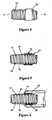
Figure 3 is a side view of the sleeve, in particular, showing hidden detail of the thread located on the inner surface of the sleeve -
Figure 4 is a side view of the sleeve when located about the end of a conduit, -
Figure 5 is a cross sectional view ofFigure 4 taken across lines X-X, and -
Figure 6 is a partial cross sectional of the conduit and connector, once a connector has been moulded about the sleeve and conduit. - The preferred embodiment of the present invention relates to a method of forming an end connector onto a delivery conduit that may be used in medical apparatus or ventilation therapy systems. The connector allows for the delivery conduit to be connected to other apparatus in the ventilation system, such as, an air generator, humidifier or mask. In particular, the delivery conduit must be capable of providing air, usually humidified, to the patient at a particular pressure, in order for ventilation therapy to be successful.
- A typical patient ventilation therapy system that uses such a flexible delivery conduit is shown in
Figure 1 . Here, a humidified positive pressure ventilation system is shown in which a patient 1 is receiving humidified and pressurised gases through apatient interface 2 connected to a humidified gases transportation pathway or delivery conduit 3. Delivery conduit 3 is connected to the outlet 4 of ahumidification chamber 5, which contains a volume ofwater 6. Delivery conduit 3 usually contains heating means or heater wires (not shown), which heat the walls of the conduit to reduce condensation of humidified gases within the conduit.Humidification chamber 6 is preferably formed from a plastics material and may have a highly heat conductive base (for example an aluminium base) which is in direct contact with aheater plate 7 ofhumidifier 8.Humidifier 8 is provided with control means or electronic controller 9 which may comprise a microprocessor based controller executing computer software commands stored in associated memory - Controller 9 receives input from sources such as user input means or
dial 10 through which a user of the device may, for example, set a predetermined required value (preset value) of humidity or temperature of the gases supplied to patient 1. The controller may also receive input from other sources, for example temperature and/orflow velocity sensors connector 13 and heaterplate temperature sensor 14. In response to the user set humidity or temperature value input viadial 10 and the other inputs, controller 9 determines when (or to what level) to energiseheater plate 7 to heat thewater 6 withinhumidification chamber 5. As the volume ofwater 6 withinhumidification chamber 5 is heated, water vapour begins to fill the volume of the chamber above the water's surface and is passed out of thehumidification chamber 5 outlet 4 with the flow of gases (for example air) provided from a gases supply means orblower 15 which enters the chamber throughinlet 16, Exhaled gases from the patient's mouth are passed directly to ambient surroundings. - Blower 15 is provided with variable pressure regulating means or
variable speed fan 21, which draws air or other gases throughblower inlet 17. The speed ofvariable speed fan 21 is controlled by electronic controller 18 (or alternatively the function ofcontroller 18 could be carried out by controller 9) in response to inputs from controller 9 and a user set predetermined required value (preset value) of pressure or fan speed viadial 19. - Referring now to
Figures 2 and 3 , asleeve 22 having aninternal surface 23 that is adapted for receiving a flexible conduit (indicated as 3 inFigure 1 ) is shown. The conduit is preferably a double-walled helically wound flexible conduit or tube as disclosed inUS Patent No. 5848223 , but may be of other appropriate conduit construction. Theinternal surface 23 of thesleeve 22 has athread 24 formed in it when moulded. Thethread 24 is a complimentary size and shape to that of the outer surface of the conduit 3. - The
sleeve 22 is preferably moulded from a thermoplastic material similar to the material the connector is manufactured or moulded from, but it is appreciated that other similar plastics materials may be used to construct the sleeve. Thesleeve thread 24 is a helical thread having twodifferent pitches thread 24 is shown inFigure 3 as hidden detail. Thestart 25 of thethread 24 begins at the bottom of thesleeve 22 and ends 26 approximately two thirds up the height of the sleeve. Thethread 24 consists of one and three-quarter rotations and has an incliningpitch 27 for one and a half rotations. Thelast quarter rotation 28 of the thread has no incline or decline. The ends of thethread 24 are also formed so as to taper into the inner surface of thesleeve 22; this makes it easier for a user to thread the sleeve onto the conduit. - Reference is now made to
Figures 4 and 5 , which illustrate thesleeve 22 in use and located about aflexible conduit 29. The conduit in this embodiment has anouter wall 30 and aninner wall 31 with electrical conductors (not shown) being disposed around theinner wall 31 with asupport bead 32 surrounding the conductors and maintaining adhesion of the conductors to the inner wall. Thesupport bead 32 has been heat bonded to the outside of the inner wall, this inner wall being a thin-walled tubular body. The outer wall is a ribbon applied over the wraps of the support bead spanning from one wrap to the next so as to define an outer wall for the conduit. The outer surface of thethread 24 abuts theouter wall 30 and, in the preferred form, causes a slight compression of the outer wall. As thethread 24 is slightly smaller in dimension than that of theouter wall 30 of theconduit 29, this causes there to be at tight fitting of thesleeve 22 about theconduit 29. - To obtain a conduit with a connector at one end, so that the conduit may be connected to other apparatus, such as a humidifier or blower, and to allow for gases to access and flow through said conduit, the
sleeve 22 is threaded onto one end of theconduit 29. A connector is then moulded over the conduit and sleeve as shown inFigure 6 . During the over moulding process molten thermoplastic material is injected into the cavity between thesleeve 22 and theconduit 29, resulting in a seal being made between thesleeve 22 andconduit 29, so that aconnector 33 is formed over the end of theconduit 29. As can be seen inFigure 6 , thesleeve 22 becomes part of the inner surface of theconnector 33 as it blends with theconnector 33 during moulding. Furthermore, thesleeve 22 acts as a means to determine where to locate theconnector 33 on the end of theconduit 29. - Although not shown in the Figures, the
sleeve 22 may not be fully enclosed within theconnector 33, but may extend slightly out of theend 34 of theconnector 33. In this form thesleeve 22 provides enhanced effect in reducing the occurrence of plastics flashings across the conduit walls. - The moulding of the
connector 33 over thesleeve 22 andconduit 29 results in a seal between theconduit 29 and theconnector 33 that prevents leakages in the conduit. Thesleeve 22 acts to isolate theouter film layer 30 of theconduit 29 during over moulding. Furthermore, the threads spiral protrusions act as a stop to prevent molten plastic from flowing between the inner andouter walls connector 33 to theconduit 29 also prevents moisture from moving between the inner andouter walls - The sleeve also acts as an insulator and prevents hot molten plastic from being in contact with the conduit during over moulding, preventing damage to the conduit
- The method of forming a connector on the end of a flexible conduit of the present invention has the advantage that it prevents the connector from loosening or breaking when the conduit is bent, pulled or stressed, which can occur in some cases where the connector is attached to the conduit using a bond, such as glue.
- Furthermore, the occurrences of flashing of plastic across the conduit walls will be prevented during moulding, ensuring that no air or water leakages occur within the conduit walls.
- Finally, the pitch of the thread on the sleeve is less than that provided by the outer wall and bead on the conduit, providing ease of assembly.
Claims (3)
- A method of forming a connector (33) on the end of a flexible conduit (29), using a sleeve (22) to protect said conduit (29), said sleeve (22) comprising a section of hollow cylinder having a thread (24) on its interior surface, said thread (24) being of corresponding size and shape to the outer surface of said conduit (29) so that said sleeve (22) can be threaded onto said end of said flexible conduit (29),
wherein said method comprises the steps of:a) threading said sleeve (22) onto said end of said flexible conduit (29), andb) moulding said connector (33) over said conduit (29) and said sleeve (22), said moulding causing said sleeve (22) to become an integral part of the inner surface of said connector (33). - A method of forming a connector (33) on the end of a flexible conduit (29) according to claim 1 wherein said conduit (29) is a helically wound tube having an outer wall (30), an inner wall (31), and which includes at least one electrical conductor wrapped around said inner wall (31), said at least one electrical conductor being covered with a bead.
- A method of forming a connector (33) on the end of a flexible conduit (29) according to claim 1 or 2 wherein said connector (33) is moulded over said conduit (29) and said sleeve (22) in such a manner that the edge of said sleeve (22) is not aligned with the edge of said connector (33) so that a part of said sleeve (22) extends from said overmoulded connector (33).
Applications Claiming Priority (2)
| Application Number | Priority Date | Filing Date | Title |
|---|---|---|---|
| NZ51615301 | 2001-12-14 | ||
| NZ51615301 | 2001-12-14 |
Publications (2)
| Publication Number | Publication Date |
|---|---|
| EP1319880A1 EP1319880A1 (en) | 2003-06-18 |
| EP1319880B1 true EP1319880B1 (en) | 2008-06-11 |
Family
ID=19928864
Family Applications (1)
| Application Number | Title | Priority Date | Filing Date |
|---|---|---|---|
| EP02027857A Expired - Lifetime EP1319880B1 (en) | 2001-12-14 | 2002-12-12 | Method of forming a connector on the end of a respiratory conduit |
Country Status (6)
| Country | Link |
|---|---|
| US (1) | US7157035B2 (en) |
| EP (1) | EP1319880B1 (en) |
| AT (1) | ATE398259T1 (en) |
| AU (1) | AU2002320660B2 (en) |
| DE (1) | DE60227037D1 (en) |
| ES (1) | ES2307705T3 (en) |
Cited By (1)
| Publication number | Priority date | Publication date | Assignee | Title |
|---|---|---|---|---|
| WO2023219557A1 (en) * | 2022-05-12 | 2023-11-16 | Hill-Rom Services Pte. Ltd. | Hose having a magnetic connector |
Families Citing this family (30)
| Publication number | Priority date | Publication date | Assignee | Title |
|---|---|---|---|---|
| US20040239001A1 (en) * | 2001-12-14 | 2004-12-02 | Edirisuriya Deshitha Airawana | Method of forming a respiratory conduit |
| NZ597020A (en) | 2005-08-15 | 2013-06-28 | Resmed Ltd | CPAP device with muffler downstream of flow generator capable of storing spill-back from a humidifier |
| US8544465B2 (en) | 2005-08-15 | 2013-10-01 | Redmed Limited | Compliant coupling or adaptor |
| US7677246B2 (en) * | 2005-09-23 | 2010-03-16 | Ric Investments, Llc | Modular pressure support system |
| GB2557116B (en) | 2011-06-03 | 2018-10-03 | Fisher & Paykel Healthcare Ltd | Medical tubes and methods of manufacture |
| CA3176668A1 (en) | 2012-03-15 | 2013-09-19 | Fisher & Paykel Healthcare Limited | Respiratory gas humidification system |
| US9974921B2 (en) | 2012-04-27 | 2018-05-22 | Fisher & Paykel Healthcare Limited | Usability features for respiratory humidification system |
| US10589050B2 (en) | 2012-11-14 | 2020-03-17 | Fisher & Paykel Healthcare Limited | Zone heating for respiratory circuits |
| EP3708212B1 (en) | 2012-12-04 | 2024-05-22 | Fisher & Paykel Healthcare Limited | A respiratory conduit |
| US10549060B2 (en) | 2013-06-25 | 2020-02-04 | ResMed Pty Ltd | Outlet connection assembly and method of making the same |
| CN108187208B (en) * | 2013-06-25 | 2022-03-01 | 瑞思迈私人有限公司 | Air outlet connecting assembly and manufacturing method thereof |
| WO2015038014A1 (en) | 2013-09-13 | 2015-03-19 | Fisher And Paykel Healthcare Limited | Humidification system |
| GB2534496B (en) | 2013-09-13 | 2020-04-01 | Fisher & Paykel Healthcare Ltd | A cartridge for a respiratory humidifier |
| WO2015060731A1 (en) | 2013-10-24 | 2015-04-30 | Fisher & Paykel Healthcare Limited | Delivery of respiratory gases |
| TWI663995B (en) | 2013-12-17 | 2019-07-01 | 澳大利亞商瑞思邁私人股份有限公司 | A respiratory pressure treatment system |
| CN110947069A (en) | 2013-12-20 | 2020-04-03 | 费雪派克医疗保健有限公司 | Humidification system connection |
| WO2015119515A1 (en) | 2014-02-07 | 2015-08-13 | Fisher & Paykel Healthcare Limited | Respiratory humidification system |
| US10751498B2 (en) | 2014-03-17 | 2020-08-25 | Fisher & Paykel Healthcare Limited | Medical tubes for respiratory systems |
| US11173272B2 (en) | 2014-05-02 | 2021-11-16 | Fisher & Paykel Healthcare Limited | Gas humidification arrangement |
| AU2015259944B2 (en) | 2014-05-13 | 2020-07-02 | Fisher & Paykel Healthcare Limited | Usability features for respiratory humidification system |
| CN112370630A (en) | 2014-06-03 | 2021-02-19 | 费雪派克医疗保健有限公司 | Flow mixer for respiratory therapy system |
| US11278689B2 (en) | 2014-11-17 | 2022-03-22 | Fisher & Paykel Healthcare Limited | Humidification of respiratory gases |
| EP3319675B1 (en) | 2015-07-07 | 2020-11-04 | ResMed Pty Ltd | Respiratory pressure therapy device |
| SG10202002134QA (en) | 2015-09-09 | 2020-05-28 | Fisher & Paykel Healthcare Ltd | Zone heating for respiratory circuits |
| PL3487571T3 (en) | 2016-07-21 | 2024-07-29 | Fisher & Paykel Healthcare Limited | Medical tubes for breathing circuit |
| WO2018106126A1 (en) | 2016-12-07 | 2018-06-14 | Fisher And Paykel Healthcare Limited | Sensing arrangements for medical devices |
| EP3544662B1 (en) | 2016-12-22 | 2024-11-27 | Fisher & Paykel Healthcare Limited | Medical tubes and methods of manufacture |
| EP3727547A1 (en) * | 2017-12-19 | 2020-10-28 | Koninklijke Philips N.V. | Ventilation system with cold passover humidification control |
| JP7661041B2 (en) | 2018-01-24 | 2025-04-14 | フィッシャー アンド ペイケル ヘルスケア リミテッド | Medical tubing for breathing circuits |
| EP3897798B1 (en) | 2018-12-18 | 2024-06-19 | ResMed Pty Ltd | Humidifier reservoir |
Family Cites Families (19)
| Publication number | Priority date | Publication date | Assignee | Title |
|---|---|---|---|---|
| FR717210A (en) | 1931-05-18 | 1932-01-05 | A Nortier Ets | Improvements to flexible gas hoses |
| US2561351A (en) * | 1944-10-05 | 1951-07-24 | Chicago Metal Hose Corp | Coupling structure |
| US3287485A (en) * | 1963-03-21 | 1966-11-22 | Us Rubber Co | Method of providing a fluid tight seal between two rigid components |
| US3963856A (en) * | 1974-11-25 | 1976-06-15 | Steward Plastics, Inc. | Flexible, corrugated, plastic tubing having conductive helical bead |
| US4235832A (en) * | 1978-07-31 | 1980-11-25 | Alden Research Foundation | Molding method |
| US4292267A (en) * | 1978-11-02 | 1981-09-29 | Acco Industries Inc. | Method for terminating flexible helical wire conduit |
| US4348348A (en) * | 1980-06-23 | 1982-09-07 | Teleflex Incorporated | Method for making a remote control assembly with vibration dampener |
| US4462648A (en) * | 1981-03-19 | 1984-07-31 | Repa Feinstanzwerk Gmbh | Apparatus for providing a reliable electrical connection |
| US4490575A (en) * | 1983-05-26 | 1984-12-25 | Automation Industries, Inc. | Flexible hose with external sheathed electrical conductor |
| US5302336A (en) * | 1987-04-16 | 1994-04-12 | Metzeler Automotive Profiles Gmbh | Method for producing molded hose branches from rubber and a hose produced by the method |
| NO172416C (en) * | 1991-02-11 | 1993-07-14 | Alcatel Stk As | PROCEDURE AND CONNECTOR FOR CONNECTING TWO ELECTRICAL CONDUCTORS WITH INSULATION CAPS |
| JP2605216B2 (en) * | 1994-02-07 | 1997-04-30 | 東亜高級継手バルブ製造株式会社 | Threaded pipe fittings |
| FR2717556B1 (en) | 1994-03-16 | 1996-04-26 | Gloanec | Set consisting of a flexible tube and a coaxial tip. |
| US5848223A (en) * | 1994-05-27 | 1998-12-08 | Steward Plastics, Inc. | Double-walled flexible tubing product with helical support bead and heating conductor and apparatus and method for making |
| US6219490B1 (en) * | 1996-06-13 | 2001-04-17 | Mallinckrodt Inc. | Ventilation tube, particularly for medical devices |
| US6123111A (en) * | 1996-09-24 | 2000-09-26 | Alfred Karcher Gmbh & Co. | High pressure hose having a fitting for attachment to a corresponding connector member |
| DE19800986B4 (en) | 1998-01-14 | 2007-01-25 | Franz Schuck | Pipe connection, in particular for a house introduction combination, with a corrugated pipe section |
| US6726678B1 (en) * | 2001-02-22 | 2004-04-27 | Isurgical, Llc | Implantable reservoir and system for delivery of a therapeutic agent |
| JP4263975B2 (en) * | 2003-09-19 | 2009-05-13 | 積水化学工業株式会社 | Water faucet joint with fusion saddle |
-
2002
- 2002-12-09 US US10/314,812 patent/US7157035B2/en not_active Expired - Lifetime
- 2002-12-10 AU AU2002320660A patent/AU2002320660B2/en not_active Expired
- 2002-12-12 ES ES02027857T patent/ES2307705T3/en not_active Expired - Lifetime
- 2002-12-12 DE DE60227037T patent/DE60227037D1/en not_active Expired - Lifetime
- 2002-12-12 AT AT02027857T patent/ATE398259T1/en not_active IP Right Cessation
- 2002-12-12 EP EP02027857A patent/EP1319880B1/en not_active Expired - Lifetime
Cited By (1)
| Publication number | Priority date | Publication date | Assignee | Title |
|---|---|---|---|---|
| WO2023219557A1 (en) * | 2022-05-12 | 2023-11-16 | Hill-Rom Services Pte. Ltd. | Hose having a magnetic connector |
Also Published As
| Publication number | Publication date |
|---|---|
| DE60227037D1 (en) | 2008-07-24 |
| US7157035B2 (en) | 2007-01-02 |
| ATE398259T1 (en) | 2008-07-15 |
| ES2307705T3 (en) | 2008-12-01 |
| US20030111249A1 (en) | 2003-06-19 |
| EP1319880A1 (en) | 2003-06-18 |
| AU2002320660B2 (en) | 2008-03-06 |
Similar Documents
| Publication | Publication Date | Title |
|---|---|---|
| US7157035B2 (en) | Method of forming a respiratory conduit | |
| US20040239001A1 (en) | Method of forming a respiratory conduit | |
| AU718139B2 (en) | Heated respiratory conduit | |
| US20250135146A1 (en) | Breathing tube | |
| US20240399097A1 (en) | Components for medical circuits | |
| US7588029B2 (en) | Humidified gases delivery apparatus | |
| EP1369141B1 (en) | Connector for the pneumatical and electrical coupling between a gases supply means and a gas conduit | |
| US11839719B2 (en) | Heated respiratory hose wiring | |
| US11813403B2 (en) | Heated respiratory hose wiring | |
| US8303173B2 (en) | Dual potting temperature probe | |
| AU2013232848B2 (en) | Respiratory gas humidification system | |
| WO2004108218A1 (en) | A probe and breathing circuit | |
| AU727989B2 (en) | Heated respiratory conduit | |
| AU2004201521B2 (en) | A Method of Forming A Respiratory Conduit | |
| EP1295621B1 (en) | Humidified gases delivery apparatus | |
| EP3794263B1 (en) | Heated respiratory hose wirings | |
| US20240115847A1 (en) | Heated respiratory hose support helix incorporating lumens | |
| HK1051656B (en) | Humidified gases delivery apparatus | |
| HK1051656A (en) | Humidified gases delivery apparatus |
Legal Events
| Date | Code | Title | Description |
|---|---|---|---|
| PUAI | Public reference made under article 153(3) epc to a published international application that has entered the european phase |
Free format text: ORIGINAL CODE: 0009012 |
|
| AK | Designated contracting states |
Designated state(s): AT BE BG CH CY CZ DE DK EE ES FI FR GB GR IE IT LI LU MC NL PT SE SI SK TR |
|
| AX | Request for extension of the european patent |
Extension state: AL LT LV MK RO |
|
| 17P | Request for examination filed |
Effective date: 20030731 |
|
| AKX | Designation fees paid |
Designated state(s): AT BE BG CH CY CZ DE DK EE ES FI FR GB GR IE IT LI LU MC NL PT SE SI SK TR |
|
| 17Q | First examination report despatched |
Effective date: 20040216 |
|
| RIC1 | Information provided on ipc code assigned before grant |
Ipc: A61M 16/08 20060101ALI20070731BHEP Ipc: F16L 33/24 20060101AFI20070731BHEP Ipc: F16L 25/00 20060101ALI20070731BHEP |
|
| RTI1 | Title (correction) |
Free format text: METHOD OF FORMING A CONNECTOR ON THE END OF A RESPIRATORY CONDUIT |
|
| GRAP | Despatch of communication of intention to grant a patent |
Free format text: ORIGINAL CODE: EPIDOSNIGR1 |
|
| GRAS | Grant fee paid |
Free format text: ORIGINAL CODE: EPIDOSNIGR3 |
|
| GRAA | (expected) grant |
Free format text: ORIGINAL CODE: 0009210 |
|
| AK | Designated contracting states |
Kind code of ref document: B1 Designated state(s): AT BE BG CH CY CZ DE DK EE ES FI FR GB GR IE IT LI LU MC NL PT SE SI SK TR |
|
| REG | Reference to a national code |
Ref country code: GB Ref legal event code: FG4D |
|
| REG | Reference to a national code |
Ref country code: CH Ref legal event code: EP |
|
| REF | Corresponds to: |
Ref document number: 60227037 Country of ref document: DE Date of ref document: 20080724 Kind code of ref document: P |
|
| REG | Reference to a national code |
Ref country code: IE Ref legal event code: FG4D |
|
| PG25 | Lapsed in a contracting state [announced via postgrant information from national office to epo] |
Ref country code: SI Free format text: LAPSE BECAUSE OF FAILURE TO SUBMIT A TRANSLATION OF THE DESCRIPTION OR TO PAY THE FEE WITHIN THE PRESCRIBED TIME-LIMIT Effective date: 20080611 Ref country code: FI Free format text: LAPSE BECAUSE OF FAILURE TO SUBMIT A TRANSLATION OF THE DESCRIPTION OR TO PAY THE FEE WITHIN THE PRESCRIBED TIME-LIMIT Effective date: 20080611 |
|
| PG25 | Lapsed in a contracting state [announced via postgrant information from national office to epo] |
Ref country code: NL Free format text: LAPSE BECAUSE OF FAILURE TO SUBMIT A TRANSLATION OF THE DESCRIPTION OR TO PAY THE FEE WITHIN THE PRESCRIBED TIME-LIMIT Effective date: 20080611 Ref country code: AT Free format text: LAPSE BECAUSE OF FAILURE TO SUBMIT A TRANSLATION OF THE DESCRIPTION OR TO PAY THE FEE WITHIN THE PRESCRIBED TIME-LIMIT Effective date: 20080611 |
|
| NLV1 | Nl: lapsed or annulled due to failure to fulfill the requirements of art. 29p and 29m of the patents act | ||
| REG | Reference to a national code |
Ref country code: ES Ref legal event code: FG2A Ref document number: 2307705 Country of ref document: ES Kind code of ref document: T3 |
|
| PG25 | Lapsed in a contracting state [announced via postgrant information from national office to epo] |
Ref country code: PT Free format text: LAPSE BECAUSE OF FAILURE TO SUBMIT A TRANSLATION OF THE DESCRIPTION OR TO PAY THE FEE WITHIN THE PRESCRIBED TIME-LIMIT Effective date: 20081111 Ref country code: SE Free format text: LAPSE BECAUSE OF FAILURE TO SUBMIT A TRANSLATION OF THE DESCRIPTION OR TO PAY THE FEE WITHIN THE PRESCRIBED TIME-LIMIT Effective date: 20080911 Ref country code: CZ Free format text: LAPSE BECAUSE OF FAILURE TO SUBMIT A TRANSLATION OF THE DESCRIPTION OR TO PAY THE FEE WITHIN THE PRESCRIBED TIME-LIMIT Effective date: 20080611 |
|
| PG25 | Lapsed in a contracting state [announced via postgrant information from national office to epo] |
Ref country code: BE Free format text: LAPSE BECAUSE OF FAILURE TO SUBMIT A TRANSLATION OF THE DESCRIPTION OR TO PAY THE FEE WITHIN THE PRESCRIBED TIME-LIMIT Effective date: 20080611 Ref country code: SK Free format text: LAPSE BECAUSE OF FAILURE TO SUBMIT A TRANSLATION OF THE DESCRIPTION OR TO PAY THE FEE WITHIN THE PRESCRIBED TIME-LIMIT Effective date: 20080611 |
|
| PLBE | No opposition filed within time limit |
Free format text: ORIGINAL CODE: 0009261 |
|
| STAA | Information on the status of an ep patent application or granted ep patent |
Free format text: STATUS: NO OPPOSITION FILED WITHIN TIME LIMIT |
|
| PG25 | Lapsed in a contracting state [announced via postgrant information from national office to epo] |
Ref country code: DK Free format text: LAPSE BECAUSE OF FAILURE TO SUBMIT A TRANSLATION OF THE DESCRIPTION OR TO PAY THE FEE WITHIN THE PRESCRIBED TIME-LIMIT Effective date: 20080611 Ref country code: EE Free format text: LAPSE BECAUSE OF FAILURE TO SUBMIT A TRANSLATION OF THE DESCRIPTION OR TO PAY THE FEE WITHIN THE PRESCRIBED TIME-LIMIT Effective date: 20080611 Ref country code: BG Free format text: LAPSE BECAUSE OF FAILURE TO SUBMIT A TRANSLATION OF THE DESCRIPTION OR TO PAY THE FEE WITHIN THE PRESCRIBED TIME-LIMIT Effective date: 20080911 |
|
| 26N | No opposition filed |
Effective date: 20090312 |
|
| PG25 | Lapsed in a contracting state [announced via postgrant information from national office to epo] |
Ref country code: MC Free format text: LAPSE BECAUSE OF NON-PAYMENT OF DUE FEES Effective date: 20081231 |
|
| REG | Reference to a national code |
Ref country code: CH Ref legal event code: PL |
|
| PG25 | Lapsed in a contracting state [announced via postgrant information from national office to epo] |
Ref country code: LI Free format text: LAPSE BECAUSE OF NON-PAYMENT OF DUE FEES Effective date: 20081231 Ref country code: CH Free format text: LAPSE BECAUSE OF NON-PAYMENT OF DUE FEES Effective date: 20081231 Ref country code: IE Free format text: LAPSE BECAUSE OF NON-PAYMENT OF DUE FEES Effective date: 20081212 |
|
| PG25 | Lapsed in a contracting state [announced via postgrant information from national office to epo] |
Ref country code: CY Free format text: LAPSE BECAUSE OF FAILURE TO SUBMIT A TRANSLATION OF THE DESCRIPTION OR TO PAY THE FEE WITHIN THE PRESCRIBED TIME-LIMIT Effective date: 20080611 Ref country code: LU Free format text: LAPSE BECAUSE OF NON-PAYMENT OF DUE FEES Effective date: 20081212 |
|
| PG25 | Lapsed in a contracting state [announced via postgrant information from national office to epo] |
Ref country code: TR Free format text: LAPSE BECAUSE OF FAILURE TO SUBMIT A TRANSLATION OF THE DESCRIPTION OR TO PAY THE FEE WITHIN THE PRESCRIBED TIME-LIMIT Effective date: 20080611 |
|
| PG25 | Lapsed in a contracting state [announced via postgrant information from national office to epo] |
Ref country code: GR Free format text: LAPSE BECAUSE OF FAILURE TO SUBMIT A TRANSLATION OF THE DESCRIPTION OR TO PAY THE FEE WITHIN THE PRESCRIBED TIME-LIMIT Effective date: 20080912 |
|
| REG | Reference to a national code |
Ref country code: FR Ref legal event code: PLFP Year of fee payment: 14 |
|
| REG | Reference to a national code |
Ref country code: FR Ref legal event code: PLFP Year of fee payment: 15 |
|
| REG | Reference to a national code |
Ref country code: FR Ref legal event code: PLFP Year of fee payment: 16 |
|
| PGFP | Annual fee paid to national office [announced via postgrant information from national office to epo] |
Ref country code: DE Payment date: 20211117 Year of fee payment: 20 Ref country code: GB Payment date: 20211118 Year of fee payment: 20 Ref country code: FR Payment date: 20211118 Year of fee payment: 20 |
|
| PGFP | Annual fee paid to national office [announced via postgrant information from national office to epo] |
Ref country code: IT Payment date: 20211117 Year of fee payment: 20 |
|
| PGFP | Annual fee paid to national office [announced via postgrant information from national office to epo] |
Ref country code: ES Payment date: 20220103 Year of fee payment: 20 |
|
| REG | Reference to a national code |
Ref country code: DE Ref legal event code: R071 Ref document number: 60227037 Country of ref document: DE |
|
| REG | Reference to a national code |
Ref country code: GB Ref legal event code: PE20 Expiry date: 20221211 |
|
| PG25 | Lapsed in a contracting state [announced via postgrant information from national office to epo] |
Ref country code: GB Free format text: LAPSE BECAUSE OF EXPIRATION OF PROTECTION Effective date: 20221211 |
|
| REG | Reference to a national code |
Ref country code: ES Ref legal event code: FD2A Effective date: 20230427 |
|
| PG25 | Lapsed in a contracting state [announced via postgrant information from national office to epo] |
Ref country code: ES Free format text: LAPSE BECAUSE OF EXPIRATION OF PROTECTION Effective date: 20221213 |