EP1319832A2 - Electromagnetically operated pump - Google Patents
Electromagnetically operated pump Download PDFInfo
- Publication number
- EP1319832A2 EP1319832A2 EP02102744A EP02102744A EP1319832A2 EP 1319832 A2 EP1319832 A2 EP 1319832A2 EP 02102744 A EP02102744 A EP 02102744A EP 02102744 A EP02102744 A EP 02102744A EP 1319832 A2 EP1319832 A2 EP 1319832A2
- Authority
- EP
- European Patent Office
- Prior art keywords
- cylinder
- pump
- piston element
- coil
- base
- Prior art date
- Legal status (The legal status is an assumption and is not a legal conclusion. Google has not performed a legal analysis and makes no representation as to the accuracy of the status listed.)
- Granted
Links
Images


Classifications
-
- F—MECHANICAL ENGINEERING; LIGHTING; HEATING; WEAPONS; BLASTING
- F04—POSITIVE - DISPLACEMENT MACHINES FOR LIQUIDS; PUMPS FOR LIQUIDS OR ELASTIC FLUIDS
- F04B—POSITIVE-DISPLACEMENT MACHINES FOR LIQUIDS; PUMPS
- F04B17/00—Pumps characterised by combination with, or adaptation to, specific driving engines or motors
- F04B17/03—Pumps characterised by combination with, or adaptation to, specific driving engines or motors driven by electric motors
- F04B17/04—Pumps characterised by combination with, or adaptation to, specific driving engines or motors driven by electric motors using solenoids
- F04B17/046—Pumps characterised by combination with, or adaptation to, specific driving engines or motors driven by electric motors using solenoids the fluid flowing through the moving part of the motor
Definitions
- the present invention concerns an electromagnetically operated pump to feed two-stroke internal-combustion engines with precise and controlled amounts of oil.
- the present invention concerns a pump of this type, the structure of which - while preserving the characteristics of a simple construction, a metering precision and an easy setting, which are indispensable for the specific use for which the pump is designed - allows to considerably reduce its overall dimensions and guarantees an improved reliability thereof.
- the pump according to the invention - of the type comprising, in a casing: a cylinder; a piston element with a through pipe, axially movable in said cylinder, an electromagnetic coil coaxial to the cylinder, to control the movements of the piston element against the action of spring means; a pumping chamber for the oil to be fed, coaxial to the cylinder and close to a first base thereof; and valve means housed in said casing and in said chamber, one of said means cooperating with a first end of said piston element - is characterized in that, the electromagnetic coil is an annular coil which surrounds the piston element and acts frontwards onto a keeper of ferromagnetic material, close and parallel to the second base of the cylinder and connected to the second end of the piston element, said annular coil projecting from said second base of the cylinder.
- said piston element is of nonmagnetic material and said annular coil is housed into a cavity of the cylinder formed on the front of said keeper in said second base of the cylinder.
- a disk is interposed between said second base of the cylinder and said keeper, said disk having a central hole through which said piston element freely passes.
- the spring means act between said disk and said keeper, opposing the movements of the piston element controlled by said coil, said spring means being positioned close to the hole of said disk, or close to its periphery.
- the spring means are housed peripherally into the pumping chamber, so as to act directly on the piston element, in correspondence of its first end.
- Said spring means preferably consist of a cylindrical helicoidal spring, coaxial to the cylinder of said pump.
- the piston element is suitably formed - in the different variants of the aforedescribed embodiment - with a portion of reduced diameter towards its second end, the extension of said portion contributing to determine the capacity of the pump.
- the piston element has instead a constant diameter and the capacity of the pump depends on the distance between the keeper and the cylinder, when the keeper is subject merely to the action of the spring means which oppose the movements of the piston element controlled by said coil.
- spring means can consist of a Belleville washer, coaxial to the cylinder of the pump and interposed between said second base of the cylinder and said keeper, or of a cylindrical helicoidal spring housed peripherally into the pumping chamber.
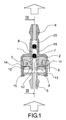
- Fig. 1 is an axial section view of a first embodiment of the pump according to the present invention
- Fig. 2 shows a detail of the pump of fig. 1, along the line II-II thereof;
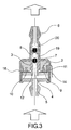
- Fig. 3 illustrates a first variant of the embodiment of the pump shown in fig. 1;
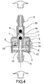
- Fig. 4 illustrates a second variant of the embodiment of the pump shown in fig. 1;
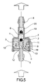
- Fig. 5 shows a second embodiment of the pump according to the present invention, illustrating a first variant thereof
- Fig. 6 illustrates a second variant of the embodiment of the pump shown in fig. 5;
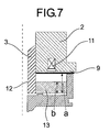
- Fig. 7 shows a detail of the pump of fig. 6, along the line VII-VII thereof.
- the pump according to the present invention is of the type comprising - as clearly illustrated - a casing 1 housing a cylinder 2 and a piston element 3, axially movable in the cylinder 2 and crossed by a through pipe 4 connected to pipe unions 5 and 6 in the casing 1, for the inlet and respectively the outlet of oil.
- a pumping chamber 8 Close to a first base 7 of the cylinder 2, in contact with the casing 1 and along the corresponding pipe union 6, there is a pumping chamber 8 to pump the oil to be fed, said chamber also housing valve means of the pump, as described hereinafter.
- a cavity 10 is formed close to the second base 9 of the cylinder 2, into said cavity there being housed a compact electromagnetic annular coil 11 which surrounds the piston element 3 and which is fed with pulse current in strict correlation with the running of the two-stroke engine to be equipped with the pump.
- the depth of the cavity 10 slightly exceeds the height of the coil 11, so that this latter can be fully housed therein and be efficiently protected.
- the piston element 3 is connected, at its end 12 in correspondence of the base 9 of the cylinder 2, to a keeper 13 parallel and close to said base 9.
- the electromagnetic coil 11 acts frontwards onto said keeper 13 - which is of ferromagnetic material - against the action of spring means.
- the keeper 13 draws in its movements the piston element 3, preferably made of nonmagnetic material. Thanks to the efficiency of the frontward action - with a low magnetic gap and a magnetic circuit with low reluctance - of the electromagnetic coil 11 on the keeper 13, the movements of the piston element 3 of the pump according to the invention can be controlled by means of a coil 11 of very small dimensions and having a very compact structure.
- the efficiency of said action is in fact far higher than that which could be obtained up to date in the pumps having coils usually extending along the whole cylinder of the pump, externally thereof, and acting directly onto a piston of ferromagnetic material in an axial sense, in magnetic circuits with a very high reluctance.
- the arrangement of the present invention thus allows to considerably reduce the overall dimensions of the pump, providing an advantage which is particularly important for the applications pointed out in the introductory part of the present description, such as feeding oil in two-stroke internal combustion engines.
- a disk 14 is interposed between the second base 9 of the cylinder 2 and the keeper 13, said disk 14 preferably being of nonmagnetic material and having a central hole through which freely passes the end 12 of said piston element 3 having a portion 12A of reduced diameter (fig. 2); the portion of wider diameter of said piston element 3 stops instead against said disk 14.
- Spring means act between said disk 14 and said keeper 13 opposing the movements of the piston element 3 controlled by the coil 11.
- said spring means are centrally positioned - in 15 - close to the hole of the disk 14; whereas, in the variant of fig. 3, they are positioned - in 16 - close to the periphery of the disk 14.
- said spring means consist of a cylindrical helicoidal spring 17, coaxial to the cylinder 2 and housed peripherally into the pumping chamber 8.
- the spring 17 acts directly onto the piston element 3, in correspondence of its first end, opposite to that fixed to the keeper 13.
- the piston element 3 has a constant diameter, it being obtained from a ground bar (thereby reducing the costs in respect of the previous embodiment).
- the coil 11 controls, when energized, the movements of the piston element 3 towards the chamber 8, while attracting the keeper 13 against the action of the spring means 15, 16 or 17.
- Such means produce movements in the opposite sense when the coil 11 is deenergized.
- Two ball valves 19 and 20 are provided, in known manner, in the pipe union 6 in the casing 1, in correspondence of the oil pumping chamber 8, the valve 19 cooperating with the end of the piston element 3 in correspondence of the base 7 of the cylinder 2.
- the valve 19 is closed while the valve 20 opens.
- the valve 20 closes while the valve 19 opens again.
- Fig. 2 shows a detail of fig. 1, illustrating how the capacity of the oil being pumped, for each stroke of the pump according to the invention, may be determined by varying the distance a-b in fig. 1, namely the ratio between the length of the portion of wider diameter and the length of the portion 12A of reduced diameter of the piston element 3. This obviously also applies to the other variants of the pump adopting a similar piston element 3 (figs. 3 and 4).
- the capacity of the oil being pumped for each stroke of the pump is instead determined, as clearly shown in fig. 7, by the distance a-b between the keeper 13 and the base 9 of the cylinder 2, when said keeper is subject merely to the action of the spring means 18 or 17 and the coil 11 is deenergized.
- the aforedescribed pump has a very simple structure and a highly reliable working but, above all - as already mentioned - it allows to drastically limit the dimensions of the electric circuit and of the coil controlling the movements of the piston element; this considerably affects the overall dimensions of the pump, so as to be able to assert that it leads to a miniaturization thereof.
- the pump according to the invention can moreover be easily adapted, with reduced costs, to the most different requirements of capacity, by simply varying the axial position of the abutment of the piston element 3, formed in two portions of different diameter.
Landscapes
- Engineering & Computer Science (AREA)
- Physics & Mathematics (AREA)
- Fluid Mechanics (AREA)
- Mechanical Engineering (AREA)
- General Engineering & Computer Science (AREA)
- Electromagnetic Pumps, Or The Like (AREA)
- Lubrication Of Internal Combustion Engines (AREA)
- Surgical Instruments (AREA)
- External Artificial Organs (AREA)
Abstract
Description
Claims (13)
- Electromagnetically operated pump to feed two-stroke internal-combustion engines with precise and controlled amounts of oil - of the type comprising, in a casing (1): a cylinder (2); a piston element (3) with a through pipe (4), axially movable in said cylinder (2); an electromagnetic coil (11) coaxial to the cylinder (2), to control the movements of the piston element (3) against the action of spring means (15, 16, 17, 18); a pumping chamber (8) for the oil to be fed, coaxial to the cylinder (2) and close to a first base (7) thereof; and valve means (19, 20) housed in said casing (1) and in said chamber (8), one of said means (19) cooperating with a first end of said piston element (3) - characterized in that, the electromagnetic coil (11) is an annular coil which surrounds the piston element (3) and acts frontwards onto a keeper (13) of ferromagnetic material, close and parallel to the second base (9) of the cylinder (2) and connected to the second end (12) of the piston element (3), said annular coil (11) projecting from said second base (9) of the cylinder (2).
- Pump as in claim 1), wherein the piston element (3) is of nonmagnetic material.
- Pump as in claim 1), wherein said annular coil (11) is housed into a cavity (10) of the cylinder (2) formed on the front of said keeper (13) in said second base (9) of the cylinder (2).
- Pump as in claim 3), wherein said cavity (10) of the cylinder (2) housing the coil (11) has a depth which slightly exceeds the height of said coil (11).
- Pump as in claim 1), wherein a disk (14) is interposed between said second base (9) of the cylinder (2) and said keeper (13), said disk (14) having a central hole through which said piston element (3) freely passes, between said disk (14) and said keeper (13) acting the spring means (15, 16) which oppose the movements of the piston element (3) controlled by said coil (11).
- Pump as in claim 5), wherein said spring means (15) are positioned close to the hole of said disk (14).
- Pump as in claim 5), wherein said spring means (16) are positioned close to the periphery of the disk (14).
- Pump as in claims 5) to 7), wherein the spring means (17) consist of a cylindrical helicoidal spring, coaxial to the cylinder (2) of the pump.
- Pump as in claims 5) to 8), wherein said disk (14) is of nonmagnetic material.
- Pump as in claims 1) to 9), wherein the piston element (3) is formed with a portion of wider diameter and a portion of reduced diameter (12A) towards its second end (12).
- Pump as in claims 1) to 4), wherein the piston element (3) has a constant diameter.
- Pump as in claim 1), wherein a Belleville washer (18) is interposed between said second base (9) of the cylinder (2) and said keeper (13), coaxial to the cylinder (2) of the pump, said washer (18) forming the spring means which oppose the movements of the piston element (3) controlled by said coil (11).
- Pump as in claim 1), wherein the spring means which oppose the movements of the piston element (3) controlled by said coil (11) consist of a cylindrical helicoidal spring (17), housed peripherally into the pumping chamber (8) and acting directly on the piston element (3), in correspondence of its first end.
Applications Claiming Priority (2)
| Application Number | Priority Date | Filing Date | Title |
|---|---|---|---|
| IT2001MI002647A ITMI20012647A1 (en) | 2001-12-13 | 2001-12-13 | PUMP CONTROLLED BY ELECTROMAGNET |
| ITMI20012647 | 2001-12-13 |
Publications (3)
| Publication Number | Publication Date |
|---|---|
| EP1319832A2 true EP1319832A2 (en) | 2003-06-18 |
| EP1319832A3 EP1319832A3 (en) | 2004-01-21 |
| EP1319832B1 EP1319832B1 (en) | 2008-04-09 |
Family
ID=11448694
Family Applications (1)
| Application Number | Title | Priority Date | Filing Date |
|---|---|---|---|
| EP02102744A Expired - Lifetime EP1319832B1 (en) | 2001-12-13 | 2002-12-12 | Electromagnetically operated pump |
Country Status (4)
| Country | Link |
|---|---|
| EP (1) | EP1319832B1 (en) |
| AT (1) | ATE391837T1 (en) |
| DE (1) | DE60225996D1 (en) |
| IT (1) | ITMI20012647A1 (en) |
Cited By (1)
| Publication number | Priority date | Publication date | Assignee | Title |
|---|---|---|---|---|
| EP1607629A1 (en) * | 2004-06-11 | 2005-12-21 | Olab S.r.l. | Vibration pump |
Family Cites Families (5)
| Publication number | Priority date | Publication date | Assignee | Title |
|---|---|---|---|---|
| GB1102555A (en) * | 1964-03-14 | 1968-02-07 | Eberspaecher Walter | Electromagnetically-actuated reciprocating piston pumps for liquids |
| US3479959A (en) * | 1967-10-23 | 1969-11-25 | William N Christensen | Electromagnetic metering pump |
| DE3735019A1 (en) * | 1986-10-14 | 1988-05-19 | Orbital Eng Pty | LUBRICATION SYSTEM FOR A COMBUSTION ENGINE AND PUMP HERE |
| FR2641338A1 (en) * | 1988-12-30 | 1990-07-06 | Peugeot Motocycles | LOW FLOW PUMP, PARTICULARLY FOR LUBRICATING A TWO-STROKE ENGINE |
| IT1299987B1 (en) * | 1998-04-27 | 2000-04-04 | Magneti Marelli Spa | VOLUMETRIC PUMP. |
-
2001
- 2001-12-13 IT IT2001MI002647A patent/ITMI20012647A1/en unknown
-
2002
- 2002-12-12 AT AT02102744T patent/ATE391837T1/en not_active IP Right Cessation
- 2002-12-12 DE DE60225996T patent/DE60225996D1/en not_active Expired - Lifetime
- 2002-12-12 EP EP02102744A patent/EP1319832B1/en not_active Expired - Lifetime
Cited By (1)
| Publication number | Priority date | Publication date | Assignee | Title |
|---|---|---|---|---|
| EP1607629A1 (en) * | 2004-06-11 | 2005-12-21 | Olab S.r.l. | Vibration pump |
Also Published As
| Publication number | Publication date |
|---|---|
| ITMI20012647A1 (en) | 2003-06-13 |
| EP1319832B1 (en) | 2008-04-09 |
| DE60225996D1 (en) | 2008-05-21 |
| ATE391837T1 (en) | 2008-04-15 |
| EP1319832A3 (en) | 2004-01-21 |
Similar Documents
| Publication | Publication Date | Title |
|---|---|---|
| US4946107A (en) | Electromagnetic fuel injection valve | |
| JP5886830B2 (en) | High pressure pump | |
| JP5537498B2 (en) | High pressure fuel supply pump with electromagnetic suction valve | |
| JP3142038B2 (en) | solenoid valve | |
| US20100206252A1 (en) | High-pressure pump for a fuel system of an internal combustion engine | |
| KR102178299B1 (en) | Fuel pump and inlet valve assembly thereof | |
| US4015912A (en) | Electromagnetic pumping device for liquids | |
| JP5905046B2 (en) | High pressure fuel supply pump with electromagnetic suction valve | |
| US4573659A (en) | Fluid control valve | |
| JP2000145623A (en) | Electromagnetic pump | |
| CN105190016B (en) | High-pressure fuel feed pump | |
| EP1319832B1 (en) | Electromagnetically operated pump | |
| CN106030093A (en) | Electromagnetically actuated valve | |
| US4352645A (en) | Solenoid pump adapted for noiseless operation | |
| JP5502806B2 (en) | Solenoid valve and high-pressure pump using the same | |
| CN108368810B (en) | Solenoid-operable inlet valve and high-pressure pump with the same | |
| US20180230955A1 (en) | Electromagnetic Switching Valve and High-Pressure Fuel Pump | |
| JP2002048031A (en) | Fuel injection device | |
| US20150104338A1 (en) | Electromagnetic Pump | |
| JP5720637B2 (en) | Linear solenoid | |
| EP1236894B1 (en) | Electromagnetically operated pump | |
| US2533164A (en) | Electromagnetic pump | |
| EP1236895B1 (en) | Electromagnetically operated pump | |
| US1664607A (en) | Fuel-injection system | |
| JP6417971B2 (en) | Suction metering valve |
Legal Events
| Date | Code | Title | Description |
|---|---|---|---|
| PUAI | Public reference made under article 153(3) epc to a published international application that has entered the european phase |
Free format text: ORIGINAL CODE: 0009012 |
|
| AK | Designated contracting states |
Designated state(s): AT BE BG CH CY CZ DE DK EE ES FI FR GB GR IE IT LI LU MC NL PT SE SI SK TR |
|
| AX | Request for extension of the european patent |
Extension state: AL LT LV MK RO |
|
| PUAL | Search report despatched |
Free format text: ORIGINAL CODE: 0009013 |
|
| AK | Designated contracting states |
Kind code of ref document: A3 Designated state(s): AT BE BG CH CY CZ DE DK EE ES FI FR GB GR IE IT LI LU MC NL PT SE SI SK TR |
|
| AX | Request for extension of the european patent |
Extension state: AL LT LV MK RO |
|
| RIC1 | Information provided on ipc code assigned before grant |
Ipc: 7F 01M 1/02 A Ipc: 7F 04B 17/04 B |
|
| 17P | Request for examination filed |
Effective date: 20040719 |
|
| AKX | Designation fees paid |
Designated state(s): AT BE BG CH CY CZ DE DK EE ES FI FR GB GR IE IT LI LU MC NL PT SE SI SK TR |
|
| 17Q | First examination report despatched |
Effective date: 20070622 |
|
| GRAP | Despatch of communication of intention to grant a patent |
Free format text: ORIGINAL CODE: EPIDOSNIGR1 |
|
| GRAS | Grant fee paid |
Free format text: ORIGINAL CODE: EPIDOSNIGR3 |
|
| GRAA | (expected) grant |
Free format text: ORIGINAL CODE: 0009210 |
|
| AK | Designated contracting states |
Kind code of ref document: B1 Designated state(s): AT BE BG CH CY CZ DE DK EE ES FI FR GB GR IE IT LI LU MC NL PT SE SI SK TR |
|
| REG | Reference to a national code |
Ref country code: GB Ref legal event code: FG4D |
|
| REG | Reference to a national code |
Ref country code: CH Ref legal event code: EP |
|
| REG | Reference to a national code |
Ref country code: IE Ref legal event code: FG4D |
|
| REF | Corresponds to: |
Ref document number: 60225996 Country of ref document: DE Date of ref document: 20080521 Kind code of ref document: P |
|
| PG25 | Lapsed in a contracting state [announced via postgrant information from national office to epo] |
Ref country code: SI Free format text: LAPSE BECAUSE OF FAILURE TO SUBMIT A TRANSLATION OF THE DESCRIPTION OR TO PAY THE FEE WITHIN THE PRESCRIBED TIME-LIMIT Effective date: 20080409 |
|
| NLV1 | Nl: lapsed or annulled due to failure to fulfill the requirements of art. 29p and 29m of the patents act | ||
| PG25 | Lapsed in a contracting state [announced via postgrant information from national office to epo] |
Ref country code: NL Free format text: LAPSE BECAUSE OF FAILURE TO SUBMIT A TRANSLATION OF THE DESCRIPTION OR TO PAY THE FEE WITHIN THE PRESCRIBED TIME-LIMIT Effective date: 20080409 Ref country code: PT Free format text: LAPSE BECAUSE OF FAILURE TO SUBMIT A TRANSLATION OF THE DESCRIPTION OR TO PAY THE FEE WITHIN THE PRESCRIBED TIME-LIMIT Effective date: 20080909 Ref country code: ES Free format text: LAPSE BECAUSE OF FAILURE TO SUBMIT A TRANSLATION OF THE DESCRIPTION OR TO PAY THE FEE WITHIN THE PRESCRIBED TIME-LIMIT Effective date: 20080720 Ref country code: BG Free format text: LAPSE BECAUSE OF FAILURE TO SUBMIT A TRANSLATION OF THE DESCRIPTION OR TO PAY THE FEE WITHIN THE PRESCRIBED TIME-LIMIT Effective date: 20080709 Ref country code: FI Free format text: LAPSE BECAUSE OF FAILURE TO SUBMIT A TRANSLATION OF THE DESCRIPTION OR TO PAY THE FEE WITHIN THE PRESCRIBED TIME-LIMIT Effective date: 20080409 |
|
| PG25 | Lapsed in a contracting state [announced via postgrant information from national office to epo] |
Ref country code: AT Free format text: LAPSE BECAUSE OF FAILURE TO SUBMIT A TRANSLATION OF THE DESCRIPTION OR TO PAY THE FEE WITHIN THE PRESCRIBED TIME-LIMIT Effective date: 20080409 |
|
| EN | Fr: translation not filed | ||
| PG25 | Lapsed in a contracting state [announced via postgrant information from national office to epo] |
Ref country code: CZ Free format text: LAPSE BECAUSE OF FAILURE TO SUBMIT A TRANSLATION OF THE DESCRIPTION OR TO PAY THE FEE WITHIN THE PRESCRIBED TIME-LIMIT Effective date: 20080409 Ref country code: DK Free format text: LAPSE BECAUSE OF FAILURE TO SUBMIT A TRANSLATION OF THE DESCRIPTION OR TO PAY THE FEE WITHIN THE PRESCRIBED TIME-LIMIT Effective date: 20080409 Ref country code: SE Free format text: LAPSE BECAUSE OF FAILURE TO SUBMIT A TRANSLATION OF THE DESCRIPTION OR TO PAY THE FEE WITHIN THE PRESCRIBED TIME-LIMIT Effective date: 20080709 |
|
| PLBE | No opposition filed within time limit |
Free format text: ORIGINAL CODE: 0009261 |
|
| STAA | Information on the status of an ep patent application or granted ep patent |
Free format text: STATUS: NO OPPOSITION FILED WITHIN TIME LIMIT |
|
| PG25 | Lapsed in a contracting state [announced via postgrant information from national office to epo] |
Ref country code: BE Free format text: LAPSE BECAUSE OF FAILURE TO SUBMIT A TRANSLATION OF THE DESCRIPTION OR TO PAY THE FEE WITHIN THE PRESCRIBED TIME-LIMIT Effective date: 20080409 Ref country code: SK Free format text: LAPSE BECAUSE OF FAILURE TO SUBMIT A TRANSLATION OF THE DESCRIPTION OR TO PAY THE FEE WITHIN THE PRESCRIBED TIME-LIMIT Effective date: 20080409 |
|
| 26N | No opposition filed |
Effective date: 20090112 |
|
| PG25 | Lapsed in a contracting state [announced via postgrant information from national office to epo] |
Ref country code: EE Free format text: LAPSE BECAUSE OF FAILURE TO SUBMIT A TRANSLATION OF THE DESCRIPTION OR TO PAY THE FEE WITHIN THE PRESCRIBED TIME-LIMIT Effective date: 20080409 Ref country code: FR Free format text: LAPSE BECAUSE OF FAILURE TO SUBMIT A TRANSLATION OF THE DESCRIPTION OR TO PAY THE FEE WITHIN THE PRESCRIBED TIME-LIMIT Effective date: 20090130 Ref country code: DE Free format text: LAPSE BECAUSE OF FAILURE TO SUBMIT A TRANSLATION OF THE DESCRIPTION OR TO PAY THE FEE WITHIN THE PRESCRIBED TIME-LIMIT Effective date: 20080710 |
|
| PG25 | Lapsed in a contracting state [announced via postgrant information from national office to epo] |
Ref country code: MC Free format text: LAPSE BECAUSE OF NON-PAYMENT OF DUE FEES Effective date: 20081231 |
|
| REG | Reference to a national code |
Ref country code: CH Ref legal event code: PL |
|
| GBPC | Gb: european patent ceased through non-payment of renewal fee |
Effective date: 20081212 |
|
| PG25 | Lapsed in a contracting state [announced via postgrant information from national office to epo] |
Ref country code: CY Free format text: LAPSE BECAUSE OF FAILURE TO SUBMIT A TRANSLATION OF THE DESCRIPTION OR TO PAY THE FEE WITHIN THE PRESCRIBED TIME-LIMIT Effective date: 20080409 |
|
| PG25 | Lapsed in a contracting state [announced via postgrant information from national office to epo] |
Ref country code: CH Free format text: LAPSE BECAUSE OF NON-PAYMENT OF DUE FEES Effective date: 20081231 Ref country code: IE Free format text: LAPSE BECAUSE OF NON-PAYMENT OF DUE FEES Effective date: 20081212 Ref country code: LI Free format text: LAPSE BECAUSE OF NON-PAYMENT OF DUE FEES Effective date: 20081231 |
|
| PG25 | Lapsed in a contracting state [announced via postgrant information from national office to epo] |
Ref country code: GB Free format text: LAPSE BECAUSE OF NON-PAYMENT OF DUE FEES Effective date: 20081212 |
|
| PG25 | Lapsed in a contracting state [announced via postgrant information from national office to epo] |
Ref country code: LU Free format text: LAPSE BECAUSE OF NON-PAYMENT OF DUE FEES Effective date: 20081212 |
|
| PG25 | Lapsed in a contracting state [announced via postgrant information from national office to epo] |
Ref country code: TR Free format text: LAPSE BECAUSE OF FAILURE TO SUBMIT A TRANSLATION OF THE DESCRIPTION OR TO PAY THE FEE WITHIN THE PRESCRIBED TIME-LIMIT Effective date: 20080409 |
|
| PG25 | Lapsed in a contracting state [announced via postgrant information from national office to epo] |
Ref country code: GR Free format text: LAPSE BECAUSE OF FAILURE TO SUBMIT A TRANSLATION OF THE DESCRIPTION OR TO PAY THE FEE WITHIN THE PRESCRIBED TIME-LIMIT Effective date: 20080710 |
|
| PGFP | Annual fee paid to national office [announced via postgrant information from national office to epo] |
Ref country code: IT Payment date: 20101130 Year of fee payment: 9 |
|
| PG25 | Lapsed in a contracting state [announced via postgrant information from national office to epo] |
Ref country code: IT Free format text: LAPSE BECAUSE OF NON-PAYMENT OF DUE FEES Effective date: 20111212 |