EP1319825A1 - Intake manifold for an internal combustion engine provided with exhaust gas recycling - Google Patents
Intake manifold for an internal combustion engine provided with exhaust gas recycling Download PDFInfo
- Publication number
- EP1319825A1 EP1319825A1 EP02027927A EP02027927A EP1319825A1 EP 1319825 A1 EP1319825 A1 EP 1319825A1 EP 02027927 A EP02027927 A EP 02027927A EP 02027927 A EP02027927 A EP 02027927A EP 1319825 A1 EP1319825 A1 EP 1319825A1
- Authority
- EP
- European Patent Office
- Prior art keywords
- intake manifold
- recycling
- support body
- exhaust gases
- intake
- Prior art date
- Legal status (The legal status is an assumption and is not a legal conclusion. Google has not performed a legal analysis and makes no representation as to the accuracy of the status listed.)
- Granted
Links
- 238000004064 recycling Methods 0.000 title claims abstract description 46
- 238000002485 combustion reaction Methods 0.000 title claims abstract description 10
- 239000007789 gas Substances 0.000 claims description 42
- 239000000203 mixture Substances 0.000 claims description 3
- 239000004411 aluminium Substances 0.000 claims description 2
- 229910052782 aluminium Inorganic materials 0.000 claims description 2
- XAGFODPZIPBFFR-UHFFFAOYSA-N aluminium Chemical compound [Al] XAGFODPZIPBFFR-UHFFFAOYSA-N 0.000 claims description 2
- 239000012809 cooling fluid Substances 0.000 claims description 2
- 239000013013 elastic material Substances 0.000 claims description 2
- 239000000463 material Substances 0.000 claims description 2
- 239000007769 metal material Substances 0.000 claims description 2
- 238000007789 sealing Methods 0.000 claims description 2
- 238000011144 upstream manufacturing Methods 0.000 claims description 2
- 238000005259 measurement Methods 0.000 description 3
- QVGXLLKOCUKJST-UHFFFAOYSA-N atomic oxygen Chemical compound [O] QVGXLLKOCUKJST-UHFFFAOYSA-N 0.000 description 2
- 239000001301 oxygen Substances 0.000 description 2
- 229910052760 oxygen Inorganic materials 0.000 description 2
- 230000008878 coupling Effects 0.000 description 1
- 238000010168 coupling process Methods 0.000 description 1
- 238000005859 coupling reaction Methods 0.000 description 1
- 230000010354 integration Effects 0.000 description 1
- 238000004519 manufacturing process Methods 0.000 description 1
- 230000001105 regulatory effect Effects 0.000 description 1
Images


Classifications
-
- F—MECHANICAL ENGINEERING; LIGHTING; HEATING; WEAPONS; BLASTING
- F02—COMBUSTION ENGINES; HOT-GAS OR COMBUSTION-PRODUCT ENGINE PLANTS
- F02M—SUPPLYING COMBUSTION ENGINES IN GENERAL WITH COMBUSTIBLE MIXTURES OR CONSTITUENTS THEREOF
- F02M35/00—Combustion-air cleaners, air intakes, intake silencers, or induction systems specially adapted for, or arranged on, internal-combustion engines
- F02M35/10—Air intakes; Induction systems
- F02M35/10209—Fluid connections to the air intake system; their arrangement of pipes, valves or the like
- F02M35/10222—Exhaust gas recirculation [EGR]; Positive crankcase ventilation [PCV]; Additional air admission, lubricant or fuel vapour admission
-
- F—MECHANICAL ENGINEERING; LIGHTING; HEATING; WEAPONS; BLASTING
- F02—COMBUSTION ENGINES; HOT-GAS OR COMBUSTION-PRODUCT ENGINE PLANTS
- F02M—SUPPLYING COMBUSTION ENGINES IN GENERAL WITH COMBUSTIBLE MIXTURES OR CONSTITUENTS THEREOF
- F02M26/00—Engine-pertinent apparatus for adding exhaust gases to combustion-air, main fuel or fuel-air mixture, e.g. by exhaust gas recirculation [EGR] systems
- F02M26/13—Arrangement or layout of EGR passages, e.g. in relation to specific engine parts or for incorporation of accessories
- F02M26/17—Arrangement or layout of EGR passages, e.g. in relation to specific engine parts or for incorporation of accessories in relation to the intake system
- F02M26/19—Means for improving the mixing of air and recirculated exhaust gases, e.g. venturis or multiple openings to the intake system
-
- F—MECHANICAL ENGINEERING; LIGHTING; HEATING; WEAPONS; BLASTING
- F02—COMBUSTION ENGINES; HOT-GAS OR COMBUSTION-PRODUCT ENGINE PLANTS
- F02M—SUPPLYING COMBUSTION ENGINES IN GENERAL WITH COMBUSTIBLE MIXTURES OR CONSTITUENTS THEREOF
- F02M26/00—Engine-pertinent apparatus for adding exhaust gases to combustion-air, main fuel or fuel-air mixture, e.g. by exhaust gas recirculation [EGR] systems
- F02M26/13—Arrangement or layout of EGR passages, e.g. in relation to specific engine parts or for incorporation of accessories
- F02M26/22—Arrangement or layout of EGR passages, e.g. in relation to specific engine parts or for incorporation of accessories with coolers in the recirculation passage
- F02M26/29—Constructional details of the coolers, e.g. pipes, plates, ribs, insulation or materials
- F02M26/30—Connections of coolers to other devices, e.g. to valves, heaters, compressors or filters; Coolers characterised by their location on the engine
-
- F—MECHANICAL ENGINEERING; LIGHTING; HEATING; WEAPONS; BLASTING
- F02—COMBUSTION ENGINES; HOT-GAS OR COMBUSTION-PRODUCT ENGINE PLANTS
- F02M—SUPPLYING COMBUSTION ENGINES IN GENERAL WITH COMBUSTIBLE MIXTURES OR CONSTITUENTS THEREOF
- F02M35/00—Combustion-air cleaners, air intakes, intake silencers, or induction systems specially adapted for, or arranged on, internal-combustion engines
- F02M35/10—Air intakes; Induction systems
- F02M35/10006—Air intakes; Induction systems characterised by the position of elements of the air intake system in direction of the air intake flow, i.e. between ambient air inlet and supply to the combustion chamber
- F02M35/10026—Plenum chambers
- F02M35/10032—Plenum chambers specially shaped or arranged connecting duct between carburettor or air inlet duct and the plenum chamber; specially positioned carburettors or throttle bodies with respect to the plenum chamber
-
- F—MECHANICAL ENGINEERING; LIGHTING; HEATING; WEAPONS; BLASTING
- F02—COMBUSTION ENGINES; HOT-GAS OR COMBUSTION-PRODUCT ENGINE PLANTS
- F02M—SUPPLYING COMBUSTION ENGINES IN GENERAL WITH COMBUSTIBLE MIXTURES OR CONSTITUENTS THEREOF
- F02M35/00—Combustion-air cleaners, air intakes, intake silencers, or induction systems specially adapted for, or arranged on, internal-combustion engines
- F02M35/10—Air intakes; Induction systems
- F02M35/104—Intake manifolds
- F02M35/112—Intake manifolds for engines with cylinders all in one line
-
- F—MECHANICAL ENGINEERING; LIGHTING; HEATING; WEAPONS; BLASTING
- F02—COMBUSTION ENGINES; HOT-GAS OR COMBUSTION-PRODUCT ENGINE PLANTS
- F02M—SUPPLYING COMBUSTION ENGINES IN GENERAL WITH COMBUSTIBLE MIXTURES OR CONSTITUENTS THEREOF
- F02M26/00—Engine-pertinent apparatus for adding exhaust gases to combustion-air, main fuel or fuel-air mixture, e.g. by exhaust gas recirculation [EGR] systems
- F02M26/13—Arrangement or layout of EGR passages, e.g. in relation to specific engine parts or for incorporation of accessories
- F02M26/22—Arrangement or layout of EGR passages, e.g. in relation to specific engine parts or for incorporation of accessories with coolers in the recirculation passage
- F02M26/23—Layout, e.g. schematics
- F02M26/25—Layout, e.g. schematics with coolers having bypasses
Definitions
- the present invention relates to an intake manifold for an internal combustion engine provided with exhaust gas recycling.
- An internal combustion engine provided with exhaust gas recycling normally comprises a plurality of cylinders (typically four in line), each of which is connected to an intake manifold by at least one respective intake valve and to an exhaust manifold by at least one respective exhaust valve.
- the intake manifold is connected to a filter device in order to receive fresh air (i.e. air from the external atmosphere containing approximately 20% oxygen) and is connected to the exhaust manifold via a recycling duct regulated by a recycling valve in order to receive a predetermined quantity of the gases contained in the exhaust manifold and generated by prior combustion in the cylinders.
- fresh air i.e. air from the external atmosphere containing approximately 20% oxygen
- the recycled exhaust gases are cooled by a heat exchanger coupled to the recycling duct before they are introduced into the intake manifold.
- a sensor adapted to detect the flow of gases in the recycling duct may be coupled to the recycling duct.
- the object of the present invention is to provide an intake manifold for an internal combustion engine provided with exhaust gas recycling, which is easy and economic to embody, and is in particular very easy to assemble, is of relatively small bulk and enables high-precision measurement of the flow of recycled exhaust gases.
- the present invention therefore relates to an intake manifold for an internal combustion engine provided with exhaust gas recycling as set out in claim 1.
- reference numeral 1 designates an intake manifold forming part of an internal combustion engine (known overall and not shown) provided with four cylinders, each of which is connected to the intake manifold 1 by at least one respective intake valve and to an exhaust manifold by at least one respective exhaust valve.
- the intake manifold 1 receives fresh air (i.e. air from the external atmosphere containing approximately 20% oxygen) from an intake device (known and not shown) to which it is connected by a supply tube 2, and may receive a predetermined quantity of the exhaust gases contained in the exhaust manifold and generated by prior combustion in the cylinders via a recycling duct 3.
- fresh air i.e. air from the external atmosphere containing approximately 20% oxygen
- the intake manifold 1 comprises a tubular member 4 having an inner chamber 5 and four intake ducts 6 which extend parallel to and equally spaced from one another from the lateral surface of the tubular member 4 in order to bring the inner chamber 5 into communication with the respective cylinders.
- the supply tube 2 is connected at an inlet end of the tubular member 4 by means of the interposition of a butterfly valve 7 which is adapted to stop fresh air from entering the inner chamber 5 in particular operating conditions (typically when the engine is off).
- the tubular member 4 is mechanically connected by means of a series of screws (known and not shown) to a support body 8 which is physically independent from the tubular member 4 and houses the recycling duct 3.
- the support body 8 is mechanically connected to the tubular member 4 so that it is disposed in the space bounded at the bottom by the intake ducts 6 and laterally by the tubular member 4.
- the support body 8 is U-shaped with two rectilinear sections 9 and 10 connected by a curved section 11; the rectilinear inlet section 9 is disposed above the intake ducts 6, while the rectilinear output section 10 is disposed laterally and in the vicinity of the tubular member 4.
- An initial portion of the rectilinear inlet section 9 is connected to the exhaust manifold in order to receive the exhaust gases to be recycled, and an end portion of the rectilinear output section 10 is connected to the inner chamber 5 of the intake manifold 1 in order to introduce the recycled exhaust gases into this inner chamber 5.
- the support body 8 comprises a recycling valve 12 which is adapted to regulate the flow of exhaust gas through the recycling duct 3 and is housed in an initial portion of the rectilinear inlet section 9 so as to be disposed at the location of an initial portion of the recycling duct 3.
- the support body 8 further comprises a heat exchanger 13 which is adapted to cool the recycled exhaust gases and is housed along the rectilinear inlet section 9 downstream of the recycling valve 12.
- the heat exchanger 13 comprises a tube 14 folded into a U shape which forms an upper wall of the recycling duct 3 and in which an engine cooling fluid is caused to circulate.
- the support body 8 comprises a flow sensor 15 which is adapted to measure the flow of recycled exhaust gases and is housed in a median portion of the rectilinear outlet section 10 downstream of the heat exchanger 13. According to the further embodiment shown in Fig. 3, the flow sensor 15 is housed in a final portion of the rectilinear inlet section 9 downstream of the heat exchanger 13.
- the flow sensor 15 is preferably housed downstream of the heat exchanger 13, so as cause the flow sensor 15 to work at relatively low temperatures (of some 200°C rather than the 400°C of the exhaust gases from the exhaust manifold) and therefore contain the production costs of this flow sensor 15.
- the flow sensor 15 is housed along a rectilinear portion of the recycling duct 3 so as to allow the sensor 15 to carry out a measurement with a relatively high precision, as the measurement of a flow sensor is the more precise, the more remotely the flow sensor is positioned from non-rectilinear sections.
- the intake manifold 1 comprises a mixing device 18 which is disposed immediately upstream of the tubular member 4 along the supply tube 2, receives the recycled exhaust gases from the recycling duct 3 and receives fresh air from the intake tube 2.
- the tubular member 4 comprises, for each intake duct 6, a respective through hole 16 which is provided in the vicinity of the corresponding intake duct 6 and brings the inner chamber 5 into communication with the recycling duct 3; similarly, the rectilinear output section 10 of the support body 8 has, for each through hole 16, a respective through hole 17 which is coupled to the corresponding through hole 16.
- the mixing device 18 comprises an annular chamber 19 which surrounds a portion of the supply tube 2, communicates with the supply tube 2 via a plurality of radial through holes 20 and receives the recycled exhaust gases from the recycling duct 3.
- the exhaust gases from the recycling duct 3 are conveyed to the annular chamber 19 at a pressure that is relatively higher than the intake pressure under the action of the relatively higher pressure in the exhaust manifold; as the fresh air in the supply tube 2 is substantially at atmospheric pressure, the exhaust gas in the annular chamber 19 enters the supply tube 2 via the radial through holes 20 and is mixed with the air from the intake line before entering the inner chamber 5 of the intake manifold 1.
- An end tube 21 of the recycling duct 3 is coupled flush with an inlet tube 22 of the mixing device 18 by means of a further connection tube 23 which is coaxial to the end tube 21 and to the inlet tube 22 and is adapted internally to engage, in a fluid-tight manner, both the end tube 21 of the recycling duct 3 and the inlet tube 22 of the mixing device 18.
- Respective annular sealing members 24 of elastic material are interposed between the connection tube 23 and the end tube 21 and inlet tube 22 so as to ensure the leak-tightness of the coupling and at the same time to allow a limited axial sliding between the connection tube 23 and the end tube 21 and inlet tube 22. This axial sliding is essential to compensate for any imbalances in the heat expansions to which the end tube 21 and inlet tube 22 are subject.
- the mixing device 18 preferably comprises and integrates the butterfly valve 7 that regulates the intake of the gas mixture into the inner chamber 5 of the intake manifold 1; this integration makes it possible to reduce both the bulk and the overall costs of the intake manifold 1.
- the support body 8 is made from metal material, in particular aluminium, as it has to provide adequate support for the recycling valve 12 and the heat exchanger 13 and has to operate with gases at relatively high temperatures (the exhaust gases from the exhaust manifold have a temperature of some 400°C);
- the tubular member 4 is, however, of plastic material, which is light and can be readily moulded, since it operates with gases at relatively low temperatures (the mixture of fresh air and recycled exhaust gas does not exceed 100°C).
- a bypass duct is provided in parallel with the heat exchanger 13; the passage of the exhaust gases to be recycled through the heat exchanger 13 or through the bypass duct is controlled by the recycling valve 12.
- the exhaust gases to be recycled are caused to pass through the bypass duct, thereby avoiding passing though the heat exchanger 13, on ignition of the engine and are subsequently caused to pass through the heat exchanger 13 when the engine has reached a minimum operating temperature threshold.
Landscapes
- Engineering & Computer Science (AREA)
- Chemical & Material Sciences (AREA)
- Combustion & Propulsion (AREA)
- Mechanical Engineering (AREA)
- General Engineering & Computer Science (AREA)
- Exhaust-Gas Circulating Devices (AREA)
- Exhaust Silencers (AREA)
Abstract
Description
- The present invention relates to an intake manifold for an internal combustion engine provided with exhaust gas recycling.
- An internal combustion engine provided with exhaust gas recycling normally comprises a plurality of cylinders (typically four in line), each of which is connected to an intake manifold by at least one respective intake valve and to an exhaust manifold by at least one respective exhaust valve.
- The intake manifold is connected to a filter device in order to receive fresh air (i.e. air from the external atmosphere containing approximately 20% oxygen) and is connected to the exhaust manifold via a recycling duct regulated by a recycling valve in order to receive a predetermined quantity of the gases contained in the exhaust manifold and generated by prior combustion in the cylinders.
- In order not to decrease the volumetric efficiency of the engine, the recycled exhaust gases are cooled by a heat exchanger coupled to the recycling duct before they are introduced into the intake manifold. Moreover, in order to try to estimate the quantity of recycled exhaust gas, a sensor adapted to detect the flow of gases in the recycling duct may be coupled to the recycling duct.
- The object of the present invention is to provide an intake manifold for an internal combustion engine provided with exhaust gas recycling, which is easy and economic to embody, and is in particular very easy to assemble, is of relatively small bulk and enables high-precision measurement of the flow of recycled exhaust gases.
- The present invention therefore relates to an intake manifold for an internal combustion engine provided with exhaust gas recycling as set out in claim 1.
- The present invention will be described below with reference to the accompanying drawings, which show a number of non-limiting embodiments thereof and in which:
- Fig. 1 is a diagrammatic and perspective view of an intake manifold of the present invention;
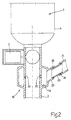
- Fig. 2 shows a detail of Fig. 1 in cross section and on an enlarged scale;
- Fig. 3 is a diagrammatic and perspective view of a further embodiment of the intake manifold of Fig. 1.
- In the accompanying drawings, reference numeral 1 designates an intake manifold forming part of an internal combustion engine (known overall and not shown) provided with four cylinders, each of which is connected to the intake manifold 1 by at least one respective intake valve and to an exhaust manifold by at least one respective exhaust valve.
- The intake manifold 1 receives fresh air (i.e. air from the external atmosphere containing approximately 20% oxygen) from an intake device (known and not shown) to which it is connected by a
supply tube 2, and may receive a predetermined quantity of the exhaust gases contained in the exhaust manifold and generated by prior combustion in the cylinders via arecycling duct 3. - The intake manifold 1 comprises a
tubular member 4 having aninner chamber 5 and fourintake ducts 6 which extend parallel to and equally spaced from one another from the lateral surface of thetubular member 4 in order to bring theinner chamber 5 into communication with the respective cylinders. Thesupply tube 2 is connected at an inlet end of thetubular member 4 by means of the interposition of abutterfly valve 7 which is adapted to stop fresh air from entering theinner chamber 5 in particular operating conditions (typically when the engine is off). - The
tubular member 4 is mechanically connected by means of a series of screws (known and not shown) to asupport body 8 which is physically independent from thetubular member 4 and houses therecycling duct 3. In particular, thesupport body 8 is mechanically connected to thetubular member 4 so that it is disposed in the space bounded at the bottom by theintake ducts 6 and laterally by thetubular member 4. - The
support body 8 is U-shaped with tworectilinear sections curved section 11; therectilinear inlet section 9 is disposed above theintake ducts 6, while therectilinear output section 10 is disposed laterally and in the vicinity of thetubular member 4. An initial portion of therectilinear inlet section 9 is connected to the exhaust manifold in order to receive the exhaust gases to be recycled, and an end portion of therectilinear output section 10 is connected to theinner chamber 5 of the intake manifold 1 in order to introduce the recycled exhaust gases into thisinner chamber 5. - The
support body 8 comprises arecycling valve 12 which is adapted to regulate the flow of exhaust gas through therecycling duct 3 and is housed in an initial portion of therectilinear inlet section 9 so as to be disposed at the location of an initial portion of therecycling duct 3. - The
support body 8 further comprises aheat exchanger 13 which is adapted to cool the recycled exhaust gases and is housed along therectilinear inlet section 9 downstream of therecycling valve 12. Theheat exchanger 13 comprises atube 14 folded into a U shape which forms an upper wall of therecycling duct 3 and in which an engine cooling fluid is caused to circulate. - Lastly, the
support body 8 comprises aflow sensor 15 which is adapted to measure the flow of recycled exhaust gases and is housed in a median portion of therectilinear outlet section 10 downstream of theheat exchanger 13. According to the further embodiment shown in Fig. 3, theflow sensor 15 is housed in a final portion of therectilinear inlet section 9 downstream of theheat exchanger 13. - It is important to note that the
flow sensor 15 is preferably housed downstream of theheat exchanger 13, so as cause theflow sensor 15 to work at relatively low temperatures (of some 200°C rather than the 400°C of the exhaust gases from the exhaust manifold) and therefore contain the production costs of thisflow sensor 15. Moreover, theflow sensor 15 is housed along a rectilinear portion of therecycling duct 3 so as to allow thesensor 15 to carry out a measurement with a relatively high precision, as the measurement of a flow sensor is the more precise, the more remotely the flow sensor is positioned from non-rectilinear sections. - As shown in Fig. 1, the intake manifold 1 comprises a
mixing device 18 which is disposed immediately upstream of thetubular member 4 along thesupply tube 2, receives the recycled exhaust gases from therecycling duct 3 and receives fresh air from theintake tube 2. - According to the further embodiment shown in Fig. 3, the
tubular member 4 comprises, for eachintake duct 6, a respective throughhole 16 which is provided in the vicinity of thecorresponding intake duct 6 and brings theinner chamber 5 into communication with therecycling duct 3; similarly, therectilinear output section 10 of thesupport body 8 has, for each throughhole 16, a respective throughhole 17 which is coupled to the corresponding throughhole 16. - As shown in Fig. 2, the
mixing device 18 comprises anannular chamber 19 which surrounds a portion of thesupply tube 2, communicates with thesupply tube 2 via a plurality of radial through holes 20 and receives the recycled exhaust gases from therecycling duct 3. In operation, the exhaust gases from therecycling duct 3 are conveyed to theannular chamber 19 at a pressure that is relatively higher than the intake pressure under the action of the relatively higher pressure in the exhaust manifold; as the fresh air in thesupply tube 2 is substantially at atmospheric pressure, the exhaust gas in theannular chamber 19 enters thesupply tube 2 via the radial through holes 20 and is mixed with the air from the intake line before entering theinner chamber 5 of the intake manifold 1. - An
end tube 21 of therecycling duct 3 is coupled flush with aninlet tube 22 of themixing device 18 by means of afurther connection tube 23 which is coaxial to theend tube 21 and to theinlet tube 22 and is adapted internally to engage, in a fluid-tight manner, both theend tube 21 of therecycling duct 3 and theinlet tube 22 of themixing device 18. Respectiveannular sealing members 24 of elastic material (commonly known as "O-rings") are interposed between theconnection tube 23 and theend tube 21 andinlet tube 22 so as to ensure the leak-tightness of the coupling and at the same time to allow a limited axial sliding between theconnection tube 23 and theend tube 21 andinlet tube 22. This axial sliding is essential to compensate for any imbalances in the heat expansions to which theend tube 21 andinlet tube 22 are subject. - The
mixing device 18 preferably comprises and integrates thebutterfly valve 7 that regulates the intake of the gas mixture into theinner chamber 5 of the intake manifold 1; this integration makes it possible to reduce both the bulk and the overall costs of the intake manifold 1. - According to a possible embodiment, the
support body 8 is made from metal material, in particular aluminium, as it has to provide adequate support for therecycling valve 12 and theheat exchanger 13 and has to operate with gases at relatively high temperatures (the exhaust gases from the exhaust manifold have a temperature of some 400°C); thetubular member 4 is, however, of plastic material, which is light and can be readily moulded, since it operates with gases at relatively low temperatures (the mixture of fresh air and recycled exhaust gas does not exceed 100°C). - According to a further embodiment (not shown), a bypass duct is provided in parallel with the
heat exchanger 13; the passage of the exhaust gases to be recycled through theheat exchanger 13 or through the bypass duct is controlled by therecycling valve 12. In particular, the exhaust gases to be recycled are caused to pass through the bypass duct, thereby avoiding passing though theheat exchanger 13, on ignition of the engine and are subsequently caused to pass through theheat exchanger 13 when the engine has reached a minimum operating temperature threshold.
Claims (21)
- An intake manifold for an internal combustion engine provided with exhaust gas recycling, this intake manifold (1) comprising a tubular member (4) having an inner chamber (5), a plurality of intake ducts (6) which extend parallel to and equally spaced from one another from the lateral surface of the tubular member (4) in order to bring the inner chamber (5) into communication with respective cylinders, and a recycling duct (3) which is housed in a support body (8) and is adapted to receive the exhaust gases from an exhaust manifold so that these exhaust gases can be introduced into the inner chamber (5), the intake manifold (1) being characterised in that the support body (8) is physically independent from the tubular member (4) and is mechanically connected to the tubular member (4) so as to be disposed in the space bounded at the bottom by the intake ducts (6) and laterally by the tubular member (4).
- An intake manifold as claimed in claim 1, in which the support body (8) is U-shaped with two rectilinear sections (9, 10) connected by a curved section (11), a first rectilinear section (9) being disposed above the intake ducts (6) and a second rectilinear section (10) being disposed laterally and in the vicinity of the tubular member (4).
- An intake manifold as claimed in claim 1 or 2, in which the support body (8) comprises a recycling valve (12) adapted to regulate the flow of exhaust gases through the recycling duct (3).
- An intake manifold as claimed in claim 3, in which the recycling valve (12) is housed at the location of an initial portion of the recycling duct (3).
- An intake manifold as claimed in one of claims 1 to 4, in which the support body (8) comprises a heat exchanger (13) adapted to cool the recycled exhaust gases.
- An intake manifold as claimed in claim 5, in which the heat exchanger (13) comprises a tube (14) folded into a U shape in which an engine cooling fluid is caused to flow.
- An intake manifold as claimed in claim 5, in which the tube (14) folded into a U shape forms an upper wall of the recycling duct (3).
- An intake manifold as claimed in one of claims 1 to 7, in which the support body (8) comprises a flow sensor (15) adapted to measure the flow of recycled exhaust gases.
- An intake manifold as claimed in claim 2, in which an initial portion of the first rectilinear section (9) of the support body (8) is connected to the exhaust manifold in order to receive the exhaust gases to be recycled, and an end portion of the second rectilinear section (10) of the support body (8) is connected to the inner chamber (5) in order to introduce the recycled exhaust gases into this inner chamber (5).
- An intake manifold as claimed in claim 9, in which the support body (8) comprises a recycling valve (12) adapted to regulate the flow of exhaust gases through the recycling duct (3), a heat exchanger (13) adapted to cool the recycled exhaust gases and a flow sensor (15) adapted to measure the flow of recycled exhaust gases, the recycling valve (12) being disposed in an initial portion of the first rectilinear section (9) of the support body (8), the heat exchanger (13) being disposed along the first rectilinear section (9) of the support body (8) downstream of the recycling valve (12) and the flow sensor (15) being disposed downstream of the heat exchanger (13).
- An intake manifold as claimed in claim 10, in which the flow sensor (15) is disposed at the location of an end portion of the first rectilinear section (9) of the support body (8).
- An intake manifold as claimed in claim 10, in which the flow sensor (15) is disposed at the location of a median portion of the second rectilinear section (10) of the support body (8).
- An intake manifold as claimed in claim 10, 11 or 12, and comprising a bypass duct in parallel with the heat exchanger (13), the passage of the exhaust gases to be recycled through the heat exchanger (13) or through the bypass duct being controlled by the recycling valve (12).
- An intake manifold as claimed in one of claims 1 to 13, in which the tubular member (4) has, for each intake duct (6), a respective first through hole (16), which is provided in the vicinity of the corresponding intake duct (6) and brings the inner chamber (5) into communication with the recycling duct (3).
- An intake manifold as claimed in claim 14, in which the recycling duct (3) has, for each first through hole (16), a respective second through hole (17) which is coupled to the corresponding first through hole (16).
- An intake manifold as claimed in one of claims 1 to 13, in which the intake manifold comprises a mixing device (18) which is disposed immediately upstream of the tubular member (4), receives the recycled exhaust gases from the recycling duct (3) and receives fresh air from an intake device.
- An intake manifold as claimed in claim 16, in which the mixing device (18) has an annular chamber (19) and is disposed along a supply tube (2), which receives fresh air from the intake device and communicates with the inner chamber (5), the annular chamber (19) surrounding a portion of the supply tube (2), communicating with the supply tube (2) by means of a plurality (20) of radial through holes, and receiving the recycled exhaust gases from the recycling duct (3).
- An intake manifold as claimed in claim 16 or 17, in which an end tube (21) of the recycling duct (3) is coupled flush with an inlet tube (22) of the mixing device (18) by means of a further connection tube (23) which is coaxial to the end tube (21) and the inlet tube (22) and is adapted internally to engage, in a fluid-tight manner, both the end tube (21) of the recycling duct (3) and the inlet tube (22) of the mixing device (18), axial sliding being possible between the connection tube (23) and the end tube (21) and inlet tube (22).
- An intake manifold as claimed in claim 18, in which respective annular sealing members (24) of elastic material are interposed between the connection tube (23) and the end tube (21) and inlet tube (22).
- An intake manifold as claimed in one of claims 16 to 19, in which the mixing device (18) comprises a butterfly valve (7) adapted to regulate the inlet of the gas mixture into the inner chamber (5).
- An intake manifold as claimed in one of claims 1 to 20, in which the support body (8) is made from metal material, in particular aluminium, and the tubular member (4) is made from plastic material.
Applications Claiming Priority (2)
| Application Number | Priority Date | Filing Date | Title |
|---|---|---|---|
| IT2001BO000761A ITBO20010761A1 (en) | 2001-12-14 | 2001-12-14 | INTAKE MANIFOLD FOR AN INTERNAL COMBUSTION ENGINE PROVIDED WITH EXHAUST GAS RECIRCULATION |
| ITBO20010761 | 2001-12-14 |
Publications (2)
| Publication Number | Publication Date |
|---|---|
| EP1319825A1 true EP1319825A1 (en) | 2003-06-18 |
| EP1319825B1 EP1319825B1 (en) | 2007-10-24 |
Family
ID=11439744
Family Applications (1)
| Application Number | Title | Priority Date | Filing Date |
|---|---|---|---|
| EP02027927A Expired - Lifetime EP1319825B1 (en) | 2001-12-14 | 2002-12-13 | Intake manifold for an internal combustion engine provided with exhaust gas recycling |
Country Status (6)
| Country | Link |
|---|---|
| US (1) | US20030136368A1 (en) |
| EP (1) | EP1319825B1 (en) |
| BR (1) | BR0205564B1 (en) |
| DE (1) | DE60223124T2 (en) |
| ES (1) | ES2295280T3 (en) |
| IT (1) | ITBO20010761A1 (en) |
Cited By (3)
| Publication number | Priority date | Publication date | Assignee | Title |
|---|---|---|---|---|
| FR2870893A1 (en) * | 2004-05-25 | 2005-12-02 | Mark Iv Systemes Moteurs Sa | INTEGRATED AIR INTAKE MODULE AND METHOD FOR MANUFACTURING THE SAME |
| EP1533512A3 (en) * | 2003-11-19 | 2006-05-17 | MAHLE Filtersysteme GmbH | Intake device for an internal combustion engine |
| EP1770271A1 (en) * | 2005-09-28 | 2007-04-04 | Kubota Corporation | Multi-cylinder internal combustion engine with EGR-cooler |
Families Citing this family (8)
| Publication number | Priority date | Publication date | Assignee | Title |
|---|---|---|---|---|
| DE10341393B3 (en) * | 2003-09-05 | 2004-09-23 | Pierburg Gmbh | Air induction port system for internal combustion engines has exhaust gas return passage made in one piece with casing, and exhaust gas return valve and throttle valve are constructed as cartridge valve for insertion in holes in casing |
| JP4192763B2 (en) * | 2003-11-07 | 2008-12-10 | 株式会社日立製作所 | Electronic EGR gas control device |
| US7185642B1 (en) * | 2005-08-23 | 2007-03-06 | Detroit Diesel Corporation | Manifold body for an internal combustion engine |
| FR2894297B1 (en) * | 2005-12-01 | 2008-01-04 | Renault Sas | IMPROVED AIR SUPPLY DISTRIBUTOR FOR INTERNAL COMBUSTION ENGINE |
| DE102009053433A1 (en) * | 2009-11-17 | 2011-05-19 | Daimler Ag | Suction tube section and suction system |
| FR2958336B1 (en) * | 2010-03-31 | 2013-03-15 | Valeo Systemes Thermiques | MANIFOLD FOR GAS DISTRIBUTION IN THE CYLINDER HEAD OF AN ENGINE WITH RECIRCULATED EXHAUST GAS MIXTURE WITH COUNTER-CURRENT ADMISSION GASES. |
| US20160169166A1 (en) * | 2014-12-10 | 2016-06-16 | Hyundai Motor Company | Structure of engine system |
| KR20180109195A (en) * | 2017-03-27 | 2018-10-08 | 현대자동차주식회사 | Engine having aluminum egr cooler |
Citations (11)
| Publication number | Priority date | Publication date | Assignee | Title |
|---|---|---|---|---|
| GB2062749A (en) * | 1979-10-09 | 1981-05-28 | Ford Motor Co | Internal Combustion Engine With EGR Cooler |
| EP0363021A1 (en) * | 1988-10-05 | 1990-04-11 | Ford Motor Company Limited | Fast response exhaust gas recirculation (EGR) system |
| JPH0674100A (en) * | 1992-08-28 | 1994-03-15 | Fuji Heavy Ind Ltd | Exhaust gas re-circulation control method for engine |
| US5433183A (en) * | 1993-06-25 | 1995-07-18 | Solvay (Societe Anonyme) | Connection system for connecting a pipe carrying a hot fluid to a plastic member and its use in an internal combustion engine |
| DE19641700C1 (en) * | 1996-10-10 | 1997-10-30 | Daimler Benz Ag | Multiple heat-exchanger used in internal combustion engine |
| JPH10131813A (en) * | 1996-10-31 | 1998-05-19 | Suzuki Motor Corp | Engine gas distribution structure |
| JPH1182197A (en) * | 1997-09-08 | 1999-03-26 | Denso Corp | Intake device for internal combustion engine |
| JP2000080962A (en) * | 1998-09-04 | 2000-03-21 | Mitsubishi Motors Corp | Exhaust gas inlet structure for exhaust gas recirculation system |
| US6138649A (en) * | 1997-09-22 | 2000-10-31 | Southwest Research Institute | Fast acting exhaust gas recirculation system |
| EP1059435A2 (en) * | 1999-06-11 | 2000-12-13 | Pierburg Aktiengesellschaft | Arrangement of intake air conduits for a combustion engine |
| EP1154144A1 (en) * | 2000-05-12 | 2001-11-14 | IVECO FIAT S.p.A. | An internal-combustion engine provided with an exhaust gas recirculation system, in particular for a vehicle |
Family Cites Families (1)
| Publication number | Priority date | Publication date | Assignee | Title |
|---|---|---|---|---|
| US5924398A (en) * | 1997-10-06 | 1999-07-20 | Ford Global Technologies, Inc. | Flow improvement vanes in the intake system of an internal combustion engine |
-
2001
- 2001-12-14 IT IT2001BO000761A patent/ITBO20010761A1/en unknown
-
2002
- 2002-12-11 US US10/316,415 patent/US20030136368A1/en not_active Abandoned
- 2002-12-13 BR BRPI0205564-3A patent/BR0205564B1/en not_active IP Right Cessation
- 2002-12-13 ES ES02027927T patent/ES2295280T3/en not_active Expired - Lifetime
- 2002-12-13 EP EP02027927A patent/EP1319825B1/en not_active Expired - Lifetime
- 2002-12-13 DE DE60223124T patent/DE60223124T2/en not_active Expired - Lifetime
Patent Citations (11)
| Publication number | Priority date | Publication date | Assignee | Title |
|---|---|---|---|---|
| GB2062749A (en) * | 1979-10-09 | 1981-05-28 | Ford Motor Co | Internal Combustion Engine With EGR Cooler |
| EP0363021A1 (en) * | 1988-10-05 | 1990-04-11 | Ford Motor Company Limited | Fast response exhaust gas recirculation (EGR) system |
| JPH0674100A (en) * | 1992-08-28 | 1994-03-15 | Fuji Heavy Ind Ltd | Exhaust gas re-circulation control method for engine |
| US5433183A (en) * | 1993-06-25 | 1995-07-18 | Solvay (Societe Anonyme) | Connection system for connecting a pipe carrying a hot fluid to a plastic member and its use in an internal combustion engine |
| DE19641700C1 (en) * | 1996-10-10 | 1997-10-30 | Daimler Benz Ag | Multiple heat-exchanger used in internal combustion engine |
| JPH10131813A (en) * | 1996-10-31 | 1998-05-19 | Suzuki Motor Corp | Engine gas distribution structure |
| JPH1182197A (en) * | 1997-09-08 | 1999-03-26 | Denso Corp | Intake device for internal combustion engine |
| US6138649A (en) * | 1997-09-22 | 2000-10-31 | Southwest Research Institute | Fast acting exhaust gas recirculation system |
| JP2000080962A (en) * | 1998-09-04 | 2000-03-21 | Mitsubishi Motors Corp | Exhaust gas inlet structure for exhaust gas recirculation system |
| EP1059435A2 (en) * | 1999-06-11 | 2000-12-13 | Pierburg Aktiengesellschaft | Arrangement of intake air conduits for a combustion engine |
| EP1154144A1 (en) * | 2000-05-12 | 2001-11-14 | IVECO FIAT S.p.A. | An internal-combustion engine provided with an exhaust gas recirculation system, in particular for a vehicle |
Non-Patent Citations (4)
| Title |
|---|
| PATENT ABSTRACTS OF JAPAN vol. 018, no. 325 (M - 1625) 21 June 1994 (1994-06-21) * |
| PATENT ABSTRACTS OF JAPAN vol. 1998, no. 10 31 August 1998 (1998-08-31) * |
| PATENT ABSTRACTS OF JAPAN vol. 1999, no. 08 30 June 1999 (1999-06-30) * |
| PATENT ABSTRACTS OF JAPAN vol. 2000, no. 06 22 September 2000 (2000-09-22) * |
Cited By (5)
| Publication number | Priority date | Publication date | Assignee | Title |
|---|---|---|---|---|
| EP1533512A3 (en) * | 2003-11-19 | 2006-05-17 | MAHLE Filtersysteme GmbH | Intake device for an internal combustion engine |
| EP1870591A3 (en) * | 2003-11-19 | 2008-02-20 | Mahle Filtersysteme GmbH | Intake device for an internal combustion engine |
| FR2870893A1 (en) * | 2004-05-25 | 2005-12-02 | Mark Iv Systemes Moteurs Sa | INTEGRATED AIR INTAKE MODULE AND METHOD FOR MANUFACTURING THE SAME |
| US7165539B2 (en) | 2004-05-25 | 2007-01-23 | Mark Iv Systemes Moteurs Societe Anonyme | Integrated air inlet module and its manufacturing process |
| EP1770271A1 (en) * | 2005-09-28 | 2007-04-04 | Kubota Corporation | Multi-cylinder internal combustion engine with EGR-cooler |
Also Published As
| Publication number | Publication date |
|---|---|
| ITBO20010761A1 (en) | 2003-06-16 |
| ES2295280T3 (en) | 2008-04-16 |
| ITBO20010761A0 (en) | 2001-12-14 |
| BR0205564A (en) | 2004-08-03 |
| US20030136368A1 (en) | 2003-07-24 |
| BR0205564B1 (en) | 2011-05-17 |
| DE60223124D1 (en) | 2007-12-06 |
| DE60223124T2 (en) | 2008-08-14 |
| EP1319825B1 (en) | 2007-10-24 |
Similar Documents
| Publication | Publication Date | Title |
|---|---|---|
| EP1319825B1 (en) | Intake manifold for an internal combustion engine provided with exhaust gas recycling | |
| US7921830B2 (en) | Temperature controlled venturi for use with an EGR system in an internal combustion engine | |
| CN1957170B (en) | Control system of exhaust gas circulation system | |
| US4922882A (en) | Crankcase ventilation system | |
| US6478017B2 (en) | Internal-combustion engine provided with an exhaust gas recirculation system, in particular for a vehicle | |
| CN101550892B (en) | Modular exhaust gas recirculation cooling for internal combustion engines | |
| ATE293750T1 (en) | FLUID INTRODUCTION FOR A HOT FLUID IN A CAVITY STRUCTURE | |
| US20070144170A1 (en) | Compressor having integral EGR valve and mixer | |
| US7311090B2 (en) | Engine exhaust gas passage flow orifice and method | |
| WO2007140148A3 (en) | Exhaust gas recirculator mixer | |
| DE69011792D1 (en) | Emission control device. | |
| RU2605489C2 (en) | Venturi flow meter with vacuum insulation for exhaust gas recirculation system | |
| US20130298882A1 (en) | EGR with Temperature Controlled Venturi Flow Meter | |
| US9488628B2 (en) | Gas sensor protection device and method | |
| CN102562371A (en) | Intake system for an internal combustion engine | |
| US6293267B1 (en) | Flow-based control method for an engine control valve | |
| CN208718791U (en) | Turbogenerator and entrance deflation heating system for turbogenerator | |
| CN113661319A (en) | Modular exhaust gas recirculation mixer | |
| CN101449032A (en) | Exhaust and breather device for a supercharged internal combustion engine | |
| GB2431964A (en) | Diesel engine exhaust gas treatment system with a particulate filter and exhaust gas recirculation | |
| DE502005010302D1 (en) | INTERNAL COMBUSTION ENGINE WITH DOUBLE CHARGES AND METHOD FOR OPERATING THEM | |
| CN110219754B (en) | exhaust gas recirculation system | |
| CN118881441A (en) | Ventilation system, methanol engine, vehicle, control method and computer program | |
| US11261767B2 (en) | Bifurcated air induction system for turbocharged engines | |
| SE0501701L (en) | Arrangement and method for recirculating exhaust gases of an internal combustion engine |
Legal Events
| Date | Code | Title | Description |
|---|---|---|---|
| PUAI | Public reference made under article 153(3) epc to a published international application that has entered the european phase |
Free format text: ORIGINAL CODE: 0009012 |
|
| AK | Designated contracting states |
Designated state(s): AT BE BG CH CY CZ DE DK EE ES FI FR GB GR IE IT LI LU MC NL PT SE SI SK TR |
|
| AX | Request for extension of the european patent |
Extension state: AL LT LV MK RO |
|
| 17P | Request for examination filed |
Effective date: 20031209 |
|
| AKX | Designation fees paid |
Designated state(s): DE ES FR GB SE |
|
| GRAP | Despatch of communication of intention to grant a patent |
Free format text: ORIGINAL CODE: EPIDOSNIGR1 |
|
| GRAS | Grant fee paid |
Free format text: ORIGINAL CODE: EPIDOSNIGR3 |
|
| GRAA | (expected) grant |
Free format text: ORIGINAL CODE: 0009210 |
|
| RAP1 | Party data changed (applicant data changed or rights of an application transferred) |
Owner name: MAGNETI MARELLI POWERTRAIN S.P.A. |
|
| AK | Designated contracting states |
Kind code of ref document: B1 Designated state(s): DE ES FR GB SE |
|
| REG | Reference to a national code |
Ref country code: GB Ref legal event code: FG4D |
|
| REF | Corresponds to: |
Ref document number: 60223124 Country of ref document: DE Date of ref document: 20071206 Kind code of ref document: P |
|
| REG | Reference to a national code |
Ref country code: SE Ref legal event code: TRGR |
|
| REG | Reference to a national code |
Ref country code: ES Ref legal event code: FG2A Ref document number: 2295280 Country of ref document: ES Kind code of ref document: T3 |
|
| ET | Fr: translation filed | ||
| PLBE | No opposition filed within time limit |
Free format text: ORIGINAL CODE: 0009261 |
|
| STAA | Information on the status of an ep patent application or granted ep patent |
Free format text: STATUS: NO OPPOSITION FILED WITHIN TIME LIMIT |
|
| 26N | No opposition filed |
Effective date: 20080725 |
|
| PGFP | Annual fee paid to national office [announced via postgrant information from national office to epo] |
Ref country code: ES Payment date: 20091203 Year of fee payment: 8 Ref country code: SE Payment date: 20091125 Year of fee payment: 8 |
|
| PGFP | Annual fee paid to national office [announced via postgrant information from national office to epo] |
Ref country code: GB Payment date: 20091125 Year of fee payment: 8 |
|
| GBPC | Gb: european patent ceased through non-payment of renewal fee |
Effective date: 20101213 |
|
| REG | Reference to a national code |
Ref country code: SE Ref legal event code: EUG |
|
| PG25 | Lapsed in a contracting state [announced via postgrant information from national office to epo] |
Ref country code: SE Free format text: LAPSE BECAUSE OF NON-PAYMENT OF DUE FEES Effective date: 20101214 |
|
| PG25 | Lapsed in a contracting state [announced via postgrant information from national office to epo] |
Ref country code: GB Free format text: LAPSE BECAUSE OF NON-PAYMENT OF DUE FEES Effective date: 20101213 |
|
| REG | Reference to a national code |
Ref country code: ES Ref legal event code: FD2A Effective date: 20120305 |
|
| PG25 | Lapsed in a contracting state [announced via postgrant information from national office to epo] |
Ref country code: ES Free format text: LAPSE BECAUSE OF NON-PAYMENT OF DUE FEES Effective date: 20101214 |
|
| PGFP | Annual fee paid to national office [announced via postgrant information from national office to epo] |
Ref country code: DE Payment date: 20141121 Year of fee payment: 13 |
|
| PGFP | Annual fee paid to national office [announced via postgrant information from national office to epo] |
Ref country code: FR Payment date: 20141217 Year of fee payment: 13 |
|
| REG | Reference to a national code |
Ref country code: DE Ref legal event code: R119 Ref document number: 60223124 Country of ref document: DE |
|
| REG | Reference to a national code |
Ref country code: FR Ref legal event code: ST Effective date: 20160831 |
|
| PG25 | Lapsed in a contracting state [announced via postgrant information from national office to epo] |
Ref country code: DE Free format text: LAPSE BECAUSE OF NON-PAYMENT OF DUE FEES Effective date: 20160701 |
|
| PG25 | Lapsed in a contracting state [announced via postgrant information from national office to epo] |
Ref country code: FR Free format text: LAPSE BECAUSE OF NON-PAYMENT OF DUE FEES Effective date: 20151231 |