EP1319509A1 - Roller holding apparatus of printing press - Google Patents
Roller holding apparatus of printing press Download PDFInfo
- Publication number
- EP1319509A1 EP1319509A1 EP02027679A EP02027679A EP1319509A1 EP 1319509 A1 EP1319509 A1 EP 1319509A1 EP 02027679 A EP02027679 A EP 02027679A EP 02027679 A EP02027679 A EP 02027679A EP 1319509 A1 EP1319509 A1 EP 1319509A1
- Authority
- EP
- European Patent Office
- Prior art keywords
- roller
- arm
- printing press
- holding apparatus
- holder
- Prior art date
- Legal status (The legal status is an assumption and is not a legal conclusion. Google has not performed a legal analysis and makes no representation as to the accuracy of the status listed.)
- Granted
Links
Images




Classifications
-
- B—PERFORMING OPERATIONS; TRANSPORTING
- B41—PRINTING; LINING MACHINES; TYPEWRITERS; STAMPS
- B41F—PRINTING MACHINES OR PRESSES
- B41F31/00—Inking arrangements or devices
- B41F31/30—Arrangements for tripping, lifting, adjusting, or removing inking rollers; Supports, bearings, or forks therefor
-
- B—PERFORMING OPERATIONS; TRANSPORTING
- B41—PRINTING; LINING MACHINES; TYPEWRITERS; STAMPS
- B41P—INDEXING SCHEME RELATING TO PRINTING, LINING MACHINES, TYPEWRITERS, AND TO STAMPS
- B41P2213/00—Arrangements for actuating or driving printing presses; Auxiliary devices or processes
- B41P2213/80—Means enabling or facilitating exchange of cylinders
- B41P2213/804—Means enabling or facilitating exchange of cylinders radially
Definitions
- This invention relates to a holding apparatus for a roller, such as an ink roller, in a printing press such as a rotary press.
- a lever 101 is pivotally supported on a shaft of an adjacent ink roller 100.
- An ink roller 103 which is present at a position where the ink roller 103 is difficult to replace, is supported by the lever 101 via a bearing 102.
- the ink roller 103 which is located at a position where it is difficult to replace, is moved to a position where it is easy to replace. At this position, the ink roller 103 is replaced.
- an air cylinder 104 is used for adjusting nip pressure against a plate cylinder and the roller adjacent to the ink roller 103 located at the position where its replacement is difficult.
- a connecting mechanism 105 for connecting the lever 101 to the air cylinder 104 must be provided, making the entire mechanism complicated.
- a screw (not shown) of the connecting mechanism 105 has to be turned manually and undone. A work load is imposed on an operator, and it takes time to replace the ink roller.
- an automatic nip pressure adjusting mechanism for an adjacent roller there is, for example, one as shown in FIG. 12 (Japanese Utility Model Registration No. 2588289).
- a slot 202 is provided in an arm 201 supported on an adjacent roller 200, a protuberance 205 is provided on a holder 204 of a roller 203, and a hole is provided in a front end portion of the protuberance 205.
- the protuberance 205 of the holder 204 is inserted through the slot 202 of the arm 201, and a rod 207 supported by a pin 206 supported by the arm 201 is inserted through the hole of the protuberance 205 of the holder 204.
- a helical compression spring 209 is provided between the protuberance 205 of the holder 204 and a locking nut 208 of the rod 207.
- the automatic nip pressure adjusting mechanism is large in the number of the components, high in the cost, and complicated in the mechanism. Provision of this automatic nip pressure adjusting mechanism in the surroundings of the ink roller 103 located at the aforementioned position, where the replacement of the ink roller 103 is difficult, presents difficulty in terms of space, and is not acceptable at all.
- the present invention has been accomplished to solve the above-described problems with the earlier technologies. It is the object of the invention to provide a roller holding apparatus of a printing press which can perform roller replacement easily and promptly with a simple structure, and which can always retain a set nip pressure.
- a roller holding apparatus of a printing press comprising:
- roller replacement can be performed easily and quickly with a simple structure, and a set nip pressure can be always retained.
- the pressing member may urge the second roller toward the first roller by a first elastic member.
- the pressing member may comprise a first depression provided in the holder on a side of the second roller; a first hole provided in the holder and communicating with the first depression; a first pin inserted into the first hole and provided with a contact portion in contact with the second roller; and a first elastic member'interposed between the bottom of the first depression and the contact portion of the first pin.
- the pressing member may further comprise pressing force adjusting means for adjusting the pressing force of the pressing member.
- the pressing member having the pressing force adjusting means may comprise a first hole provided in the holder and having a threaded portion provided in the inside thereof; an adjusting screw screwed into the threaded portion of the first hole and having a hole; a first pin inserted into the hole of the adjusting screw and having a contact portion in contact with the second roller; and a first elastic member interposed between the adjusting screw and the contact portion of the first pin.
- the roller holding apparatus of a printing press may further comprise a second hole provided in one of the arm and the holder; a second pin provided in the other of the arm and the holder; and a second elastic member for urging the second pin toward the second hole.
- the roller holding apparatus of a printing press may further comprise holding means for holding the arm at a replacement position where the second roller is replaced, and at a printing position where the second roller contacts a third roller.
- the holding means may include first and second brackets fixed to a frame of the printing press; depressions provided in the first and second brackets or in the arm; and a fixing pin provided in the arm if the depressions are provided in the first and second brackets, or the fixing pin being provided in the first and second brackets if the depressions are provided in the arm, and the fixing pin being insertable into the depression provided in the first and second brackets or in the arm.
- the holding means may include a stopper member fixed to a frame of the printing press; a stopper portion provided in the arm; and an actuator pivotally supported by the arm.
- the holding means may include a stopper member fixed to a frame of the printing press; a stopper portion provided in the arm; and a second elastic member pivotally supported by the arm.
- the arm may be provided with a handgrip for swinging the arm.
- the arm may be supported so as to be swingable between a printing position where the second roller is in contact with the first roller and a third roller and printing is performed, and a replacement position where the second roller is separated from the third roller and the second roller is replaced.
- the holder may be supported so as to be swingable between a holding position where the second roller is held by the arm, and a release position where the second roller can be replaced from and mounted on the arm, and the holder may be swung to the release position, with the arm being located at the replacement position, whereby the second roller can be replaced.
- the pressing member may, at least, include a spring, and the arm may be located at the printing position, whereby a constant pressure against the first roller and the third roller is imparted to the second roller by the spring.
- FIG. 1 is a side view of the essential parts of an inking device showing a first embodiment of the present invention.
- FIG. 2 is a developed plan view of the essential parts of the inking device.
- FIGS. 3(a) to 3(c) are views illustrating actions of the essential parts of the inking device.
- FIG. 4 is a side view of an inking unit of the inking device.
- ink rollers 2 in an inking device (inking unit) 1 of a rotary press capable of rainbow printing as shown in FIG. 4, a rubber roller (second roller) 2c disposed between metal rollers (first and third rollers) 2a and 2b can be replaced where necessary.
- the rubber roller 2c in the lowest stage at a position, where it is difficult to replace, can be moved by the present roller holding apparatus between a printing position and a replacement/mounting position, as indicated by arrows in the drawing.
- the metal roller 2a is rotatably supported between right and left frames 3 of the inking device 1 via bearings 4.
- a driving force is transmitted from a drive source (not shown) via gears 5 joined to the shaft ends of the metal roller 2a.
- Triangular roller arms 6 are pivotally (swingably) supported at shaft portions on both sides of a roller body of the metal roller 2a located inwardly of the bearings 4. Front portions of the roller arms 6 are connected by a width determining/reinforcing handgrip 7, while rear portions of the roller arms 6 are connected by a width determining/reinforcing stay 8.
- a bearing support portion 9 is provided on the inner surface of an intermediate portion of each of the roller arms 6.
- the rubber roller 2c is rotatably supported between the bearing support portions 9 via bearings 10.
- Right and left holders 11, as a pair, each in the shape of a bell crank (to be described later) enable the rubber roller 2c to be mounted on and dismounted from the roller arms 6, together with the bearings 10.
- the holder 11 is pivotally (swingably) supported at one end portion thereof by a pin 12.
- a positioning pin (second pin) 13 provided in an intermediate portion of the holder 11 is inserted into and engaged with an engagement hole (second hole) 14 formed in the roller arm 6.
- the positioning pin 13 is always urged by a compression spring (second elastic member) 15 in a direction in which the positioning pin 13 protrudes from the holder 11 toward the roller arm 6.
- the holder 11 When, at the replacement/mounting position of the rubber roller 2c (see chain lines shown in FIG. 1), the holder 11 is pivoted (swung) clockwise in FIG. 1 until it hits an engagement pin (stopper pin) 16 formed on the roller arm 6, the holder 11 is stably fixed at this position, and the rubber roller 2c can be replaced from and mounted on the roller arm 6.
- a pressing member 17 for pressing the rubber roller 2c against the metal rollers 2a, 2b via an elastic member is provided in the other end portion of the holder 11.
- the pressing member 17 comprises a depression (first depression) 18 provided in the holder 11 on a side of the rubber roller 2c, a hole (first hole) 19 provided in the holder 11 and communicating with the depression 18, a pin (first pin) 20 inserted into the hole 19 and having a contact portion 20a contacting the bearing 10 of the rubber roller 2c, and a compression spring (first elastic member) 21 interposed between the bottom of the depression 18 and the contact portion 20a of the pin 20.
- a stopper 20b is provided in the pin 20. The stopper 20b is designed to prevent the pin 20 from slipping out of the holder 11 when the holder 11 is pivoted (swung) from the position of FIG. 3(b) to the position of FIG. 3(a).
- the bearing 10 of the rubber roller 2c is pressed in the bearing support portion 9 in a predetermined direction by the compression spring 21, whereby the nip pressure of the rubber roller 2c against the metal rollers 2a, 2b is always kept constant.
- the roller arm 6 is selectively positioned and fixed by holding means at the printing position and the replacement/mounting position of the rubber roller 2c.
- the holding means comprises a printing position fixing bracket 22 and a replacement/mounting position fixing bracket 23 secured to each of the right and left frames 3, depressions 24 and 25 provided in the brackets 22 and 23 (or the roller arm 6), a fixing pin 26 provided in the roller arm 6 (or the brackets 22 and 23) and insertable into the depression 24 or 25, and handle-equipped pivot covers 27 and 28 capable of closing the depressions 24 and 25 while the fixing pin 26 is being inserted into the depression 24 or 25.
- roller holding apparatus of the present invention is constructed as described above. Next, its actions will be described with reference to FIGS. 3(a) to 3(c).
- the roller arm 6 is positioned and fixed at the printing position fixing bracket 22 via the fixing pin 26 as stated earlier.
- the rubber roller 2c is held by the holder 11 so as to be unremovable from the roller arm 6, and is brought into contact with the metal rollers 2a and 2b by being elastically urged by the pressing member 17 provided in the holder 11 as stated earlier.
- the nip pressure which affects printing quality, is always constant and requires no adjusting operation, even if the roller diameter changes, for example, as a result of thermal expansion.
- the holder 11 is pivoted (swung) clockwise about the pin 12 to make contact with the engaging pin 16. At this position, the holder 11 is fixed stably, as stated previously.
- roller arm 6 equipped with the holder 11 requiring no nip pressure adjusting operation is pivoted (swung) about the shaft portion of the metal roller 2a, the rubber roller 2c is moved from the position where it is difficult to replace, to the position where it is easy to replace. Hence, roller replacement can be performed easily and quickly.
- handles of the pivot covers 27 and 28, and the handgrip 7, etc. are incorporated as components, so that no special tools are needed.
- the rubber roller 2c is adapted to roll on the metal roller 2a (FIGS. 3(b) to 3(c)).
- the rubber roller 2c need not roll on the metal roller 2a, and may make contact with the metal roller 2a (or metal rollers 2a, 2b) at the position shown in FIG. 3(c) (the rotation center of the roller arm may be eccentric with respect to the axis of the metal roller).
- the roller arm 6 may be free to pivot (swing) relative to the frame 3.
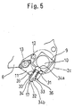
- FIG. 5 is a side view of the holder portion showing a second embodiment of the present invention.
- the pressing member 17 of the holder 11 in the first embodiment is provided with pressing force adjusting means for adjusting the pressing force of the pressing member 17.
- the pressing member 17 comprises a hole (first hole) 31 provided in the holder 11 and having a threaded portion 30 formed in the inside thereof; an adjusting screw 33 screwed into the threaded portion 30 of the hole 31 and provided with a hole 32; a pin (first pin) 34 inserted into the hole 32 of the adjusting screw 33 and having a contact portion 34a in contact with the rubber roller 2c; a compression spring (first elastic member) 35 interposed between the adjusting screw 33 and the contact portion 34a of the pin 34; and a locking nut 36 for preventing the loosening of the adjusting screw 33.
- a stopper 34b is provided in the pin 34.
- the stopper 34b is designed to prevent the pin 34 from escaping from the holder 11 when the holder 11 is pivoted (swung) from the position of FIG. 3(b) to the position of FIG. 3(a).
- Other constructions are the same as in the first embodiment.
- the degree to which the adjusting screw 33 is screwed in is changed, whereby the spring load of the compression spring 35 is varied.
- the pressing force of the pressing member 17 is changed, whereby the nip pressure of the rubber roller 2c against the metal rollers 2a, 2b can be adjusted arbitrarily.
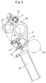
- FIG. 6 is a side view of the essential parts of an inking device showing a third embodiment of the present invention.
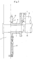
- FIG. 7 is a developed plan view of the essential parts of the inking device.
- the holding means in the first embodiment for selectively positioning and fixing the roller arm 6 at the printing position and the replacement/mounting position of the rubber roller 2c is composed of a stopper member 40 fixed on the frame 3 and positionally adjustable by the degree of screwing-in; a stopper portion 41 provided in the roller arm 6 and capable of contacting the stopper member 40; and an air cylinder (actuator) 42 having a piston rod front end pivotally connected to the roller arm 6 and a cylinder portion pivotally supported by the frame 3.
- actuator air cylinder
- the air cylinder 42 is contracted to bring the stopper portion 41 into contact with the stopper member 40, whereby the roller arm 6 can be held at the printing position of the rubber roller 2c (see solid lines shown in FIG. 6).
- the air cylinder 42 is expanded, whereby the roller arm 6 can be held at the replacement/mounting position of the rubber roller 2c (see chain lines shown in FIG. 6). This actuation of the air cylinder 42 can be performed by remote control.
- the stopper member 40, the stopper portion 41, and the air cylinder 42 constitute the holding means.
- the holding means holds the roller arm 6 by the stopper member 40, the stopper portion 41, and the air cylinder 42 when the rubber roller 2c is located at the printing position.
- the holding means holds the roller arm 6 by the air cylinder 42.
- the roller arm 6 is pivoted (swung) by the air cylinder 42, but a handgrip may be provided as in the other embodiments. Furthermore, a surface of the roller arm 6, which defines the stopper portion 41, is brought into contact with the stopper member 40. However, a bracket may be mounted on the roller arm 6, and this bracket may make contact with the stopper member 40.
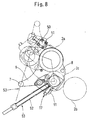
- FIG. 8 is a side view of the essential parts of an inking device showing a fourth embodiment of the present invention.
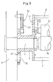
- FIG. 9 is a developed plan view of the essential parts of the inking device.
- the holding means in the first embodiment for selectively positioning and fixing the roller arm 6 at the printing position and the replacement/mounting position of the rubber roller 2c is composed of a stopper member 50 fixed on the frame 3 and positionally adjustable by the degree of screwing-in; a stopper portion 51 provided in the roller arm 6 and capable of contacting the stopper member 50; and a roller arm urging/fixing member (third elastic member) 53 provided with a compression spring 52 and having an operating end pivotally connected to the roller arm 6.
- Other constructions are the same as in the first embodiment.
- the roller arm 6 is automatically and selectively positioned and fixed at the printing position and the replacement/mounting position of the rubber roller 2c under the spring force of the compression spring 52. That is, when the handgrip 7 is brought to a solid-line position shown in FIG. 8, the stopper portion 51 is brought into contact with the stopper member 50 by the spring force of the roller arm urging/fixing member 53 equipped with the compression spring 52, whereby the roller arm 6 can be held at the printing position of the rubber roller 2c (see solid lines shown in FIG. 8). On the other hand, the handgrip 7 is brought to a chain-line position shown in FIG. 8 by once contracting the compression spring 52 during the pivoting (swinging) of the roller arm 6.
- the roller arm 6 can be held at the replacement/mounting position (see chain lines shown in FIG. 8) of the rubber roller 2c by the spring force of the roller arm urging/fixing member 53 equipped with the compression spring 52.
- a stopper (not shown) for confining the roller arm 6 to this position may be provided in the frame 3.
- the stopper member 50, the stopper portion 51, and the roller arm urging/fixing member 53, equipped with the compression spring 52 constitute the holding means.
- the holding means holds the roller arm 6 by the stopper member 50, the stopper portion 51, and the roller arm urging/fixing member 53 equipped with the compression spring 52, when the rubber roller 2c is located at the printing position.
- the holding means holds the roller arm 6 by the roller arm urging/fixing member 53 equipped with the compression spring 52.
- FIG. 10 is a side view of the essential parts of an inking device showing a fifth embodiment of the present invention.
- the handgrip 7 in the fourth embodiment is channel-shaped when viewed in a front view. Its right and left end shaft portions 60 are pivotally supported on the frame 3 (see FIG. 9).
- a lever 61 is integrally connected to the shaft portion 60.
- An arcuate link 63 has one end portion pivotally connected to the front end of the lever 61 by a pin 62, and has the other end portion pivotally connected to the roller arm 6 by a pin 64.
- the roller arm 6 is pivoted (swung) from the printing position of the rubber roller 2c (see solid lines shown in FIG. 10) to the replacement/mounting position of the rubber roller 2c (see chain lines shown in FIG. 10) (or vice versa) via the lever 6 and the arcuate link 63.
- Other constructions are the same as in the fourth embodiment.
- the same actions and effects as in the fourth embodiment are produced, and the degree of freedom is present in the disposition of the handgrip 7.
- the handgrip 7 can be disposed easily at a position where it is easy to handle.
Landscapes
- Inking, Control Or Cleaning Of Printing Machines (AREA)
Abstract
Description
- The entire disclosure of Japanese Patent Application No. 2001-382503 filed on December 17, 2001 including specification, claims, drawings and summary is incorporated herein by reference in its entirety.
- This invention relates to a holding apparatus for a roller, such as an ink roller, in a printing press such as a rotary press.
- In a rotary press or the like, there-has so far been a device, as shown, for example, in FIG. 11 (see Japanese Unexamined Patent Publication No. 2000-94648), for replacing an ink roller which is located at a position where the ink roller is difficult to replace.
- In this replacing device, a
lever 101 is pivotally supported on a shaft of anadjacent ink roller 100. Anink roller 103, which is present at a position where theink roller 103 is difficult to replace, is supported by thelever 101 via abearing 102. By turning thelever 101, theink roller 103, which is located at a position where it is difficult to replace, is moved to a position where it is easy to replace. At this position, theink roller 103 is replaced. - In this device, however, an
air cylinder 104 is used for adjusting nip pressure against a plate cylinder and the roller adjacent to theink roller 103 located at the position where its replacement is difficult. Thus, aconnecting mechanism 105 for connecting thelever 101 to theair cylinder 104 must be provided, making the entire mechanism complicated. Moreover, whenever theink roller 103, located at the position where its replacement is difficult, is moved to the position where its replacement is easy, a screw (not shown) of theconnecting mechanism 105 has to be turned manually and undone. A work load is imposed on an operator, and it takes time to replace the ink roller. - As an automatic nip pressure adjusting mechanism for an adjacent roller, there is, for example, one as shown in FIG. 12 (Japanese Utility Model Registration No. 2588289).
- In this automatic nip pressure adjusting mechanism, a
slot 202 is provided in anarm 201 supported on anadjacent roller 200, aprotuberance 205 is provided on aholder 204 of aroller 203, and a hole is provided in a front end portion of theprotuberance 205. Theprotuberance 205 of theholder 204 is inserted through theslot 202 of thearm 201, and arod 207 supported by apin 206 supported by thearm 201 is inserted through the hole of theprotuberance 205 of theholder 204. Ahelical compression spring 209 is provided between theprotuberance 205 of theholder 204 and alocking nut 208 of therod 207. Thus, the automatic nip pressure adjusting mechanism is large in the number of the components, high in the cost, and complicated in the mechanism. Provision of this automatic nip pressure adjusting mechanism in the surroundings of theink roller 103 located at the aforementioned position, where the replacement of theink roller 103 is difficult, presents difficulty in terms of space, and is not acceptable at all. - The present invention has been accomplished to solve the above-described problems with the earlier technologies. It is the object of the invention to provide a roller holding apparatus of a printing press which can perform roller replacement easily and promptly with a simple structure, and which can always retain a set nip pressure.
- According to the present invention, for attaining the above object, there is provided a roller holding apparatus of a printing press, comprising:
- a first roller supported rotatably;
- an arm supported swingably;
- a holder, swingably supported by the arm, for holding a second roller so as to be detachably mounted on the arm; and
- a pressing member, provided in the holder, for pressing the second roller against the first roller.
-
- According to this feature, roller replacement can be performed easily and quickly with a simple structure, and a set nip pressure can be always retained.
- In the roller holding apparatus of a printing press, the pressing member may urge the second roller toward the first roller by a first elastic member.
- In the roller holding apparatus of a printing press, the pressing member may comprise a first depression provided in the holder on a side of the second roller; a first hole provided in the holder and communicating with the first depression; a first pin inserted into the first hole and provided with a contact portion in contact with the second roller; and a first elastic member'interposed between the bottom of the first depression and the contact portion of the first pin.
- In the roller holding apparatus of a printing press, the pressing member may further comprise pressing force adjusting means for adjusting the pressing force of the pressing member.
- In the roller holding apparatus of a printing press, the pressing member having the pressing force adjusting means may comprise a first hole provided in the holder and having a threaded portion provided in the inside thereof; an adjusting screw screwed into the threaded portion of the first hole and having a hole; a first pin inserted into the hole of the adjusting screw and having a contact portion in contact with the second roller; and a first elastic member interposed between the adjusting screw and the contact portion of the first pin.
- The roller holding apparatus of a printing press may further comprise a second hole provided in one of the arm and the holder; a second pin provided in the other of the arm and the holder; and a second elastic member for urging the second pin toward the second hole.
- The roller holding apparatus of a printing press may further comprise holding means for holding the arm at a replacement position where the second roller is replaced, and at a printing position where the second roller contacts a third roller.
- In the roller holding apparatus of a printing press , the holding means may include first and second brackets fixed to a frame of the printing press; depressions provided in the first and second brackets or in the arm; and a fixing pin provided in the arm if the depressions are provided in the first and second brackets, or the fixing pin being provided in the first and second brackets if the depressions are provided in the arm, and the fixing pin being insertable into the depression provided in the first and second brackets or in the arm.
- In the roller holding apparatus of a printing press, the holding means may include a stopper member fixed to a frame of the printing press; a stopper portion provided in the arm; and an actuator pivotally supported by the arm.
- In the roller holding apparatus of a printing press, the holding means may include a stopper member fixed to a frame of the printing press; a stopper portion provided in the arm; and a second elastic member pivotally supported by the arm.
- In the roller holding apparatus of a printing press , the arm may be provided with a handgrip for swinging the arm.
- In the roller holding apparatus of a printing press, the arm may be supported so as to be swingable between a printing position where the second roller is in contact with the first roller and a third roller and printing is performed, and a replacement position where the second roller is separated from the third roller and the second roller is replaced.
- In the roller holding apparatus of a printing press, the holder may be supported so as to be swingable between a holding position where the second roller is held by the arm, and a release position where the second roller can be replaced from and mounted on the arm, and the holder may be swung to the release position, with the arm being located at the replacement position, whereby the second roller can be replaced.
- In the roller holding apparatus of a printing press , the pressing member may, at least, include a spring, and the arm may be located at the printing position, whereby a constant pressure against the first roller and the third roller is imparted to the second roller by the spring.
- The present invention will become more fully understood from the detailed description given hereinbelow and the accompanying drawings which are given by way of illustration only, and thus are not limitative of the present invention, and wherein:
- FIG. 1 is a side view of the essential parts of an inking device showing a first embodiment of the present invention;
- FIG. 2 is a partly cutaway, developed plan view of the essential parts of the inking device;
- FIGS. 3(a) to 3(c) are views illustrating actions of the essential parts of the inking device;
- FIG. 4 is a side view of an inking unit of the inking device;
- FIG. 5 is a side view of a holder portion showing a second embodiment of the present invention;
- FIG. 6 is a side view of the essential parts of an inking device showing a third embodiment of the present invention;
- FIG. 7 is a partly cutaway, developed plan view of the essential parts of the inking device;
- FIG. 8 is a side view of the essential parts of an inking device showing a fourth embodiment of the present invention;
- FIG. 9 is a partly cutaway, developed plan view of the essential parts of the inking device;
- FIG. 10 is a side view of the essential parts of an inking device showing a fifth embodiment of the present invention;
- FIG. 11 is a partly cutaway, front view of a conventional roller holding apparatus; and
- FIG. 12 is a partly cutaway, front view of a conventional nip pressure adjusting device.
-
- Preferred embodiments of the roller holding apparatus of the printing press according to the present invention will now be described in detail with reference to the accompanying drawings, which in no way limit the invention.
- FIG. 1 is a side view of the essential parts of an inking device showing a first embodiment of the present invention. FIG. 2 is a developed plan view of the essential parts of the inking device. FIGS. 3(a) to 3(c) are views illustrating actions of the essential parts of the inking device. FIG. 4 is a side view of an inking unit of the inking device.
- Of
ink rollers 2 in an inking device (inking unit) 1 of a rotary press capable of rainbow printing, as shown in FIG. 4, a rubber roller (second roller) 2c disposed between metal rollers (first and third rollers) 2a and 2b can be replaced where necessary. Therubber roller 2c in the lowest stage at a position, where it is difficult to replace, can be moved by the present roller holding apparatus between a printing position and a replacement/mounting position, as indicated by arrows in the drawing. - A detailed description will be presented by reference to FIGS. 1 and 2. The
metal roller 2a is rotatably supported between right and leftframes 3 of theinking device 1 viabearings 4. A driving force is transmitted from a drive source (not shown) viagears 5 joined to the shaft ends of themetal roller 2a. -
Triangular roller arms 6 are pivotally (swingably) supported at shaft portions on both sides of a roller body of themetal roller 2a located inwardly of thebearings 4. Front portions of theroller arms 6 are connected by a width determining/reinforcinghandgrip 7, while rear portions of theroller arms 6 are connected by a width determining/reinforcingstay 8. - A
bearing support portion 9 is provided on the inner surface of an intermediate portion of each of theroller arms 6. Therubber roller 2c is rotatably supported between the bearingsupport portions 9 viabearings 10. Right and leftholders 11, as a pair, each in the shape of a bell crank (to be described later) enable therubber roller 2c to be mounted on and dismounted from theroller arms 6, together with thebearings 10. - The
holder 11 is pivotally (swingably) supported at one end portion thereof by apin 12. A positioning pin (second pin) 13 provided in an intermediate portion of theholder 11 is inserted into and engaged with an engagement hole (second hole) 14 formed in theroller arm 6. By these means, therubber roller 2c is unremovably held by theroller arm 6. Thepositioning pin 13 is always urged by a compression spring (second elastic member) 15 in a direction in which thepositioning pin 13 protrudes from theholder 11 toward theroller arm 6. - When, at the replacement/mounting position of the
rubber roller 2c (see chain lines shown in FIG. 1), theholder 11 is pivoted (swung) clockwise in FIG. 1 until it hits an engagement pin (stopper pin) 16 formed on theroller arm 6, theholder 11 is stably fixed at this position, and therubber roller 2c can be replaced from and mounted on theroller arm 6. - A pressing
member 17 for pressing therubber roller 2c against themetal rollers holder 11. In the illustrated embodiment, the pressingmember 17 comprises a depression (first depression) 18 provided in theholder 11 on a side of therubber roller 2c, a hole (first hole) 19 provided in theholder 11 and communicating with thedepression 18, a pin (first pin) 20 inserted into the hole 19 and having acontact portion 20a contacting the bearing 10 of therubber roller 2c, and a compression spring (first elastic member) 21 interposed between the bottom of thedepression 18 and thecontact portion 20a of thepin 20. Astopper 20b is provided in thepin 20. Thestopper 20b is designed to prevent thepin 20 from slipping out of theholder 11 when theholder 11 is pivoted (swung) from the position of FIG. 3(b) to the position of FIG. 3(a). - Thus, at the printing position of the
rubber roller 2c (see solid lines shown in FIG. 1), the bearing 10 of therubber roller 2c is pressed in thebearing support portion 9 in a predetermined direction by the compression spring 21, whereby the nip pressure of therubber roller 2c against themetal rollers - The
roller arm 6 is selectively positioned and fixed by holding means at the printing position and the replacement/mounting position of therubber roller 2c. In the illustrated embodiment, the holding means comprises a printingposition fixing bracket 22 and a replacement/mountingposition fixing bracket 23 secured to each of the right and leftframes 3,depressions brackets 22 and 23 (or the roller arm 6), a fixingpin 26 provided in the roller arm 6 (or thebrackets 22 and 23) and insertable into thedepression depressions pin 26 is being inserted into thedepression - The roller holding apparatus of the present invention is constructed as described above. Next, its actions will be described with reference to FIGS. 3(a) to 3(c).
- At the printing position of the
rubber roller 2c, as shown in FIG. 3(c), theroller arm 6 is positioned and fixed at the printingposition fixing bracket 22 via the fixingpin 26 as stated earlier. - In this state, the
rubber roller 2c is held by theholder 11 so as to be unremovable from theroller arm 6, and is brought into contact with themetal rollers member 17 provided in theholder 11 as stated earlier. - Under this urging force, the nip pressure (width), which affects printing quality, is always constant and requires no adjusting operation, even if the roller diameter changes, for example, as a result of thermal expansion.
- When the
rubber roller 2c is to be replaced because of wear or the like, the engagement between the fixingpin 26 and the printingposition fixing bracket 22 is released, then thehandgrip 7 is gripped and moved to pivot (swing) theroller arm 6 clockwise about the shaft portion of themetal roller 2a, thereby positioning and fixing theroller arm 6 at the replacement/mountingposition fixing bracket 23 via the fixingpin 26, as shown in FIG. 3(b). - At this time, the positional relation between the
holder 11 and theroller arm 6 remains unchanged, so that therubber roller 2c does not leave themetal roller 2a even when theroller arm 6 pivots (swings). - Then, as shown in FIG. 3(a), the
holder 11 is pivoted (swung) clockwise about thepin 12 to make contact with the engagingpin 16. At this position, theholder 11 is fixed stably, as stated previously. - Consequently, the
rubber roller 2c, together with thebearings 10, can be replaced and mounted relative to theroller arm 6. - According to the above-described simple structure in which the
roller arm 6 equipped with theholder 11 requiring no nip pressure adjusting operation is pivoted (swung) about the shaft portion of themetal roller 2a, therubber roller 2c is moved from the position where it is difficult to replace, to the position where it is easy to replace. Hence, roller replacement can be performed easily and quickly. - Also, the handles of the pivot covers 27 and 28, and the
handgrip 7, etc. are incorporated as components, so that no special tools are needed. - In the foregoing embodiment, the
rubber roller 2c is adapted to roll on themetal roller 2a (FIGS. 3(b) to 3(c)). However, therubber roller 2c need not roll on themetal roller 2a, and may make contact with themetal roller 2a (ormetal rollers roller arm 6 may be free to pivot (swing) relative to theframe 3. - FIG. 5 is a side view of the holder portion showing a second embodiment of the present invention.
- This is an embodiment, in which the pressing
member 17 of theholder 11 in the first embodiment, is provided with pressing force adjusting means for adjusting the pressing force of the pressingmember 17. In the illustrated embodiment, the pressingmember 17 comprises a hole (first hole) 31 provided in theholder 11 and having a threaded portion 30 formed in the inside thereof; an adjustingscrew 33 screwed into the threaded portion 30 of thehole 31 and provided with ahole 32; a pin (first pin) 34 inserted into thehole 32 of the adjustingscrew 33 and having acontact portion 34a in contact with therubber roller 2c; a compression spring (first elastic member) 35 interposed between the adjustingscrew 33 and thecontact portion 34a of thepin 34; and a lockingnut 36 for preventing the loosening of the adjustingscrew 33. Astopper 34b is provided in thepin 34. Thestopper 34b is designed to prevent thepin 34 from escaping from theholder 11 when theholder 11 is pivoted (swung) from the position of FIG. 3(b) to the position of FIG. 3(a). Other constructions are the same as in the first embodiment. - According to the present embodiment, the degree to which the adjusting
screw 33 is screwed in is changed, whereby the spring load of thecompression spring 35 is varied. As a result, the pressing force of the pressingmember 17 is changed, whereby the nip pressure of therubber roller 2c against themetal rollers - FIG. 6 is a side view of the essential parts of an inking device showing a third embodiment of the present invention. FIG. 7 is a developed plan view of the essential parts of the inking device.
- This is an embodiment, in which the holding means in the first embodiment for selectively positioning and fixing the
roller arm 6 at the printing position and the replacement/mounting position of therubber roller 2c, is composed of astopper member 40 fixed on theframe 3 and positionally adjustable by the degree of screwing-in; astopper portion 41 provided in theroller arm 6 and capable of contacting thestopper member 40; and an air cylinder (actuator) 42 having a piston rod front end pivotally connected to theroller arm 6 and a cylinder portion pivotally supported by theframe 3. Other constructions are the same as in the first embodiment. - According to this embodiment, the
air cylinder 42 is contracted to bring thestopper portion 41 into contact with thestopper member 40, whereby theroller arm 6 can be held at the printing position of therubber roller 2c (see solid lines shown in FIG. 6). On the other hand, theair cylinder 42 is expanded, whereby theroller arm 6 can be held at the replacement/mounting position of therubber roller 2c (see chain lines shown in FIG. 6). This actuation of theair cylinder 42 can be performed by remote control. - In the present embodiment, the
stopper member 40, thestopper portion 41, and theair cylinder 42 constitute the holding means. The holding means holds theroller arm 6 by thestopper member 40, thestopper portion 41, and theair cylinder 42 when therubber roller 2c is located at the printing position. When therubber roller 2c is located at the replacement/mounting position, the holding means holds theroller arm 6 by theair cylinder 42. - In the present embodiment, moreover, the
roller arm 6 is pivoted (swung) by theair cylinder 42, but a handgrip may be provided as in the other embodiments. Furthermore, a surface of theroller arm 6, which defines thestopper portion 41, is brought into contact with thestopper member 40. However, a bracket may be mounted on theroller arm 6, and this bracket may make contact with thestopper member 40. - FIG. 8 is a side view of the essential parts of an inking device showing a fourth embodiment of the present invention. FIG. 9 is a developed plan view of the essential parts of the inking device.
- This is an embodiment, in which the holding means in the first embodiment for selectively positioning and fixing the
roller arm 6 at the printing position and the replacement/mounting position of therubber roller 2c, is composed of astopper member 50 fixed on theframe 3 and positionally adjustable by the degree of screwing-in; astopper portion 51 provided in theroller arm 6 and capable of contacting thestopper member 50; and a roller arm urging/fixing member (third elastic member) 53 provided with acompression spring 52 and having an operating end pivotally connected to theroller arm 6. Other constructions are the same as in the first embodiment. - According to this embodiment, simply by switching the
handgrip 7 between two positions, theroller arm 6 is automatically and selectively positioned and fixed at the printing position and the replacement/mounting position of therubber roller 2c under the spring force of thecompression spring 52. That is, when thehandgrip 7 is brought to a solid-line position shown in FIG. 8, thestopper portion 51 is brought into contact with thestopper member 50 by the spring force of the roller arm urging/fixingmember 53 equipped with thecompression spring 52, whereby theroller arm 6 can be held at the printing position of therubber roller 2c (see solid lines shown in FIG. 8). On the other hand, thehandgrip 7 is brought to a chain-line position shown in FIG. 8 by once contracting thecompression spring 52 during the pivoting (swinging) of theroller arm 6. In this case, theroller arm 6 can be held at the replacement/mounting position (see chain lines shown in FIG. 8) of therubber roller 2c by the spring force of the roller arm urging/fixingmember 53 equipped with thecompression spring 52. At this replacement/mounting position of therubber roller 2c as well, a stopper (not shown) for confining theroller arm 6 to this position may be provided in theframe 3. - In the present embodiment, the
stopper member 50, thestopper portion 51, and the roller arm urging/fixingmember 53, equipped with thecompression spring 52, constitute the holding means. The holding means holds theroller arm 6 by thestopper member 50, thestopper portion 51, and the roller arm urging/fixingmember 53 equipped with thecompression spring 52, when therubber roller 2c is located at the printing position. When therubber roller 2c is located at the replacement/mounting position, the holding means holds theroller arm 6 by the roller arm urging/fixingmember 53 equipped with thecompression spring 52. - FIG. 10 is a side view of the essential parts of an inking device showing a fifth embodiment of the present invention.
- In this embodiment, the
handgrip 7 in the fourth embodiment is channel-shaped when viewed in a front view. Its right and leftend shaft portions 60 are pivotally supported on the frame 3 (see FIG. 9). Alever 61 is integrally connected to theshaft portion 60. Anarcuate link 63 has one end portion pivotally connected to the front end of thelever 61 by apin 62, and has the other end portion pivotally connected to theroller arm 6 by apin 64. When thehandgrip 7 is pivoted from a solid-line position to a chain-line position (or vice versa) shown in FIG. 10, theroller arm 6 is pivoted (swung) from the printing position of therubber roller 2c (see solid lines shown in FIG. 10) to the replacement/mounting position of therubber roller 2c (see chain lines shown in FIG. 10) (or vice versa) via thelever 6 and thearcuate link 63. Other constructions are the same as in the fourth embodiment. - According to the present embodiment, the same actions and effects as in the fourth embodiment are produced, and the degree of freedom is present in the disposition of the
handgrip 7. Thehandgrip 7 can be disposed easily at a position where it is easy to handle. - While the present invention has been described by the foregoing embodiments, it is to be understood that the invention is not limited thereby, but may be varied in many other ways. Such variations are not to be regarded as a departure from the spirit and scope of the invention, and all such modifications as would be obvious to one skilled in the art are intended to be included within the scope of the appended claims.
Claims (14)
- A roller holding apparatus of a printing press, characterized by:a first roller (2a) supported rotatably;an arm (6) supported swingably;a holder (11), swingably supported by said arm, for holding a second roller (2c) so as to be detachably mounted on said arm; anda pressing member (17), provided in said holder, for pressing said second roller against said first roller.
- The roller holding apparatus of a printing press according to claim 1, characterized in that
said pressing member (17) urges said second roller (2c) toward said first roller (2a) by a first elastic member (21). - The roller holding apparatus of a printing press according to claim 1, characterized in that
said pressing member (17) comprises:a first depression (18) provided in said holder (11) on a side of said second roller (2c);a first hole (19) provided in said holder and communicating with said first depression;a first pin (20) inserted into said first hole and provided with a contact portion in contact with said second roller; anda first elastic member (21) interposed between a bottom of said first depression and said contact portion of said first pin. - The roller holding apparatus of a printing press according to claim 1, characterized in that
said pressing member (17) further comprises pressing force adjusting means (33, etc.) for adjusting a pressing force of said pressing member. - The roller holding apparatus of a printing press according to claim 4, characterized in that
said pressing member (17) having said pressing force adjusting means comprises:a first hole (31) provided in said holder (11) and having a threaded portion (30) provided in an inside thereof;an adjusting screw (33) screwed into said threaded portion of said first hole and having a hole (32);a first pin (34) inserted into said hole of said adjusting screw and having a contact portion (34a) in contact with said second roller (2c); anda first elastic member (35) interposed between said adjusting screw and said contact portion of said first pin. - The roller holding apparatus of a printing press according to claim 1, further characterized by:a second hole (14) provided in one of said arm (6) and said holder (11);a second pin (13) provided in other of said arm and said holder; anda second elastic member (15) for urging said second pin toward said second hole.
- The roller holding apparatus of a printing press according to claim 1, further characterized by:holding means for holding said arm (6) at a replacement position where said second roller (2c) is replaced, and at a printing position where said second roller (2c) contacts a third roller (2b).
- The roller holding apparatus of a printing press according to claim 7, characterized in that
said holding means includes:first and second brackets (22, 23) fixed to a frame (3) of said printing press;depressions (24, 25) provided in said first and second brackets or in said arm; anda fixing pin (26) provided in said arm when said depressions are provided in said first and second brackets, or said fixing pin being provided in said first and second brackets when said depressions are provided in said arm, and said fixing pin being insertable into said depression provided in said first and second brackets or in said arm. - The roller holding apparatus of a printing press according to claim 7, characterized in that
said holding means includes:a stopper member (40) fixed to a frame (3) of said printing press;a stopper portion (41) provided in said arm (6); andan actuator (42) pivotally supported by said arm. - The roller holding apparatus of a printing press according to claim 7, characterized in that
said holding means includes:a stopper member (50) fixed to a frame (3) of said printing press;a stopper portion (51) provided in said arm (6); anda second elastic member (53) pivotally supported by said arm. - The roller holding apparatus of a printing press according to claim 1, characterized in that
said arm (6) is provided with a handgrip (7) for swinging said arm. - The roller holding apparatus of a printing press according to claim 1, characterized in that
said arm (6) is supported so as to be swingable between a printing position where said second roller (2c) is in contact with said first roller (2a) and a third roller (2b) and printing is performed, and a replacement position where-said second roller is separated from said third roller and said second roller is replaced. - The roller holding apparatus of a printing press according to claim 12, characterized in that
said holder (11) is supported so as to be swingable between a holding position where said second roller (2c) is held by said arm (6), and a release position where said second roller can be replaced from and mounted on said arm, and
said holder is swung to said release position, with said arm being located at said replacement position, whereby said second roller can be replaced. - The roller holding apparatus of a printing press according to claim 13, characterized in that
said pressing member (17), at least, includes a spring (21), and
said arm (6) is located at said printing position, whereby a constant pressure against said first roller and said third roller (2b) is imparted to said second roller by said spring.
Applications Claiming Priority (2)
| Application Number | Priority Date | Filing Date | Title |
|---|---|---|---|
| JP2001382503 | 2001-12-17 | ||
| JP2001382503A JP4171210B2 (en) | 2001-12-17 | 2001-12-17 | Roller holding device for printing press |
Publications (2)
| Publication Number | Publication Date |
|---|---|
| EP1319509A1 true EP1319509A1 (en) | 2003-06-18 |
| EP1319509B1 EP1319509B1 (en) | 2007-08-15 |
Family
ID=19187491
Family Applications (1)
| Application Number | Title | Priority Date | Filing Date |
|---|---|---|---|
| EP02027679A Expired - Lifetime EP1319509B1 (en) | 2001-12-17 | 2002-12-12 | Roller holding apparatus of printing press |
Country Status (6)
| Country | Link |
|---|---|
| US (1) | US6877429B2 (en) |
| EP (1) | EP1319509B1 (en) |
| JP (1) | JP4171210B2 (en) |
| CN (1) | CN1291837C (en) |
| DE (1) | DE60221779T2 (en) |
| ES (1) | ES2290239T3 (en) |
Cited By (1)
| Publication number | Priority date | Publication date | Assignee | Title |
|---|---|---|---|---|
| EP2998117A1 (en) | 2014-09-19 | 2016-03-23 | KBA-NotaSys SA | Inking apparatus of a printing press, printing press comprising the same and method of producing a vibrator roller |
Citations (3)
| Publication number | Priority date | Publication date | Assignee | Title |
|---|---|---|---|---|
| US5555806A (en) * | 1994-01-11 | 1996-09-17 | Man Roland Druckmaschinen Ag | Roller assembly in an inking unit or a damping unit of a rotary printing machine |
| US5683202A (en) * | 1995-03-30 | 1997-11-04 | Man Roland Druckmaschinen Ag | Adjustable socket for supporting a roller in a printing machine |
| JP2000094648A (en) * | 1998-09-21 | 2000-04-04 | Komori Corp | Ink roller support device |
Family Cites Families (10)
| Publication number | Priority date | Publication date | Assignee | Title |
|---|---|---|---|---|
| US3757689A (en) * | 1971-09-13 | 1973-09-11 | Roland Offsetmaschf | Adjustable assembly for a dampening roller of an offset printing press |
| NL80416C (en) * | 1973-06-22 | |||
| US4130057A (en) * | 1977-10-25 | 1978-12-19 | Roland Offsetmaschinenfabrik Faber & Schleicher Ag. | Dampening system for printing presses, particularly offset printing presses |
| JPS58208055A (en) * | 1982-05-27 | 1983-12-03 | Ryobi Ltd | Perfecting machine |
| US4878427A (en) * | 1987-07-21 | 1989-11-07 | Webtron Corporation | Printing station with toolless changeable plate cylinder |
| DE3908045C1 (en) * | 1989-03-13 | 1990-05-10 | Man Roland Druckmaschinen Ag, 6050 Offenbach, De | |
| JP2588289Y2 (en) | 1991-10-14 | 1999-01-06 | 株式会社小森コーポレーション | Nip pressure adjustment device for printing press |
| DE4140219C2 (en) * | 1991-12-06 | 1993-11-04 | Koenig & Bauer Ag | BEARING ARRANGEMENT FOR AN APPLICATION ROLLER OF A PRINTING MACHINE |
| DE19603024B4 (en) * | 1996-01-29 | 2006-03-30 | Man Roland Druckmaschinen Ag | inking |
| DE29819184U1 (en) * | 1998-10-28 | 2000-03-02 | Heidelberger Druckmaschinen Ag, 69115 Heidelberg | Locking device in a printing press |
-
2001
- 2001-12-17 JP JP2001382503A patent/JP4171210B2/en not_active Expired - Fee Related
-
2002
- 2002-12-12 EP EP02027679A patent/EP1319509B1/en not_active Expired - Lifetime
- 2002-12-12 ES ES02027679T patent/ES2290239T3/en not_active Expired - Lifetime
- 2002-12-12 DE DE60221779T patent/DE60221779T2/en not_active Expired - Lifetime
- 2002-12-13 US US10/318,156 patent/US6877429B2/en not_active Expired - Lifetime
- 2002-12-17 CN CNB021571341A patent/CN1291837C/en not_active Expired - Fee Related
Patent Citations (3)
| Publication number | Priority date | Publication date | Assignee | Title |
|---|---|---|---|---|
| US5555806A (en) * | 1994-01-11 | 1996-09-17 | Man Roland Druckmaschinen Ag | Roller assembly in an inking unit or a damping unit of a rotary printing machine |
| US5683202A (en) * | 1995-03-30 | 1997-11-04 | Man Roland Druckmaschinen Ag | Adjustable socket for supporting a roller in a printing machine |
| JP2000094648A (en) * | 1998-09-21 | 2000-04-04 | Komori Corp | Ink roller support device |
Non-Patent Citations (1)
| Title |
|---|
| PATENT ABSTRACTS OF JAPAN vol. 2000, no. 07 29 September 2000 (2000-09-29) * |
Cited By (3)
| Publication number | Priority date | Publication date | Assignee | Title |
|---|---|---|---|---|
| EP2998117A1 (en) | 2014-09-19 | 2016-03-23 | KBA-NotaSys SA | Inking apparatus of a printing press, printing press comprising the same and method of producing a vibrator roller |
| WO2016042482A2 (en) | 2014-09-19 | 2016-03-24 | Kba-Notasys Sa | Inking apparatus of a printing press, printing press comprising the same and method of producing a vibrator roller |
| US10220608B2 (en) | 2014-09-19 | 2019-03-05 | Kba-Notasys Sa | Inking apparatus of a printing press, printing press comprising the same and method of producing a vibrator roller |
Also Published As
| Publication number | Publication date |
|---|---|
| CN1291837C (en) | 2006-12-27 |
| ES2290239T3 (en) | 2008-02-16 |
| DE60221779D1 (en) | 2007-09-27 |
| EP1319509B1 (en) | 2007-08-15 |
| DE60221779T2 (en) | 2008-06-05 |
| JP4171210B2 (en) | 2008-10-22 |
| US20030110964A1 (en) | 2003-06-19 |
| JP2003182039A (en) | 2003-07-03 |
| US6877429B2 (en) | 2005-04-12 |
| CN1426893A (en) | 2003-07-02 |
Similar Documents
| Publication | Publication Date | Title |
|---|---|---|
| GB2249152A (en) | Adjustable belt tensioning device | |
| US5213038A (en) | Plate exchange apparatus for rotary press | |
| JP3030573B2 (en) | Plate mounting device on plate cylinder | |
| EP1319509B1 (en) | Roller holding apparatus of printing press | |
| US5555806A (en) | Roller assembly in an inking unit or a damping unit of a rotary printing machine | |
| CA2089828A1 (en) | Gripper for a conveying device for conveying single-sheet or multiple-sheet printed products | |
| US5546860A (en) | Device for adjusting distances between axes of cylinders in a printing machine | |
| JP4545833B2 (en) | Body rest and body escape device | |
| US6109181A (en) | Inking device for printing machine | |
| EP0903228B1 (en) | Adjusting mechanism for ink forme rollers in a printing machine | |
| JP3172464B2 (en) | Plate holder for printing press | |
| JP3631823B2 (en) | Roller support device for printing machine | |
| JP2588289Y2 (en) | Nip pressure adjustment device for printing press | |
| JP2524902Y2 (en) | Roller support structure of printing machine | |
| JP3889884B2 (en) | Drive coupling device | |
| JPH0532290Y2 (en) | ||
| JP2532854Y2 (en) | Roller support device for printing machines | |
| JP2961672B2 (en) | Printing machine inking equipment | |
| JP3030583B2 (en) | Plate drive for rotary printing press | |
| JP2959964B2 (en) | Plate position adjustment device for printing press | |
| JP2000000958A (en) | Moving member fixing device | |
| JPH0976468A (en) | Rocking device of ink transfer roller | |
| JP2557284Y2 (en) | Plate cylinder moving device for gravure printing press | |
| JP2792641B2 (en) | Continuous paper printer | |
| JPH0939211A (en) | Roller support device for printing machine |
Legal Events
| Date | Code | Title | Description |
|---|---|---|---|
| PUAI | Public reference made under article 153(3) epc to a published international application that has entered the european phase |
Free format text: ORIGINAL CODE: 0009012 |
|
| AK | Designated contracting states |
Designated state(s): AT BE BG CH CY CZ DE DK EE ES FI FR GB GR IE IT LI LU MC NL PT SE SI SK TR |
|
| AX | Request for extension of the european patent |
Extension state: AL LT LV MK RO |
|
| 17P | Request for examination filed |
Effective date: 20031107 |
|
| AKX | Designation fees paid |
Designated state(s): DE ES FR GB SE |
|
| GRAC | Information related to communication of intention to grant a patent modified |
Free format text: ORIGINAL CODE: EPIDOSCIGR1 |
|
| GRAP | Despatch of communication of intention to grant a patent |
Free format text: ORIGINAL CODE: EPIDOSNIGR1 |
|
| RIN1 | Information on inventor provided before grant (corrected) |
Inventor name: KUSAKA, AKEHIROKOMORI CORPORATION Inventor name: KOMURO, ISAOKOMORI CORPORATION |
|
| GRAS | Grant fee paid |
Free format text: ORIGINAL CODE: EPIDOSNIGR3 |
|
| GRAA | (expected) grant |
Free format text: ORIGINAL CODE: 0009210 |
|
| AK | Designated contracting states |
Kind code of ref document: B1 Designated state(s): DE ES FR GB SE |
|
| REG | Reference to a national code |
Ref country code: GB Ref legal event code: FG4D |
|
| REF | Corresponds to: |
Ref document number: 60221779 Country of ref document: DE Date of ref document: 20070927 Kind code of ref document: P |
|
| REG | Reference to a national code |
Ref country code: SE Ref legal event code: TRGR |
|
| ET | Fr: translation filed | ||
| REG | Reference to a national code |
Ref country code: ES Ref legal event code: FG2A Ref document number: 2290239 Country of ref document: ES Kind code of ref document: T3 |
|
| PLBE | No opposition filed within time limit |
Free format text: ORIGINAL CODE: 0009261 |
|
| STAA | Information on the status of an ep patent application or granted ep patent |
Free format text: STATUS: NO OPPOSITION FILED WITHIN TIME LIMIT |
|
| 26N | No opposition filed |
Effective date: 20080516 |
|
| PGFP | Annual fee paid to national office [announced via postgrant information from national office to epo] |
Ref country code: SE Payment date: 20081205 Year of fee payment: 7 |
|
| PGFP | Annual fee paid to national office [announced via postgrant information from national office to epo] |
Ref country code: ES Payment date: 20090113 Year of fee payment: 7 Ref country code: FR Payment date: 20081212 Year of fee payment: 7 |
|
| PGFP | Annual fee paid to national office [announced via postgrant information from national office to epo] |
Ref country code: GB Payment date: 20081210 Year of fee payment: 7 |
|
| EUG | Se: european patent has lapsed | ||
| GBPC | Gb: european patent ceased through non-payment of renewal fee |
Effective date: 20091212 |
|
| REG | Reference to a national code |
Ref country code: FR Ref legal event code: ST Effective date: 20100831 |
|
| PG25 | Lapsed in a contracting state [announced via postgrant information from national office to epo] |
Ref country code: FR Free format text: LAPSE BECAUSE OF NON-PAYMENT OF DUE FEES Effective date: 20091231 |
|
| PG25 | Lapsed in a contracting state [announced via postgrant information from national office to epo] |
Ref country code: GB Free format text: LAPSE BECAUSE OF NON-PAYMENT OF DUE FEES Effective date: 20091212 |
|
| REG | Reference to a national code |
Ref country code: ES Ref legal event code: FD2A Effective date: 20110401 |
|
| PG25 | Lapsed in a contracting state [announced via postgrant information from national office to epo] |
Ref country code: SE Free format text: LAPSE BECAUSE OF NON-PAYMENT OF DUE FEES Effective date: 20091213 |
|
| PG25 | Lapsed in a contracting state [announced via postgrant information from national office to epo] |
Ref country code: ES Free format text: LAPSE BECAUSE OF NON-PAYMENT OF DUE FEES Effective date: 20110322 |
|
| PG25 | Lapsed in a contracting state [announced via postgrant information from national office to epo] |
Ref country code: ES Free format text: LAPSE BECAUSE OF NON-PAYMENT OF DUE FEES Effective date: 20091213 |
|
| PGFP | Annual fee paid to national office [announced via postgrant information from national office to epo] |
Ref country code: DE Payment date: 20121205 Year of fee payment: 11 |
|
| REG | Reference to a national code |
Ref country code: DE Ref legal event code: R119 Ref document number: 60221779 Country of ref document: DE |
|
| REG | Reference to a national code |
Ref country code: DE Ref legal event code: R119 Ref document number: 60221779 Country of ref document: DE Effective date: 20140701 |
|
| PG25 | Lapsed in a contracting state [announced via postgrant information from national office to epo] |
Ref country code: DE Free format text: LAPSE BECAUSE OF NON-PAYMENT OF DUE FEES Effective date: 20140701 |