EP1319460A1 - Weld preparation method - Google Patents
Weld preparation method Download PDFInfo
- Publication number
- EP1319460A1 EP1319460A1 EP02258343A EP02258343A EP1319460A1 EP 1319460 A1 EP1319460 A1 EP 1319460A1 EP 02258343 A EP02258343 A EP 02258343A EP 02258343 A EP02258343 A EP 02258343A EP 1319460 A1 EP1319460 A1 EP 1319460A1
- Authority
- EP
- European Patent Office
- Prior art keywords
- carbon dioxide
- weld
- nozzle
- jet
- solid carbon
- Prior art date
- Legal status (The legal status is an assumption and is not a legal conclusion. Google has not performed a legal analysis and makes no representation as to the accuracy of the status listed.)
- Granted
Links
Images
Classifications
-
- B—PERFORMING OPERATIONS; TRANSPORTING
- B23—MACHINE TOOLS; METAL-WORKING NOT OTHERWISE PROVIDED FOR
- B23K—SOLDERING OR UNSOLDERING; WELDING; CLADDING OR PLATING BY SOLDERING OR WELDING; CUTTING BY APPLYING HEAT LOCALLY, e.g. FLAME CUTTING; WORKING BY LASER BEAM
- B23K31/00—Processes relevant to this subclass, specially adapted for particular articles or purposes, but not covered by any single one of main groups B23K1/00 - B23K28/00
-
- B—PERFORMING OPERATIONS; TRANSPORTING
- B23—MACHINE TOOLS; METAL-WORKING NOT OTHERWISE PROVIDED FOR
- B23K—SOLDERING OR UNSOLDERING; WELDING; CLADDING OR PLATING BY SOLDERING OR WELDING; CUTTING BY APPLYING HEAT LOCALLY, e.g. FLAME CUTTING; WORKING BY LASER BEAM
- B23K1/00—Soldering, e.g. brazing, or unsoldering
- B23K1/20—Preliminary treatment of work or areas to be soldered, e.g. in respect of a galvanic coating
- B23K1/206—Cleaning
-
- B—PERFORMING OPERATIONS; TRANSPORTING
- B23—MACHINE TOOLS; METAL-WORKING NOT OTHERWISE PROVIDED FOR
- B23K—SOLDERING OR UNSOLDERING; WELDING; CLADDING OR PLATING BY SOLDERING OR WELDING; CUTTING BY APPLYING HEAT LOCALLY, e.g. FLAME CUTTING; WORKING BY LASER BEAM
- B23K11/00—Resistance welding; Severing by resistance heating
- B23K11/34—Preliminary treatment
-
- B—PERFORMING OPERATIONS; TRANSPORTING
- B23—MACHINE TOOLS; METAL-WORKING NOT OTHERWISE PROVIDED FOR
- B23K—SOLDERING OR UNSOLDERING; WELDING; CLADDING OR PLATING BY SOLDERING OR WELDING; CUTTING BY APPLYING HEAT LOCALLY, e.g. FLAME CUTTING; WORKING BY LASER BEAM
- B23K15/00—Electron-beam welding or cutting
- B23K15/0033—Preliminary treatment
-
- B—PERFORMING OPERATIONS; TRANSPORTING
- B23—MACHINE TOOLS; METAL-WORKING NOT OTHERWISE PROVIDED FOR
- B23K—SOLDERING OR UNSOLDERING; WELDING; CLADDING OR PLATING BY SOLDERING OR WELDING; CUTTING BY APPLYING HEAT LOCALLY, e.g. FLAME CUTTING; WORKING BY LASER BEAM
- B23K20/00—Non-electric welding by applying impact or other pressure, with or without the application of heat, e.g. cladding or plating
- B23K20/24—Preliminary treatment
-
- B—PERFORMING OPERATIONS; TRANSPORTING
- B23—MACHINE TOOLS; METAL-WORKING NOT OTHERWISE PROVIDED FOR
- B23K—SOLDERING OR UNSOLDERING; WELDING; CLADDING OR PLATING BY SOLDERING OR WELDING; CUTTING BY APPLYING HEAT LOCALLY, e.g. FLAME CUTTING; WORKING BY LASER BEAM
- B23K26/00—Working by laser beam, e.g. welding, cutting or boring
- B23K26/60—Preliminary treatment
-
- B—PERFORMING OPERATIONS; TRANSPORTING
- B23—MACHINE TOOLS; METAL-WORKING NOT OTHERWISE PROVIDED FOR
- B23K—SOLDERING OR UNSOLDERING; WELDING; CLADDING OR PLATING BY SOLDERING OR WELDING; CUTTING BY APPLYING HEAT LOCALLY, e.g. FLAME CUTTING; WORKING BY LASER BEAM
- B23K5/00—Gas flame welding
- B23K5/213—Preliminary treatment
-
- B—PERFORMING OPERATIONS; TRANSPORTING
- B23—MACHINE TOOLS; METAL-WORKING NOT OTHERWISE PROVIDED FOR
- B23K—SOLDERING OR UNSOLDERING; WELDING; CLADDING OR PLATING BY SOLDERING OR WELDING; CUTTING BY APPLYING HEAT LOCALLY, e.g. FLAME CUTTING; WORKING BY LASER BEAM
- B23K9/00—Arc welding or cutting
- B23K9/235—Preliminary treatment
Definitions
- This invention relates to a method of preparing metal surfaces for welding, particularly their cleaning.
- Fusion welding is widely used throughout manufacturing industry to join pieces of metal together. Fusion welding processes such as Gas Metal Arc Welding (GMAW), Gas Tungsten Arc Welding (GTAW), and Plasma Arc Welding (PAW) have the advantage that they can be readily automated and can therefore be used on a production line. Other welding processes that are used include laser welding.
- GMAW Gas Metal Arc Welding
- GTAW Gas Tungsten Arc Welding
- PAW Plasma Arc Welding
- aluminium alloys are more prone than others to porosity.
- Aluminium alloys are being increasingly used in engineering because of their lightness.
- One example of the increasing use of aluminium alloys is in the manufacture of car bodies.
- US-A-6 213 849 relates to a method of preparing weld land areas of panels to be welded to each other.
- carbon dioxide granules or pellets are blasted against the weld land areas. This procedure includes the step of injecting solid carbon dioxide pellets into a flow of warm air. The panels are then shot blasted. Once the panels have been prepared by the two blasting steps, they are positioned adjacent to one another and welded together.
- EP-A-372 902 US-A-5 836 809, US-A-5 725 154, US-A-5 616 067 and US-A-5 514 024 all relate to the formation of jets of gas carrying bodies of solid carbon dioxide.
- a method of cleaning metal surfaces to be welded together comprising the steps of positioning the metal surfaces with a weld gap therebetween ready for welding, causing at least one jet carrying particles of solid carbon dioxide to come into contact with the surfaces and to enter the weld gap, and allowing the particles of solid carbon dioxide to sublime in the weld gap, wherein the jet carrying particles of solid carbon dioxide is formed by passing a stream of liquid carbon dioxide under pressure through a nozzle.
- the method according to the invention has several advantages.
- the jet carrying particles of solid carbon dioxide is formed by causing a stream of liquid carbon dioxide under such a pressure through a nozzle that a mixture of gaseous carbon dioxide and particles of solid carbon dioxide are formed as a result.
- Suitable pressures for forming the mixture are well known in the art. For example, a pressure in the range of 20 to 50 bar is typically suitable. As a result discharge velocities in the range of 25 to 100 m/s can be achieved.
- the nozzle is preferably located close to the surfaces to be cleaned, say no more than 100 mm away. We have used distances in the range of 5 mm to 50 mm.
- the nozzle preferably has an on-off valve associated therewith, the valve able to be moved into its open position by activating a trigger.
- the nozzle preferably has an outlet of smaller internal diameter than the extent of the gap to be bridged by the weld.
- the source of liquid carbon dioxide is typically a thermally-insulated storage vessel containing the liquid carbon dioxide under pressure or a conventional compressed gas cylinder containing liquid carbon dioxide.
- the nozzle is connected to the vessel by means of a flexible hose.
- the method according to the invention is particularly suitable for use in fusion welding together parts of an alloy based on aluminium, magnesium or titanium but can also be used to weld together parts made of a large number of other metals, including ferrous metal.
- the nozzle is preferably tracked over the entire line of the weld to be made at least once. Depending on the length of the weld, this may typically take up to one minute.
- a cylindrical container 2 of liquid carbon dioxide having at its head a manually-operable cylinder valve 3 and manually-operable pressure regulating valve 4 is connected by a flexible hose 6, typically of stainless steel, to a jet nozzle 8 for forming a jet of gas carrying particles of solid carbon dioxide.
- the hose terminates in a valve 10 which is able to be activated by operation of a trigger 12 or the like. Normally the valve 10 is in its closed position but depression of the trigger 12 will cause the valve 10 to open.
- the valve 10 may be a solenoid valve.
- the tip of the nozzle 8 is pointed at the line 14 of a weld to be made between two workpieces 16 and 18 of the same metal (e.g. an aluminium-based alloy) to be welded.
- the cylinder valve 3 is opened and the pressure regulating valve 4 is set to the desired downstream pressure.
- the nozzle 8 is hand held with its tip close to and pointing at the line of the weld to be made.
- the trigger 12 is manually operable to open the valve 10 and thereby to initiate flow of liquid carbon dioxide through the nozzle 8.
- the resulting pressure drop causes the liquid carbon dioxide to be converted into a jet of gas carrying solid particles of carbon dioxide 'snow'.
- the jet passes from the tip of the nozzle 8 and contacts the workpiece surfaces to be welded together.
- the momentum of the jet is such as to carry it into the narrow weld gap between the workpieces 16 and 18.
- the nozzle 8 is manually moved along the entire line 14 of the weld once or twice.
- Solid carbon dioxide particles are deposited on the surfaces to be welded. Once all deposited carbon dioxide has sublimed, the weld may be made by a fusion or other welding method. Experiments that we have performed involving the deliberate introduction of oil contamination onto the surfaces to be welded have shown that the method according to the invention is particularly effective in removing the contamination as evidenced by the subsequent formation of sound welds on the clean workpieces.
- a carbon dioxide supply pressure in the range of 20 to 50 bar was selected.
- the cleaned test pieces were allowed to stand for 5 minutes. During that time the surfaces were wiped with a clean cloth. This ensured removal of any residual particles and disengaged from the surfaces by the action of the carbon dioxide but still in contact therewith.
- the lap joint was then made as a 3 mm fillet weld by a GMAW welding method. The weld was inspected visually. No defects were found. The weld was then cut open, polished, and etched and viewed under a microscope. Again, no defects were found.
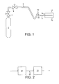
- FIG 2 there is shown schematically part of an automotive production line.
- the production line 20 includes a fusion welding station 22 and upline thereof a station 24 for cleaning the surface to be welded, the cleaning being performed by the method according to the invention.
- the station 24 may include the equipment shown in Figure 1.
- the production line may for example be for preparing car (automobile) bodies.
- the welding operation may be welding on the roof to the main part of the car body or any other part of the car.
Landscapes
- Engineering & Computer Science (AREA)
- Mechanical Engineering (AREA)
- Physics & Mathematics (AREA)
- Plasma & Fusion (AREA)
- Optics & Photonics (AREA)
- Arc Welding In General (AREA)
- Cleaning And De-Greasing Of Metallic Materials By Chemical Methods (AREA)
- Cleaning In General (AREA)
- Lining Or Joining Of Plastics Or The Like (AREA)
- Pharmaceuticals Containing Other Organic And Inorganic Compounds (AREA)
- Materials For Medical Uses (AREA)
Abstract
Description
- This invention relates to a method of preparing metal surfaces for welding, particularly their cleaning.
- Fusion welding is widely used throughout manufacturing industry to join pieces of metal together. Fusion welding processes such as Gas Metal Arc Welding (GMAW), Gas Tungsten Arc Welding (GTAW), and Plasma Arc Welding (PAW) have the advantage that they can be readily automated and can therefore be used on a production line. Other welding processes that are used include laser welding.
- Sometimes welds fail. One cause of failure is porosity. What typically happens is that the high temperature in the vicinity of the joint caused by the fusion welding process results in vaporisation and decomposition of contaminants such as oil present on the surfaces to be welded, hydrogen being formed as a decomposition product. Hydrogen has a high solubility in molten weld metal. Thus, if any hydrogen is formed by, say, decomposition of oil it is readily dissolved by the molten weld metal. As the weld metal subsequently falls in temperature so the solubility limit of hydrogen dramatically decreases. As a result, bubbles of hydrogen come out of the solution and form pores in the molten weld metal as it fuses. A visibly porous weld is thus formed. Such a weld is unacceptable as the pores may cause structural failure.
- Some metals, particularly aluminium, magnesium, and titanium, and their alloys, are more prone than others to porosity. Aluminium alloys, in particular, are being increasingly used in engineering because of their lightness. One example of the increasing use of aluminium alloys is in the manufacture of car bodies.
- Taking parts off a production line in order to clean them is not an acceptable solution to the problem of reducing incidences of porosity when welding.
- There is therefore a need for improved methods of weld preparation suitable for use on a production line which are able to reduce the incidence of porosity, particularly but not exclusively when welding parts of alloys based on aluminium, magnesium and titanium.
- US-A-6 213 849 relates to a method of preparing weld land areas of panels to be welded to each other. In the method carbon dioxide granules or pellets are blasted against the weld land areas. This procedure includes the step of injecting solid carbon dioxide pellets into a flow of warm air. The panels are then shot blasted. Once the panels have been prepared by the two blasting steps, they are positioned adjacent to one another and welded together.
- EP-A-372 902, US-A-5 836 809, US-A-5 725 154, US-A-5 616 067 and US-A-5 514 024 all relate to the formation of jets of gas carrying bodies of solid carbon dioxide.
- According to the present invention there is provided a method of cleaning metal surfaces to be welded together, the method comprising the steps of positioning the metal surfaces with a weld gap therebetween ready for welding, causing at least one jet carrying particles of solid carbon dioxide to come into contact with the surfaces and to enter the weld gap, and allowing the particles of solid carbon dioxide to sublime in the weld gap, wherein the jet carrying particles of solid carbon dioxide is formed by passing a stream of liquid carbon dioxide under pressure through a nozzle.
- The method according to the invention has several advantages.
- First, it can effectively remove oil and similar contaminants from the surfaces to be fusion welded together. Second, carbon dioxide itself does not have a deleterious effect on the weld. Third, any deposit of solid carbon dioxide on the surfaces or in the weld gap sublimes very quickly and does not generally necessitate any slowing of production. On the other hand, conventional organic solvents can leave residual traces that themselves will act as a precursor to hydrogen in the welding process. Fourth, it is simple to automate the method according to the invention and install it in on a production line. Fifth, and particularly importantly, the jet of carbon dioxide particles is effective in cleaning not only outer surfaces readily accessible on a production line, but also inner surfaces. Other advantages of the method according to the invention are disclosed below.
- The jet carrying particles of solid carbon dioxide is formed by causing a stream of liquid carbon dioxide under such a pressure through a nozzle that a mixture of gaseous carbon dioxide and particles of solid carbon dioxide are formed as a result. Suitable pressures for forming the mixture are well known in the art. For example, a pressure in the range of 20 to 50 bar is typically suitable. As a result discharge velocities in the range of 25 to 100 m/s can be achieved. The nozzle is preferably located close to the surfaces to be cleaned, say no more than 100 mm away. We have used distances in the range of 5 mm to 50 mm. The nozzle preferably has an on-off valve associated therewith, the valve able to be moved into its open position by activating a trigger. The nozzle preferably has an outlet of smaller internal diameter than the extent of the gap to be bridged by the weld.
- The source of liquid carbon dioxide is typically a thermally-insulated storage vessel containing the liquid carbon dioxide under pressure or a conventional compressed gas cylinder containing liquid carbon dioxide. Preferably, the nozzle is connected to the vessel by means of a flexible hose.
- The method according to the invention is particularly suitable for use in fusion welding together parts of an alloy based on aluminium, magnesium or titanium but can also be used to weld together parts made of a large number of other metals, including ferrous metal.
- The nozzle is preferably tracked over the entire line of the weld to be made at least once. Depending on the length of the weld, this may typically take up to one minute.
- The method according to the invention will now be described by way of example with reference to the accompanying drawings, in which:
- Figure 1 is a schematic diagram of apparatus for performing the method according to the invention;
- Figure 2 is a schematic side elevation of a production line according to the invention.
-
- The drawings are not to scale.
- Referring to Figure 1 of the drawings, a
cylindrical container 2 of liquid carbon dioxide having at its head a manually-operable cylinder valve 3 and manually-operablepressure regulating valve 4 is connected by aflexible hose 6, typically of stainless steel, to ajet nozzle 8 for forming a jet of gas carrying particles of solid carbon dioxide. In order to enable flow of the liquid carbon dioxide through thenozzle 8 to be established, the hose terminates in avalve 10 which is able to be activated by operation of atrigger 12 or the like. Normally thevalve 10 is in its closed position but depression of thetrigger 12 will cause thevalve 10 to open. If desired, thevalve 10 may be a solenoid valve. The tip of thenozzle 8 is pointed at theline 14 of a weld to be made between twoworkpieces - In operation, the cylinder valve 3 is opened and the
pressure regulating valve 4 is set to the desired downstream pressure. Thenozzle 8 is hand held with its tip close to and pointing at the line of the weld to be made. Thetrigger 12 is manually operable to open thevalve 10 and thereby to initiate flow of liquid carbon dioxide through thenozzle 8. The resulting pressure drop causes the liquid carbon dioxide to be converted into a jet of gas carrying solid particles of carbon dioxide 'snow'. The jet passes from the tip of thenozzle 8 and contacts the workpiece surfaces to be welded together. The momentum of the jet is such as to carry it into the narrow weld gap between theworkpieces nozzle 8 is manually moved along theentire line 14 of the weld once or twice. Solid carbon dioxide particles are deposited on the surfaces to be welded. Once all deposited carbon dioxide has sublimed, the weld may be made by a fusion or other welding method. Experiments that we have performed involving the deliberate introduction of oil contamination onto the surfaces to be welded have shown that the method according to the invention is particularly effective in removing the contamination as evidenced by the subsequent formation of sound welds on the clean workpieces. - It is believed that at least part of the cleaning effect of the jet of carbon dioxide results from the momentum with which it enters the weld gap. The momentum carries the carbon dioxide into the entire space to be occupied subsequently by the weld metal and enables particles of oil to be physically disengaged from the surfaces to be welded together and carried off with the carbon dioxide. Solid particles of carbon dioxide have of course a temperature well below ambient and it is further believed that the low temperature may contribute to the efficacy of the method according to the invention. Further, sublimation of the snow takes place in the weld gap with a large increase in volume, and this expansion may also contribute to the effectiveness of the method according to the invention. The relative importance of the various factors discussed in this paragraph is not fully understood and the invention is not to be limited to any theoretical explanation of the how it works.
- The method according to the invention is further illustrated by the following example.
- Experiments were performed on two pairs of aluminium test pieces each 300 mm long, 50 mm wide, and 3 mm thick and each deliberately contaminated with oil. A welded lap joint was made between both pairs of test pieces. One pair was subjected to the cleaning method according to the invention. A nozzle having a diameter of 1.6 mm at its exit was formed to use the jet of carbon dioxide. (If desired, a larger diameter nozzle may be used instead, for example one having a diameter of 3.2 mm.) The tip of the nozzle was held 5 mm away from the line of the weld. The carbon dioxide was supplied at a rate of 1 kg/min for up to 1 minute. (Other spray rates in the range of 0.5 to 2 kg/min could have been used instead.) A carbon dioxide supply pressure in the range of 20 to 50 bar was selected. The cleaned test pieces were allowed to stand for 5 minutes. During that time the surfaces were wiped with a clean cloth. This ensured removal of any residual particles and disengaged from the surfaces by the action of the carbon dioxide but still in contact therewith. The lap joint was then made as a 3 mm fillet weld by a GMAW welding method. The weld was inspected visually. No defects were found. The weld was then cut open, polished, and etched and viewed under a microscope. Again, no defects were found.
- The procedure was repeated on the other pair of test pieces with the exception that they were not cleaned. The resulting weld was found to be porous.
- In Figure 2 there is shown schematically part of an automotive production line. The
production line 20 includes afusion welding station 22 and upline thereof astation 24 for cleaning the surface to be welded, the cleaning being performed by the method according to the invention. Thestation 24 may include the equipment shown in Figure 1. The production line may for example be for preparing car (automobile) bodies. The welding operation may be welding on the roof to the main part of the car body or any other part of the car.
Claims (7)
- A method of cleaning metal surfaces to be welded together, the method comprising the steps of positioning the metal surfaces with a weld gap therebetween ready for welding, causing at least one jet carrying particles of solid carbon dioxide to come into contact with the surfaces and to enter the weld gap, and allowing the particles of solid carbon dioxide to sublime in the weld gap, wherein the jet carrying particles of solid carbon dioxide is formed by passing a stream of liquid carbon dioxide under pressure through a nozzle.
- A method as claimed in Claim 1, wherein the pressure is in the range of 20 to 50 bar.
- A method as claimed in Claim 1 or Claim 2, in which the internal diameter of the outlet of the nozzle is less than the extent of the gap between the surfaces to be welded.
- A method as claimed in any one of the preceding claims, wherein the nozzle is located less than 100 mm away from the surfaces to be welded together.
- A method as claimed in Claim 4, wherein the distance is in the range of 5 mm to 50 mm.
- A method as claimed in any one of the preceding claims, wherein the surfaces are of aluminium, an aluminium-based alloy, a magnesium based alloy, or a titanium-bases alloy.
- A method as claimed in any one of the preceding claims, in which the jet is caused to move at least once along the entire line of the weld to be made.
Applications Claiming Priority (2)
| Application Number | Priority Date | Filing Date | Title |
|---|---|---|---|
| GB0129353 | 2001-12-07 | ||
| GBGB0129353.9A GB0129353D0 (en) | 2001-12-07 | 2001-12-07 | Weld preparation method |
Publications (2)
| Publication Number | Publication Date |
|---|---|
| EP1319460A1 true EP1319460A1 (en) | 2003-06-18 |
| EP1319460B1 EP1319460B1 (en) | 2008-02-13 |
Family
ID=9927220
Family Applications (1)
| Application Number | Title | Priority Date | Filing Date |
|---|---|---|---|
| EP02258343A Expired - Lifetime EP1319460B1 (en) | 2001-12-07 | 2002-12-03 | Weld preparation method |
Country Status (8)
| Country | Link |
|---|---|
| US (1) | US6852011B2 (en) |
| EP (1) | EP1319460B1 (en) |
| AT (1) | ATE385871T1 (en) |
| CA (1) | CA2413511C (en) |
| DE (1) | DE60224977T2 (en) |
| ES (1) | ES2301609T3 (en) |
| GB (1) | GB0129353D0 (en) |
| ZA (1) | ZA200209652B (en) |
Cited By (4)
| Publication number | Priority date | Publication date | Assignee | Title |
|---|---|---|---|---|
| ES2277514A1 (en) * | 2005-04-20 | 2007-07-01 | Binzel Soldadura, S.L. | Arc welding torch with pressurized cryogenic gas cleaning device, includes carbon dioxide bottle, cryogenic solenoid valve and tube for supplying stream of liquid carbon dioxide |
| WO2008141156A1 (en) * | 2007-05-12 | 2008-11-20 | Honeywell International Inc. | Button attachment method for saw torque sensor |
| EP2014401A1 (en) | 2007-07-10 | 2009-01-14 | Linde AG | Method and device for welding workpieces |
| WO2012089228A1 (en) * | 2010-12-30 | 2012-07-05 | Robert Bosch G.M.B.H. | Method and device for processing a metal ring, an annular metal band thus formed and a drive belt in which the annular metal band is used |
Families Citing this family (5)
| Publication number | Priority date | Publication date | Assignee | Title |
|---|---|---|---|---|
| US8292698B1 (en) * | 2007-03-30 | 2012-10-23 | Lam Research Corporation | On-line chamber cleaning using dry ice blasting |
| US8257147B2 (en) * | 2008-03-10 | 2012-09-04 | Regency Technologies, Llc | Method and apparatus for jet-assisted drilling or cutting |
| US20130105561A1 (en) * | 2011-11-01 | 2013-05-02 | Amee Bay, Llc | Dry ice cleaning of metal surfaces to improve welding characteristics |
| CN102873428A (en) * | 2012-09-13 | 2013-01-16 | 林淑琴 | Portable welding gun |
| DE102016125599A1 (en) * | 2016-12-23 | 2018-06-28 | Newfrey Llc | Method and device for joining joining elements to components |
Citations (7)
| Publication number | Priority date | Publication date | Assignee | Title |
|---|---|---|---|---|
| US4038786A (en) * | 1974-09-27 | 1977-08-02 | Lockheed Aircraft Corporation | Sandblasting with pellets of material capable of sublimation |
| JPS5728694A (en) * | 1980-07-30 | 1982-02-16 | Ishii Tekkosho:Kk | Method for blast cleaning of welded groove part |
| EP0689897A1 (en) * | 1994-07-01 | 1996-01-03 | Kvaerner Masa-Yards Oy | Method for welding aluminium plates |
| US5525093A (en) * | 1993-04-27 | 1996-06-11 | Westinghouse Electric Corporation | Cleaning method and apparatus |
| US5725154A (en) * | 1995-08-18 | 1998-03-10 | Jackson; David P. | Dense fluid spray cleaning method and apparatus |
| US6213849B1 (en) * | 1998-08-18 | 2001-04-10 | Lockheed Martin Corporation | Automated barrel panel transfer and processing system |
| EP1151820A2 (en) * | 2000-05-03 | 2001-11-07 | The BOC Group plc | Improvements in thermal welding |
Family Cites Families (8)
| Publication number | Priority date | Publication date | Assignee | Title |
|---|---|---|---|---|
| US5071486A (en) * | 1986-02-06 | 1991-12-10 | University Of Dayton | Process for removing protective coatings and bonding layers from metal parts |
| US4962891A (en) | 1988-12-06 | 1990-10-16 | The Boc Group, Inc. | Apparatus for removing small particles from a substrate |
| US5599223A (en) * | 1991-04-10 | 1997-02-04 | Mains Jr.; Gilbert L. | Method for material removal |
| US5108512A (en) * | 1991-09-16 | 1992-04-28 | Hemlock Semiconductor Corporation | Cleaning of CVD reactor used in the production of polycrystalline silicon by impacting with carbon dioxide pellets |
| US5514024A (en) | 1993-11-08 | 1996-05-07 | Ford Motor Company | Nozzle for enhanced mixing in CO2 cleaning system |
| US5447577A (en) * | 1994-10-24 | 1995-09-05 | Ford Motor Company | Carbon dioxide-based fluxing media for non-VOC, no-clean soldering |
| US5616067A (en) | 1996-01-16 | 1997-04-01 | Ford Motor Company | CO2 nozzle and method for cleaning pressure-sensitive surfaces |
| US5836809A (en) | 1996-10-07 | 1998-11-17 | Eco-Snow Systems, Inc. | Apparatus and method for cleaning large glass plates using linear arrays of carbon dioxide (CO2) jet spray nozzles |
-
2001
- 2001-12-07 GB GBGB0129353.9A patent/GB0129353D0/en not_active Ceased
-
2002
- 2002-11-27 ZA ZA200209652A patent/ZA200209652B/en unknown
- 2002-12-03 EP EP02258343A patent/EP1319460B1/en not_active Expired - Lifetime
- 2002-12-03 DE DE60224977T patent/DE60224977T2/en not_active Expired - Lifetime
- 2002-12-03 US US10/308,774 patent/US6852011B2/en not_active Expired - Fee Related
- 2002-12-03 AT AT02258343T patent/ATE385871T1/en active
- 2002-12-03 ES ES02258343T patent/ES2301609T3/en not_active Expired - Lifetime
- 2002-12-04 CA CA002413511A patent/CA2413511C/en not_active Expired - Fee Related
Patent Citations (7)
| Publication number | Priority date | Publication date | Assignee | Title |
|---|---|---|---|---|
| US4038786A (en) * | 1974-09-27 | 1977-08-02 | Lockheed Aircraft Corporation | Sandblasting with pellets of material capable of sublimation |
| JPS5728694A (en) * | 1980-07-30 | 1982-02-16 | Ishii Tekkosho:Kk | Method for blast cleaning of welded groove part |
| US5525093A (en) * | 1993-04-27 | 1996-06-11 | Westinghouse Electric Corporation | Cleaning method and apparatus |
| EP0689897A1 (en) * | 1994-07-01 | 1996-01-03 | Kvaerner Masa-Yards Oy | Method for welding aluminium plates |
| US5725154A (en) * | 1995-08-18 | 1998-03-10 | Jackson; David P. | Dense fluid spray cleaning method and apparatus |
| US6213849B1 (en) * | 1998-08-18 | 2001-04-10 | Lockheed Martin Corporation | Automated barrel panel transfer and processing system |
| EP1151820A2 (en) * | 2000-05-03 | 2001-11-07 | The BOC Group plc | Improvements in thermal welding |
Non-Patent Citations (1)
| Title |
|---|
| PATENT ABSTRACTS OF JAPAN vol. 006, no. 093 (M - 133) 29 May 1982 (1982-05-29) * |
Cited By (6)
| Publication number | Priority date | Publication date | Assignee | Title |
|---|---|---|---|---|
| ES2277514A1 (en) * | 2005-04-20 | 2007-07-01 | Binzel Soldadura, S.L. | Arc welding torch with pressurized cryogenic gas cleaning device, includes carbon dioxide bottle, cryogenic solenoid valve and tube for supplying stream of liquid carbon dioxide |
| ES2277514B1 (en) * | 2005-04-20 | 2008-05-16 | Binzel Soldadura, S.L. | ARCH WELDING TORCH WITH CLEANING DEVICE INCORPORATED BY HIGH PRESSURE CRIOGENIC GAS. |
| WO2008141156A1 (en) * | 2007-05-12 | 2008-11-20 | Honeywell International Inc. | Button attachment method for saw torque sensor |
| US8071907B2 (en) | 2007-05-12 | 2011-12-06 | Honeywell International Inc. | Button attachment method for saw torque sensor |
| EP2014401A1 (en) | 2007-07-10 | 2009-01-14 | Linde AG | Method and device for welding workpieces |
| WO2012089228A1 (en) * | 2010-12-30 | 2012-07-05 | Robert Bosch G.M.B.H. | Method and device for processing a metal ring, an annular metal band thus formed and a drive belt in which the annular metal band is used |
Also Published As
| Publication number | Publication date |
|---|---|
| GB0129353D0 (en) | 2002-01-30 |
| ZA200209652B (en) | 2003-06-10 |
| EP1319460B1 (en) | 2008-02-13 |
| CA2413511A1 (en) | 2003-06-07 |
| DE60224977D1 (en) | 2008-03-27 |
| DE60224977T2 (en) | 2009-02-05 |
| ATE385871T1 (en) | 2008-03-15 |
| ES2301609T3 (en) | 2008-07-01 |
| US20030119423A1 (en) | 2003-06-26 |
| US6852011B2 (en) | 2005-02-08 |
| CA2413511C (en) | 2009-11-17 |
Similar Documents
| Publication | Publication Date | Title |
|---|---|---|
| EP2014401B1 (en) | Method and device for welding workpieces | |
| EP1319460B1 (en) | Weld preparation method | |
| EP1092497A1 (en) | Method for repairing spray-formed steel tooling | |
| JPH06297331A (en) | Apparatus and method for blasting metal surfaces | |
| EP1151820B1 (en) | Improved friction stir weldin method using a cryogen flow | |
| MXPA05013002A (en) | Superalloy repair using cold spray. | |
| EP1356890B1 (en) | Method of electric arc or laser welding of metal workpieces assisted by cryogen flow | |
| US20080115809A1 (en) | Method for cleaning of welding torches | |
| US4306137A (en) | Method and apparatus for conducting smut-free stud welding | |
| US3033133A (en) | Powder washing apparatus | |
| JP2007534496A (en) | Cleaning method and apparatus for welding burner using CO2 dry ice | |
| EP2678135B1 (en) | Equipment for cold-cleaning of welding torches | |
| US20070045238A1 (en) | Method of welding material with reduced porosity | |
| JP5723212B2 (en) | Cleaning device, cleaning method and temper rolling mill | |
| JP2007537884A (en) | Method and apparatus for cleaning electrode or cap used for resistance spot welding, and resistance spot welding apparatus | |
| JP2009541067A (en) | Apparatus and method for processing a solid material using a water jet | |
| JPH06126621A (en) | Method for manufacturing defect-free hot rolled coil | |
| US4486644A (en) | Method for conducting smut-free welding | |
| US10759395B2 (en) | Method for restoring at least one portion of a body of a valuable historic vehicle | |
| RU2332285C2 (en) | Method of welding in protective gas with gas-dynamic removal of contamination layer from welding zone | |
| JPS5770086A (en) | Build up welding method of butted member | |
| JPH04275875A (en) | Surface layer treatment device for surface treated steel sheet and manufacturing equipment of electro-resistance-welded steel pipe | |
| Brosilow | Pushing GMAW to the Limit | |
| JPH04231112A (en) | Equipment for manufacturing electric resistance welded steel tube | |
| JPH0885059A (en) | How to remove open flaws |
Legal Events
| Date | Code | Title | Description |
|---|---|---|---|
| PUAI | Public reference made under article 153(3) epc to a published international application that has entered the european phase |
Free format text: ORIGINAL CODE: 0009012 |
|
| AK | Designated contracting states |
Designated state(s): AT BE BG CH CY CZ DE DK EE ES FI FR GB GR IE IT LI LU MC NL PT SE SI SK TR |
|
| AX | Request for extension of the european patent |
Extension state: AL LT LV MK RO |
|
| RIN1 | Information on inventor provided before grant (corrected) |
Inventor name: VELDSMAN, WALTER MARK Inventor name: GABZDL, JACEK TADEUSZ |
|
| RIN1 | Information on inventor provided before grant (corrected) |
Inventor name: GABZDYL, JACEK TADEUSZ Inventor name: VELDSMAN, WALTER MARK |
|
| 17P | Request for examination filed |
Effective date: 20031111 |
|
| AKX | Designation fees paid |
Designated state(s): AT BE BG CH CY CZ DE DK EE ES FI FR GB GR IE IT LI LU MC NL PT SE SI SK TR |
|
| 17Q | First examination report despatched |
Effective date: 20050204 |
|
| GRAP | Despatch of communication of intention to grant a patent |
Free format text: ORIGINAL CODE: EPIDOSNIGR1 |
|
| GRAS | Grant fee paid |
Free format text: ORIGINAL CODE: EPIDOSNIGR3 |
|
| GRAA | (expected) grant |
Free format text: ORIGINAL CODE: 0009210 |
|
| AK | Designated contracting states |
Kind code of ref document: B1 Designated state(s): AT BE BG CH CY CZ DE DK EE ES FI FR GB GR IE IT LI LU MC NL PT SE SI SK TR |
|
| REG | Reference to a national code |
Ref country code: GB Ref legal event code: FG4D |
|
| REG | Reference to a national code |
Ref country code: CH Ref legal event code: EP |
|
| REG | Reference to a national code |
Ref country code: IE Ref legal event code: FG4D |
|
| REF | Corresponds to: |
Ref document number: 60224977 Country of ref document: DE Date of ref document: 20080327 Kind code of ref document: P |
|
| REG | Reference to a national code |
Ref country code: SE Ref legal event code: TRGR |
|
| REG | Reference to a national code |
Ref country code: CH Ref legal event code: NV Representative=s name: RIEDERER HASLER & PARTNER PATENTANWAELTE AG |
|
| REG | Reference to a national code |
Ref country code: ES Ref legal event code: FG2A Ref document number: 2301609 Country of ref document: ES Kind code of ref document: T3 |
|
| PG25 | Lapsed in a contracting state [announced via postgrant information from national office to epo] |
Ref country code: FI Free format text: LAPSE BECAUSE OF FAILURE TO SUBMIT A TRANSLATION OF THE DESCRIPTION OR TO PAY THE FEE WITHIN THE PRESCRIBED TIME-LIMIT Effective date: 20080213 |
|
| PG25 | Lapsed in a contracting state [announced via postgrant information from national office to epo] |
Ref country code: SI Free format text: LAPSE BECAUSE OF FAILURE TO SUBMIT A TRANSLATION OF THE DESCRIPTION OR TO PAY THE FEE WITHIN THE PRESCRIBED TIME-LIMIT Effective date: 20080213 |
|
| ET | Fr: translation filed | ||
| PG25 | Lapsed in a contracting state [announced via postgrant information from national office to epo] |
Ref country code: DK Free format text: LAPSE BECAUSE OF FAILURE TO SUBMIT A TRANSLATION OF THE DESCRIPTION OR TO PAY THE FEE WITHIN THE PRESCRIBED TIME-LIMIT Effective date: 20080213 Ref country code: PT Free format text: LAPSE BECAUSE OF FAILURE TO SUBMIT A TRANSLATION OF THE DESCRIPTION OR TO PAY THE FEE WITHIN THE PRESCRIBED TIME-LIMIT Effective date: 20080714 |
|
| RAP2 | Party data changed (patent owner data changed or rights of a patent transferred) |
Owner name: THE BOC GROUP LIMITED |
|
| REG | Reference to a national code |
Ref country code: CH Ref legal event code: PFA Owner name: THE BOC GROUP LIMITED Free format text: THE BOC GROUP PLC#CHERTSEY ROAD#WINDLESHAM SURREY GU20 6HJ (GB) -TRANSFER TO- THE BOC GROUP LIMITED#THE PRIESTLEY CENTRE 10 PRIESTLEY ROAD THE SURREY RESEARCH PARK#GUILDFORD SURREY GU2 7XY (GB) |
|
| PLBE | No opposition filed within time limit |
Free format text: ORIGINAL CODE: 0009261 |
|
| STAA | Information on the status of an ep patent application or granted ep patent |
Free format text: STATUS: NO OPPOSITION FILED WITHIN TIME LIMIT |
|
| NLT2 | Nl: modifications (of names), taken from the european patent patent bulletin |
Owner name: THE BOC GROUP LIMITED Effective date: 20081112 |
|
| 26N | No opposition filed |
Effective date: 20081114 |
|
| NLT1 | Nl: modifications of names registered in virtue of documents presented to the patent office pursuant to art. 16 a, paragraph 1 |
Owner name: THE BOC GROUP LIMITED |
|
| PG25 | Lapsed in a contracting state [announced via postgrant information from national office to epo] |
Ref country code: EE Free format text: LAPSE BECAUSE OF FAILURE TO SUBMIT A TRANSLATION OF THE DESCRIPTION OR TO PAY THE FEE WITHIN THE PRESCRIBED TIME-LIMIT Effective date: 20080213 Ref country code: BG Free format text: LAPSE BECAUSE OF FAILURE TO SUBMIT A TRANSLATION OF THE DESCRIPTION OR TO PAY THE FEE WITHIN THE PRESCRIBED TIME-LIMIT Effective date: 20080513 |
|
| PG25 | Lapsed in a contracting state [announced via postgrant information from national office to epo] |
Ref country code: CY Free format text: LAPSE BECAUSE OF FAILURE TO SUBMIT A TRANSLATION OF THE DESCRIPTION OR TO PAY THE FEE WITHIN THE PRESCRIBED TIME-LIMIT Effective date: 20080213 Ref country code: MC Free format text: LAPSE BECAUSE OF NON-PAYMENT OF DUE FEES Effective date: 20081231 |
|
| PG25 | Lapsed in a contracting state [announced via postgrant information from national office to epo] |
Ref country code: IE Free format text: LAPSE BECAUSE OF NON-PAYMENT OF DUE FEES Effective date: 20081203 |
|
| PG25 | Lapsed in a contracting state [announced via postgrant information from national office to epo] |
Ref country code: LU Free format text: LAPSE BECAUSE OF NON-PAYMENT OF DUE FEES Effective date: 20081203 |
|
| PG25 | Lapsed in a contracting state [announced via postgrant information from national office to epo] |
Ref country code: TR Free format text: LAPSE BECAUSE OF FAILURE TO SUBMIT A TRANSLATION OF THE DESCRIPTION OR TO PAY THE FEE WITHIN THE PRESCRIBED TIME-LIMIT Effective date: 20080213 |
|
| PG25 | Lapsed in a contracting state [announced via postgrant information from national office to epo] |
Ref country code: GR Free format text: LAPSE BECAUSE OF FAILURE TO SUBMIT A TRANSLATION OF THE DESCRIPTION OR TO PAY THE FEE WITHIN THE PRESCRIBED TIME-LIMIT Effective date: 20080514 |
|
| PGFP | Annual fee paid to national office [announced via postgrant information from national office to epo] |
Ref country code: NL Payment date: 20101210 Year of fee payment: 9 |
|
| PGFP | Annual fee paid to national office [announced via postgrant information from national office to epo] |
Ref country code: BE Payment date: 20110222 Year of fee payment: 9 |
|
| BERE | Be: lapsed |
Owner name: THE BOC GROUP P.L.C. Effective date: 20111231 |
|
| REG | Reference to a national code |
Ref country code: NL Ref legal event code: V1 Effective date: 20120701 |
|
| PG25 | Lapsed in a contracting state [announced via postgrant information from national office to epo] |
Ref country code: BE Free format text: LAPSE BECAUSE OF NON-PAYMENT OF DUE FEES Effective date: 20111231 |
|
| PG25 | Lapsed in a contracting state [announced via postgrant information from national office to epo] |
Ref country code: NL Free format text: LAPSE BECAUSE OF NON-PAYMENT OF DUE FEES Effective date: 20120701 |
|
| PGFP | Annual fee paid to national office [announced via postgrant information from national office to epo] |
Ref country code: IT Payment date: 20121220 Year of fee payment: 11 Ref country code: SK Payment date: 20121123 Year of fee payment: 11 |
|
| PGFP | Annual fee paid to national office [announced via postgrant information from national office to epo] |
Ref country code: AT Payment date: 20121127 Year of fee payment: 11 |
|
| REG | Reference to a national code |
Ref country code: AT Ref legal event code: MM01 Ref document number: 385871 Country of ref document: AT Kind code of ref document: T Effective date: 20131203 |
|
| REG | Reference to a national code |
Ref country code: SK Ref legal event code: MM4A Ref document number: E 3453 Country of ref document: SK Effective date: 20131203 |
|
| PG25 | Lapsed in a contracting state [announced via postgrant information from national office to epo] |
Ref country code: SK Free format text: LAPSE BECAUSE OF NON-PAYMENT OF DUE FEES Effective date: 20131203 Ref country code: AT Free format text: LAPSE BECAUSE OF NON-PAYMENT OF DUE FEES Effective date: 20131203 |
|
| PGFP | Annual fee paid to national office [announced via postgrant information from national office to epo] |
Ref country code: CH Payment date: 20141212 Year of fee payment: 13 Ref country code: SE Payment date: 20141211 Year of fee payment: 13 Ref country code: DE Payment date: 20141125 Year of fee payment: 13 Ref country code: ES Payment date: 20141111 Year of fee payment: 13 Ref country code: CZ Payment date: 20141113 Year of fee payment: 13 |
|
| PGFP | Annual fee paid to national office [announced via postgrant information from national office to epo] |
Ref country code: FR Payment date: 20141208 Year of fee payment: 13 |
|
| PG25 | Lapsed in a contracting state [announced via postgrant information from national office to epo] |
Ref country code: IT Free format text: LAPSE BECAUSE OF NON-PAYMENT OF DUE FEES Effective date: 20131231 |
|
| PG25 | Lapsed in a contracting state [announced via postgrant information from national office to epo] |
Ref country code: IT Free format text: LAPSE BECAUSE OF NON-PAYMENT OF DUE FEES Effective date: 20131203 |
|
| REG | Reference to a national code |
Ref country code: DE Ref legal event code: R119 Ref document number: 60224977 Country of ref document: DE |
|
| PG25 | Lapsed in a contracting state [announced via postgrant information from national office to epo] |
Ref country code: CZ Free format text: LAPSE BECAUSE OF NON-PAYMENT OF DUE FEES Effective date: 20151203 |
|
| REG | Reference to a national code |
Ref country code: CH Ref legal event code: PL |
|
| REG | Reference to a national code |
Ref country code: SE Ref legal event code: EUG |
|
| PG25 | Lapsed in a contracting state [announced via postgrant information from national office to epo] |
Ref country code: SE Free format text: LAPSE BECAUSE OF NON-PAYMENT OF DUE FEES Effective date: 20151204 |
|
| REG | Reference to a national code |
Ref country code: FR Ref legal event code: ST Effective date: 20160831 |
|
| PG25 | Lapsed in a contracting state [announced via postgrant information from national office to epo] |
Ref country code: CH Free format text: LAPSE BECAUSE OF NON-PAYMENT OF DUE FEES Effective date: 20151231 Ref country code: DE Free format text: LAPSE BECAUSE OF NON-PAYMENT OF DUE FEES Effective date: 20160701 Ref country code: LI Free format text: LAPSE BECAUSE OF NON-PAYMENT OF DUE FEES Effective date: 20151231 |
|
| PG25 | Lapsed in a contracting state [announced via postgrant information from national office to epo] |
Ref country code: FR Free format text: LAPSE BECAUSE OF NON-PAYMENT OF DUE FEES Effective date: 20151231 |
|
| REG | Reference to a national code |
Ref country code: ES Ref legal event code: FD2A Effective date: 20170201 |
|
| PG25 | Lapsed in a contracting state [announced via postgrant information from national office to epo] |
Ref country code: ES Free format text: LAPSE BECAUSE OF NON-PAYMENT OF DUE FEES Effective date: 20151204 |
|
| PGFP | Annual fee paid to national office [announced via postgrant information from national office to epo] |
Ref country code: GB Payment date: 20181128 Year of fee payment: 17 |
|
| GBPC | Gb: european patent ceased through non-payment of renewal fee |
Effective date: 20191203 |
|
| PG25 | Lapsed in a contracting state [announced via postgrant information from national office to epo] |
Ref country code: GB Free format text: LAPSE BECAUSE OF NON-PAYMENT OF DUE FEES Effective date: 20191203 |