EP1319446A2 - Suction nozzle - Google Patents
Suction nozzle Download PDFInfo
- Publication number
- EP1319446A2 EP1319446A2 EP20020258620 EP02258620A EP1319446A2 EP 1319446 A2 EP1319446 A2 EP 1319446A2 EP 20020258620 EP20020258620 EP 20020258620 EP 02258620 A EP02258620 A EP 02258620A EP 1319446 A2 EP1319446 A2 EP 1319446A2
- Authority
- EP
- European Patent Office
- Prior art keywords
- nozzle
- coating
- substrate
- suction nozzle
- cleaning liquid
- Prior art date
- Legal status (The legal status is an assumption and is not a legal conclusion. Google has not performed a legal analysis and makes no representation as to the accuracy of the status listed.)
- Withdrawn
Links
- 239000007788 liquid Substances 0.000 claims abstract description 33
- 239000000758 substrate Substances 0.000 claims abstract description 26
- 238000004140 cleaning Methods 0.000 claims abstract description 22
- 239000011324 bead Substances 0.000 claims abstract description 16
- 239000011248 coating agent Substances 0.000 claims abstract description 16
- 238000000576 coating method Methods 0.000 claims abstract description 16
- 230000001133 acceleration Effects 0.000 claims abstract description 4
- 230000009977 dual effect Effects 0.000 claims abstract description 4
- 239000011247 coating layer Substances 0.000 claims abstract 2
- 238000000034 method Methods 0.000 description 10
- 238000007766 curtain coating Methods 0.000 description 7
- 238000004519 manufacturing process Methods 0.000 description 4
- 239000008199 coating composition Substances 0.000 description 3
- 239000000463 material Substances 0.000 description 3
- 230000000630 rising effect Effects 0.000 description 3
- 239000000203 mixture Substances 0.000 description 2
- 230000002000 scavenging effect Effects 0.000 description 2
- 239000000243 solution Substances 0.000 description 2
- 238000009736 wetting Methods 0.000 description 2
- 230000006978 adaptation Effects 0.000 description 1
- 238000010790 dilution Methods 0.000 description 1
- 239000012895 dilution Substances 0.000 description 1
- 238000001035 drying Methods 0.000 description 1
- 239000000945 filler Substances 0.000 description 1
- 239000012530 fluid Substances 0.000 description 1
- 239000002904 solvent Substances 0.000 description 1
- 238000011144 upstream manufacturing Methods 0.000 description 1
- XLYOFNOQVPJJNP-UHFFFAOYSA-N water Substances O XLYOFNOQVPJJNP-UHFFFAOYSA-N 0.000 description 1
Images

Classifications
-
- B—PERFORMING OPERATIONS; TRANSPORTING
- B05—SPRAYING OR ATOMISING IN GENERAL; APPLYING FLUENT MATERIALS TO SURFACES, IN GENERAL
- B05C—APPARATUS FOR APPLYING FLUENT MATERIALS TO SURFACES, IN GENERAL
- B05C11/00—Component parts, details or accessories not specifically provided for in groups B05C1/00 - B05C9/00
- B05C11/10—Storage, supply or control of liquid or other fluent material; Recovery of excess liquid or other fluent material
- B05C11/1039—Recovery of excess liquid or other fluent material; Controlling means therefor
-
- B—PERFORMING OPERATIONS; TRANSPORTING
- B05—SPRAYING OR ATOMISING IN GENERAL; APPLYING FLUENT MATERIALS TO SURFACES, IN GENERAL
- B05C—APPARATUS FOR APPLYING FLUENT MATERIALS TO SURFACES, IN GENERAL
- B05C5/00—Apparatus in which liquid or other fluent material is projected, poured or allowed to flow on to the surface of the work
- B05C5/005—Curtain coaters
Definitions
- the present invention relates to a suction nozzle and method for removing lateral edge bead portions of a coated layer of a continuously moving substrate with one or more simultaneously applied layers of liquid coating materials, and, more particularly to a suction nozzle and a method for removing said lateral edge bead portions under very high velocity from the substrate.
- curtain coating methods and apparatus are widely known and used.
- a continuous web or sheets are continuously moved below a coating hopper.
- One or more liquid compositions are provided from a hopper arrangement in the form of a liquid curtain.
- liquid compositions are used of relatively low viscosity, generally less than about 150 cP (centipoise), most in the range from about 5 to about 100 cP.
- the coated layer often has a tendency to rise along both lateral edges of the web to form edge bead portions due to the surface tension of the coating composition.
- a further problem is that the edges may be luted which leads to problems in use of the coated substrate.
- the coated layer can not be dried uniformly at the edge bead portions. Therefore, the edge bead portions should be removed before drying of the substrate.
- a suction nozzle and a method for applying a coating composition to an elongated flexible web which is continuously moving wherein the suction nozzle has a dual pipe structure with a cleaning liquid jetting outlet and a liquid sucking inlet at its end, in which the jetting nozzle is offset from the longitudinal axis of the nozzle and forms an angle of 30 degrees to 85 degrees with respect to the longitudinal axis of the nozzle, and the sucking inlet is positioned on the longitudinal axis.
- angles smaller than 30 degrees lead to the liquid flowing to the rear side of the substrate and an angle larger than 90 degrees leads to the sucking inlet not being sufficiently cleaned.
- the removal of rising coated layer at the edge bead portions of the moving web may be improved which apparently allows a better coating quality of the moving web.
- a suction nozzle in which a means to get a longer distance of acceleration is provided.
- the problems are also solved by providing a method for removing lateral edge bead portions of a coated layer of a higher speed continuously moving substrate like a paper web by sucking air into the nozzle opening over a long accelerating way wherein a substrate is moved below a hopper arrangement providing one or more liquid coating materials in the form of a free-falling curtain impinging the substrate at a dynamic wetting line, wherein the dynamic wetting line of the coating curtain on the substrate or web is oriented generally perpendicular to the moving direction of the substrate or web.
- the nozzle is able to thoroughly remove the elevated coated layer at edge bead portions at the high speed of the moving substrate.
- the nozzle end in the area of its opening is provided such that ingressing air is accelerated in speed.
- the end is relatively flat to elongate the distance of acceleration.
- the air ingress angle relative to the plane of the substrate to be coated is small, especially smaller than 30 degrees, more preferably smaller than 20 degrees, most preferably between 0 and about 10 degrees.
- the moving speed of the substrate is above 1000 m/min, preferably in a range of about 20 m/s to about 40 m/s.
- the air speed at air inlet for ingressing air of suction or vacuum means or suction nozzle exceeds double the speed value of the moving substrate, most preferred about 200 m/s to about 250 m/s.
- the nozzle comprises an inlet for scavenging fluid or cleaning liquids running through the nozzle opening.
- the scavenging or cleaning liquids are supplied from a cleaning liquid supply support through a conduit in the nozzle.
- the outlet for that cleaning liquid runs around the nozzle opening, preferably inside the nozzle opening.
- the gap to supply the cleaning liquid in the area of the nozzle opening measures preferably 0.5 mm, more preferably 0.2 mm. It is preferred to have a small gap to diffuse the cleaning liquid over the whole edge bead portions.
- the cleaning liquid is supplied at 250 ml/min or 151/h.
- the suction nozzle comprises a pressure gauging means in a vacuum line to control the amount of vacuum supplied.
- a suction nozzle according to the invention is preferably provided with a ring which may preferably be adapted to permit a free flow of ingressing air and detaching coating material.
- Figure 1 shows a suction nozzle arrangement over a substrate having coated layer risen along both lateral edges of the substrate or web formed as edge bead portions as known from the prior art.
- a conventional suction nozzle 10 is of a dual part structure having a liquid jetting outlet 12 and a cleaning liquid suction inlet 14 at the end.
- the jetting outlet 12 is offset of the longitudinal axis 16 of the nozzle.
- the sucking inlet 14 is located on this axis.
- a cleaning solution supply port 18 to which water or solvent is supplied.
- the cleaning solution runs through a groove 20, which is straight.
- the angle between the jetting outlet 12 and the longitudinal axis of the nozzle which is the angle ⁇ in figure 1 may be in the prior art in the range of 30 to 85 degrees.
- the nozzle is moved along an edge bead portion 22 of the coated layer 24 provided on the substrate or web 26.
- an evacuating port 28 which is connected to a vacuum pump, not shown in figure 1, the lateral edge bead portions are removed after dilution together with the cleaning liquid from the coated layer.
- the cleaning liquid runs, for the purpose of this application, downstream the nozzle and the removed lateral edge bead portions together with the cleaning liquid from the coated layer run upstream for the purpose of this application.
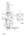
- a suction nozzle or vacuum means according to the present invention is shown in a partly cross sectional view in figure 2. Parts being the same or similar to those described above depicted by the same reference number for the ease of understanding.
- the cleaning liquid supply port 18 is continued into the nozzle body 30.
- a liquid supply line 32 is provided essentially perpendicular to the cleaning liquid supply port 18 and is provided as a groove in the front part 34 of the nozzle.
- the front part 34 to the nozzle comprises an inner and an outer part 36, 38, where the inner part is spaced a distance from the outer part in the end area of the front part of the nozzle.
- the gap is formed as a ring and ends in the cleaning liquid jetting outlet 12. It is provided surrounding the cleaning liquid sucking inlet 14 at the end of the nozzle.
- the gap g preferably measures about 0.5 to 0.2 mm.
- the angle ⁇ between the outer surface of the opening end of the nozzle and the surface of the coated substrate is small and may be in the range of 30 degrees, preferably 20 degrees, more preferably 0 to about 10 degrees.
- removal of edge bead portions is possible with very high speeds of moving substrate 26 in the curtain coating process.
- the drawbacks of luted edges covered with rising coated layer may be overcome.
- the cleaning liquid jetting outlet 12 surrounding the cleaning liquid sucking inlet 14 at the inside of the nozzle the nozzle maintains clean at all times such that the coating compositions will not solidify or accumulate inside the nozzle such that the nozzle may be operated for long periods of time.
- the flow through the passageway 40 running through the nozzle and the evacuating port 28 may be controlled by a filler ring 42 surrounding the passage way inside the nozzle body 30. Accordingly, free flow is possible.
- the flow is initiated by a vacuum pump or the like connected to a vacuum port 44.
- a port 46 for connecting a vacuum gauge is also provided.
- the port 46 is provided in the nozzle body 30.
- the nozzle body 30 is essentially block-like and screwed together with the front part 34 of the nozzle as schematically shown in figure 3.
- the nozzle body is assembled by two parts one of which, 48, may be screwed to the other having a recess where the front part of the nozzle 34 is inserted and held in place.
Landscapes
- Coating Apparatus (AREA)
- Application Of Or Painting With Fluid Materials (AREA)
Abstract
A suction nozzle for the removal of the raised coating layer at the edge bead portions of a moving web, especially for high-speed coating of a continuous paper web substrate, has a dual part structure having a liquid jetting outlet (12) and a cleaning liquid suction inlet (14). means are provided for acceleration of ingressing air in speed over a long distance. <IMAGE>
Description
The present invention relates to a suction nozzle and method for removing lateral edge
bead portions of a coated layer of a continuously moving substrate with one or more
simultaneously applied layers of liquid coating materials, and, more particularly to a
suction nozzle and a method for removing said lateral edge bead portions under very high
velocity from the substrate.
Mainly in the field of manufacture of photographic papers or coated films, curtain coating
methods and apparatus are widely known and used. Typically a continuous web or sheets
are continuously moved below a coating hopper. One or more liquid compositions are
provided from a hopper arrangement in the form of a liquid curtain.
For the manufacture of photographic papers, liquid compositions are used of relatively low
viscosity, generally less than about 150 cP (centipoise), most in the range from about 5 to
about 100 cP.
The manufacture of photographic papers is a tremendously difficult art requiring
extremely accurate control. The practical use of curtain coating provides a number of
difficulties coming with a need for an extremely uniform coating on the one hand and a
need for coating of substrates in form of a continuous web at high speeds on the other
hand.
A number of problems associated with curtain coating have been addressed in the prior art
and many proposals have been made to overcome such problems.
Besides obtaining a free-falling curtain having uniform curtain characteristics over its
width perpendicular to the moving direction of the substrate, one of the most often
addressed problems is that the coated layer often has a tendency to rise along both lateral
edges of the web to form edge bead portions due to the surface tension of the coating
composition. A further problem is that the edges may be luted which leads to problems in
use of the coated substrate. Also, the coated layer can not be dried uniformly at the edge
bead portions. Therefore, the edge bead portions should be removed before drying of the
substrate.
In EP 0 139 211 A2 the problem of removing rising coated layer at the edges of the web is
described. The problem is solved by a suction nozzle and a method for applying a coating
composition to an elongated flexible web which is continuously moving, wherein the
suction nozzle has a dual pipe structure with a cleaning liquid jetting outlet and a liquid
sucking inlet at its end, in which the jetting nozzle is offset from the longitudinal axis of
the nozzle and forms an angle of 30 degrees to 85 degrees with respect to the longitudinal
axis of the nozzle, and the sucking inlet is positioned on the longitudinal axis. According
to the prior art, angles smaller than 30 degrees lead to the liquid flowing to the rear side of
the substrate and an angle larger than 90 degrees leads to the sucking inlet not being
sufficiently cleaned. In such manner, the removal of rising coated layer at the edge bead
portions of the moving web may be improved which apparently allows a better coating
quality of the moving web.
There are still remaining drawbacks affecting the quality of curtain coating methods, in
particular with respect to curtain coating of paper substrates at coating speeds higher than
approximately 150 m/min and especially at very high coating speeds of approximately
1200 to 2400 m/min.
It is therefore an object of the invention to provide an improved curtain coating method
and suction nozzle particularly for high-speed coating of a paper web substrate, more
particularly for high-speed coating of a continuous paper web substrate, more particularly
in connection with a coating liquid having a relatively high viscosity compared to the
coating liquids used for the manufacture of photographic papers, that is having a low shear
viscosity of generally well above 1.5 Pa·s.
Briefly stated, these and other features, objects and advantages are obtained by providing a
suction nozzle in which a means to get a longer distance of acceleration is provided. The
problems are also solved by providing a method for removing lateral edge bead portions of
a coated layer of a higher speed continuously moving substrate like a paper web by
sucking air into the nozzle opening over a long accelerating way wherein a substrate is
moved below a hopper arrangement providing one or more liquid coating materials in the
form of a free-falling curtain impinging the substrate at a dynamic wetting line, wherein
the dynamic wetting line of the coating curtain on the substrate or web is oriented
generally perpendicular to the moving direction of the substrate or web.
By such accelerated speed of ingressing air the nozzle is able to thoroughly remove the
elevated coated layer at edge bead portions at the high speed of the moving substrate.
Preferably, the nozzle end in the area of its opening is provided such that ingressing air is
accelerated in speed. Preferably the end is relatively flat to elongate the distance of
acceleration. More preferably, the air ingress angle relative to the plane of the substrate to
be coated is small, especially smaller than 30 degrees, more preferably smaller than 20
degrees, most preferably between 0 and about 10 degrees.
In preferred embodiments of the method according to the invention the moving speed of
the substrate is above 1000 m/min, preferably in a range of about 20 m/s to about 40 m/s.
In a further preferred embodiment of the method the air speed at air inlet for ingressing air
of suction or vacuum means or suction nozzle exceeds double the speed value of the
moving substrate, most preferred about 200 m/s to about 250 m/s.
In a preferred embodiment the nozzle comprises an inlet for scavenging fluid or cleaning
liquids running through the nozzle opening. The scavenging or cleaning liquids are
supplied from a cleaning liquid supply support through a conduit in the nozzle. The outlet
for that cleaning liquid runs around the nozzle opening, preferably inside the nozzle
opening. The gap to supply the cleaning liquid in the area of the nozzle opening measures
preferably 0.5 mm, more preferably 0.2 mm. It is preferred to have a small gap to diffuse
the cleaning liquid over the whole edge bead portions. In a preferred embodiment of the
invention the cleaning liquid is supplied at 250 ml/min or 151/h.
In a further preferred embodiment of the invention the suction nozzle comprises a pressure
gauging means in a vacuum line to control the amount of vacuum supplied.
A suction nozzle according to the invention is preferably provided with a ring which may
preferably be adapted to permit a free flow of ingressing air and detaching coating
material.
- Figure 1
- is a schematic overview showing generally a suction nozzle arrangement as known from the prior art;
- Figure 2
- is a schematic view of an improved suction nozzle according to a preferred embodiment of the invention in a partly cross sectional view; and
- Figure 3
- is a view on top of the nozzle according to Figure 2.
Figure 1 shows a suction nozzle arrangement over a substrate having coated layer risen
along both lateral edges of the substrate or web formed as edge bead portions as known
from the prior art. A conventional suction nozzle 10 is of a dual part structure having a
liquid jetting outlet 12 and a cleaning liquid suction inlet 14 at the end. The jetting outlet
12 is offset of the longitudinal axis 16 of the nozzle. The sucking inlet 14 is located on this
axis. Also provided is a cleaning solution supply port 18 to which water or solvent is
supplied. The cleaning solution runs through a groove 20, which is straight. The angle
between the jetting outlet 12 and the longitudinal axis of the nozzle which is the angle Θ
in figure 1 may be in the prior art in the range of 30 to 85 degrees.
The nozzle is moved along an edge bead portion 22 of the coated layer 24 provided on the
substrate or web 26. Through an evacuating port 28 which is connected to a vacuum
pump, not shown in figure 1, the lateral edge bead portions are removed after dilution
together with the cleaning liquid from the coated layer. The cleaning liquid runs, for the
purpose of this application, downstream the nozzle and the removed lateral edge bead
portions together with the cleaning liquid from the coated layer run upstream for the
purpose of this application.
A suction nozzle or vacuum means according to the present invention is shown in a partly
cross sectional view in figure 2. Parts being the same or similar to those described above
depicted by the same reference number for the ease of understanding. The cleaning liquid
supply port 18 is continued into the nozzle body 30. A liquid supply line 32 is provided
essentially perpendicular to the cleaning liquid supply port 18 and is provided as a groove
in the front part 34 of the nozzle. The front part 34 to the nozzle comprises an inner and an
outer part 36, 38, where the inner part is spaced a distance from the outer part in the end
area of the front part of the nozzle. There is provided a small gap g between the inner and
the outer part 36, 38. The gap is formed as a ring and ends in the cleaning liquid jetting
outlet 12. It is provided surrounding the cleaning liquid sucking inlet 14 at the end of the
nozzle. The gap g preferably measures about 0.5 to 0.2 mm.
In order to have a long accelerating distance for the ingressing air the angle α between the
outer surface of the opening end of the nozzle and the surface of the coated substrate is
small and may be in the range of 30 degrees, preferably 20 degrees, more preferably 0 to
about 10 degrees. Advantageously, with such small angles of ingressing air, removal of
edge bead portions is possible with very high speeds of moving substrate 26 in the curtain
coating process. The drawbacks of luted edges covered with rising coated layer may be
overcome. Also, because of the cleaning liquid jetting outlet 12 surrounding the cleaning
liquid sucking inlet 14 at the inside of the nozzle the nozzle maintains clean at all times
such that the coating compositions will not solidify or accumulate inside the nozzle such
that the nozzle may be operated for long periods of time.
The flow through the passageway 40 running through the nozzle and the evacuating port
28 may be controlled by a filler ring 42 surrounding the passage way inside the nozzle
body 30. Accordingly, free flow is possible.
The flow is initiated by a vacuum pump or the like connected to a vacuum port 44.
To control the flow through the passageway there is also provided a port 46 for connecting
a vacuum gauge. The port 46 is provided in the nozzle body 30. The nozzle body 30 is
essentially block-like and screwed together with the front part 34 of the nozzle as
schematically shown in figure 3. For such connection the nozzle body is assembled by two
parts one of which, 48, may be screwed to the other having a recess where the front part of
the nozzle 34 is inserted and held in place.
Where this invention has been described in terms of a preferred embodiment, the present
invention can be further modified within the spirit and the scope of this disclosure. This
application is therefore intended to cover any variations, uses or adaptations of the
invention using its general principles. Further, this application is intended to cover such
departures from the present disclosure as come within known or customary practice in the
art to which this invention pertains and which fall within the limits of any claims directed
to this invention.
Claims (1)
- A suction nozzle for the removal of the raised coating layer at the edge bead portions of a moving web, especially for high-speed coating of a continuous paper web substrate, with a dual part structure having a liquid jetting outlet (12) and a cleaning liquid suction inlet (14) characterised in that it includes a means for acceleration of ingressing air in speed over a long distance.
Applications Claiming Priority (2)
| Application Number | Priority Date | Filing Date | Title |
|---|---|---|---|
| US34054801P | 2001-12-13 | 2001-12-13 | |
| US340548P | 2001-12-13 |
Publications (1)
| Publication Number | Publication Date |
|---|---|
| EP1319446A2 true EP1319446A2 (en) | 2003-06-18 |
Family
ID=23333863
Family Applications (1)
| Application Number | Title | Priority Date | Filing Date |
|---|---|---|---|
| EP20020258620 Withdrawn EP1319446A2 (en) | 2001-12-13 | 2002-12-13 | Suction nozzle |
Country Status (1)
| Country | Link |
|---|---|
| EP (1) | EP1319446A2 (en) |
Cited By (2)
| Publication number | Priority date | Publication date | Assignee | Title |
|---|---|---|---|---|
| CN103406230A (en) * | 2013-08-08 | 2013-11-27 | 厦门精恒新自动化科技有限公司 | Dispensing cleaning and switching device |
| NL2019096B1 (en) * | 2017-06-20 | 2018-12-27 | Suss Microtec Lithography Gmbh | Nozzle tip adapter, nozzle assembly as well as nozzle |
Citations (1)
| Publication number | Priority date | Publication date | Assignee | Title |
|---|---|---|---|---|
| EP0139211A2 (en) | 1983-09-12 | 1985-05-02 | Fuji Photo Film Co., Ltd. | Suction nozzle |
-
2002
- 2002-12-13 EP EP20020258620 patent/EP1319446A2/en not_active Withdrawn
Patent Citations (1)
| Publication number | Priority date | Publication date | Assignee | Title |
|---|---|---|---|---|
| EP0139211A2 (en) | 1983-09-12 | 1985-05-02 | Fuji Photo Film Co., Ltd. | Suction nozzle |
Cited By (6)
| Publication number | Priority date | Publication date | Assignee | Title |
|---|---|---|---|---|
| CN103406230A (en) * | 2013-08-08 | 2013-11-27 | 厦门精恒新自动化科技有限公司 | Dispensing cleaning and switching device |
| CN103406230B (en) * | 2013-08-08 | 2015-11-25 | 厦门精恒新自动化科技有限公司 | A kind of some glue cleaning switching mechanism |
| NL2019096B1 (en) * | 2017-06-20 | 2018-12-27 | Suss Microtec Lithography Gmbh | Nozzle tip adapter, nozzle assembly as well as nozzle |
| US10953415B2 (en) | 2017-06-20 | 2021-03-23 | Suss Microtec Lithography Gmbh | Nozzle tip adapter, nozzle assembly as well as nozzle |
| AT520099A3 (en) * | 2017-06-20 | 2023-04-15 | Suss Microtec Lithography Gmbh | Nozzle tip adapter, nozzle assembly and nozzle |
| AT520099B1 (en) * | 2017-06-20 | 2023-07-15 | Suss Microtec Lithography Gmbh | Nozzle tip adapter, nozzle assembly and nozzle |
Similar Documents
| Publication | Publication Date | Title |
|---|---|---|
| AU616009B2 (en) | Curtain coating method and apparatus | |
| US4611553A (en) | Suction nozzle | |
| EP1142647B1 (en) | Coating apparatus and coating method | |
| US4445458A (en) | Beveled edge metered bead extrusion coating apparatus | |
| KR19980701876A (en) | Substrate coating method using air knife and apparatus therefor | |
| JP2008221102A (en) | Curtain coating apparatus and curtain coating method | |
| EP0425562B1 (en) | Curtain coating method and apparatus | |
| WO2011024636A1 (en) | Edge guide of curtain coater | |
| CA1110843A (en) | Vacuum coating box | |
| JPH06510701A (en) | coating equipment | |
| EP1319446A2 (en) | Suction nozzle | |
| CN101096025B (en) | Coating device and coating method | |
| JP5228227B2 (en) | Curtain coater edge guide | |
| US20240299969A1 (en) | Coating Head, with Movable Rod | |
| JP4619161B2 (en) | Coating device | |
| JP2009172471A (en) | Edge guide of curtain coater | |
| JPH0248069A (en) | painting equipment | |
| JPS6028851A (en) | Method and device for coating | |
| FI81639C (en) | Method and apparatus for coating material web | |
| JPH0194974A (en) | Coating method | |
| JPH04131160A (en) | Controlling method for width of application | |
| JPH0578395B2 (en) | ||
| WO2006056386A1 (en) | Arrangement and method for curtain coating moving substrates | |
| JPH0583308B2 (en) | ||
| JPH07241508A (en) | Coating device |
Legal Events
| Date | Code | Title | Description |
|---|---|---|---|
| PUAI | Public reference made under article 153(3) epc to a published international application that has entered the european phase |
Free format text: ORIGINAL CODE: 0009012 |
|
| AK | Designated contracting states |
Designated state(s): AT BE BG CH CY CZ DE DK EE ES FI FR GB GR IE IT LI LU MC NL PT SE SI SK TR |
|
| AX | Request for extension of the european patent |
Extension state: AL LT LV MK RO |
|
| STAA | Information on the status of an ep patent application or granted ep patent |
Free format text: STATUS: THE APPLICATION HAS BEEN WITHDRAWN |
|
| 18W | Application withdrawn |
Effective date: 20030721 |