Field of the Invention
This invention relates to systems for changing the type, for example,
the color, of a fluid material that is being transported through a fluid delivery system.
It is disclosed in the context of a color changer for a coating material dispensing
system, but is believed to have applications in other fields as well.
Background of the Invention
Coating material application systems, including systems for the
application of selected different colors of coating materials under the control of a
coating application system controller or under manual control, are well known. There
are, for example, the systems illustrated and described in the following U. S. Patents,
and references cited in these U. S. Patents: 4,159,806; 4,311,724; 4,348,425;
4,350,720; 4,356,868; 4;403,736; 4,592,305; 5,058,812; 5,318,065; 5,632,816;
5,725,150; and, Re. 32,151. The disclosures of these references are hereby
incorporated herein by reference. No representation is intended by this listing that a
complete search of all the relevant prior art has been conducted, or that no better art
than that listed is available, or that the listed art is relevant. Nor should any such
representation be inferred.
The coating materials in use in such systems have become increasingly
expensive as coating material technology has developed, for example, in response to
environmental considerations, safety considerations and the like. In coating material
dispensing systems in which any one of a number of different coating materials, in
some cases up to one hundred different colors or more, can be dispensed virtually on
demand, the amount of coating material circulating in such systems at any given time
can be appreciable. Additionally, whenever it is desired to change from coating with
one coating material (hereinafter sometimes the pre-change color) to coating with
another coating material (hereinafter sometimes the post-change color), there is
inevitably some quantity of coating material of the pre-change color left in the
dispensing system which must be purged from the dispensing system to, for example,
a waste container, in order to prevent cross-contamination with the pre-change color
of the article(s) to be coated with the post-change color.
Various solutions have been proposed for, among other objectives,
reducing the waste of coating material during such color change operations. See, for
example, above identified U. S. Patent Re. 32,151. Typically, coating materials of
these types are continuously circulated in fluid circuits, for example, to prevent
settling of pigments or setting up of the coating material. When it is desired to coat
with one of such coating materials, a valve coupled through relatively short length of
tubing to the color change system is opened, shunting the necessary amount of the
material from the circuit in which it continuously circulates through the color change
system to the dispensing apparatus.
The use of pigs which circulate in fluid circuits is known. A
description of the use of pigs can be found in, for example, John Nehrbass, "If You
Don't Have One Already, You Would Do Well To Consider A Pigging Program
Implemented On A Regular Basis," Flow Control, vol 7, no. 10, pp. 35-38, October,
2001. The disclosure of this reference is hereby incorporated herein by reference. No
representation is intended by this listing that a complete search of all the relevant prior
art has been conducted, or that no better art than that listed is available, or that the
listed art is relevant. Nor should any such representation be inferred.
Disclosure of the Invention
According to the invention, a fluid changer includes a first passageway
and a second passageway. A valve is coupled between the first and second
passageways. The valve controls the flow of the fluid from the first passageway to
the second passageway and out of the fluid changer. The first passageway is adapted
to permit the passage of a pig therethrough.
Illustratively, the fluid changer is modular. Each fluid changer module
includes a first passageway and a second passageway. Each module further includes a
valve coupled to that module's first passageway. Each valve permits the fluid that
flows through that module's first passageway to be provided to that module's second
passageway upon actuation of that module's valve, and out of the fluid changer. Each
module's first passageway is adapted to permit the passage of a pig therethrough.
Further illustratively, a circuit supplies the fluid to fluid dispensing
device. Each valve, when actuated, provides the fluid that flows through its
respective module's second passageway and out of the fluid changer to the circuit and
the dispensing device.
Additionally illustratively, the apparatus includes a pressure regulator.
The pressure regulator is oriented in the circuit between the fluid changer and the
dispensing device.
Illustratively, the modules are selectively removably connectable
together in a desired number to permit the selection of any of a desired number of
fluids in the fluid changer.
Further illustratively, each module includes two second passageways
and two valves, one valve coupled between that module's first passageway and each
of its second passageways. Each valve controls fluid flow between its module's first
passageway and its respective second passageway and out of the fluid changer.
Illustratively, two circuits supply the fluids transported through the two
second passageways to two fluid dispensing devices. Each valve, when actuated,
provides the fluid that flows through its respective one of its respective module's
second passageways out of the fluid changer to a respective one of the circuits and a
respective dispensing device.
Further illustratively, each of the two circuits includes a pressure
regulator oriented between the fluid changer and that circuit's respective dispensing
device.
Additionally illustratively, the circuit includes valve means for
switching between supplying the fluids transported through the two second
passageways to a single fluid dispensing device. Each valve, when actuated, provides
the fluid that flows through its respective one of the second passageways to the
dispensing device.
Further illustratively, the circuit includes a pressure regulator oriented
in the circuit between the valve means and the dispensing device.
Illustratively, the fluid changer includes a coating material color
changer for selecting among a number of colors of coating material to be supplied to
an output port of the color changer.
Brief Description of the Drawings
The invention may best be understood by referring to the following
detailed description and accompanying drawings which illustrate the invention. In the
drawings:
Detailed Descriptions of Illustrative Embodiments
Referring now to Figs. 1-7, a color changer 20 includes multiple,
modular, interconnectable color changer valve blocks 24-1, 24-2,... 24-n, each
including a first through passageway 28 and a second through passageway 30. A
respective valve 34 is coupled to each first through passageway 28. Each valve 34
permits the fluid that flows through the first passageway 28 to be provided to that
module 24's second through passageway 30 upon actuation of that valve 34, and thus
to a circuit 40 for supplying the fluid to subsequent equipment 44, such as coating
material dispensing equipment, associated with fluid supply circuit 40. The valves 34
may be, for example, the type illustrated and described in U. S. patent application
serial number 09/ , titled MODULAR FLUID PRESSURE REGULATOR WITH
BYPASS, invented by Michael J. Diana and David L. Hamilton and assigned to the
same assignee as this application. The disclosure of 09/ is hereby incorporated
herein by reference.
A one-color, color change circuit 50 includes a modular color changer
20 according to the invention. A source 52-1, 52-2, ... 52-n for each fluid to be
supplied to the modular color changer 20, in this case, compressed air, solvent, color
1, color 2,... and color (n-2), is coupled to an input port 62 of a respective module
24-1, 24-2, ... 24-n. In the case of compressed air, the source 52-1 is, for example,
regulated factory compressed air. In the case of solvent, the source 52-2 is a source of
pressure-regulated solvent. In the cases of colors 1-- (n-2), the sources 52-3, 52-4,...
52-n, respectively, are color 1, color 2,... and color (n-2) circuits through which
colors 1, 2,... and (n-2) circulate continuously under the control of respective pumps
66-1, 66-2,... 66-(n-2).
As previously noted, continuous circulation is maintained, for
example, to prevent settling of pigment from color 1, 2,... (n-2), or setting up of
color 1, 2,... (n-2), or for any of a number of other reasons known in the art. The
solvent may, but typically will not, circulate in a circuit external to its module 24-2.
Nor will the compressed air. Thus, in the case of each of compressed air and solvent,
only an input port 62 need be provided for its respective service. However, for each
of the colors 1, 2,... (n-2), an input port 62 and an output port 72 are provided. In
each module 24, a valve 34 controls the supply of its respective fluid to the fluid
supply circuit. Each valve 34 is controlled by a control signal supplied to a control
port 74 provided on that valve 34's respective module 24. The control ports 74 are
coupled by separate control lines (not shown) to, for example, compressed air signal
sources (not shown).
Each module 24 except the one 24-1 at the end of the changer remote
from the dispensing equipment 44 (in this and most cases the compressed air module
24-1), includes a second through passageway 30 having an input port 80 and an
output port 82. This second through passageway 30 serves as a pass-through for the
selected fluid unless the fluid controlled by its respective module 24 is the selected
fluid. Then, its valve 34 is actuated, providing communication between its first and
second through passageways 28, 30 and permitting the fluid controlled by its
respective valve 34 to pass from its first passageway 28 to its second passageway 30
and out through the output port 82 of its second through passageway 30. Appropriate
O-ring seals are provided around the joined output ports 82 and input ports 80 of
adjacent modules 24 to minimize leakage of coating material therebetween.
Downstream in the fluid supply circuit 40 between the output port 82
of the last module 24-n in the series, the fluid supply circuit 40 includes a pressure
regulator 86 to ensure that the fluid supplied to the dispensing equipment 44, whether
that fluid be solvent, color 1, color 2, ... or color (n-2), is supplied to the dispensing
equipment at a pressure controlled by the pressure regulator 86. The output of the
fluid pressure regulator 86 flows through another valve (not shown) typically internal
to the dispensing equipment 44 and is dispensed by the dispensing equipment 44.
When this valve is not open, none of the color modules 24s' valves 34 are typically
open. Fluid pressure regulator 86 may be, for example, one of the type illustrated and
described in U. S. S. N. 09/
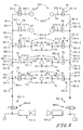
In another embodiment of the invention illustrated in Fig. 8, each
module 124 (again, excepting the module 124-1 at the end of the changer 120 remote
from the dispensing equipment 44) includes two parallel second through passageways
30-1 and 30-2, each having an input port 80-1, 80-2, respectively, and an output port
82-1, 82-2, respectively. Each second through passageway 30-1, 30-2 serves as a
pass-through for a fluid selected from among the fluids controlled by the various
modules 124, again, unless one or both of the selected fluids is (are) the fluid
controlled by that module 124's respective valve(s) 34-1 and (or) 34-2. Then, that
module 124's valve(s) 34-1 and (or) 34-2 is (are) actuated, providing communication
between its first passageway 28 and the selected one or both of the second through
passageways 30-1, 30-2.
The selected fluid(s) then pass(es) out of the color changer 120 through
the output port(s) 82-1 and (or) 82-2 of the second through passageway(s) 30-1 and
(or) 30-2 of the most downstream module 124-n in the color changer 120. Again,
downstream in the fluid supply circuits 40-1, 40-2 between the output ports 82-1, 82-2
of the last module 124-n in the series, the fluid supply circuits 40-1, 40-2 include
pressure regulators 86-1, 86-2 to ensure that the fluids supplied to the dispensing
equipment 44-1, 44-2, whether they be solvent, color 1, color 2, ... or color (n-2), are
supplied to the dispensing equipment 44-1, 44-2 at pressures controlled by the
pressure regulators 86-1, 86-2. The outputs of the fluid pressure regulators 86-1, 86-2
flow through other valves (not shown) typically internal to the dispensing equipment
44-1, 44-2 and are dispensed by the dispensing equipment 44-1, 44-2. When these
valves are not open, none of the color modules 124s'valves 34 are typically open.
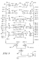
Another fluid circuit incorporating a color changer 120 is illustrated in
Fig. 9. In this embodiment, each module 124 (again, excepting the one at the end of
the changer 120 remote from the dispensing equipment 44) includes two second
through passageways 30-1 and 30-2, each having an input port 80 and an output port
82. Each second through passageway 30-1, 30-2 serves as a pass-through for a fluid
selected from among the fluids controlled by the various modules 124, unless one or
both of the selected fluids is (are) the fluid controlled by that module 124's respective
valve(s) 34-1 and (or) 34-2. Then, that module 124's valve(s) 34-1 and (or) 34-2 is
(are) actuated, providing communication between its first passageway 28 and the
selected one or both of the second through passageways 30-1, 30-2.
The selected fluid(s) then pass(es) out of the color changer 120 through
the output port(s) 82-1 and (or) 82-2 of the second through passageway(s) 30-1 and
(or) 30-2. Downstream in the fluid supply circuits 40-1, 40-2 between the output
ports 82-1, 82-2 of the last module 124 in the series (here, the color (n-2) module), the
fluid supply circuits 40-1, 40-2 include selector valves 200-1, 200-2, respectively,
which are separately operable to provide either the fluid flowing in second through
passageway 30-1 or the fluid flowing in second through passageway 30-2 to a
pressure regulator 86 to ensure that the fluid supplied to the dispensing equipment 44,
whether it be solvent, color 1, color 2, ... or color (n-2), is supplied to the dispensing
equipment 44 at a pressure controlled by the pressure regulator 86. The output of the
fluid pressure regulator 86 flows through another valve (not shown) typically internal
to the dispensing equipment 44 and is dispensed by the dispensing equipment 44.
When this valve is not open, none of the color modules 124s'valves 34 are typically
open.
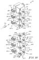
The construction of each individual module 24, 124, can further be
appreciated by referring to Figs. 1-6. Each module 24, 124 includes, in addition to its
first through passageway 28 and one (in modules 24) or two (in modules 124) second
through passageway(s) 30, 30-1, 30-2: one (in modules 24) or two (in modules 124)
paint shutoff valve seat(s) 210, 210-1, 210-2; one (in modules 24) or two (in modules
124) manual paint shutoff valve closure(s) 212 which cooperate(s) with the paint
shutoff valve seat(s)210, 210-1, 210-2 to turn off the flow of fluid to that module 24's
or 124's respective first through passageway 28; one (in modules 24) or two (in
modules 124) valve(s) 34, 34-1, 34-2; one (in modules 24) or two (in modules 124)
weep port(s) 214 in the location(s) and for the purpose(s) disclosed in U. S. S. N. 09/ ,
and, alignment pins 216 (shown only in Fig. 1). Alignment pins 216 aid in the
alignment of the output port(s) 82, 82-1, 82-2 of each module 24, 124 upstream in the
fluid circuit with the input port(s) 80, 80-1, 80-2 of a respective module 24, 124
downstream in the fluid circuit. Ports 62 and 72 are provided with sanitary fittings
218 to provide smooth, uniform interior dimensions in passageways 28 to ease the
passage of (a) pig(s) 219 (Figs. 10 and 11) through passageways 28 in order to
recover undispensed amounts of the various colors, thereby minimizing the waste of
colors which remain in the circuit after their respective dispensing cycles. Externally,
the modules 24, 124 are configured with means such as, for example, grooves 220,
slots 222 and complementarily located threaded holes, which permit modules 24, 124
to be assembled, using, for example, threaded fasteners 224, into a color changer 20,
120 "stack" including any desired number of modules 24, 124, corresponding to any
desired number of colors.
It should be understood that other components, such as, for example, a
flowmeter, may be included in the circuit 40, 40-1, 40-2, for example, on the output
port 82 of the most downstream module 24-n, 124-n.