EP1319258B1 - Continuity testing in communication networks - Google Patents
Continuity testing in communication networks Download PDFInfo
- Publication number
- EP1319258B1 EP1319258B1 EP01922342A EP01922342A EP1319258B1 EP 1319258 B1 EP1319258 B1 EP 1319258B1 EP 01922342 A EP01922342 A EP 01922342A EP 01922342 A EP01922342 A EP 01922342A EP 1319258 B1 EP1319258 B1 EP 1319258B1
- Authority
- EP
- European Patent Office
- Prior art keywords
- communication
- communication hub
- message
- call
- continuity
- Prior art date
- Legal status (The legal status is an assumption and is not a legal conclusion. Google has not performed a legal analysis and makes no representation as to the accuracy of the status listed.)
- Expired - Lifetime
Links
- 238000004891 communication Methods 0.000 title claims abstract description 1057
- 238000012360 testing method Methods 0.000 title claims abstract description 203
- 238000000034 method Methods 0.000 claims abstract description 66
- 238000012790 confirmation Methods 0.000 claims description 57
- 238000012545 processing Methods 0.000 claims description 29
- 230000011664 signaling Effects 0.000 description 14
- 238000012546 transfer Methods 0.000 description 7
- 230000004044 response Effects 0.000 description 5
- 239000012141 concentrate Substances 0.000 description 4
- 230000003466 anti-cipated effect Effects 0.000 description 3
- 238000012986 modification Methods 0.000 description 3
- 230000004048 modification Effects 0.000 description 3
- 238000001514 detection method Methods 0.000 description 2
- 238000011161 development Methods 0.000 description 2
- 230000001960 triggered effect Effects 0.000 description 2
- 230000005540 biological transmission Effects 0.000 description 1
- 238000010586 diagram Methods 0.000 description 1
- 230000006870 function Effects 0.000 description 1
- 238000009434 installation Methods 0.000 description 1
- 230000007774 longterm Effects 0.000 description 1
- 238000011160 research Methods 0.000 description 1
Images













Classifications
-
- H—ELECTRICITY
- H04—ELECTRIC COMMUNICATION TECHNIQUE
- H04M—TELEPHONIC COMMUNICATION
- H04M7/00—Arrangements for interconnection between switching centres
- H04M7/12—Arrangements for interconnection between switching centres for working between exchanges having different types of switching equipment, e.g. power-driven and step by step or decimal and non-decimal
- H04M7/1205—Arrangements for interconnection between switching centres for working between exchanges having different types of switching equipment, e.g. power-driven and step by step or decimal and non-decimal where the types of switching equipement comprises PSTN/ISDN equipment and switching equipment of networks other than PSTN/ISDN, e.g. Internet Protocol networks
- H04M7/1295—Details of dual tone multiple frequency signalling
-
- H—ELECTRICITY
- H04—ELECTRIC COMMUNICATION TECHNIQUE
- H04M—TELEPHONIC COMMUNICATION
- H04M3/00—Automatic or semi-automatic exchanges
- H04M3/22—Arrangements for supervision, monitoring or testing
-
- H—ELECTRICITY
- H04—ELECTRIC COMMUNICATION TECHNIQUE
- H04M—TELEPHONIC COMMUNICATION
- H04M3/00—Automatic or semi-automatic exchanges
- H04M3/22—Arrangements for supervision, monitoring or testing
- H04M3/26—Arrangements for supervision, monitoring or testing with means for applying test signals or for measuring
- H04M3/28—Automatic routine testing ; Fault testing; Installation testing; Test methods, test equipment or test arrangements therefor
- H04M3/32—Automatic routine testing ; Fault testing; Installation testing; Test methods, test equipment or test arrangements therefor for lines between exchanges
-
- H—ELECTRICITY
- H04—ELECTRIC COMMUNICATION TECHNIQUE
- H04M—TELEPHONIC COMMUNICATION
- H04M7/00—Arrangements for interconnection between switching centres
- H04M7/006—Networks other than PSTN/ISDN providing telephone service, e.g. Voice over Internet Protocol (VoIP), including next generation networks with a packet-switched transport layer
-
- H—ELECTRICITY
- H04—ELECTRIC COMMUNICATION TECHNIQUE
- H04Q—SELECTING
- H04Q3/00—Selecting arrangements
- H04Q3/0016—Arrangements providing connection between exchanges
- H04Q3/0062—Provisions for network management
- H04Q3/0087—Network testing or monitoring arrangements
-
- H—ELECTRICITY
- H04—ELECTRIC COMMUNICATION TECHNIQUE
- H04M—TELEPHONIC COMMUNICATION
- H04M19/00—Current supply arrangements for telephone systems
- H04M19/02—Current supply arrangements for telephone systems providing ringing current or supervisory tones, e.g. dialling tone or busy tone
-
- H—ELECTRICITY
- H04—ELECTRIC COMMUNICATION TECHNIQUE
- H04M—TELEPHONIC COMMUNICATION
- H04M7/00—Arrangements for interconnection between switching centres
- H04M7/12—Arrangements for interconnection between switching centres for working between exchanges having different types of switching equipment, e.g. power-driven and step by step or decimal and non-decimal
- H04M7/1205—Arrangements for interconnection between switching centres for working between exchanges having different types of switching equipment, e.g. power-driven and step by step or decimal and non-decimal where the types of switching equipement comprises PSTN/ISDN equipment and switching equipment of networks other than PSTN/ISDN, e.g. Internet Protocol networks
- H04M7/128—Details of addressing, directories or routing tables
-
- H—ELECTRICITY
- H04—ELECTRIC COMMUNICATION TECHNIQUE
- H04M—TELEPHONIC COMMUNICATION
- H04M7/00—Arrangements for interconnection between switching centres
- H04M7/12—Arrangements for interconnection between switching centres for working between exchanges having different types of switching equipment, e.g. power-driven and step by step or decimal and non-decimal
- H04M7/1205—Arrangements for interconnection between switching centres for working between exchanges having different types of switching equipment, e.g. power-driven and step by step or decimal and non-decimal where the types of switching equipement comprises PSTN/ISDN equipment and switching equipment of networks other than PSTN/ISDN, e.g. Internet Protocol networks
- H04M7/129—Details of providing call progress tones or announcements
-
- H—ELECTRICITY
- H04—ELECTRIC COMMUNICATION TECHNIQUE
- H04Q—SELECTING
- H04Q2213/00—Indexing scheme relating to selecting arrangements in general and for multiplex systems
- H04Q2213/13106—Microprocessor, CPU
-
- H—ELECTRICITY
- H04—ELECTRIC COMMUNICATION TECHNIQUE
- H04Q—SELECTING
- H04Q2213/00—Indexing scheme relating to selecting arrangements in general and for multiplex systems
- H04Q2213/1316—Service observation, testing
-
- H—ELECTRICITY
- H04—ELECTRIC COMMUNICATION TECHNIQUE
- H04Q—SELECTING
- H04Q2213/00—Indexing scheme relating to selecting arrangements in general and for multiplex systems
- H04Q2213/13166—Fault prevention
-
- H—ELECTRICITY
- H04—ELECTRIC COMMUNICATION TECHNIQUE
- H04Q—SELECTING
- H04Q2213/00—Indexing scheme relating to selecting arrangements in general and for multiplex systems
- H04Q2213/13176—Common channel signaling, CCS7
-
- H—ELECTRICITY
- H04—ELECTRIC COMMUNICATION TECHNIQUE
- H04Q—SELECTING
- H04Q2213/00—Indexing scheme relating to selecting arrangements in general and for multiplex systems
- H04Q2213/13204—Protocols
-
- H—ELECTRICITY
- H04—ELECTRIC COMMUNICATION TECHNIQUE
- H04Q—SELECTING
- H04Q2213/00—Indexing scheme relating to selecting arrangements in general and for multiplex systems
- H04Q2213/1329—Asynchronous transfer mode, ATM
-
- H—ELECTRICITY
- H04—ELECTRIC COMMUNICATION TECHNIQUE
- H04Q—SELECTING
- H04Q2213/00—Indexing scheme relating to selecting arrangements in general and for multiplex systems
- H04Q2213/13349—Network management
-
- H—ELECTRICITY
- H04—ELECTRIC COMMUNICATION TECHNIQUE
- H04Q—SELECTING
- H04Q2213/00—Indexing scheme relating to selecting arrangements in general and for multiplex systems
- H04Q2213/13389—LAN, internet
Definitions
- the invention relates to communication networks, and specifically, to a method and system for providing continuity testing in communication networks.
- Continuity testing in communication networks is one method of ensuring the quality of services.
- a continuity test ensures bearer channel connectivity prior to call completion.
- the continuity test is generally performed on a pre-determined percentage of calls to verify bearer channel connectivity between a pair of switches.
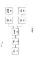
- FIG. 1 illustrates a block diagram that illustrates a public switched telephone network (PSTN) using signaling system 7 (SS7) that performs a continuity test.
- PSTN public switched telephone network
- SS7 signaling system 7
- the calling party removes the receiver from the calling party's telephone 100.
- the originating switch 101 detects the off-hook and provides a dial tone to telephone 100. Responsive to receiving the dial tone, the user enters the digits for a call destination.
- the originating switch 101 processes the entered digits and provides an initial address message (IAM) to the network 102.
- the IAM message includes a continuity test flag that indicates to the network 102 that a continuity test will be performed on the bearer channel between the network 102 and the originating switch 101.
- the originating switch 101 then sends a test tone over the bearer channel to the network 102. Responsive to sending the test tone, the originating switch 101 starts a timer. The network 102 loops the test tone back to the originating switch 101. If the test tone is received back in the originating switch 101 before the timer times-out, the continuity test is successful and the originating switch 101 sends a continuity test message to the network 102. The continuity message confirms the continuity test is complete and successful. If the test tone is not received back in the originating switch 101 before the timer times-out, the continuity test is failed and the call is cleared.
- the network 102 Responsive to a successful continuity test, the network 102 provides an IAM message to the terminating switch 103 and reserves a call connection between the originating switch 101 and the terminating switch 103.
- the terminating switch 103 sends an address complete message (ACM) to the network 102 and the call is completed between telephones 100 and 104 in the conventional fashion.
- ACM address complete message
- packet-networks do not effectively support continuity testing. These networks typically require installation of communication hubs in the customer premises.
- the communication hubs are controlled by an out-of-band call agent that does not have knowledge of bearer path connectivity when call setup messages are received from the communication hubs.
- Call tones are generated in communication networks to provide callers with feedback regarding the status of calls and call connections. Examples of specific call tones include a ringback tone, a busy signal tone, and a reorder tone. The reorder tone is sometimes referred to as a fast busy signal in the art.
- call tones are provided in communication networks by a terminating communication device upon completion of the call connection. In some applications however, call tones can be provided by an originating communication device by triggering the call tone generation using a control or signaling channel.
- the network in FIG. 1 also illustrates an example of call tone control and generation for a call session in the PSTN.
- the calling party removes the receiver from the calling party's telephone 100.
- the originating switch 101 detects the off-hook and provides a dial tone to the calling party's telephone 100. Responsive to receiving the dial tone, the user enters the digits for a call destination.
- the originating switch 101 processes the entered digits and provides a call setup message to the network 102.
- the network 102 provides the call setup message to the terminating switch 103 arid reserves a connection between the originating switch 101 and the terminating switch 103.
- the terminating switch 103 provides an acknowledgment message to the network 102.
- the terminating switch 103 If the terminating switch 103 detects the called party's telephone 104 is off-hook or busy, the terminating switch 103 provides busy signal tones over the network 102 to the calling party's telephone 100. If the terminating switch 103 does not detect that the called party's telephone 104 is off-hook or busy, the terminating switch 103 provides ringback tones over the network 102 to the calling party's telephone 100. The terminating switch 103 also rings the called party's telephone 104 to announce the incoming call.
- FIG. 2 illustrates another example of call tone generation and control for a call session in a packet communication network.
- the calling party removes the receiver from the calling party's telephone 200.
- the originating communication hub 201 detects the off-hook event and provides an off-hook message to the network 202. Responsive to receiving the off-hook message, the network 202 provides a dial tone to the calling party's telephone 200 via the originating communication hub 201. Responsive to receiving the dial tone the user enters the digits for the call destination.
- the originating communication hub 201 detects the digits and provides the digits to the network 202.
- the network 202 processes the digits and generates a setup message for a terminating communication hub 203 connected to the called party's telephone 204. Responsive to receiving the setup message, the terminating communication hub 203 provides a setup neknowledgment message to the network 202. If the called party's telephone 204 is off-hook or busy, the terminating communication hub 203 provides busy signal tones over the network 202 and communication hub 201 to the calling party's telephone 200. If the terminating communication hub 203 does not detect the called party's telephone 203 is off-hook or busy, the terminating communication hub 203 provides ringback tones over the network 202 and communication hub 201 to the calling party's telephone 200. The terminating communication hub 203 also rings the called party's telephone 204 to announce the incoming call.
- U.S. Patent No. 5,438,570 describes service observing equipment that monitors, detects and makes call records from digital and audio information on an individual call basis.
- the observation equipment can monitor both a Signaling System Seven (SS #7) and a CCITT #7 in which data packets are transmitted along the high speed data links separated from the telecommunication audio channels.
- the call record indicates how trouble free and efficiently (or how troubled and inefficiently) individual calls are processed by the telecommunication network.
- a plurality of separate memory locations are assigned on an individual call basis, for the duration of a given call, to store data received over any of many data links and communication channels relative to that given call. After the call has terminated, the accumulated data is analyzed to determine the call's final disposition.
- a call record is restored in memory for reports and/or transmitted to a printer or another processor. Then, the emplied memory locations are reassigned to accumulate data relative to new calls.
- the service observation equipment can trap annoyance calls and generate disposition reports on threshold levels of operation, provide live observing of calls in progress, generate real-time and/or long term peak and average link occupancy reports, and display a listing of time stamped messages for a specific call in order to provide for protocol analysis.
- WO Publication 98/23053 describes a telecommunications signaling processor for processing Signaling System #7 (SS7) telecommunication signaling messages to select ATM virtual connections and provide control messages indicating a selected ATM virtual connections.
- the signaling processor comprises: a computer system, data structures, originating process logic, and terminating process logic.
- the data structure has trunk circuit table, trunk group table, exception table, ANI table, called number table, and a routing table. Originating process logic and terminating logic are stored in the computer system and process information from (SS7) signaling messages that relates to an originating circuit and terminating circuit and access the data structures to request a terminating ATM virtual connection in response to the request from the originating process.
- SS7 Signaling System #7
- WO Publication 99/28827 describes methods and systems for a distributed scalable hardware independent system that supports multiple functions regarding management and support of communications over a packet-based network.
- the communications supported by these methods and systems include Voice Over Internet Protocol ("VOIP”), voice over Asynchronous Transfer Mode (“ATM”), video conferencing, data transfer, telephony, and downloading video or other data.
- VOIP Voice Over Internet Protocol
- ATM voice over Asynchronous Transfer Mode
- video conferencing video conferencing
- data transfer data transfer
- telephony and downloading video or other data.
- call agent which is composed of various objects distributed along a CORBA software bus, for exercising call management over two endpoints communicating over a packet-based network.
- the present invention advances the art by providing a communication system that performs continuity testing in a packet communication network.
- service assurance is provided before call completion and cady detection of network failures is realized.
- the invention provides a communication system that provides call tones in communication networks at points proximate a calling device.
- Some examples of call tones that could be provided include without limitation, ringback tones, busy signal tones, and reorder tones.
- the communication system combines call tone generation and control with continuity testing in the network and utilizes the call tone messaging to perform the continuity test.
- network resources required for call completion are reduced because call tones are provided at points proximate the calling device and a separate continuity test of the bearer channel is unnecessary.
- a communication system configured to test for continuity on a channel of a packet communication network
- the communication system comprising a first communication hub connected to the packet communication network and a second communication hub connected to the packet communication network, wherein the communication system is configured to connect a call between the first communication hub and the second communication hub over the packet communication network, wherein the packet communication network is configured to generate and transmit a continuity test instruction to the second communication hub, the communication system characterized by the second communication hub being configured to process the continuity test instruction and a network address of the first communication hub to generate a request for continuity acknowledgment message, and transmit the request for continuity acknowledgment message to the first communication hub over the channel of the packet communication network; the first communication hub being configured to receive the request for continuity acknowledgment message over the packet communication network, to process the request for continuity acknowledgment message and a network address of the second communication hub to generate a continuity acknowledgment message, and to transmit the continuity acknowledgment message to the second communication hub over the channel of the packet communication network; and the second communication hub being configured to process the continuity acknowledg
- a method of operating a communication system to test continuity on a channel of a packet communication network wherein the communication system comprises a first communication hub, a second communication hub, and the packet communication network, wherein the communication system is configured to connect a call between the first communication hub and the second communication hub over the packet communication network, wherein the packet communication network generates and transmits a continuity test instruction to the second communication hub, the method characterized by the steps of in the second communication hub, processing the continuity test instruction and a network address of the first communication hub to generate a request for continuity acknowledgment message and transmitting the request for continuity acknowledgment message to the first communication hub over the channel of the packet communication network; in the first communication hub, receiving the request for continuity acknowledgment message over the channel of the packet communication network, processing the request for continuity acknowledgment message and a network address of the second communication hub to generate a continuity acknowledgment message, and transmitting the continuity acknowledgement message to the second communication hub over the channel of the packet communication network; and in the second communication hub processing the continuity acknowledgment message to
- the communication system includes a communication hub comprised of a processor and an interface.
- the processor is configured to process a continuity test instruction to generate a request for continuity acknowledgement message.
- the interface is configured to receive the continuity test instruction and transmit the request for continuity acknowledgement message. If a continuity acknowledgement message is received in the communication hub responsive to the request for continuity acknowledgement message, the continuity test is passed. If the continuity acknowledgement message is not receive in response to the request for continuity acknowledgement message, the continuity test is failed.
- the communication hub is comprised of an interface coupled to a processor and a tone generator.
- the processor is configured to process a continuity test instruction to generate a request for continuity acknowledgement message.
- the processor is also configured to process a continuity test tone instruction to direct the tone generator to provide continuity test tones to another communication network.
- the tone generator is configured to generate the continuity test tones under control of the processor.
- the interface is configured to receive the continuity test instruction and the continuity test tone instruction and transmit the request for continuity acknowledgment message and the continuity test tones for the processor.
- the communication hub is comprised of a processor, an interface, and a tone generator.
- the tone generator is configured to generate the call tones under control of the processor.
- the processor is configured to process an in-band call tone request message that includes a request to provide call tones to a call device connected to the communication hub.
- the processor is further configured to generate a continuity acknowledgment message in response to the call tone request message and direct the tone generator to provide call tones to the call device.
- the interface is configured to receive the call tone request message and transmit the continuity acknowledgment message and the call tones.
- the communication hub is comprised of an interface coupled to a processor and a tone generator.
- the tone generator is configured to generate the call tones under control of the processor.
- the processor is configured to process an in-band call tone request message to direct the tone generator to provide the call tones to a call device.
- the interface is configured to receive the call tone request message and transmit the call tones to the call device.
- an on-network call session is defined as a call session between two devices connected to the same communication network.
- An off-network to on-network call session and an on-network to off-network call session are defined as an incoming call session or an outgoing call session, respectively, between two devices connected to different communication networks. For example, an incoming call session or an outgoing call session between a call device connected to a packet network and a call device connected to the PSTN.
- In-band is defined as using the bearer portion of a communication path, for example, over the bearer channel in an asynchronous transfer mode (ATM) connection.
- ATM asynchronous transfer mode
- IP Internet Protocol
- in-band could simply be a pair of addresses, such as the address of the originating device and the address of the terminating device.
- FIG. 3 illustrates a communication system 310 according to the present invention.
- FIG. 3 depicts call devices 300 and 306, communication hubs 301, 303, and 305, communication network 302 and second communication network 304.
- Communication hub 301 is connected to call device 300 and communication network 302.
- Communication network 302 is connected to communication hubs 303 and 305.
- Communication hub 303 is connected to call device 306 and second communication network 304 is connected to communication hub 305.
- Call devices 300 and 306 could be conventional call devices that use digital and analog telephony format. Some examples of call devices 300, 306, and 307 are devices configured to provide voice, data, and video communications.
- Communication network 302 and second communication network 304 could be different communication networks. In some examples of the present invention, communication network 302 is a packet network and second communication network 304 could be any other network including without limitation, a wireless network, a packet network, an internet, or the PSTN. Those skilled in the art will appreciate the communication networks 302 and 304 would include various conventional components not shown on FIG. 3 for clarity.
- Communication hub 301 could be any communication device capable of receiving a continuity test instruction and process the continuity test instruction to provide a request for continuity acknowledgment message.
- Communication hub 303 could be any communication device capable of receiving and processing the request for continuity acknowledgment message to generate and transmit a continuity acknowledgment message. If communication hub 301 receives the continuity acknowledgment message responsive to its request, the continuity test is successful. If communication hub 301 does not receive the continuity acknowledgment message responsive to its request, the continuity test is failed.
- Some examples of communication hub 301 include without limitation, a residential communication hub, a private branch exchange (PBX), and a switch.
- PBX private branch exchange
- Communication hub 303 could also incorporate the features of communication hub 301 to receive a continuity test instruction and process the continuity test instruction to provide a request for continuity acknowledgment message.
- communication hub 301 could incorporate the features of communication hub 303 to receive and process the request for continuity acknowledgment message to generate and transmit a continuity acknowledgment message.
- Communication hub 305 could be any communication device capable of interfacing between communication network 302 and second communication network 304.
- Communication hub 305 could incorporate the features of communication hubs 301 and 303 to perform continuity testing in communication network 302.
- Communication hub 305 could also be configured to receive a continuity test tones instruction and process the continuity test tones instruction to provide continuity test tones to second communication network 304. If communication hub 305 receives an acknowledgment responsive to providing the continuity test tones, the continuity test is successful. In some examples of the present invention, the acknowledgment could be receipt of the continuity test tones through a conventional loopback method in second communication network 304. If communication hub 305 does not receive the acknowledgment responsive to providing the continuity test tones, the continuity test is failed.
- Some examples of communication hub 305 include without limitation, a network device such as a voice gateway, a PBX, and a switch.
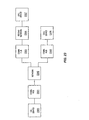
- FIG. 4 depicts an example of communication hubs 301, 303, and 305 according to the present invention, namely communication hub 400.
- Communication hub 400 comprises processor 401 coupled to interface 402.
- Interface 402 is connected to communication paths 403 and 404.
- Communication paths 403 and 404 could be conventional communication paths.
- interface 402 could be a part of processor 401, such as where interface 402 is in the same processing circuitry or included on the same chip as processor 401.
- communication hub 400 would include other conventional components not shown on FIG. 3 for clarity, depending on the type of device and its operation in a network environment.
- Processor 401 could be any processor capable of processing various messages to conduct continuity testing of a bearer channel. For example, processor 401 could process a continuity test instruction to generate a request for continuity acknowledgment message for another communication device. If processor 401 receives the continuity acknowledgment message from the another communication device the continuity test is successful. If processor 401 does not receive the continuity acknowledgment message from the another communication device the continuity test is failed. Processor 401 could also receive and process a request for continuity acknowledgment message from another communication device to generate a continuity acknowledgment message for the another communication device.
- the request for continuity acknowledgment message and the continuity acknowledgment message are provided over the bearer channel, thus ensuring bearer channel connectivity prior to call completion.
- Interface 402 could be any interface that receives messages for processor 401 and transmits messages for processor 401.
- Interface 402 could also be a voice interface that acts as a POTS interface or packet interface, supervises messages, channels voice communications, or resolves contention between voice lines or voice communication paths.
- Interface 402 could also be a data or video interface that manages data stream, video stream, performs asynchronous time division, or concentrates data and video lines or paths.
- One example of interface 402 includes without limitation an asynchronous transfer mode (ATM) interface capable of handling ATM messaging for processor 401 over communication path 404 and capable of handling analog signaling for processor 401 over communication path 403.
- Interface 402 could handle numerous such communication paths although only communication paths 403 and 404 are shown for clarity.
- ATM asynchronous transfer mode
- FIG. 5 depicts another example of communication hubs 301, 303, and 305 according to the present invention, namely communication hub 500.
- Communication hub 500 is comprised of a processor 505, a tone generator 501, and an interface 502. Interface 502 is connected to processor 505, tone generator 501, and communication paths 503 and 504. Communication paths 503 and 504 could be conventional communication paths. Processor 505 is also connected to tone generator 501. Those skilled in the art will appreciate that in some embodiments of the invention tone generator 501 and interface 502 could be a part of processor 505, such as where tone generator 501 and interface 502 are in the same processing circuitry or included on the same chip as processor 505. Those skilled in the art will also understand that communication hub 500 would include other conventional components not shown on FIG. 5 for clarity, depending on the type of device and its operation in a network environment.
- Processor 505 could be any processor capable of processing various messages to conduct continuity testing of a bearer channel. For example, processor 505 could process a continuity test instruction to generate a request for continuity acknowledgment message for another communication device. If processor 505 receives the continuity acknowledgment message from the another communication device the continuity test is successful. If processor 505 does not receive the continuity acknowledgment message from the another communication device the continuity test is failed. Processor 505 could also receive and process a request for continuity acknowledgment message from another communication device to generate and transmit a continuity acknowledgment message for the another communication device.
- the request for continuity acknowledgment message and the continuity acknowledgment message are provided over the bearer channel, thus ensuring bearer channel connectivity prior to call completion.
- processor 505 is also configured to process a continuity test tone instruction to direct tone generator 501 to provide continuity test tones to another communication network. If processor 505 receives an acknowledgment message from the another communication network the continuity test is successful. If processor 505 does not receive the acknowledgment message from the another communication network the continuity test is failed.
- bearer channel connectivity in the local communication network and other communication networks is confirmed prior to call completion.
- Interface 502 could be any interface that receives messages for processor 505 and transmits messages for processor 505.
- Interface 502 could also be a voice interface that acts as a POTS interface or packet interface, supervises messages, channels voice communications, or resolves contention between voice lines or voice communication paths.
- Interface 502 could also be a data or video interface that manages data stream, video stream, performs asynchronous time division, or concentrates data and video lines or paths.
- One example of interface 502 includes without limitation an asynchronous transfer mode (ATM) interface capable of handling ATM messaging for processor 505 over communication path 504 and capable of handling analog signaling for processor 505 over communication path 503.
- Interface 502 could handle numerous such communication paths although only communication paths 503 and 504 are shown for clarity.
- ATM asynchronous transfer mode
- FIGS. 6-12 are message sequence charts illustrating various examples of the operation of a communication hub according to the present invention. It is anticipated, however, that various modifications to these examples will be readily apparent to those skilled in the art. The principles defined herein may also be applied to other embodiments without the use of inventive faculty. Thus, the present invention is not intended to be limited to the examples shown below but is to be accorded the widest scope consistent with the principles and novel features disclosed herein.
- FIGS. 6 and 7 illustrate a message sequence chart illustrating an example according to the present invention of a successful continuity test between communication hubs 301 and 305.
- the call session is an on-network to off-network call session between communication hubs 301 and 305.
- call device 300 goes off-hook and an off-hook event is detected in communication hub 301.
- Communication hub 301 provides an off-hook message to communication network 302.
- communication network 302 provides a dial tone to call device 300 via communication hub 301.
- Caller entered digits are transmitted from call device 300 to communication network 302 via communication hub 301.
- communication network 302 provides a create connection message to communication hub 301.
- the create connection message to communication hub 301 creates a half duplex bearer connection between communication network 302 and communication hub 301. Responsive to the connection setup, communication hub 301 provides an acknowledgment message to communication network 302. The acknowledgment message includes the network address of communication hub 301. Responsive to receiving the digits, communication network 302 also provides a create connection message to communication hub 305. The create connection message to communication hub 305 creates a full duplex bearer connection between communication network 302 and communication hub 305. Responsive to the connection setup, communication hub 305 provides an acknowledgment message to communication network 302. The acknowledgment message includes the network address of communication hub 305. The create connection message to communication hub 305 includes the address of communication hub 301 and includes a continuity test instruction.
- communication hub 305 Responsive to the continuity test instruction, communication hub 305 provides a request for continuity acknowledgment message to communication hub 301. Substantially concurrently, communication network 302 provides an update message to communication hub 301 that includes the address of communication hub 305. Responsive to the request for continuity acknowledgment message, communication hub 301 provides a continuity acknowledgment message to communication hub 305.
- the request for continuity acknowledgment and the continuity acknowledgment message are provided in-band over the bearer channel by communication hubs 305 and 301.
- the completion of this messaging in-band ensures the bearer channel connectivity prior to call completion.
- communication hub 305 Responsive to receiving the continuity acknowledgment message, communication hub 305 provides a continuity confirmation message to communication network 302 confirming the continuity acknowledgment message was received and provides call tones to call device 300. In this example the call tones are ringback call tones.
- communication network 302 provides an IAM message to second communication network 304.
- second communication network 304 Responsive to processing the IAM message, second communication network 304 provides an ACM message to communication network 302. Responsive to the called device (not shown) going off-hook, second communication network 304 provides an answer (ANM) message to communication network 302.
- communication network 302 Responsive to receiving the ANM message, communication network 302 provides an ANM message to communication hub 305. Responsive to receiving the ANM message, communication hub 305 stops providing the ringback tones to call device 300. Substantially concurrently, communication network 302 modifies the half duplex bearer connection between communication hub 301 and communication network 302 to a full duplex bearer connection to complete the call.
- the continuity test could be performed on all calls.
- the continuity test could also be performed on a random unbiased basis for a certain percentage of calls based upon request from communication network 302.
- the request could be based on a frequency index established and adjusted based on the bearer network stability and availability.
- the request for the continuity acknowledgment message and the continuity acknowledgment message could be retransmitted a pre-determined number of times at pre-determined intervals with duplicated received messages ignored.
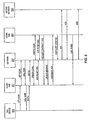
- FIG. 8 is a message sequence chart illustrating an example according to the present invention of a failed continuity test between communication hubs 301 and 305.
- the call session is an on-network to off-network call session between communication hubs 301 and 305.
- call device 300 goes off-hook and an off-hook event is detected in communication hub 301.
- Communication hub 301 provides an off-hook message to communication network 302.
- communication network 302 provides a dial tone to call device 300 via communication hub 301.
- Caller entered digits are transmitted from call device 300 to communication network 302 via communication hub 301.
- communication network 302 Responsive to receiving the digits, provides a create connection message to communication hub 301.
- the create connection message to communication hub 301 creates a half duplex bearer connection between communication network 302 and communication hub 301. Responsive to the connection setup, communication hub 301 provides an acknowledgment message to communication network 302. The acknowledgment message includes the network address of communication hub 301. Responsive to receiving the digits, communication network 302 also provides a create connection message to communication hub 305. The create connection message to communication hub 305 creates a full duplex bearer connection between communication network 302 and communication hub 305. Responsive to the connection setup, communication hub 305 provides an acknowledgment message to communication network 302. The acknowledgment message includes the network address of communication hub 305. The create connection message to communication hub 305 includes the address of communication hub 301 and includes a continuity test instruction.
- communication hub 305 Responsive to the continuity test instruction, communication hub 305 provides a request for continuity acknowledgment to communication hub 301. Substantially concurrently, communication network 302 provides an update message to communication hub 301 that includes the address of communication hub 305. Communication network 302 also starts an internal timer. In this case the bearer channel is inoperative and the continuity acknowledgment message is not received in communication hub 305. The internal timer in communication network 302 times-out before the continuity confirmation message from communication hub 305 is received. Responsive to the timer timing-out, communication network 302 clears the call. In another example, communication hub 305 could start an internal timer and send an error message to communication network 302 if the continuity acknowledgment message is not received prior to the timer-out of the timer. In this case communication network 302 clears the call responsive to receiving the error message from communication hub 305.
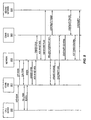
- FIGS. 9 and 10 illustrate a message sequence chart illustrating an example of a successful continuity test in communication network 302 and in second communication network 304.
- the call session is an on-network to off-network call session between communication hubs 301 and 305.
- call device 300 goes off-hook and an off-hook event is detected in communication hub 301.
- Communication hub 301 provides an off-hook message to communication network 302.
- communication network 302 provides a dial tone to call device 300 via communication hub 301.
- Caller entered digits are transmitted from call device 300 to communication network 302 via communication hub 301.
- communication network 302 Responsive to receiving the digits, provides a create connection message to communication hub 301.
- the create connection message to communication hub 301 creates a half duplex bearer connection between communication network 302 and communication hub 301. Responsive to the connection setup, communication hub 301 provides an acknowledgment message to communication network 302. The acknowledgment message includes the network address of communication hub 301. Responsive to receiving the digits, communication network 302 also provides a create connection message to communication hub 305. The create connection message to communication hub 305 creates a full duplex bearer connection between network 302 and communication hub 305. Responsive to the connection setup, communication hub 305 provides an acknowledgment message to communication network 302. The acknowledgment message includes the network address of communication hub 305.
- the create connection message to communication hub 305 includes the address of communication hub 301, a continuity test instruction to perform the continuity test of the bearer channel in communication network 302, and a continuity test tone instruction to perform a continuity test of the bearer channel in second communication network 304.
- Communication network 302 also sends an IAM message to second communication network 304.
- the IAM message includes a continuity test flag to inform second communication network 304 that a continuity test will be performed before the call is completed.
- communication hub 305 Responsive to the continuity test instruction, communication hub 305 provides a request for continuity acknowledgment message to communication hub 301 and provides continuity test tones to second communication network 304. Substantially concurrently, communication network 302 provides an update message to communication hub 301 that includes the address of communication hub 305. Responsive to the request for continuity acknowledgment message, communication hub 301 provides a continuity acknowledgment message to communication hub 305.
- Second communication network 304 process the continuity test tones by looping the tones back to communication hub 305. Responsive to receiving the continuity acknowledgment message, communication hub 305 provides a continuity confirmation message to communication network 302. The continuity confirmation message confirms receipt of the continuity acknowledgment message, and thus, the bearer channel connectivity in communication network 302. Responsive to receiving the continuity test tones back from second communication network 304, communication hub 305 provides a continuity test tone confirmation message to communication network 302. The continuity test tone confirmation message confirms receipt of the continuity tones, and thus, the bearer channel connectivity in second communication network 304. Responsive to receiving the continuity test tone confirmation message, communication network 302 provides a continuity test message to second communication network 304. The continuity test message confirms the continuity test is complete and successful.
- second communication network 304 provides an ACM message to communication network 302.
- communication hub 305 provides call tones to call device 300.
- the call tones are ringback call tones.
- communication network 302 provides an ANM message to communication hub 305.
- communication hub 305 stops providing the ringback tones to call device 300.
- communication network 302 modifies the half duplex bearer connection between communication hub 301 and communication network 302 to a full duplex bearer connection to complete the call.
- the continuity test in second communication network 304 could be performed on all calls.
- the continuity test in second communication network 304 could also be performed on a random unbiased basis for a certain percentage of calls based upon request from communication network 302.
- the request could be based on a frequency index established and adjusted based on the bearer network stability and availability.
- the request continuity test message, the continuity acknowledgment message, and the continuity tones could be retransmitted a pre-determined number of times at pre-determined intervals with duplicated received messages ignored.
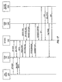
- FIG. 11 illustrates a message sequence chart illustrating an example of a successful continuity test for an on-network call session between communication hubs 301 and 303 according to the present invention.
- call device 300 goes off-hook and an off-hook event is detected in communication hub 301.
- Communication hub 301 provides an off-hook message to communication network 302.
- communication network 302 provides a dial tone to call device 300 via communication hub 301.
- Caller entered digits are transmitted from call device 300 to communication network 302 via communication hub 301.
- communication network 302 Responsive to receiving the digits, provides a create connection message to communication hub 301.
- the create connection message to communication hub 301 creates a half duplex bearer connection between communication network 302 and communication hub 301. Responsive to the connection setup, communication hub 301 provides an acknowledgment message to communication network 302. The acknowledgment message includes the network address of communication hub 301. Responsive to receiving the digits, communication network 302 also provides a create connection message to communication hub 303. The create connection message to communication hub 303 creates a full duplex bearer connection between network 302 and communication hub 303. Responsive to the connection setup, communication hub 303 provides an acknowledgment message to communication network 302. The acknowledgment message includes the network address of communication hub 303. The create connection message to communication hub 303 includes the address of communication hub 301 and includes a continuity test instruction.
- communication hub 303 Responsive to the continuity test instruction, communication hub 303 provides a request for continuity acknowledgment to communication hub 301. Substantially concurrently, communication network 302 provides an update message to communication hub 301 that includes the address of communication hub 303. Responsive to the request for continuity acknowledgment message, communication hub 301 provides a continuity acknowledgment message to communication hub 303.
- the request for continuity acknowledgment message and the continuity acknowledgment message are provided in-band over the bearer channel by communication hubs 303 and 301.
- the completion of this messaging in-band ensures the bearer channel connectivity prior to call completion.
- communication hub 303 Responsive to receiving the continuity acknowledgment message, communication hub 303 provides a continuity confirmation message to communication network 302 confirming the continuity acknowledgment message was received and provides call tones to call device 300. In this case the call tones are ringback tones.
- communication hub 303 stops the ringback tones and provides an off-hook message to communication network 302. Responsive to receiving the off-hook message, communication network 302 modifies the half duplex bearer connection between communication hub 301 and communication network 302 to a full duplex bearer connection to complete the call.
- the continuity test could be performed on all calls.
- the continuity test could also be performed on a random unbiased basis for a certain percentage of calls based upon request from communication network 302.
- the request could be based on a frequency index established and adjusted based on the bearer network stability and availability.
- the request continuity test message and continuity acknowledgment message could be retransmitted a pre-determined number of times at pre-determined intervals with duplicated received messages ignored.
- FIG. 12 illustrates a message sequence chart illustrating an example of a continuity test for an off-network to on-network call session according to the present invention.
- an off-hook signal is detected in second communication network 304 from a call device (not shown).
- Second communication network 304 processes the off-hook detection in a conventional manner to obtain the caller entered digits.
- second communication network 304 provides an IAM message to communication network 302 via communication hub 305.
- the IAM message includes a continuity test flag that indicates to communication network 302 that a continuity test is being performed in second communication network 304.
- communication network 302 Responsive to receiving the IAM message, provides a create loopback message to communication hub 305.
- the create loopback message provides communication hub 305 with loopback instructions for the continuity test tones.
- Second communication network 304 then provides continuity test tones, which are looped back to second communication network 304 by communication hub 305. Responsive to receiving the continuity test tones back, second communication network 304 provides a continuity test message to communication network 302 to indicate a successful test. Responsive to the continuity test message, communication network 302 could perform a continuity test of its bearer channel as described above or process the call in a conventional manner.
- communication network 302 could provide a create loopback message to communication hub 301 responsive to receiving the IAM with continuity test flag.
- the continuity test tones would be looped back by communication hub 301, thus eliminating the need for a separate continuity test in communication network 302.
- FIG. 13 illustrates a communication system according to the present invention.
- FIG. 13 depicts call devices 1300, 1306, and 1307, communication hubs 1301, 1303, and 1305, communication network 1302 and second communication network 1304.
- Communication hub 1301 is connected to call device 1300 and communication network 1302.
- Communication network 1302 is connected to communication hubs 1303 and 1305.
- Second communication network 1304 is connected to communication hub 1305 and call device 1307.
- Communication hub 1303 is connected to call device 1306.
- Call devices 1300, 1306, and 1307 could be conventional call devices that use digital and analog telephony format. Some examples of call devices 1300, 1306, and 1307 are devices configured to provide voice, data, and video communications.
- Communication network 1302 and second communication network 1304 could be different communication networks. In some examples of the present invention, communication network 1302 is a packet network and second communication network 1304 could be any other network including without limitation, a wireless network, a packet network, an internet, or the PSTN. Those skilled in the art will appreciate the communication networks 1302 and 1304 would include various conventional components not shown on FIG. 13 for clarity.
- Communication hub 1301 could be any communication device capable of: 1) receiving an in-band call tone request message that includes a request to provide call tones to call device 1300, 2) generating and transmitting a continuity acknowledgment message, and 3) providing the call tones to call device 1300.
- Some examples of communication hub 1301 include without limitation, a switch, a private branch exchange (PBX), and a residential communication hub.
- PBX private branch exchange
- Communication hub 1305 could be any communication device capable of interfacing between communication network 1302 and second communication network 1304. Communication hub 1305 could: 1) receive an in-band call tone request message that includes a request to provide call tones to one of call devices 1300 and 1307, 2) generate and transmit a continuity acknowledgment message, and 3) provide the call tones to one of call devices 1300 and 1307. Some examples of communication hub 1305 include without limitation, a network device such as a voice gateway and a switch.
- Communication hub 1303, could be any communication device capable of: 1) receiving an in-band call tone request message that includes a request to provide call tones to call device 1306, 2) generating and transmitting a continuity acknowledgment message, and 3) providing the call tones to call device 1306.
- Some examples of communication hub 1301 include without limitation, a switch, a PBX, and a residential communication hub.
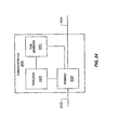
- FIG. 14 depicts an example of communication hubs 1301, 1303, and 1305 according to the present invention, namely communication hub 1400.
- Communication hub 1400 is comprised of a processor 1405, a tone generator 1401, and an interface 1402. Interface 1402 is connected to processor 1405, tone generator 1401, and communication paths 1403 and 1404. Communication paths 1403 and 1404 could be conventional Chrunication paths. Processor 1405 is also connected to tone generator 1401. Those skilled in the art will appreciate that in some embodiments of the invention tone generator 1401 and interface 1402 could be a part of processor 1405, such as where tone generator 1401 and interface 1402 are in the same processing circuitry or included on the same chip as processor 1405. Those skilled in the art will also understand that communication hub 1400 would include other conventional components not shown on FIG. 14 for clarity, depending on the type of device and its operation in a network environment.
- Processor 1405 could be any processor capable of processing various messages to: 1) generate the continuity acknowledgment message, 2) direct tone generator 1401 to provide the call tones to a call device, 3) direct tone generator 1401 to stop providing call tones to the call device, 4) direct tone generator 1401 to provide continuity test tones, and 5) generate a request for a continuity acknowledgment message from another communication hub.
- Tone generator 1401 could be a conventional device that provides tones under the control of processor 1405.
- Interface 1402 could be any interface that receives messages for processor 1405 and transmits messages for processor 1405.
- Interface 1402 could also be a voice interface that acts as a POTS interface or packet interface, supervises messages, channels voice communications, or resolves contention between voice lines or voice communication paths.
- Interface 1402 could also be a data or video interface that manages data stream, video stream, performs asynchronous time division, or concentrates data and video lines or paths.
- One example of interface 1403 includes without limitation an asynchronous transfer mode (ATM) interface capable of handling ATM messaging for processor 1405 over communication path 1404 and capable of handling analog signaling for processor 1405 over communication path.
- Interface 1402 could handle numerous such communication paths although only communication paths 1403 and 1404 are shown for clarity.
- ATM asynchronous transfer mode
- FIGS. 15-22 illustrate message sequence charts for various examples of the operation of a communication hub according to the present invention. It is anticipated, however, that various modifications to these examples will be readily apparent to those skilled in the art. The principles defined herein may also be applied to other embodiments without the use of inventive faculty. Thus, the present invention is not intended to be limited to the examples shown below but is to be accorded the widest scope consistent with the principles and novel features disclosed herein.
- FIGS. 15-16 illustrate a message sequence chart illustrating an example according to the present invention of an on-network call session between communication hubs 1301 and 1303.
- continuity testing is accomplished by exchanging call tone request and continuity acknowledgment messages over the bearer channel.
- call device 1300 goes off-hook and an off-hook event is detected in communication hub 1301.
- Communication hub 1301 provides an off-hook message to communication network 1302.
- communication network 1302 provides a dial tone to call device 1300 via communication hub 1301.
- Caller entered digits are transmitted from call device 1300 to communication network 1302 via communication hub 1301.
- communication network 1302 provides a create connection message to communication hub 1301.
- the create connection message to communication hub 1301 creates a half duplex bearer connection between communication network 1302 and communication hub 1301. Responsive to the connection setup, communication hub 1301 provides an acknowledgment message to communication network 1302. The acknowledgment message includes the network address of communication hub 1301. Responsive to receiving the digits, communication network 1302 also provides a create connection message to communication hub 1303. The create connection message to communication hub 1303 creates a full duplex bearer comection between network 1302 and communication hub 1303. Responsive to the connection setup, communication hub 1303 provides an acknowledgment message to communication network 1302. The acknowledgment message includes the network address of communication hub 1303. The create connection message to communication hub 1303 includes the address of communication hub 1301 and includes a request continuity test instruction. Responsive to receiving the request continuity test instruction, communication hub 1303 provides an in-band call tone request message to communication hub 1301 that includes a request to provide call tones to call device 1300. In this case the call tones are ringback tones.
- communication hub 1301 Responsive to receiving the call tone request message, communication hub 1301 provides the call tones to call device 1300. Substantially concurrently, communication network 1302 provides an update message to communication hub 1301 that includes the address of communication hub 1303. Responsive to the update message, communication hub 1301 provides a continuity acknowledgment message to communication hub 1303.
- the call tone request message and the continuity acknowledgment message are provided over the bearer channel. Thus, if the continuity acknowledgment message is received in communication hub 1303, bearer channel connectivity is confirmed.
- communication hub 1303 rings call device 1306 to announce the incoming call.
- Communication hub 1303 also provides a continuity confirmation message to communication network 1302 to confirm receipt of the continuity acknowledgment message.
- communication network 1302 starts an internal timer responsive to sending the request continuity test instruction to communication hub 1303. If the internal timer times-out and the continuity confirmation message is not received, the continuity test has failed and communication network 1302 clears the call.
- communication hub 1303 could send an error message to communication network 1302 if the continuity acknowledgment message is not received. Responsive to receiving the error message, communication network 1302 clears the call.
- communication hub 1303 Responsive to receiving an off-hook message from call device 1306, communication hub 1303 provides an off-hook message to communication network 1302. Substantially concurrently, communication hub 1303 provides a stop call tones message to communication hub 1301. Communication hub 1301, responsive to receiving the stop call tones message, stops providing the call tones to call device 1300. Responsive to receiving the off-hook message, communication network 1302 provides a request for on-hook notification message to communication hub 1303 and modifies the connection between network 1302 and communication hub 1301 to a full duplex bearer connection to complete the call between call device 1300 and call device 1306.
- the continuity test provided through the call tone messaging could be performed on all calls as described above.
- the continuity test could also be performed on a random unbiased basis for a certain percentage of calls based upon request from communication network 1302.
- the request could be based on a frequency index established and adjusted based on the bearer network stability and availability.
- the continuity acknowledgment from communication hub 1301 is optional.
- communication hub 1303 would ring call device 1306 responsive to the time-out of an internal timer.
- the continuity acknowledgment message could also be used to confirm that the call tones are being provided by communication hub 1301.
- the call tone request message and continuity acknowledgment message could be retransmitted a pre-determined number of times at pre-determined intervals with duplicated received messages ignored.
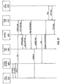
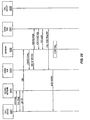
- FIGS. 17 and 18 illustrate a message sequence chart for an example, according to the present invention, of an on-network to off-network call session between communication hubs 1301 and 1305.
- communication network 1302 performs a separate continuity test of the bearer channel as the call tones are provided by second network 1304.
- call device 1300 goes off-hook and an off-hook event is detected in communication hub 1301.
- Communication hub 1301 provides an off-hook message to communication network 1302.
- Responsive to receiving the off-hook message communication network 1302 provides a dial tone to call device 1300 via communication hub 1301. Caller entered digits are transmitted from call device 1300 to communication network 1302 via communication hub 1301.
- communication network 1302 Responsive to receiving the digits, communication network 1302 provides a create connection message to communication hub 1301. The create connection message to communication hub 1301 creates a half duplex bearer connection between communication network 1302 and communication hub 1301. Responsive to the connection setup, communication hub 1301 provides an acknowledgment message to communication network 1302. The acknowledgment message includes the network address of communication hub 1301. Responsive to receiving the digits, communication network 1302 also provides a create connection message to communication hub 1305. The create connection message to communication hub 1305 creates a full duplex bearer connection between network 1302 and communication hub 1305. Responsive to the connection setup, communication hub 1305 provides an acknowledgment message to communication network 1302. The acknowledgment message includes the network address of communication hub 1305.
- the create connection message to communication hub 1305 includes the address of communication hub 1301 and includes a request continuity test instruction.
- communication network 1302 provides an update message to communication hub 1301 that includes the network address of communication hub 1305.
- communication hub 1305 provides a request for continuity acknowledgment message to communication hub 1301.
- communication hub 1301 provides a continuity acknowledgment message to communication hub 1305.
- the request for continuity acknowledgment and the continuity acknowledgment message are provided over the bearer channel, thus ensuring the bearer channel connectivity prior to call completion.
- communication hub 1305 provides a continuity confirmation message to communication network 1302 confirming the continuity acknowledgment message was received.
- communication network 1302 provides an IAM message to second communication network 1304. Responsive to processing the IAM message, second communication network 1304 provides an ACM message to communication network 1302. Second communication network 1304 also provides call tones to call device 1300 via communication hub 1305. Responsive to the called device (not shown) going off-hook, second communication network 1304 provides an answer (ANM) message to communication network 1302. Responsive to receiving the ANM message, communication network 1302 modifies the half duplex connection between communication hub 1301 and communication network 1302 to a full duplex bearer connection to complete the call.
- ACM answer
- FIGS. 19 and 20 illustrate a message sequence chart for an example, according to the present invention, of an off-network to on-network call session between communication hubs 1301 and 1305.
- continuity testing is accomplished by exchanging call tone request and continuity acknowledgment messages over the bearer channel.
- call device 1307 goes off-hook.
- Second communication network 1304 detects the off-hook event and provides a dial tone to call device 1307. Responsive to receipt of caller entered digits, second communication network 1304 provides an IAM message to communication network 1302 via communication hub 1305.
- the IAM message includes a continuity test flag that indicates to communication network 1302 that a continuity test is being performed in second communication network 1304.
- communication network 1302 Responsive to receiving the IAM message, communication network 1302 provides a create loopback message to communication hub 1345.
- the create loopback message provides communication hub 1305 with loopback instructions for the continuity test tone.
- Second communication network 1304 performs the continuity test.
- the continuity test comprises transmitting test tones over the bearer channel and waiting for the loopback of the tone by communication hub 1305.
- second communication network 1304 Responsive to receiving the continuity test tones back, second communication network 1304 provides a continuity test message to communication network 1302 to indicate a successful test.
- communication network 1302 Responsive to the continuity test message, communication network 1302 provides a create connection message to communication hub 1301.
- the create connection message to communication hub 1301 creates a full duplex bearer connection between communication network 1302 and communication hub 1301.
- communication hub 1301 provides an acknowledgment message to communication network 1302.
- the acknowledgment message includes the network address of communication hub 1301.
- communication network 1302 also provides a create connection message to communication hub 1305.
- the create connection message to communication hub 1305 creates a half duplex bearer connection between network 1302 and communication hub 1305.
- communication hub 1305 provides an acknowledgment message to communication network 1302.
- the acknowledgment message includes the network address of communication hub 1305.
- the create connection message for the full duplex bearer connection includes the network address of communication hub 1305 and includes the continuity test request instruction.
- communication hub 1301 Responsive to the continuity test request instruction, communication hub 1301 provides a call tone request message to communication hub 1305 with the request for communication hub 1303 to provide call tones to call device 1307. Responsive to the call tone request message, communication hub 1301 provides the call tones to call device 1307.
- communication network 1302 updates communication hub 1305 with the address of communication hub 1301 and provides an ACM message to second communication network 1304. Responsive to providing the call tones to call device 1307, communication hub 1305 provides a continuity acknowledgment message to communication hub 1301. Responsive to receiving the continuity acknowledgment message, communication hub 1301 rings call device 1300 to announce the incoming call. Communication hub 1301 also provides a continuity confirmation message to communication network 1302 to confirm the bearer channel connectivity. Responsive to receiving an off-hook message from call device 1300, communication hub 1301 provides an off-hook message to communication network 1302. Substantially concurrently communication hub 1301 provides a stop call tones message to communication hub 1305.
- Communication network 1302 sends a request for on-hook notification message to communication hub 1301 and modifies the connection between communication network 1302 and communication hub 1305 to a full duplex bearer connection to complete the call between call device 1307 and call device 1300.
- FIGS. 21 and 22 illustrate a message sequence chart for an example of an on-network to off-network call session where the continuity test is performed in communication network 1302 and in second communication network 1304 by a communication hub according the present invention.
- communication network 1302 performs a separate continuity test of the bearer channel in communication network 1302 as the call tones are provided by second network 1304.
- call device 1300 goes off-hook and an off-hook event is detected in communication hub 1301.
- Communication hub 1301 provides an off-hook message to communication network 1302.
- Responsive to receiving the off-hook message communication network 1302 provides a dial tone to call device 1300 via communication hub 1301.
- Caller entered digits are transmitted from call device 1300 to communication network 1302 via communication hub 1301. Responsive to receiving the digits, communication network 1302 provides a create connection message to communication hub 1301. The create connection message to communication hub 1301 creates a half duplex bearer connection between communication network 1302 and communication hub 1301. Responsive to the connection setup, communication hub 1301 provides an acknowledgment message to communication network 1302. The acknowledgment message includes the network address of communication hub 1301. Responsive to receiving the digits, communication network 1302 also provides a create connection message to communication hub 1305. The create connection message to communication hub 1305 creates a full duplex bearer connection between network 1302 and communication hub 1305. Responsive to the connection setup, communication hub 1305 provides an acknowledgment message to communication network 1302.
- the acknowledgment message includes the network address of communication hub 1305.
- the create connection message for the full duplex bearer connection includes the network address of communication hub 1301, includes a request continuity test instruction with the request for communication hub 1305 to perform a continuity test of the bearer channel in communication network 1302, and includes a request continuity test tone instruction with a request for communication hub 1305 to perform a continuity test of the bearer channel in second communication network 1304.
- Communication network 1302 also provides an LAM message to second communication network 1304.
- the IAM includes a continuity test flag to inform second communication network 1304 that a continuity test will be performed before the call is completed. Responsive to the continuity test instructions, communication hub 1305 provides a request for continuity acknowledgment message to communication hub 1301. Communication hub 1305 also provides continuity test tones to second communication network 1304.
- Communication network 1302 provides an update message to communication hub 1301 that includes the network address of communication hub 1305. Responsive to receiving the request for the continuity acknowledgment, communication hub 1301 provides a continuity acknowledgment message to communication hub 1305. Responsive to receiving the continuity acknowledgment message, communication hub 1305 provides a confirmation message to communication network 1302 confirming the bearer channel connectivity in communication network 1302. Second communication network 1304 processes the continuity test tones by looping the tones back to communication hub 1305. Responsive to receiving the continuity test tones back from second communication network 1304, communication hub 1305 provides a continuity test tone confirmation message to communication network 1302 confirming receipt of the continuity tones and the bearer channel connectivity in second communication network 1304.
- communication network 1302 Responsive to receiving the continuity test tone confirmation message, communication network 1302 provides a continuity test message to second communication network 1304 to indicate the continuity test success. Responsive to the continuity test message, second communication network 1304 provides an ACM message to communication network 1302. Call tones are provided by second communication network 1304 via communication hub 1305 to call device 1300. Responsive to receiving an ANM message from second communication network 1304, communication network 1302 modifies the connection between communication network 1302 and communication hub 1301 to a full duplex bearer connection to complete the call.
- the continuity test in second communication network 1304 could be performed on all calls.
- the continuity test in second communication network 1304 could also be performed on a random unbiased basis for a certain percentage of calls based upon request from communication network 1302.
- the request could be based on a frequency index established and adjusted based on the bearer network stability and availability.
- the request continuity test message, the continuity acknowledgment message, and the continuity tones could be retransmitted a pre-determined number of times at pre-determined intervals with duplicated received messages ignored.
- FIG. 23 illustrates a communication system according to the present invention
- FIG. 23 depicts call devices 2300, 2306, and 2307, communication hubs 2301, 2303, and 2305, communication network 2302, and second communication network 2304.
- Communication hub 2301 is connected to call device 2300 and communication network 2302.
- Communication network 2302 is connected to communication hubs 2303 and 2305.
- Communication hub 2305 is connected to call device 2306.
- Second communication network 2304 is connected to communication hub 2303 and call device 2307.
- Call devices 2300, 2306, and 2307 could be conventional call devices that use digital and analog telephony format. Some examples of call devices 2300, 2306, and 2307 are devices configured to provide voice, data, and video communications.
- Communication network 2302 and second communication network 2304 could be different communication networks. In some examples of the present invention, communication network 2302 is a packet network and second communication network 2304 could be any other network including without limitation, a wireless network, a packet network, an internet, or the PSTN. Those skilled in the art will appreciate the communication networks 2302 and 2304 would include various conventional components not shown on FIG. 23 for clarity.
- Communication hub 2301 could be any communication device capable of: 1) receiving an in-band call tone request message that includes a request to provide call tones to call device 2300, and 2) process the call tone request message to provide call tones to call device 2300.
- Communication hub 2305 could be any communication device capable of: 1) providing the call tone request message that includes the request to provide call tones to call device 2300, and 2) process a confirmation message that confirms the call tones are being provided to call device 2300.
- Some examples of communication hubs 2301 and 2305 include without limitation, a switch, a private branch exchange (PBX), and a residential communication hub.
- PBX private branch exchange
- Communication hub 2301 could also incorporate the features of communication hub 2305 to generate an in-band call tone request message to provide call tones to call device 2306 and process a confirmation message that confirms call tones are being provided to call device 2306.
- communication hub 2305 could incorporate the features of communication hub 2301 to receive the call tone request message and provide call tones to call device 2306.
- Communication hub 2303 could be any communication device capable of interfacing between communication network 2302 and second communication network 2304. Communication hub 2303 could also incorporate the features of communication hubs 2301 and 2305 to process an in-band call tone request message to provide call tones to call device 2307. Communication hub 2303 could also generate call tone request messages for communication hubs 2301 and 2305 to provide call tones to call devices 2300 and 2306 respectively. Communication hub 2303 could also process confirmation messages confirming the call tones are being provided to call devices 2300 and 2306. Communication hub 2303 could also interface between communication network 2302 and second communication network 2304 to provide call tones generated by second communication network 2304 to one of call devices 2300 and 2306. Some examples of communication hub 2303 include without limitation, a network a voice gateway, a PBX, and a switch.
- FIG. 24 depicts an example of communication hubs 2301, 2303, and 2305 according to the present invention, namely communication hub 2400.
- Communication hub 2400 is comprised of a processor 2405, a tone generator 2401, and an interface 2402. Interface 2402 is connected to processor 2405, tone generator 2401, and communication paths 2403 and 2404. Communication paths 2403 and 2404 could be conventional communication paths.
- Processor 2405 is also connected to tone generator 2401.
- tone generator 2401 and interface 2402 could be a part of processor 2405, such as where tone generator 2401 and interface 2402 are in the same processing circuitry or included on the same chip as processor 2405.
- communication hub 2400 typically would include other conventional components not shown on FIG. 24 for clarity, depending on the type of device and its operation in a network environment.
- Processor 2405 could be any processor capable of processing various messages to: 1) direct tone generator 2401 to provide the call tones to a call device, 2) direct tone generator 2401 to stop providing the call tones to the call device, 3) provide confirmation that the call tones were provided to the call device, 4) generate in-band call tone request messages for other communication hubs; and 5) process confirmations from other communication hubs that call tones were provided to other call devices.
- Tone generator 2401 could be a conventional device that provides call tones under the control of processor 2405.
- Interface 2402 could be any interface that receives messages for processor 2405 and transmits messages for processor 2405.
- Interface 2402 could also be a voice interface that acts as a POTS interface or packet interface, supervises messages, channels voice communications, or resolves contention between voice lines or voice communication paths.
- Interface 2402 could also be a data or video interface that manages data stream, video stream, performs asynchronous time division, or concentrates data and video lines or paths.
- One example of interface 2402 includes without limitation an asynchronous transfer mode (ATM) interface capable of handling ATM messaging for processor 2405 over communication path 2404 and capable of handling analog signaling for processor 2405 over communication path 2403.
- Interface 2402 could handle numerous such communication paths although only communication paths 2403 and 2404 are shown for clarity.
- ATM asynchronous transfer mode
- FIGS. 25-29 illustrate message sequence charts for various examples of the operation of a communication hub according to the present invention. It is anticipated, however, that various modifications to these examples will be readily apparent to those skilled in the art. The principles defined herein may also be applied to other embodiments without the use of inventive faculty. Thus, the present invention is not intended to be limited to the examples shown below but is to be accorded the widest scope consistent with the principles and novel features disclosed herein.
- FIG. 25 is a message sequence chart illustrating an example according to the present invention of an on-network call session between communication hubs 2301 and 2305.
- communication hub 2301 is the originating communication hub for the call and communication hub 2305 is the terminating communication hub for the call.
- call device 2300 goes off-hook and an off-hook event is detected in communication hub 2301.
- Communication hub 2301 provides an off-hook message to communication network 2302.
- communication network 2302 provides a dial tone to call device 2300 via communication hub 2301.
- Caller entered digits are transmitted from call device 2300 to communication network 2302 via communication hub 2301.
- communication network 2302 provides a create connection message to communication hub 2301.
- the create connection message to communication hub 2301 creates a half duplex bearer connection between communication network 2302 and communication hub 2301. Responsive to the connection setup, communication hub 2301 provides an acknowledgment message to communication network 2302. The acknowledgment message includes the network address of communication hub 2301. Responsive to receiving the digits, communication network 2302 also provides a create connection message to communication hub 2305. The create connection message to communication hub 2305 creates a full duplex bearer connection between network 2302 and communication hub 2305. Responsive to the connection setup, communication hub 2305 provides an acknowledgment message to communication network 2302. The acknowledgment message includes the network address of communication hub 2305. The create connection message to communication hub 2305 includes the address of communication hub 2301 and includes an instruction for ring and ringback tones.
- communication hub 2305 Responsive to the ring and ringback instruction, communication hub 2305 provides an in-band call tone request message to communication hub 2301.
- the call tone request message includes a request for communication hub 2301 to provide ringback tones to call device 2300.
- the call tone request message could be triggered by the completion of the connection setup rather than the network instruction.
- communication hub 2301 Responsive to receiving the call tone request message, communication hub 2301 provides the ringback tones to call device 2300. Substantially concurrently, communication network 2302 updates communication hub 2301 with the address of communication hub 2305. Responsive to the update message, communication hub 2301 provides an in-band call tone confirmation message to communication hub 2305. Alternatively, the call tone confirmation message could be provided over the signaling channel. The call tone confirmation message includes a confirmation that the ringback tones are being provided to call device 2300. Responsive to receiving the confirmation message, communication hub 2305 rings call device 2306 to announce the incoming call. In some examples of the invention, communication hub 2301 may not transmit the confirmation message to communication hub 2305. In this case communication hub 2305 rings call device 2306 responsive to the time-out of an internal timer.
- communication hub 2305 Responsive to receiving an off-hook signal from call device 2306, communication hub 2305 provides an off-hook message to communication network 2302. Substantially concurrently, communication hub 2305 provides an in-band stop call tones message to communication hub 2301. Alternatively, the stop call tones message could be provided over the signaling channel. Responsive to receiving the stop call tones message, communication hub 2301 stops providing the ringback tones to call device 2300. Responsive to receiving the off-hook message, communication network 2302 sends a request for on-hook notification message to communication hub 2305 and modifies the connection between communication network 2302 and communication hub 2301 to a full duplex bearer connection to complete the call.
- communication hub 2305 starts a timer after sending the call tone request message to communication hub 2301. If communication hub 2301 does not respond before the timer times-out, communication hub 2305 provides an error message to communication network 2302 and the call is cleared. Similarly, communication network 2302 starts a timer while waiting for the off-hook message from communication hub 2305. If the timer times-out before the off-hook message is received, communication network 2302 could either perform call forwarding for subscribed customers or stop the call tones and clear the call.
- communication network 2302 sends an instruction to communication hub 2305 to stop ringing call device 2306.
- Communication network 2302 then forwards the call to another communication hub connected to the forwarded call device and the new communication hub exchanges the call tone request message, and in some examples, the confirmation message with communication hub 2301.
- communication hub 2301 recognizes the request is from the same calling party but for a different destination and continues providing the ringback tones.
- the communication hub 2305 could respond to the receipt of audio information to stop providing the ringback tones.
- FIG. 26 illustrates a message sequence chart for an example, according to the present invention, of an on-network call session between communication hubs 2301 and 2305 where call device 2306 is not answered.
- communication hub 2301 is the originating communication hub for the call and communication hub 2305 is the terminating communication hub for the call.
- call device 2300 goes off-hook and an off-hook event is detected in communication hub 2301.
- Communication hub 2301 provides an off-hook message to communication network 2302.
- Responsive to receiving the off-hook message communication network 2302 provides a dial tone to call device 2300 via communication hub 2301. Caller entered digits are transmitted from call device 2300 to communication network 2302 via communication hub 2301.
- communication network 2302 Responsive to receiving the digits, communication network 2302 provides a create connection message to communication hub 2301. The create connection message to communication hub 2301 creates a half duplex bearer connection between communication network 2302 and communication hub 2301. Responsive to the connection setup, communication hub 2301 provides an acknowledgment message to communication network 2302. The acknowledgment message includes the network address of communication hub 2301. Responsive to receiving the digits, communication network 2302 also provides a create connection message to communication hub 2305. The create connection message to communication hub 2305 creates a full duplex bearer connection between network 2302 and communication hub 2305. Responsive to the connection setup, communication hub 2305 provides an acknowledgment message to communication network 2302. The acknowledgment message includes the network address of communication hub 2305.
- the create connection message to communication hub 2305 includes the address of communication hub 2301 and includes an instruction for ring and ringback tones. Responsive to the ring and ringback instruction, communication hub 2305 provides an in-band call tone request message to communication hub 2301.
- the call tone request message includes a request for communication hub 2301 to provide ringback tones to call device 2300.
- communication hub 2301 Responsive to receiving the call tone request message, communication hub 2301 provides the ringback tones to call device 2300. Substantially concurrently, communication network 2302 updates communication hub 2301 with the address of communication hub 2305. Responsive to the update message, communication hub 2301 provides an in-band call tone confirmation message to communication hub 2305. The call tone confirmation message includes a confirmation that the ringback tones are being provided to call device 2300. Responsive to receiving the confirmation message, communication hub 2305 rings call device 2306 to announce the incoming call. Communication hub 2305 also starts an internal timer. Responsive to the time-out of the internal timer, communication hub 2305 transmits an in-band voice announcement to communication hub 2301. The voice announcement indicates that the called party has not answered.
- communication hub 2301 stops playing the ringback tones and provides the voice announcement to the call device 2300. Responsive to detecting an on-hook event in call device 2300, communication hub 2301 provides an on-hook message to the communication network 2302. Responsive to the on-hook message, the communication network 2302 clears the call connections between the communication hubs 2301 and 2305 in a conventional manner to end the call session.
- FIGS. 27 and 28 illustrate a message sequence chart for an example, according to the present invention, of an off-network to on-network call session.
- communication hub 2303 in communication network 2302 is the point proximate the calling device 2307 connected to second communication network 2304.
- call device 2307 goes off-hook.
- Second communication network 2304 detects the off-hook event and provides a dial tone to call device 2307. Responsive to receipt of caller entered digits, second communication network 2304 provides an IAM message to communication network 2302 via communication hub 2303. Responsive to receiving the IAM message, communication network 2302 provides a create connection message to communication hub 2301.
- the create connection message to communication hub 2301 creates a full duplex bearer connection between communication network 2302 and communication hub 2301. Responsive to the connection setup, communication hub 2301 provides an acknowledgment message to communication network 2302. The acknowledgment message includes the network address of communication hub 2301. Responsive to the IAM message, communication network 2302 also provides a create connection message to communication hub 2303. The create connection message to communication hub 2303 creates a half duplex bearer connection between network 2302 and communication hub 2303. Responsive to the connection setup, communication hub 2303 provides an acknowledgment message to communication network 2302. The acknowledgment message includes the network address of communication hub 2303. The create connection message to communication hub 2301 includes the network address of communication hub 2303 and includes the ring and ringback instruction.
- communication hub 2301 Responsive to the ring and ringback instruction, communication hub 2301 provides an in-band call tone request message to communication hub 2303.
- the call tone request message includes a request for communication hub 2303 to provide ringback tones to call device 2307. It should be noted that in some examples of the present invention, the call tone request message could be triggered by the completion of the connection setup
- communication hub 2303 Responsive to receiving the call tone request message, communication hub 2303 provides ringback tones to call device 2307. Substantially concurrently, network 2302 updates communication hub 2303 with the address of communication hub 2301 and provides an ACM message to second communication network 2304. Responsive to providing the ringback tones to call device 2307, communication hub 2303 provides a confirmation message to communication hub 2301 that includes a confirmation that the ringback tones are being provided to call device 2307. Responsive to receiving the confirmation message, communication hub 2301 rings call device 2300 to announce the incoming call. In some examples of the invention, communication hub 2303 may not transmit the confirmation message to communication hub 2301. In this case communication hub 2301 would ring call device 2300 responsive to the time-out of an internal timer.
- communication hub 2301 Responsive to receiving an off-hook signal from call device 2300, communication hub 2301 provides an off-hook message to network 2302. Substantially concurrently communication hub 2301 provides a stop call tones message to communication hub 2303. Communication hub 2303, responsive to receiving the stop call tones message, stops providing the ringback tones to call device 2307. Communication network 2302 sends a request for on-hook notification message to communication hub 2301 and modifies the connection between communication network 2302 and communication hub 2303 to a full duplex bearer connection to complete the call.
- communication hub 2301 starts a timer after sending the call tone request message to communication hub 2303. If communication hub 2303 does not respond before the timer times-out, communication hub 2301 provides an error message to network 2302 and the call is cleared. Similarly, network 2302 starts a timer while waiting for the off-hook message from communication hub 2301. If the timer times-out before the off-hook message is received, network 2302 could either perform call forwarding for subscribed customers or stop the ringback tones and clear the call.
- network 2302 sends a instruction to communication hub 2303 to stop ringing call device 2300 and clears the connection.
- Communication network 2302 could forward the call to another communication hub connected to the forwarded call device or use the same communication hub to establish a connection with a new call device. In either case, communication hub 2301 recognizes the request is from the same calling party but for a different destination and continues transmission of the ringback tones.
- FIG. 29 illustrates a message sequence chart for an example, according to the present invention, of an off-network to on-network call session where the called device 2300 is busy.
- call device 2307 goes off-hook.
- Second communication network 2304 detects the off-hook event and provides a dial tone to call device 2307. Responsive to receipt of caller entered digits, second communication network 2304 provides an IAM message to communication network 2302 via communication hub 2303. Responsive to receiving the IAM message, communication network 2302 provides a create connection message to communication hub 2301. The create connection message to communication hub 2301 creates a full duplex bearer connection between communication network 2302 and communication hub 2301. Responsive to the connection setup, communication hub 2301 provides an acknowledgment message to communication network 2302.
- the acknowledgment message includes the network address of communication hub 2301. Responsive to the IAM message, communication network 2302 also provides a create connection message to communication hub 2303. The create connection message to communication hub 2303 creates a half duplex bearer connection between network 2302 and communication hub 2303. Responsive to the connection setup, communication hub 2303 provides an acknowledgment message to communication network 2302. The acknowledgment message includes the network address of communication hub 2303. The create connection message to communication hub 2301 includes the address of communication hub 2303 and includes an instruction for ring and ringback tones. Responsive to the ring and ringback instruction, communication hub 2301 detects that call device 2300 is already off-hook or busy and provides an off-hook message to communication network 2302.
- communication hub 2301 provides an in-band call tone request message to communication hub 2303.
- the call tone request message includes a request for communication hub 2303 to provide busy signal tones to call device 2307. Responsive to receiving the request, communication hub 2303 provides busy signal tones to call device 2307. Network 2302, responsive to receiving the off-hook message, clears the call.
- the bandwidth required for call completion is significantly reduced because call tones are provided proximate the calling device 2307.
- an emergency 911 calling scenario such as an attendant call back scenario where the caller is still in an off-hook state
- some special treatment is required. For example, a receiver off-hook signal could be sent to the caller who is off-hook. During this time, audible ringing could be returned to the attendant. After a pre-determined time the connections would be modified to allow the attendant to cut through the audio path.
- the above-described elements can be comprised of instructions that are stored on storage media.
- the instructions can be retrieved and executed by a processor.
- Some examples of instructions are software, program code, and firmware.
- Some examples of storage media are memory devices, tape, disks, integrated circuits, and servers.
- the instructions are operational when executed by the processor to direct the processor to operate in accord with the invention.
- the term "processor" refers to a single processing device or a group of inter-operational processing devices. Some examples of processors are integrated circuits and logic circuitry. Those skilled in the art are familiar with instructions, processors, and storage media.
Landscapes
- Engineering & Computer Science (AREA)
- Signal Processing (AREA)
- Computer Networks & Wireless Communication (AREA)
- Monitoring And Testing Of Exchanges (AREA)
- Data Exchanges In Wide-Area Networks (AREA)
- Telephonic Communication Services (AREA)
- Communication Cables (AREA)
Abstract
Description
- This application claims priority to prior nonprovisional U.S. applications 09/523,813, 09/537,054, and 09/537,057, which are incorporated herein by reference.
- Not applicable
- Not applicable
- The invention relates to communication networks, and specifically, to a method and system for providing continuity testing in communication networks.
- The development of advanced communication networks has taken on critical importance with the dramatic rise in consumer demand for higher quality services. Continuity testing in communication networks is one method of ensuring the quality of services. A continuity test ensures bearer channel connectivity prior to call completion. The continuity test is generally performed on a pre-determined percentage of calls to verify bearer channel connectivity between a pair of switches.
- FIG. 1 illustrates a block diagram that illustrates a public switched telephone network (PSTN) using signaling system 7 (SS7) that performs a continuity test. On FIG. 1 the calling party removes the receiver from the calling party's
telephone 100. The originatingswitch 101 detects the off-hook and provides a dial tone totelephone 100. Responsive to receiving the dial tone, the user enters the digits for a call destination. The originatingswitch 101 processes the entered digits and provides an initial address message (IAM) to thenetwork 102. The IAM message includes a continuity test flag that indicates to thenetwork 102 that a continuity test will be performed on the bearer channel between thenetwork 102 and theoriginating switch 101. The originatingswitch 101 then sends a test tone over the bearer channel to thenetwork 102. Responsive to sending the test tone, the originatingswitch 101 starts a timer. Thenetwork 102 loops the test tone back to the originatingswitch 101. If the test tone is received back in the originatingswitch 101 before the timer times-out, the continuity test is successful and the originatingswitch 101 sends a continuity test message to thenetwork 102. The continuity message confirms the continuity test is complete and successful. If the test tone is not received back in the originatingswitch 101 before the timer times-out, the continuity test is failed and the call is cleared. Responsive to a successful continuity test, thenetwork 102 provides an IAM message to the terminatingswitch 103 and reserves a call connection between the originatingswitch 101 and the terminatingswitch 103. The terminatingswitch 103 sends an address complete message (ACM) to thenetwork 102 and the call is completed betweentelephones - Unfortunately, packet-networks do not effectively support continuity testing. These networks typically require installation of communication hubs in the customer premises. The communication hubs are controlled by an out-of-band call agent that does not have knowledge of bearer path connectivity when call setup messages are received from the communication hubs.
- Call tones are generated in communication networks to provide callers with feedback regarding the status of calls and call connections. Examples of specific call tones include a ringback tone, a busy signal tone, and a reorder tone. The reorder tone is sometimes referred to as a fast busy signal in the art. Typically, call tones are provided in communication networks by a terminating communication device upon completion of the call connection. In some applications however, call tones can be provided by an originating communication device by triggering the call tone generation using a control or signaling channel.
- The network in FIG. 1 also illustrates an example of call tone control and generation for a call session in the PSTN. On FIG. 1, the calling party removes the receiver from the calling party's
telephone 100. The originatingswitch 101 detects the off-hook and provides a dial tone to the calling party'stelephone 100. Responsive to receiving the dial tone, the user enters the digits for a call destination. The originatingswitch 101 processes the entered digits and provides a call setup message to thenetwork 102. Thenetwork 102 provides the call setup message to the terminatingswitch 103 arid reserves a connection between the originatingswitch 101 and the terminatingswitch 103. In response to receiving the call setup message, the terminatingswitch 103 provides an acknowledgment message to thenetwork 102. If the terminatingswitch 103 detects the called party'stelephone 104 is off-hook or busy, the terminatingswitch 103 provides busy signal tones over thenetwork 102 to the calling party'stelephone 100. If the terminatingswitch 103 does not detect that the called party'stelephone 104 is off-hook or busy, the terminatingswitch 103 provides ringback tones over thenetwork 102 to the calling party'stelephone 100. The terminatingswitch 103 also rings the called party'stelephone 104 to announce the incoming call. - FIG. 2 illustrates another example of call tone generation and control for a call session in a packet communication network. On FIG. 2 the calling party removes the receiver from the calling party's
telephone 200. The originatingcommunication hub 201 detects the off-hook event and provides an off-hook message to thenetwork 202. Responsive to receiving the off-hook message, thenetwork 202 provides a dial tone to the calling party'stelephone 200 via theoriginating communication hub 201. Responsive to receiving the dial tone the user enters the digits for the call destination. The originatingcommunication hub 201 detects the digits and provides the digits to thenetwork 202. Thenetwork 202 processes the digits and generates a setup message for a terminatingcommunication hub 203 connected to the called party'stelephone 204. Responsive to receiving the setup message, the terminatingcommunication hub 203 provides a setup neknowledgment message to thenetwork 202. If the called party'stelephone 204 is off-hook or busy, the terminatingcommunication hub 203 provides busy signal tones over thenetwork 202 andcommunication hub 201 to the calling party'stelephone 200. If the terminatingcommunication hub 203 does not detect the called party'stelephone 203 is off-hook or busy, the terminatingcommunication hub 203 provides ringback tones over thenetwork 202 andcommunication hub 201 to the calling party'stelephone 200. The terminatingcommunication hub 203 also rings the called party'stelephone 204 to announce the incoming call. - The following references further illustrate continuity testing in the prior art. U.S. Patent No. 5,438,570 describes service observing equipment that monitors, detects and makes call records from digital and audio information on an individual call basis. The observation equipment can monitor both a Signaling System Seven (SS #7) and a CCITT #7 in which data packets are transmitted along the high speed data links separated from the telecommunication audio channels. The call record indicates how trouble free and efficiently (or how troubled and inefficiently) individual calls are processed by the telecommunication network. A plurality of separate memory locations are assigned on an individual call basis, for the duration of a given call, to store data received over any of many data links and communication channels relative to that given call. After the call has terminated, the accumulated data is analyzed to determine the call's final disposition. A call record is restored in memory for reports and/or transmitted to a printer or another processor. Then, the emplied memory locations are reassigned to accumulate data relative to new calls. In addition, the service observation equipment can trap annoyance calls and generate disposition reports on threshold levels of operation, provide live observing of calls in progress, generate real-time and/or long term peak and average link occupancy reports, and display a listing of time stamped messages for a specific call in order to provide for protocol analysis.
- WO Publication 98/23053 describes a telecommunications signaling processor for processing Signaling System #7 (SS7) telecommunication signaling messages to select ATM virtual connections and provide control messages indicating a selected ATM virtual connections. The signaling processor comprises: a computer system, data structures, originating process logic, and terminating process logic. The data structure has trunk circuit table, trunk group table, exception table, ANI table, called number table, and a routing table. Originating process logic and terminating logic are stored in the computer system and process information from (SS7) signaling messages that relates to an originating circuit and terminating circuit and access the data structures to request a terminating ATM virtual connection in response to the request from the originating process.
- WO Publication 99/28827 describes methods and systems for a distributed scalable hardware independent system that supports multiple functions regarding management and support of communications over a packet-based network. The communications supported by these methods and systems include Voice Over Internet Protocol ("VOIP"), voice over Asynchronous Transfer Mode ("ATM"), video conferencing, data transfer, telephony, and downloading video or other data. These methods and systems use a call agent, which is composed of various objects distributed along a CORBA software bus, for exercising call management over two endpoints communicating over a packet-based network.
- It is a problem in communication networks to provide call tones over the network from the terminating device. Unfortunately, effective call tone generation is not supported because new services such as call waiting, call forwarding, and three-way-calling have increased network bandwidth demands. Therefore, a need exists in the art to free network resources and free bandwidth currently utilized by call tone generation and control in packet communication networks.
- The present invention advances the art by providing a communication system that performs continuity testing in a packet communication network. Advantageously, service assurance is provided before call completion and cady detection of network failures is realized. In another advance in the art, the invention provides a communication system that provides call tones in communication networks at points proximate a calling device. Some examples of call tones that could be provided include without limitation, ringback tones, busy signal tones, and reorder tones. The communication system combines call tone generation and control with continuity testing in the network and utilizes the call tone messaging to perform the continuity test. Thus, network resources required for call completion are reduced because call tones are provided at points proximate the calling device and a separate continuity test of the bearer channel is unnecessary.
- According to one aspect of the invention there is provided a communication system configured to test for continuity on a channel of a packet communication network, the communication system comprising a first communication hub connected to the packet communication network and a second communication hub connected to the packet communication network, wherein the communication system is configured to connect a call between the first communication hub and the second communication hub over the packet communication network, wherein the packet communication network is configured to generate and transmit a continuity test instruction to the second communication hub, the communication system characterized by the second communication hub being configured to process the continuity test instruction and a network address of the first communication hub to generate a request for continuity acknowledgment message, and transmit the request for continuity acknowledgment message to the first communication hub over the channel of the packet communication network; the first communication hub being configured to receive the request for continuity acknowledgment message over the packet communication network, to process the request for continuity acknowledgment message and a network address of the second communication hub to generate a continuity acknowledgment message, and to transmit the continuity acknowledgment message to the second communication hub over the channel of the packet communication network; and the second communication hub being configured to process the continuity acknowledgment message to generate a continuity confirmation message identifying continuity on the channel of the packet communication network, transmit the continuity confirmation message to the packet communication network, process a continuity test tone instruction to generate continuity test tones and provide the continuity test tones over a bearer channel of a communication network that is connected to the second communication hub, and receive the continuity test tones over the bearer channel of the communication network and process the continuity test tones to provide a continuity test tone confirmation message to the packet communication network that includes a confirmation that the continuity test tones were received back from the communication network.
- According to another aspect of the invention there is provided a method of operating a communication system to test continuity on a channel of a packet communication network, wherein the communication system comprises a first communication hub, a second communication hub, and the packet communication network, wherein the communication system is configured to connect a call between the first communication hub and the second communication hub over the packet communication network, wherein the packet communication network generates and transmits a continuity test instruction to the second communication hub, the method characterized by the steps of in the second communication hub, processing the continuity test instruction and a network address of the first communication hub to generate a request for continuity acknowledgment message and transmitting the request for continuity acknowledgment message to the first communication hub over the channel of the packet communication network; in the first communication hub, receiving the request for continuity acknowledgment message over the channel of the packet communication network, processing the request for continuity acknowledgment message and a network address of the second communication hub to generate a continuity acknowledgment message, and transmitting the continuity acknowledgement message to the second communication hub over the channel of the packet communication network; and in the second communication hub processing the continuity acknowledgment message to generate a continuity confirmation message identifying continuity of the channel of the packet communication network, and transmitting the continuity confirmation message to the packet communication network, processing a continuity test tone instruction to generate continuity test tones and providing the continuity test tones over a bearer channel of a communication network that is connected to the second communication hub, receiving the continuity test tones over the bearer channel of the communication network, processing the continuity test tones to generate a continuity test tone confirmation message that includes a confirmation that the continuity test tones were received back from the communication network, and transmitting the continuity test tone confirmation message to the packet communication network.
- In an embodiment of the invention, the communication system includes a communication hub comprised of a processor and an interface. The processor is configured to process a continuity test instruction to generate a request for continuity acknowledgement message. The interface is configured to receive the continuity test instruction and transmit the request for continuity acknowledgement message. If a continuity acknowledgement message is received in the communication hub responsive to the request for continuity acknowledgement message, the continuity test is passed. If the continuity acknowledgement message is not receive in response to the request for continuity acknowledgement message, the continuity test is failed.
- In another embodiment of the present invention, the communication hub is comprised of an interface coupled to a processor and a tone generator. The processor is configured to process a continuity test instruction to generate a request for continuity acknowledgement message. In some example of the invention, the processor is also configured to process a continuity test tone instruction to direct the tone generator to provide continuity test tones to another communication network. The tone generator is configured to generate the continuity test tones under control of the processor. The interface is configured to receive the continuity test instruction and the continuity test tone instruction and transmit the request for continuity acknowledgment message and the continuity test tones for the processor.
- In another embodiment of the invention, the communication hub is comprised of a processor, an interface, and a tone generator. The tone generator is configured to generate the call tones under control of the processor. The processor is configured to process an in-band call tone request message that includes a request to provide call tones to a call device connected to the communication hub. The processor is further configured to generate a continuity acknowledgment message in response to the call tone request message and direct the tone generator to provide call tones to the call device. The interface is configured to receive the call tone request message and transmit the continuity acknowledgment message and the call tones.
- In another embodiment of the invention, the communication hub is comprised of an interface coupled to a processor and a tone generator. The tone generator is configured to generate the call tones under control of the processor. The processor is configured to process an in-band call tone request message to direct the tone generator to provide the call tones to a call device. The interface is configured to receive the call tone request message and transmit the call tones to the call device.
- In the context of the present invention the first, second, third, fourth, etc. connotations used to reference the messages, the calls, and the devices are used for the purpose of differentiating between different messages, different calls, and different devices and are not used to indicate a message sequence, call sequence or processing sequence. Also in the context of the present invention, an on-network call session is defined as a call session between two devices connected to the same communication network. An off-network to on-network call session and an on-network to off-network call session are defined as an incoming call session or an outgoing call session, respectively, between two devices connected to different communication networks. For example, an incoming call session or an outgoing call session between a call device connected to a packet network and a call device connected to the PSTN. In-band is defined as using the bearer portion of a communication path, for example, over the bearer channel in an asynchronous transfer mode (ATM) connection. Those skilled in the art will appreciate that in some environments, such as an Internet Protocol (IP) environment, in-band could simply be a pair of addresses, such as the address of the originating device and the address of the terminating device.
-
- FIG. 1 illustrates an example of a prior art communication network;
- FIG. 2 illustrates another example of a prior art communication network;
- FIG. 3 illustrates an example of a network architecture according to the present invention;
- FIG. 4 illustrates an example of a communication hub according to the present invention;
- FIG. 5 illustrates another example of a communication hub according to the present invention;
- FIGS. 6 and 7 illustrate a message sequence chart for an example of an on-network to off-network call session according to the present invention;
- FIG. 8 illustrates a message sequence chart for an example of a failed on-network to off-network call session according to the present invention;
- FIGS. 9 and 10 illustrate a message sequence chart for another example of an on-network to off-network call session according to the present invention;
- FIG. 11 illustrates a message sequence chart for an example of an on-network call session according to the present invention;
- FIG. 12 illustrates a message sequence chart for an example of an off-network to on-network call session according to the present invention;
- FIG. 13 illustrates an example of a communication system according to the present invention;
- FIG. 14 illustrates an example of a communication hub according to the present invention;
- FIGS. 15 and 16 illustrate a message sequence chart for an example of an on-network call session according to the present invention;
- FIGS. 17 and 18 illustrate a message sequence chart for an example of an on-network to off-network call session according to the present invention;
- FIGS. 19 and 20 illustrate a message sequence chart for an example of an off-network to on-network call session according to the present invention;
- FIGS. 21 and 22 illustrate a message sequence chart for another example of an on-network to off-network call session according to the present invention;
- FIG. 23 illustrates an example of a communication system according to the present invention;
- FIG. 24 illustrates an example of a communication hub according to the present invention;
- FIG. 25 illustrates a message sequence chart for an example of an on-network call session according to the present invention;
- FIG. 26 illustrates a message sequence chart for an example of an on-network call session according to the present invention where the called device is busy;
- FIGS. 27 and 28 illustrate a message sequence chart for an example of an off-network to on-network call session according to the present invention; and
- FIG. 29 illustrates a message sequence chart for an example of an off-network to on-network call session according to the present invention where the called device is busy.
-
- FIG. 3 illustrates a
communication system 310 according to the present invention. FIG. 3 depictscall devices communication hubs communication network 302 andsecond communication network 304.Communication hub 301 is connected to calldevice 300 andcommunication network 302.Communication network 302 is connected tocommunication hubs Communication hub 303 is connected to calldevice 306 andsecond communication network 304 is connected tocommunication hub 305. - Call
devices call devices Communication network 302 andsecond communication network 304 could be different communication networks. In some examples of the present invention,communication network 302 is a packet network andsecond communication network 304 could be any other network including without limitation, a wireless network, a packet network, an internet, or the PSTN. Those skilled in the art will appreciate thecommunication networks -
Communication hub 301 could be any communication device capable of receiving a continuity test instruction and process the continuity test instruction to provide a request for continuity acknowledgment message.Communication hub 303 could be any communication device capable of receiving and processing the request for continuity acknowledgment message to generate and transmit a continuity acknowledgment message. Ifcommunication hub 301 receives the continuity acknowledgment message responsive to its request, the continuity test is successful. Ifcommunication hub 301 does not receive the continuity acknowledgment message responsive to its request, the continuity test is failed. Some examples ofcommunication hub 301 include without limitation, a residential communication hub, a private branch exchange (PBX), and a switch. -
Communication hub 303 could also incorporate the features ofcommunication hub 301 to receive a continuity test instruction and process the continuity test instruction to provide a request for continuity acknowledgment message. Similarly,communication hub 301 could incorporate the features ofcommunication hub 303 to receive and process the request for continuity acknowledgment message to generate and transmit a continuity acknowledgment message. -
Communication hub 305 could be any communication device capable of interfacing betweencommunication network 302 andsecond communication network 304.Communication hub 305 could incorporate the features ofcommunication hubs communication network 302.Communication hub 305 could also be configured to receive a continuity test tones instruction and process the continuity test tones instruction to provide continuity test tones tosecond communication network 304. Ifcommunication hub 305 receives an acknowledgment responsive to providing the continuity test tones, the continuity test is successful. In some examples of the present invention, the acknowledgment could be receipt of the continuity test tones through a conventional loopback method insecond communication network 304. Ifcommunication hub 305 does not receive the acknowledgment responsive to providing the continuity test tones, the continuity test is failed. Some examples ofcommunication hub 305 include without limitation, a network device such as a voice gateway, a PBX, and a switch. - FIG. 4 depicts an example of
communication hubs communication hub 400. Those skilled in the art will appreciate numerous variations that do not depart from the present invention. Those skilled in the art will also appreciate that various features described below could be combined with the above described embodiment to form multiple variations of the invention. -
Communication hub 400 comprisesprocessor 401 coupled tointerface 402.Interface 402 is connected tocommunication paths Communication paths invention interface 402 could be a part ofprocessor 401, such as whereinterface 402 is in the same processing circuitry or included on the same chip asprocessor 401. Those skilled in the art will also understand thatcommunication hub 400 would include other conventional components not shown on FIG. 3 for clarity, depending on the type of device and its operation in a network environment. -
Processor 401 could be any processor capable of processing various messages to conduct continuity testing of a bearer channel. For example,processor 401 could process a continuity test instruction to generate a request for continuity acknowledgment message for another communication device. Ifprocessor 401 receives the continuity acknowledgment message from the another communication device the continuity test is successful. Ifprocessor 401 does not receive the continuity acknowledgment message from the another communication device the continuity test is failed.Processor 401 could also receive and process a request for continuity acknowledgment message from another communication device to generate a continuity acknowledgment message for the another communication device. Advantageously, the request for continuity acknowledgment message and the continuity acknowledgment message are provided over the bearer channel, thus ensuring bearer channel connectivity prior to call completion. -
Interface 402 could be any interface that receives messages forprocessor 401 and transmits messages forprocessor 401.Interface 402 could also be a voice interface that acts as a POTS interface or packet interface, supervises messages, channels voice communications, or resolves contention between voice lines or voice communication paths.Interface 402 could also be a data or video interface that manages data stream, video stream, performs asynchronous time division, or concentrates data and video lines or paths. One example ofinterface 402 includes without limitation an asynchronous transfer mode (ATM) interface capable of handling ATM messaging forprocessor 401 overcommunication path 404 and capable of handling analog signaling forprocessor 401 overcommunication path 403.Interface 402 could handle numerous such communication paths althoughonly communication paths - FIG. 5 depicts another example of
communication hubs communication hub 500. Those skilled in the art will appreciate numerous variations that do not depart from the present invention. Those skilled in the art will also appreciate that various features described below could be combined with the above described embodiment to form multiple variations of the invention. -
Communication hub 500 is comprised of aprocessor 505, atone generator 501, and aninterface 502.Interface 502 is connected toprocessor 505,tone generator 501, andcommunication paths Communication paths Processor 505 is also connected to tonegenerator 501. Those skilled in the art will appreciate that in some embodiments of theinvention tone generator 501 andinterface 502 could be a part ofprocessor 505, such as wheretone generator 501 andinterface 502 are in the same processing circuitry or included on the same chip asprocessor 505. Those skilled in the art will also understand thatcommunication hub 500 would include other conventional components not shown on FIG. 5 for clarity, depending on the type of device and its operation in a network environment. -
Processor 505 could be any processor capable of processing various messages to conduct continuity testing of a bearer channel. For example,processor 505 could process a continuity test instruction to generate a request for continuity acknowledgment message for another communication device. Ifprocessor 505 receives the continuity acknowledgment message from the another communication device the continuity test is successful. Ifprocessor 505 does not receive the continuity acknowledgment message from the another communication device the continuity test is failed.Processor 505 could also receive and process a request for continuity acknowledgment message from another communication device to generate and transmit a continuity acknowledgment message for the another communication device. Advantageously, the request for continuity acknowledgment message and the continuity acknowledgment message are provided over the bearer channel, thus ensuring bearer channel connectivity prior to call completion. - In another example,
processor 505 is also configured to process a continuity test tone instruction to directtone generator 501 to provide continuity test tones to another communication network. Ifprocessor 505 receives an acknowledgment message from the another communication network the continuity test is successful. Ifprocessor 505 does not receive the acknowledgment message from the another communication network the continuity test is failed. Advantageously, bearer channel connectivity in the local communication network and other communication networks is confirmed prior to call completion. -
Interface 502 could be any interface that receives messages forprocessor 505 and transmits messages forprocessor 505.Interface 502 could also be a voice interface that acts as a POTS interface or packet interface, supervises messages, channels voice communications, or resolves contention between voice lines or voice communication paths.Interface 502 could also be a data or video interface that manages data stream, video stream, performs asynchronous time division, or concentrates data and video lines or paths. One example ofinterface 502 includes without limitation an asynchronous transfer mode (ATM) interface capable of handling ATM messaging forprocessor 505 overcommunication path 504 and capable of handling analog signaling forprocessor 505 overcommunication path 503.Interface 502 could handle numerous such communication paths althoughonly communication paths - FIGS. 6-12 are message sequence charts illustrating various examples of the operation of a communication hub according to the present invention. It is anticipated, however, that various modifications to these examples will be readily apparent to those skilled in the art. The principles defined herein may also be applied to other embodiments without the use of inventive faculty. Thus, the present invention is not intended to be limited to the examples shown below but is to be accorded the widest scope consistent with the principles and novel features disclosed herein.
- FIGS. 6 and 7 illustrate a message sequence chart illustrating an example according to the present invention of a successful continuity test between
communication hubs communication hubs call device 300 goes off-hook and an off-hook event is detected incommunication hub 301.Communication hub 301 provides an off-hook message tocommunication network 302. Responsive to receiving the off-hook message,communication network 302 provides a dial tone to calldevice 300 viacommunication hub 301. Caller entered digits are transmitted fromcall device 300 tocommunication network 302 viacommunication hub 301. Responsive to receiving the digits,communication network 302 provides a create connection message tocommunication hub 301. The create connection message tocommunication hub 301 creates a half duplex bearer connection betweencommunication network 302 andcommunication hub 301. Responsive to the connection setup,communication hub 301 provides an acknowledgment message tocommunication network 302. The acknowledgment message includes the network address ofcommunication hub 301. Responsive to receiving the digits,communication network 302 also provides a create connection message tocommunication hub 305. The create connection message tocommunication hub 305 creates a full duplex bearer connection betweencommunication network 302 andcommunication hub 305. Responsive to the connection setup,communication hub 305 provides an acknowledgment message tocommunication network 302. The acknowledgment message includes the network address ofcommunication hub 305. The create connection message tocommunication hub 305 includes the address ofcommunication hub 301 and includes a continuity test instruction. Responsive to the continuity test instruction,communication hub 305 provides a request for continuity acknowledgment message tocommunication hub 301. Substantially concurrently,communication network 302 provides an update message tocommunication hub 301 that includes the address ofcommunication hub 305. Responsive to the request for continuity acknowledgment message,communication hub 301 provides a continuity acknowledgment message tocommunication hub 305. - The request for continuity acknowledgment and the continuity acknowledgment message are provided in-band over the bearer channel by
communication hubs communication hub 305 provides a continuity confirmation message tocommunication network 302 confirming the continuity acknowledgment message was received and provides call tones to calldevice 300. In this example the call tones are ringback call tones. Substantially concurrently to receiving the continuity confirmation message,communication network 302 provides an IAM message tosecond communication network 304. Responsive to processing the IAM message,second communication network 304 provides an ACM message tocommunication network 302. Responsive to the called device (not shown) going off-hook,second communication network 304 provides an answer (ANM) message tocommunication network 302. - Responsive to receiving the ANM message,
communication network 302 provides an ANM message tocommunication hub 305. Responsive to receiving the ANM message,communication hub 305 stops providing the ringback tones to calldevice 300. Substantially concurrently,communication network 302 modifies the half duplex bearer connection betweencommunication hub 301 andcommunication network 302 to a full duplex bearer connection to complete the call. - Those skilled in the art will appreciate that the continuity test could be performed on all calls. The continuity test could also be performed on a random unbiased basis for a certain percentage of calls based upon request from
communication network 302. The request could be based on a frequency index established and adjusted based on the bearer network stability and availability. In some examples of the invention, the request for the continuity acknowledgment message and the continuity acknowledgment message could be retransmitted a pre-determined number of times at pre-determined intervals with duplicated received messages ignored. - FIG. 8 is a message sequence chart illustrating an example according to the present invention of a failed continuity test between
communication hubs communication hubs call device 300 goes off-hook and an off-hook event is detected incommunication hub 301.Communication hub 301 provides an off-hook message tocommunication network 302. Responsive to receiving the off-hook message,communication network 302 provides a dial tone to calldevice 300 viacommunication hub 301. Caller entered digits are transmitted fromcall device 300 tocommunication network 302 viacommunication hub 301. Responsive to receiving the digits,communication network 302 provides a create connection message tocommunication hub 301. The create connection message tocommunication hub 301 creates a half duplex bearer connection betweencommunication network 302 andcommunication hub 301. Responsive to the connection setup,communication hub 301 provides an acknowledgment message tocommunication network 302. The acknowledgment message includes the network address ofcommunication hub 301. Responsive to receiving the digits,communication network 302 also provides a create connection message tocommunication hub 305. The create connection message tocommunication hub 305 creates a full duplex bearer connection betweencommunication network 302 andcommunication hub 305. Responsive to the connection setup,communication hub 305 provides an acknowledgment message tocommunication network 302. The acknowledgment message includes the network address ofcommunication hub 305. The create connection message tocommunication hub 305 includes the address ofcommunication hub 301 and includes a continuity test instruction. Responsive to the continuity test instruction,communication hub 305 provides a request for continuity acknowledgment tocommunication hub 301. Substantially concurrently,communication network 302 provides an update message tocommunication hub 301 that includes the address ofcommunication hub 305.Communication network 302 also starts an internal timer. In this case the bearer channel is inoperative and the continuity acknowledgment message is not received incommunication hub 305. The internal timer incommunication network 302 times-out before the continuity confirmation message fromcommunication hub 305 is received. Responsive to the timer timing-out,communication network 302 clears the call. In another example,communication hub 305 could start an internal timer and send an error message tocommunication network 302 if the continuity acknowledgment message is not received prior to the timer-out of the timer. In thiscase communication network 302 clears the call responsive to receiving the error message fromcommunication hub 305. - FIGS. 9 and 10 illustrate a message sequence chart illustrating an example of a successful continuity test in
communication network 302 and insecond communication network 304. In this example the call session is an on-network to off-network call session betweencommunication hubs call device 300 goes off-hook and an off-hook event is detected incommunication hub 301.Communication hub 301 provides an off-hook message tocommunication network 302. Responsive to receiving the off-hook message,communication network 302 provides a dial tone to calldevice 300 viacommunication hub 301. Caller entered digits are transmitted fromcall device 300 tocommunication network 302 viacommunication hub 301. Responsive to receiving the digits,communication network 302 provides a create connection message tocommunication hub 301. The create connection message tocommunication hub 301 creates a half duplex bearer connection betweencommunication network 302 andcommunication hub 301. Responsive to the connection setup,communication hub 301 provides an acknowledgment message tocommunication network 302. The acknowledgment message includes the network address ofcommunication hub 301. Responsive to receiving the digits,communication network 302 also provides a create connection message tocommunication hub 305. The create connection message tocommunication hub 305 creates a full duplex bearer connection betweennetwork 302 andcommunication hub 305. Responsive to the connection setup,communication hub 305 provides an acknowledgment message tocommunication network 302. The acknowledgment message includes the network address ofcommunication hub 305. The create connection message tocommunication hub 305 includes the address ofcommunication hub 301, a continuity test instruction to perform the continuity test of the bearer channel incommunication network 302, and a continuity test tone instruction to perform a continuity test of the bearer channel insecond communication network 304.Communication network 302 also sends an IAM message tosecond communication network 304. The IAM message includes a continuity test flag to informsecond communication network 304 that a continuity test will be performed before the call is completed. - Responsive to the continuity test instruction,
communication hub 305 provides a request for continuity acknowledgment message tocommunication hub 301 and provides continuity test tones tosecond communication network 304. Substantially concurrently,communication network 302 provides an update message tocommunication hub 301 that includes the address ofcommunication hub 305. Responsive to the request for continuity acknowledgment message,communication hub 301 provides a continuity acknowledgment message tocommunication hub 305. -
Second communication network 304 process the continuity test tones by looping the tones back tocommunication hub 305. Responsive to receiving the continuity acknowledgment message,communication hub 305 provides a continuity confirmation message tocommunication network 302. The continuity confirmation message confirms receipt of the continuity acknowledgment message, and thus, the bearer channel connectivity incommunication network 302. Responsive to receiving the continuity test tones back fromsecond communication network 304,communication hub 305 provides a continuity test tone confirmation message tocommunication network 302. The continuity test tone confirmation message confirms receipt of the continuity tones, and thus, the bearer channel connectivity insecond communication network 304. Responsive to receiving the continuity test tone confirmation message,communication network 302 provides a continuity test message tosecond communication network 304. The continuity test message confirms the continuity test is complete and successful. - Responsive to the continuity test message,
second communication network 304 provides an ACM message tocommunication network 302. Responsive to receiving the continuity acknowledgment message and the continuity testtones communication hub 305 provides call tones to calldevice 300. In this case the call tones are ringback call tones. Responsive to receiving an ANM message fromsecond communication network 304,communication network 302 provides an ANM message tocommunication hub 305. Responsive to receiving the ANM message,communication hub 305 stops providing the ringback tones to calldevice 300. Substantially concurrently,communication network 302 modifies the half duplex bearer connection betweencommunication hub 301 andcommunication network 302 to a full duplex bearer connection to complete the call. - The continuity test in
second communication network 304 could be performed on all calls. The continuity test insecond communication network 304 could also be performed on a random unbiased basis for a certain percentage of calls based upon request fromcommunication network 302. The request could be based on a frequency index established and adjusted based on the bearer network stability and availability. In some examples of the invention, the request continuity test message, the continuity acknowledgment message, and the continuity tones could be retransmitted a pre-determined number of times at pre-determined intervals with duplicated received messages ignored. - FIG. 11 illustrates a message sequence chart illustrating an example of a successful continuity test for an on-network call session between
communication hubs call device 300 goes off-hook and an off-hook event is detected incommunication hub 301.Communication hub 301 provides an off-hook message tocommunication network 302. Responsive to receiving the off-hook message,communication network 302 provides a dial tone to calldevice 300 viacommunication hub 301. Caller entered digits are transmitted fromcall device 300 tocommunication network 302 viacommunication hub 301. Responsive to receiving the digits,communication network 302 provides a create connection message tocommunication hub 301. The create connection message tocommunication hub 301 creates a half duplex bearer connection betweencommunication network 302 andcommunication hub 301. Responsive to the connection setup,communication hub 301 provides an acknowledgment message tocommunication network 302. The acknowledgment message includes the network address ofcommunication hub 301. Responsive to receiving the digits,communication network 302 also provides a create connection message tocommunication hub 303. The create connection message tocommunication hub 303 creates a full duplex bearer connection betweennetwork 302 andcommunication hub 303. Responsive to the connection setup,communication hub 303 provides an acknowledgment message tocommunication network 302. The acknowledgment message includes the network address ofcommunication hub 303. The create connection message tocommunication hub 303 includes the address ofcommunication hub 301 and includes a continuity test instruction. Responsive to the continuity test instruction,communication hub 303 provides a request for continuity acknowledgment tocommunication hub 301. Substantially concurrently,communication network 302 provides an update message tocommunication hub 301 that includes the address ofcommunication hub 303. Responsive to the request for continuity acknowledgment message,communication hub 301 provides a continuity acknowledgment message tocommunication hub 303. - The request for continuity acknowledgment message and the continuity acknowledgment message are provided in-band over the bearer channel by
communication hubs communication hub 303 provides a continuity confirmation message tocommunication network 302 confirming the continuity acknowledgment message was received and provides call tones to calldevice 300. In this case the call tones are ringback tones. - Responsive to receiving an off-hook signal from
call device 306,communication hub 303 stops the ringback tones and provides an off-hook message tocommunication network 302. Responsive to receiving the off-hook message,communication network 302 modifies the half duplex bearer connection betweencommunication hub 301 andcommunication network 302 to a full duplex bearer connection to complete the call. - The continuity test could be performed on all calls. The continuity test could also be performed on a random unbiased basis for a certain percentage of calls based upon request from
communication network 302. The request could be based on a frequency index established and adjusted based on the bearer network stability and availability. In some examples of the invention, the request continuity test message and continuity acknowledgment message could be retransmitted a pre-determined number of times at pre-determined intervals with duplicated received messages ignored. - FIG. 12 illustrates a message sequence chart illustrating an example of a continuity test for an off-network to on-network call session according to the present invention. On FIG. 12, an off-hook signal is detected in
second communication network 304 from a call device (not shown).Second communication network 304 processes the off-hook detection in a conventional manner to obtain the caller entered digits. Responsive to receiving the caller entered digits,second communication network 304 provides an IAM message tocommunication network 302 viacommunication hub 305. The IAM message includes a continuity test flag that indicates tocommunication network 302 that a continuity test is being performed insecond communication network 304. Responsive to receiving the IAM message,communication network 302 provides a create loopback message tocommunication hub 305. The create loopback message providescommunication hub 305 with loopback instructions for the continuity test tones.Second communication network 304 then provides continuity test tones, which are looped back tosecond communication network 304 bycommunication hub 305. Responsive to receiving the continuity test tones back,second communication network 304 provides a continuity test message tocommunication network 302 to indicate a successful test. Responsive to the continuity test message,communication network 302 could perform a continuity test of its bearer channel as described above or process the call in a conventional manner. - In another example according to the present invention,
communication network 302 could provide a create loopback message tocommunication hub 301 responsive to receiving the IAM with continuity test flag. In this case the continuity test tones would be looped back bycommunication hub 301, thus eliminating the need for a separate continuity test incommunication network 302. - FIG. 13 illustrates a communication system according to the present invention. FIG. 13 depicts
call devices communication hubs communication network 1302 andsecond communication network 1304.Communication hub 1301 is connected to calldevice 1300 andcommunication network 1302.Communication network 1302 is connected tocommunication hubs Second communication network 1304 is connected tocommunication hub 1305 andcall device 1307.Communication hub 1303 is connected to calldevice 1306. - Call
devices call devices Communication network 1302 andsecond communication network 1304 could be different communication networks. In some examples of the present invention,communication network 1302 is a packet network andsecond communication network 1304 could be any other network including without limitation, a wireless network, a packet network, an internet, or the PSTN. Those skilled in the art will appreciate thecommunication networks -
Communication hub 1301, could be any communication device capable of: 1) receiving an in-band call tone request message that includes a request to provide call tones to calldevice 1300, 2) generating and transmitting a continuity acknowledgment message, and 3) providing the call tones to calldevice 1300. Some examples ofcommunication hub 1301 include without limitation, a switch, a private branch exchange (PBX), and a residential communication hub. -
Communication hub 1305 could be any communication device capable of interfacing betweencommunication network 1302 andsecond communication network 1304.Communication hub 1305 could: 1) receive an in-band call tone request message that includes a request to provide call tones to one ofcall devices call devices communication hub 1305 include without limitation, a network device such as a voice gateway and a switch. -
Communication hub 1303, could be any communication device capable of: 1) receiving an in-band call tone request message that includes a request to provide call tones to calldevice 1306, 2) generating and transmitting a continuity acknowledgment message, and 3) providing the call tones to calldevice 1306. Some examples ofcommunication hub 1301 include without limitation, a switch, a PBX, and a residential communication hub. - FIG. 14 depicts an example of
communication hubs communication hub 1400. Those skilled in the art will appreciate numerous variations that do not depart from the present invention. Those skilled in the art will also appreciate that various features described below could be combined with the above described embodiment to form multiple variations of the invention. -
Communication hub 1400 is comprised of aprocessor 1405, atone generator 1401, and aninterface 1402.Interface 1402 is connected toprocessor 1405,tone generator 1401, andcommunication paths Communication paths Processor 1405 is also connected to tonegenerator 1401. Those skilled in the art will appreciate that in some embodiments of theinvention tone generator 1401 andinterface 1402 could be a part ofprocessor 1405, such as wheretone generator 1401 andinterface 1402 are in the same processing circuitry or included on the same chip asprocessor 1405. Those skilled in the art will also understand thatcommunication hub 1400 would include other conventional components not shown on FIG. 14 for clarity, depending on the type of device and its operation in a network environment. -
Processor 1405 could be any processor capable of processing various messages to: 1) generate the continuity acknowledgment message, 2)direct tone generator 1401 to provide the call tones to a call device, 3)direct tone generator 1401 to stop providing call tones to the call device, 4)direct tone generator 1401 to provide continuity test tones, and 5) generate a request for a continuity acknowledgment message from another communication hub.Tone generator 1401 could be a conventional device that provides tones under the control ofprocessor 1405. -
Interface 1402 could be any interface that receives messages forprocessor 1405 and transmits messages forprocessor 1405.Interface 1402 could also be a voice interface that acts as a POTS interface or packet interface, supervises messages, channels voice communications, or resolves contention between voice lines or voice communication paths.Interface 1402 could also be a data or video interface that manages data stream, video stream, performs asynchronous time division, or concentrates data and video lines or paths. One example ofinterface 1403 includes without limitation an asynchronous transfer mode (ATM) interface capable of handling ATM messaging forprocessor 1405 overcommunication path 1404 and capable of handling analog signaling forprocessor 1405 over communication path.Interface 1402 could handle numerous such communication paths althoughonly communication paths - FIGS. 15-22 illustrate message sequence charts for various examples of the operation of a communication hub according to the present invention. It is anticipated, however, that various modifications to these examples will be readily apparent to those skilled in the art. The principles defined herein may also be applied to other embodiments without the use of inventive faculty. Thus, the present invention is not intended to be limited to the examples shown below but is to be accorded the widest scope consistent with the principles and novel features disclosed herein.
- FIGS. 15-16 illustrate a message sequence chart illustrating an example according to the present invention of an on-network call session between
communication hubs call device 1300 goes off-hook and an off-hook event is detected incommunication hub 1301.Communication hub 1301 provides an off-hook message tocommunication network 1302. Responsive to receiving the off-hook message,communication network 1302 provides a dial tone to calldevice 1300 viacommunication hub 1301. Caller entered digits are transmitted fromcall device 1300 tocommunication network 1302 viacommunication hub 1301. Responsive to receiving the digits,communication network 1302 provides a create connection message tocommunication hub 1301. The create connection message tocommunication hub 1301 creates a half duplex bearer connection betweencommunication network 1302 andcommunication hub 1301. Responsive to the connection setup,communication hub 1301 provides an acknowledgment message tocommunication network 1302. The acknowledgment message includes the network address ofcommunication hub 1301. Responsive to receiving the digits,communication network 1302 also provides a create connection message tocommunication hub 1303. The create connection message tocommunication hub 1303 creates a full duplex bearer comection betweennetwork 1302 andcommunication hub 1303. Responsive to the connection setup,communication hub 1303 provides an acknowledgment message tocommunication network 1302. The acknowledgment message includes the network address ofcommunication hub 1303. The create connection message tocommunication hub 1303 includes the address ofcommunication hub 1301 and includes a request continuity test instruction. Responsive to receiving the request continuity test instruction,communication hub 1303 provides an in-band call tone request message tocommunication hub 1301 that includes a request to provide call tones to calldevice 1300. In this case the call tones are ringback tones. - Responsive to receiving the call tone request message,
communication hub 1301 provides the call tones to calldevice 1300. Substantially concurrently,communication network 1302 provides an update message tocommunication hub 1301 that includes the address ofcommunication hub 1303. Responsive to the update message,communication hub 1301 provides a continuity acknowledgment message tocommunication hub 1303. Advantageously, the call tone request message and the continuity acknowledgment message are provided over the bearer channel. Thus, if the continuity acknowledgment message is received incommunication hub 1303, bearer channel connectivity is confirmed. - Responsive to receiving the continuity acknowledgment message,
communication hub 1303 ringscall device 1306 to announce the incoming call.Communication hub 1303 also provides a continuity confirmation message tocommunication network 1302 to confirm receipt of the continuity acknowledgment message. It should be noted that in some examples of the present invention,communication network 1302 starts an internal timer responsive to sending the request continuity test instruction tocommunication hub 1303. If the internal timer times-out and the continuity confirmation message is not received, the continuity test has failed andcommunication network 1302 clears the call. In other examples of the present invention,communication hub 1303 could send an error message tocommunication network 1302 if the continuity acknowledgment message is not received. Responsive to receiving the error message,communication network 1302 clears the call. - Responsive to receiving an off-hook message from
call device 1306,communication hub 1303 provides an off-hook message tocommunication network 1302. Substantially concurrently,communication hub 1303 provides a stop call tones message tocommunication hub 1301.Communication hub 1301, responsive to receiving the stop call tones message, stops providing the call tones to calldevice 1300. Responsive to receiving the off-hook message,communication network 1302 provides a request for on-hook notification message tocommunication hub 1303 and modifies the connection betweennetwork 1302 andcommunication hub 1301 to a full duplex bearer connection to complete the call betweencall device 1300 andcall device 1306. - Those skilled in the art will appreciate that the continuity test provided through the call tone messaging could be performed on all calls as described above. The continuity test could also be performed on a random unbiased basis for a certain percentage of calls based upon request from
communication network 1302. The request could be based on a frequency index established and adjusted based on the bearer network stability and availability. In examples where the continuity test is not requested, the continuity acknowledgment fromcommunication hub 1301 is optional. In thiscase communication hub 1303 would ringcall device 1306 responsive to the time-out of an internal timer. It should be noted that the continuity acknowledgment message could also be used to confirm that the call tones are being provided bycommunication hub 1301. In other examples of the invention, the call tone request message and continuity acknowledgment message could be retransmitted a pre-determined number of times at pre-determined intervals with duplicated received messages ignored. - FIGS. 17 and 18 illustrate a message sequence chart for an example, according to the present invention, of an on-network to off-network call session between
communication hubs example communication network 1302 performs a separate continuity test of the bearer channel as the call tones are provided bysecond network 1304. On FIGS. 17 and 18,call device 1300 goes off-hook and an off-hook event is detected incommunication hub 1301.Communication hub 1301 provides an off-hook message tocommunication network 1302. Responsive to receiving the off-hook message,communication network 1302 provides a dial tone to calldevice 1300 viacommunication hub 1301. Caller entered digits are transmitted fromcall device 1300 tocommunication network 1302 viacommunication hub 1301. Responsive to receiving the digits,communication network 1302 provides a create connection message tocommunication hub 1301. The create connection message tocommunication hub 1301 creates a half duplex bearer connection betweencommunication network 1302 andcommunication hub 1301. Responsive to the connection setup,communication hub 1301 provides an acknowledgment message tocommunication network 1302. The acknowledgment message includes the network address ofcommunication hub 1301. Responsive to receiving the digits,communication network 1302 also provides a create connection message tocommunication hub 1305. The create connection message tocommunication hub 1305 creates a full duplex bearer connection betweennetwork 1302 andcommunication hub 1305. Responsive to the connection setup,communication hub 1305 provides an acknowledgment message tocommunication network 1302. The acknowledgment message includes the network address ofcommunication hub 1305. The create connection message tocommunication hub 1305 includes the address ofcommunication hub 1301 and includes a request continuity test instruction. Substantially concurrently with the create connection message for the full duplex bearer connection,communication network 1302 provides an update message tocommunication hub 1301 that includes the network address ofcommunication hub 1305. Responsive to the continuity test request message,communication hub 1305 provides a request for continuity acknowledgment message tocommunication hub 1301. Responsive to the request for continuity acknowledgment message,communication hub 1301 provides a continuity acknowledgment message tocommunication hub 1305. Advantageously, the request for continuity acknowledgment and the continuity acknowledgment message are provided over the bearer channel, thus ensuring the bearer channel connectivity prior to call completion. Responsive to receiving the continuity acknowledgment message,communication hub 1305 provides a continuity confirmation message tocommunication network 1302 confirming the continuity acknowledgment message was received. - Substantially concurrently, to receiving the confirmation message,
communication network 1302 provides an IAM message tosecond communication network 1304. Responsive to processing the IAM message,second communication network 1304 provides an ACM message tocommunication network 1302.Second communication network 1304 also provides call tones to calldevice 1300 viacommunication hub 1305. Responsive to the called device (not shown) going off-hook,second communication network 1304 provides an answer (ANM) message tocommunication network 1302. Responsive to receiving the ANM message,communication network 1302 modifies the half duplex connection betweencommunication hub 1301 andcommunication network 1302 to a full duplex bearer connection to complete the call. - FIGS. 19 and 20 illustrate a message sequence chart for an example, according to the present invention, of an off-network to on-network call session between
communication hubs call device 1307 goes off-hook.Second communication network 1304 detects the off-hook event and provides a dial tone to calldevice 1307. Responsive to receipt of caller entered digits,second communication network 1304 provides an IAM message tocommunication network 1302 viacommunication hub 1305. The IAM message includes a continuity test flag that indicates tocommunication network 1302 that a continuity test is being performed insecond communication network 1304. Responsive to receiving the IAM message,communication network 1302 provides a create loopback message to communication hub 1345. The create loopback message providescommunication hub 1305 with loopback instructions for the continuity test tone.Second communication network 1304 performs the continuity test. The continuity test comprises transmitting test tones over the bearer channel and waiting for the loopback of the tone bycommunication hub 1305. Responsive to receiving the continuity test tones back,second communication network 1304 provides a continuity test message tocommunication network 1302 to indicate a successful test. Responsive to the continuity test message,communication network 1302 provides a create connection message tocommunication hub 1301. The create connection message tocommunication hub 1301 creates a full duplex bearer connection betweencommunication network 1302 andcommunication hub 1301. Responsive to the connection setup,communication hub 1301 provides an acknowledgment message tocommunication network 1302. The acknowledgment message includes the network address ofcommunication hub 1301. Responsive to receiving the digits,communication network 1302 also provides a create connection message tocommunication hub 1305. The create connection message tocommunication hub 1305 creates a half duplex bearer connection betweennetwork 1302 andcommunication hub 1305. Responsive to the connection setup,communication hub 1305 provides an acknowledgment message tocommunication network 1302. The acknowledgment message includes the network address ofcommunication hub 1305. The create connection message for the full duplex bearer connection includes the network address ofcommunication hub 1305 and includes the continuity test request instruction. Responsive to the continuity test request instruction,communication hub 1301 provides a call tone request message tocommunication hub 1305 with the request forcommunication hub 1303 to provide call tones to calldevice 1307. Responsive to the call tone request message,communication hub 1301 provides the call tones to calldevice 1307. - Substantially concurrently,
communication network 1302updates communication hub 1305 with the address ofcommunication hub 1301 and provides an ACM message tosecond communication network 1304. Responsive to providing the call tones to calldevice 1307,communication hub 1305 provides a continuity acknowledgment message tocommunication hub 1301. Responsive to receiving the continuity acknowledgment message,communication hub 1301 ringscall device 1300 to announce the incoming call.Communication hub 1301 also provides a continuity confirmation message tocommunication network 1302 to confirm the bearer channel connectivity. Responsive to receiving an off-hook message fromcall device 1300,communication hub 1301 provides an off-hook message tocommunication network 1302. Substantially concurrentlycommunication hub 1301 provides a stop call tones message tocommunication hub 1305.Communication hub 1305, responsive to receiving the stop call tones message, stops providing the call tones to calldevice 1307.Communication network 1302 sends a request for on-hook notification message tocommunication hub 1301 and modifies the connection betweencommunication network 1302 andcommunication hub 1305 to a full duplex bearer connection to complete the call betweencall device 1307 andcall device 1300. - FIGS. 21 and 22 illustrate a message sequence chart for an example of an on-network to off-network call session where the continuity test is performed in
communication network 1302 and insecond communication network 1304 by a communication hub according the present invention. Those skilled in the art will appreciate that in thisexample communication network 1302 performs a separate continuity test of the bearer channel incommunication network 1302 as the call tones are provided bysecond network 1304. On FIGS. 21 and 22,call device 1300 goes off-hook and an off-hook event is detected incommunication hub 1301.Communication hub 1301 provides an off-hook message tocommunication network 1302. Responsive to receiving the off-hook message,communication network 1302 provides a dial tone to calldevice 1300 viacommunication hub 1301. Caller entered digits are transmitted fromcall device 1300 tocommunication network 1302 viacommunication hub 1301. Responsive to receiving the digits,communication network 1302 provides a create connection message tocommunication hub 1301. The create connection message tocommunication hub 1301 creates a half duplex bearer connection betweencommunication network 1302 andcommunication hub 1301. Responsive to the connection setup,communication hub 1301 provides an acknowledgment message tocommunication network 1302. The acknowledgment message includes the network address ofcommunication hub 1301. Responsive to receiving the digits,communication network 1302 also provides a create connection message tocommunication hub 1305. The create connection message tocommunication hub 1305 creates a full duplex bearer connection betweennetwork 1302 andcommunication hub 1305. Responsive to the connection setup,communication hub 1305 provides an acknowledgment message tocommunication network 1302. The acknowledgment message includes the network address ofcommunication hub 1305. The create connection message for the full duplex bearer connection includes the network address ofcommunication hub 1301, includes a request continuity test instruction with the request forcommunication hub 1305 to perform a continuity test of the bearer channel incommunication network 1302, and includes a request continuity test tone instruction with a request forcommunication hub 1305 to perform a continuity test of the bearer channel insecond communication network 1304.Communication network 1302 also provides an LAM message tosecond communication network 1304. The IAM includes a continuity test flag to informsecond communication network 1304 that a continuity test will be performed before the call is completed. Responsive to the continuity test instructions,communication hub 1305 provides a request for continuity acknowledgment message tocommunication hub 1301.Communication hub 1305 also provides continuity test tones tosecond communication network 1304.Communication network 1302 provides an update message tocommunication hub 1301 that includes the network address ofcommunication hub 1305. Responsive to receiving the request for the continuity acknowledgment,communication hub 1301 provides a continuity acknowledgment message tocommunication hub 1305. Responsive to receiving the continuity acknowledgment message,communication hub 1305 provides a confirmation message tocommunication network 1302 confirming the bearer channel connectivity incommunication network 1302.Second communication network 1304 processes the continuity test tones by looping the tones back tocommunication hub 1305. Responsive to receiving the continuity test tones back fromsecond communication network 1304,communication hub 1305 provides a continuity test tone confirmation message tocommunication network 1302 confirming receipt of the continuity tones and the bearer channel connectivity insecond communication network 1304. Responsive to receiving the continuity test tone confirmation message,communication network 1302 provides a continuity test message tosecond communication network 1304 to indicate the continuity test success. Responsive to the continuity test message,second communication network 1304 provides an ACM message tocommunication network 1302. Call tones are provided bysecond communication network 1304 viacommunication hub 1305 to calldevice 1300. Responsive to receiving an ANM message fromsecond communication network 1304,communication network 1302 modifies the connection betweencommunication network 1302 andcommunication hub 1301 to a full duplex bearer connection to complete the call. - The continuity test in
second communication network 1304 could be performed on all calls. The continuity test insecond communication network 1304 could also be performed on a random unbiased basis for a certain percentage of calls based upon request fromcommunication network 1302. The request could be based on a frequency index established and adjusted based on the bearer network stability and availability. In some examples of the invention, the request continuity test message, the continuity acknowledgment message, and the continuity tones could be retransmitted a pre-determined number of times at pre-determined intervals with duplicated received messages ignored. - FIG. 23 illustrates a communication system according to the present invention FIG. 23 depicts
call devices communication hubs communication network 2302, andsecond communication network 2304.Communication hub 2301 is connected to calldevice 2300 andcommunication network 2302.Communication network 2302 is connected tocommunication hubs Communication hub 2305 is connected to calldevice 2306.Second communication network 2304 is connected tocommunication hub 2303 andcall device 2307. - Call
devices call devices Communication network 2302 andsecond communication network 2304 could be different communication networks. In some examples of the present invention,communication network 2302 is a packet network andsecond communication network 2304 could be any other network including without limitation, a wireless network, a packet network, an internet, or the PSTN. Those skilled in the art will appreciate thecommunication networks -
Communication hub 2301, could be any communication device capable of: 1) receiving an in-band call tone request message that includes a request to provide call tones to calldevice 2300, and 2) process the call tone request message to provide call tones to calldevice 2300.Communication hub 2305 could be any communication device capable of: 1) providing the call tone request message that includes the request to provide call tones to calldevice 2300, and 2) process a confirmation message that confirms the call tones are being provided to calldevice 2300. Some examples ofcommunication hubs Communication hub 2301 could also incorporate the features ofcommunication hub 2305 to generate an in-band call tone request message to provide call tones to calldevice 2306 and process a confirmation message that confirms call tones are being provided to calldevice 2306. Similarly,communication hub 2305 could incorporate the features ofcommunication hub 2301 to receive the call tone request message and provide call tones to calldevice 2306. -
Communication hub 2303, could be any communication device capable of interfacing betweencommunication network 2302 andsecond communication network 2304.Communication hub 2303 could also incorporate the features ofcommunication hubs device 2307.Communication hub 2303 could also generate call tone request messages forcommunication hubs devices Communication hub 2303 could also process confirmation messages confirming the call tones are being provided to calldevices Communication hub 2303 could also interface betweencommunication network 2302 andsecond communication network 2304 to provide call tones generated bysecond communication network 2304 to one ofcall devices communication hub 2303 include without limitation, a network a voice gateway, a PBX, and a switch. - FIG. 24 depicts an example of
communication hubs communication hub 2400. Those skilled in the art will appreciate numerous variations that do not depart from the present invention. Those skilled in the art will also appreciate that various features described below could be combined with the above described embodiment to form multiple variations of the invention. -
Communication hub 2400 is comprised of aprocessor 2405, atone generator 2401, and aninterface 2402.Interface 2402 is connected toprocessor 2405,tone generator 2401, andcommunication paths Communication paths Processor 2405 is also connected to tonegenerator 2401. Those skilled in the art will appreciate that in some embodiments of theinvention tone generator 2401 andinterface 2402 could be a part ofprocessor 2405, such as wheretone generator 2401 andinterface 2402 are in the same processing circuitry or included on the same chip asprocessor 2405. Those skilled in the art will also understand thatcommunication hub 2400 typically would include other conventional components not shown on FIG. 24 for clarity, depending on the type of device and its operation in a network environment. -
Processor 2405 could be any processor capable of processing various messages to: 1)direct tone generator 2401 to provide the call tones to a call device, 2)direct tone generator 2401 to stop providing the call tones to the call device, 3) provide confirmation that the call tones were provided to the call device, 4) generate in-band call tone request messages for other communication hubs; and 5) process confirmations from other communication hubs that call tones were provided to other call devices.Tone generator 2401 could be a conventional device that provides call tones under the control ofprocessor 2405. -
Interface 2402 could be any interface that receives messages forprocessor 2405 and transmits messages forprocessor 2405.Interface 2402 could also be a voice interface that acts as a POTS interface or packet interface, supervises messages, channels voice communications, or resolves contention between voice lines or voice communication paths.Interface 2402 could also be a data or video interface that manages data stream, video stream, performs asynchronous time division, or concentrates data and video lines or paths. One example ofinterface 2402 includes without limitation an asynchronous transfer mode (ATM) interface capable of handling ATM messaging forprocessor 2405 overcommunication path 2404 and capable of handling analog signaling forprocessor 2405 overcommunication path 2403.Interface 2402 could handle numerous such communication paths althoughonly communication paths - FIGS. 25-29 illustrate message sequence charts for various examples of the operation of a communication hub according to the present invention. It is anticipated, however, that various modifications to these examples will be readily apparent to those skilled in the art. The principles defined herein may also be applied to other embodiments without the use of inventive faculty. Thus, the present invention is not intended to be limited to the examples shown below but is to be accorded the widest scope consistent with the principles and novel features disclosed herein.
- FIG. 25 is a message sequence chart illustrating an example according to the present invention of an on-network call session between
communication hubs example communication hub 2301 is the originating communication hub for the call andcommunication hub 2305 is the terminating communication hub for the call. On FIG. 25,call device 2300 goes off-hook and an off-hook event is detected incommunication hub 2301.Communication hub 2301 provides an off-hook message tocommunication network 2302. Responsive to receiving the off-hook message,communication network 2302 provides a dial tone to calldevice 2300 viacommunication hub 2301. Caller entered digits are transmitted fromcall device 2300 tocommunication network 2302 viacommunication hub 2301. Responsive to receiving the digits,communication network 2302 provides a create connection message tocommunication hub 2301. The create connection message tocommunication hub 2301 creates a half duplex bearer connection betweencommunication network 2302 andcommunication hub 2301. Responsive to the connection setup,communication hub 2301 provides an acknowledgment message tocommunication network 2302. The acknowledgment message includes the network address ofcommunication hub 2301. Responsive to receiving the digits,communication network 2302 also provides a create connection message tocommunication hub 2305. The create connection message tocommunication hub 2305 creates a full duplex bearer connection betweennetwork 2302 andcommunication hub 2305. Responsive to the connection setup,communication hub 2305 provides an acknowledgment message tocommunication network 2302. The acknowledgment message includes the network address ofcommunication hub 2305. The create connection message tocommunication hub 2305 includes the address ofcommunication hub 2301 and includes an instruction for ring and ringback tones. Responsive to the ring and ringback instruction,communication hub 2305 provides an in-band call tone request message tocommunication hub 2301. The call tone request message includes a request forcommunication hub 2301 to provide ringback tones to calldevice 2300. In some examples of the present invention, the call tone request message could be triggered by the completion of the connection setup rather than the network instruction. - Responsive to receiving the call tone request message,
communication hub 2301 provides the ringback tones to calldevice 2300. Substantially concurrently,communication network 2302updates communication hub 2301 with the address ofcommunication hub 2305. Responsive to the update message,communication hub 2301 provides an in-band call tone confirmation message tocommunication hub 2305. Alternatively, the call tone confirmation message could be provided over the signaling channel. The call tone confirmation message includes a confirmation that the ringback tones are being provided to calldevice 2300. Responsive to receiving the confirmation message,communication hub 2305 ringscall device 2306 to announce the incoming call. In some examples of the invention,communication hub 2301 may not transmit the confirmation message tocommunication hub 2305. In thiscase communication hub 2305 ringscall device 2306 responsive to the time-out of an internal timer. - Responsive to receiving an off-hook signal from
call device 2306,communication hub 2305 provides an off-hook message tocommunication network 2302. Substantially concurrently,communication hub 2305 provides an in-band stop call tones message tocommunication hub 2301. Alternatively, the stop call tones message could be provided over the signaling channel. Responsive to receiving the stop call tones message,communication hub 2301 stops providing the ringback tones to calldevice 2300. Responsive to receiving the off-hook message,communication network 2302 sends a request for on-hook notification message tocommunication hub 2305 and modifies the connection betweencommunication network 2302 andcommunication hub 2301 to a full duplex bearer connection to complete the call. - In some examples of the invention,
communication hub 2305 starts a timer after sending the call tone request message tocommunication hub 2301. Ifcommunication hub 2301 does not respond before the timer times-out,communication hub 2305 provides an error message tocommunication network 2302 and the call is cleared. Similarly,communication network 2302 starts a timer while waiting for the off-hook message fromcommunication hub 2305. If the timer times-out before the off-hook message is received,communication network 2302 could either perform call forwarding for subscribed customers or stop the call tones and clear the call. - In examples where the called party doesn't answer and the call is forwarded to another party,
communication network 2302 sends an instruction tocommunication hub 2305 to stop ringingcall device 2306.Communication network 2302 then forwards the call to another communication hub connected to the forwarded call device and the new communication hub exchanges the call tone request message, and in some examples, the confirmation message withcommunication hub 2301. In this case,communication hub 2301 recognizes the request is from the same calling party but for a different destination and continues providing the ringback tones. - In yet another example, where the called party doesn't answer and the call is forward to a voice response device, the
communication hub 2305 could respond to the receipt of audio information to stop providing the ringback tones. - FIG. 26 illustrates a message sequence chart for an example, according to the present invention, of an on-network call session between
communication hubs call device 2306 is not answered. In thisexample communication hub 2301 is the originating communication hub for the call andcommunication hub 2305 is the terminating communication hub for the call. On FIG. 26,call device 2300 goes off-hook and an off-hook event is detected incommunication hub 2301.Communication hub 2301 provides an off-hook message tocommunication network 2302. Responsive to receiving the off-hook message,communication network 2302 provides a dial tone to calldevice 2300 viacommunication hub 2301. Caller entered digits are transmitted fromcall device 2300 tocommunication network 2302 viacommunication hub 2301. Responsive to receiving the digits,communication network 2302 provides a create connection message tocommunication hub 2301. The create connection message tocommunication hub 2301 creates a half duplex bearer connection betweencommunication network 2302 andcommunication hub 2301. Responsive to the connection setup,communication hub 2301 provides an acknowledgment message tocommunication network 2302. The acknowledgment message includes the network address ofcommunication hub 2301. Responsive to receiving the digits,communication network 2302 also provides a create connection message tocommunication hub 2305. The create connection message tocommunication hub 2305 creates a full duplex bearer connection betweennetwork 2302 andcommunication hub 2305. Responsive to the connection setup,communication hub 2305 provides an acknowledgment message tocommunication network 2302. The acknowledgment message includes the network address ofcommunication hub 2305. The create connection message tocommunication hub 2305 includes the address ofcommunication hub 2301 and includes an instruction for ring and ringback tones. Responsive to the ring and ringback instruction,communication hub 2305 provides an in-band call tone request message tocommunication hub 2301. The call tone request message includes a request forcommunication hub 2301 to provide ringback tones to calldevice 2300. - Responsive to receiving the call tone request message,
communication hub 2301 provides the ringback tones to calldevice 2300. Substantially concurrently,communication network 2302updates communication hub 2301 with the address ofcommunication hub 2305. Responsive to the update message,communication hub 2301 provides an in-band call tone confirmation message tocommunication hub 2305. The call tone confirmation message includes a confirmation that the ringback tones are being provided to calldevice 2300. Responsive to receiving the confirmation message,communication hub 2305 ringscall device 2306 to announce the incoming call.Communication hub 2305 also starts an internal timer. Responsive to the time-out of the internal timer,communication hub 2305 transmits an in-band voice announcement tocommunication hub 2301. The voice announcement indicates that the called party has not answered. Responsive to the voice announcement,communication hub 2301 stops playing the ringback tones and provides the voice announcement to thecall device 2300. Responsive to detecting an on-hook event incall device 2300,communication hub 2301 provides an on-hook message to thecommunication network 2302. Responsive to the on-hook message, thecommunication network 2302 clears the call connections between thecommunication hubs - FIGS. 27 and 28 illustrate a message sequence chart for an example, according to the present invention, of an off-network to on-network call session. In this example,
communication hub 2303 incommunication network 2302 is the point proximate thecalling device 2307 connected tosecond communication network 2304. On FIGS. 27 and 28,call device 2307 goes off-hook.Second communication network 2304 detects the off-hook event and provides a dial tone to calldevice 2307. Responsive to receipt of caller entered digits,second communication network 2304 provides an IAM message tocommunication network 2302 viacommunication hub 2303. Responsive to receiving the IAM message,communication network 2302 provides a create connection message tocommunication hub 2301. The create connection message tocommunication hub 2301 creates a full duplex bearer connection betweencommunication network 2302 andcommunication hub 2301. Responsive to the connection setup,communication hub 2301 provides an acknowledgment message tocommunication network 2302. The acknowledgment message includes the network address ofcommunication hub 2301. Responsive to the IAM message,communication network 2302 also provides a create connection message tocommunication hub 2303. The create connection message tocommunication hub 2303 creates a half duplex bearer connection betweennetwork 2302 andcommunication hub 2303. Responsive to the connection setup,communication hub 2303 provides an acknowledgment message tocommunication network 2302. The acknowledgment message includes the network address ofcommunication hub 2303. The create connection message tocommunication hub 2301 includes the network address ofcommunication hub 2303 and includes the ring and ringback instruction. Responsive to the ring and ringback instruction,communication hub 2301 provides an in-band call tone request message tocommunication hub 2303. The call tone request message includes a request forcommunication hub 2303 to provide ringback tones to calldevice 2307. It should be noted that in some examples of the present invention, the call tone request message could be triggered by the completion of the connection setup - Responsive to receiving the call tone request message,
communication hub 2303 provides ringback tones to calldevice 2307. Substantially concurrently,network 2302updates communication hub 2303 with the address ofcommunication hub 2301 and provides an ACM message tosecond communication network 2304. Responsive to providing the ringback tones to calldevice 2307,communication hub 2303 provides a confirmation message tocommunication hub 2301 that includes a confirmation that the ringback tones are being provided to calldevice 2307. Responsive to receiving the confirmation message,communication hub 2301 ringscall device 2300 to announce the incoming call. In some examples of the invention,communication hub 2303 may not transmit the confirmation message tocommunication hub 2301. In thiscase communication hub 2301 would ringcall device 2300 responsive to the time-out of an internal timer. - Responsive to receiving an off-hook signal from
call device 2300,communication hub 2301 provides an off-hook message tonetwork 2302. Substantially concurrentlycommunication hub 2301 provides a stop call tones message tocommunication hub 2303.Communication hub 2303, responsive to receiving the stop call tones message, stops providing the ringback tones to calldevice 2307.Communication network 2302 sends a request for on-hook notification message tocommunication hub 2301 and modifies the connection betweencommunication network 2302 andcommunication hub 2303 to a full duplex bearer connection to complete the call. - In some examples of the invention,
communication hub 2301 starts a timer after sending the call tone request message tocommunication hub 2303. Ifcommunication hub 2303 does not respond before the timer times-out,communication hub 2301 provides an error message to network 2302 and the call is cleared. Similarly,network 2302 starts a timer while waiting for the off-hook message fromcommunication hub 2301. If the timer times-out before the off-hook message is received,network 2302 could either perform call forwarding for subscribed customers or stop the ringback tones and clear the call. - In examples where the called party doesn't answer and the call is forwarded to another party,
network 2302 sends a instruction tocommunication hub 2303 to stop ringingcall device 2300 and clears the connection.Communication network 2302 could forward the call to another communication hub connected to the forwarded call device or use the same communication hub to establish a connection with a new call device. In either case,communication hub 2301 recognizes the request is from the same calling party but for a different destination and continues transmission of the ringback tones. - FIG. 29 illustrates a message sequence chart for an example, according to the present invention, of an off-network to on-network call session where the called
device 2300 is busy. On FIG. 29,call device 2307 goes off-hook.Second communication network 2304 detects the off-hook event and provides a dial tone to calldevice 2307. Responsive to receipt of caller entered digits,second communication network 2304 provides an IAM message tocommunication network 2302 viacommunication hub 2303. Responsive to receiving the IAM message,communication network 2302 provides a create connection message tocommunication hub 2301. The create connection message tocommunication hub 2301 creates a full duplex bearer connection betweencommunication network 2302 andcommunication hub 2301. Responsive to the connection setup,communication hub 2301 provides an acknowledgment message tocommunication network 2302. The acknowledgment message includes the network address ofcommunication hub 2301. Responsive to the IAM message,communication network 2302 also provides a create connection message tocommunication hub 2303. The create connection message tocommunication hub 2303 creates a half duplex bearer connection betweennetwork 2302 andcommunication hub 2303. Responsive to the connection setup,communication hub 2303 provides an acknowledgment message tocommunication network 2302. The acknowledgment message includes the network address ofcommunication hub 2303. The create connection message tocommunication hub 2301 includes the address ofcommunication hub 2303 and includes an instruction for ring and ringback tones. Responsive to the ring and ringback instruction,communication hub 2301 detects thatcall device 2300 is already off-hook or busy and provides an off-hook message tocommunication network 2302. Substantially concurrently,communication hub 2301 provides an in-band call tone request message tocommunication hub 2303. The call tone request message includes a request forcommunication hub 2303 to provide busy signal tones to calldevice 2307. Responsive to receiving the request,communication hub 2303 provides busy signal tones to calldevice 2307.Network 2302, responsive to receiving the off-hook message, clears the call. Advantageously, the bandwidth required for call completion is significantly reduced because call tones are provided proximate thecalling device 2307. - Those skilled in the art will appreciate that during an emergency 911 calling scenario, such as an attendant call back scenario where the caller is still in an off-hook state, some special treatment is required. For example, a receiver off-hook signal could be sent to the caller who is off-hook. During this time, audible ringing could be returned to the attendant. After a pre-determined time the connections would be modified to allow the attendant to cut through the audio path.
- The above-described elements can be comprised of instructions that are stored on storage media. The instructions can be retrieved and executed by a processor. Some examples of instructions are software, program code, and firmware. Some examples of storage media are memory devices, tape, disks, integrated circuits, and servers. The instructions are operational when executed by the processor to direct the processor to operate in accord with the invention. The term "processor" refers to a single processing device or a group of inter-operational processing devices. Some examples of processors are integrated circuits and logic circuitry. Those skilled in the art are familiar with instructions, processors, and storage media.
- Those skilled in the art will appreciate variations of the above described embodiments that fall within the scope of the invention. As a result, the invention is not limited to the specific examples and illustrations discussed above, but only by the following claims and their equivalents.
Claims (18)
- A communication system (310) configured to test for continuity on a channel of a packet communication network, the communication system comprising a first communication hub (301) connected to the packet communication network (302) and a second communication hub (305) connected to the packet communication network (302), wherein the communication system is configured to connect a call between the first communication hub and the second communication hub over the packet communication network, wherein the packet communication network (302) is configured to generate and transmit a continuity test instruction to the second communication hub (305), the communication system (310) characterized by:the second communication hub (305) being configured to process the continuity test instruction and a network address of the first communication hub (301) to generate a request for continuity acknowledgment message, and transmit the request for continuity acknowledgment message to the first communication hub (301) over the channel of the packet communication network (302);the first communication hub (301) being configured to receive the request for continuity acknowledgment message over the packet communication network (302), to process the request for continuity acknowledgment message and a network address of the second communication hub (305) to generate a continuity acknowledgment message, and to transmit the continuity acknowledgment message to the second communication hub (305) over the channel of the packet communication network (302); andthe second communication hub (305) being configured to process the continuity acknowledgment message to generate a continuity confirmation message identifying continuity on the channel of the packet communication network (302), transmit the continuity confirmation message to the packet communication network (302), process a continuity test tone instruction to generate continuity test tones and provide the continuity test tones over a bearer channel of a communication network (304) that is connected to the second communication hub (305), and receive the continuity test tones over the bearer channel of the communication network (304) and process the continuity test tones to provide a continuity test tone confirmation message to the packet communication network (302) that includes a confirmation that the continuity test tones were received back from the communication network (304).
- The communication system (310) of claim 1 wherein the packet communication network (302) is configured to process the continuity confirmation message to generate a control message to continue setup of the call.
- The communication system (310) of claim 2 wherein the control message comprises an initial address message.
- The communication system (310) of claim 1 wherein:the second communication hub (305) is further configured to process the continuity test tone instruction to generate a call tone request message and provide the call tone request message to the first communication hub (301) over the packet communication network (302); andthe first communication hub (301) is further configured to process the call tone request message to provide call tones to a first call device (300) connected to the first communication hub (301).
- The communication system (310) of claim 4 wherein:the second communication hub (305) is further configured to provide a stop call tones message to the first communication hub (301) over the packet communication network (302) responsive to receiving an off-hook signal from a second call device connected to the second communication hub (305); andthe first communication hub (301) is further configured to process the stop call tones message to stop providing the call tones to the first call device (300).
- The communication system (310) of claim 1 wherein the communication network (304) comprises a public switched telephone network.
- The communication system (310) of claim 1 wherein the network addresses comprise Internet Protocol (IP) addresses.
- The communication system (310) of claim 1 wherein at least one of the first communication hub (301) and the second communication hub (305) comprises a switch.
- The communication system (310) of claim 1 wherein at least one of the first communication hub (301) and the second communication hub (305) comprises a residential communication hub.
- A method of operating a communication system (310) to test continuity on a channel of a packet communication network (302), wherein the communication system comprises a first communication hub (301), a second communication hub (305), and the packet communication network (302), wherein the communication system (310) is configured to connect a call between the first communication hub (301) and the second communication hub (305) over the packet communication network (302), wherein the packet communication network (302) generates and transmits a continuity test instruction to the second communication hub (305), the method characterized by the steps of:in the second communication hub (305), processing the continuity test instruction and a network address of the first communication hub (301) to generate a request for continuity acknowledgment message and transmitting the request for continuity acknowledgment message to the first communication hub (301) over the channel of the packet communication network (302);in the first communication hub (301), receiving the request for continuity acknowledgment message over the channel of the packet communication network (302), processing the request for continuity acknowledgment message and a network address of the second communication hub (305) to generate a continuity acknowledgment message, and transmitting the continuity acknowledgement message to the second communication hub (305) over the channel of the packet communication network (302); andin the second communication hub (305) processing the continuity acknowledgment message to generate a continuity confirmation message identifying continuity of the channel of the packet communication network, and transmitting the continuity confirmation message to the packet communication network (302), processing a continuity test tone instruction to generate continuity test tones and providing the continuity test tones over a bearer channel of a communication network (304) that is connected to the second communication hub (305), receiving the continuity test tones over the bearer channel of the communication network (304), processing the continuity test tones to generate a continuity test tone confirmation message that includes a confirmation that the continuity test tones were received back from the communication network (304), and transmitting the continuity test tone confirmation message to the packet communication network (302).
- The method of claim 10 further comprising:in the packet communication network (302), processing the continuity confirmation message to generate a control message to continue set up of the call.
- The method of claim 11 wherein the control message comprises an initial address message.
- The method of claim 10 further characterized by:in the second communication hub (305), processing the continuity test tone instruction to generate a call tone request message and transmitting the call tone request message to the first communication hub (301) over the packet communication network (302); andin the first communication hub (301), processing the call tone request message to provide call tones to a first call device (300) connected to the first communication hub (301).
- The method of claim 13 further characterized by:in the second communication hub (305), transmitting a stop call tones message to the first communication hub (301) over the packet communication network (302) responsive to receiving an off-hook signal from a second call device connected to the second communication hub (305); andin the first communication hub (301), processing the stop call tones message to stop providing the call tones to the first call device (300).
- The method of claim 10 wherein the communication network (304) comprises a public switched telephone network.
- The method of claim 10 wherein the network addresses comprise Internet Protocol (IP) addresses.
- The method of claim 10 wherein at least one of the first communication hub (301) and the second communication hub (305) comprises a switch.
- The method of claim 10 wherein at least one of the first communication hub (301) and the second communication hub (305) comprises a residential communication hub.
Applications Claiming Priority (7)
| Application Number | Priority Date | Filing Date | Title |
|---|---|---|---|
| US523813 | 2000-03-13 | ||
| US09/523,813 US6640318B1 (en) | 2000-03-13 | 2000-03-13 | Continuity testing in communication networks |
| US09/537,057 US6731738B1 (en) | 2000-03-28 | 2000-03-28 | Call tones in communication networks |
| US537054 | 2000-03-28 | ||
| US537057 | 2000-03-28 | ||
| US09/537,054 US6728362B1 (en) | 2000-03-28 | 2000-03-28 | Continuity testing with call tone messaging in communication networks |
| PCT/US2001/007854 WO2001069697A2 (en) | 2000-03-13 | 2001-03-13 | Continuity testing in communication networks |
Publications (2)
| Publication Number | Publication Date |
|---|---|
| EP1319258A2 EP1319258A2 (en) | 2003-06-18 |
| EP1319258B1 true EP1319258B1 (en) | 2005-10-26 |
Family
ID=27414880
Family Applications (1)
| Application Number | Title | Priority Date | Filing Date |
|---|---|---|---|
| EP01922342A Expired - Lifetime EP1319258B1 (en) | 2000-03-13 | 2001-03-13 | Continuity testing in communication networks |
Country Status (8)
| Country | Link |
|---|---|
| EP (1) | EP1319258B1 (en) |
| KR (1) | KR100710937B1 (en) |
| AT (1) | ATE308120T1 (en) |
| AU (2) | AU4915701A (en) |
| CA (1) | CA2402876C (en) |
| DE (1) | DE60114440T2 (en) |
| MX (1) | MXPA02008839A (en) |
| WO (1) | WO2001069697A2 (en) |
Families Citing this family (2)
| Publication number | Priority date | Publication date | Assignee | Title |
|---|---|---|---|---|
| CN100433740C (en) * | 2002-12-31 | 2008-11-12 | 中兴通讯股份有限公司 | A method for realizing continuity check in relay gateway |
| KR101109790B1 (en) * | 2005-12-14 | 2012-02-24 | 에스케이 텔레콤주식회사 | Call process Method between orient MSC and target MSC |
Family Cites Families (4)
| Publication number | Priority date | Publication date | Assignee | Title |
|---|---|---|---|---|
| US5438570A (en) * | 1993-12-29 | 1995-08-01 | Tekno Industries, Inc. | Service observing equipment for signalling System Seven telephone network |
| US6031840A (en) * | 1995-12-07 | 2000-02-29 | Sprint Communications Co. L.P. | Telecommunications system |
| WO1999028827A1 (en) * | 1997-12-03 | 1999-06-10 | Telcordia Technologies, Inc. | Method and system for media connectivity over a packet-based network |
| JP5438570B2 (en) * | 2010-03-23 | 2014-03-12 | アキレス株式会社 | Light shielding film and light shielding adhesive sheet using the same |
-
2001
- 2001-03-13 CA CA002402876A patent/CA2402876C/en not_active Expired - Fee Related
- 2001-03-13 AU AU4915701A patent/AU4915701A/en active Pending
- 2001-03-13 EP EP01922342A patent/EP1319258B1/en not_active Expired - Lifetime
- 2001-03-13 KR KR1020027011918A patent/KR100710937B1/en not_active Expired - Fee Related
- 2001-03-13 AT AT01922342T patent/ATE308120T1/en not_active IP Right Cessation
- 2001-03-13 DE DE60114440T patent/DE60114440T2/en not_active Expired - Lifetime
- 2001-03-13 MX MXPA02008839A patent/MXPA02008839A/en active IP Right Grant
- 2001-03-13 WO PCT/US2001/007854 patent/WO2001069697A2/en not_active Ceased
- 2001-03-13 AU AU2001249157A patent/AU2001249157B2/en not_active Ceased
Also Published As
| Publication number | Publication date |
|---|---|
| AU4915701A (en) | 2001-09-24 |
| AU2001249157A2 (en) | 2001-09-24 |
| CA2402876C (en) | 2006-10-10 |
| DE60114440T2 (en) | 2006-07-27 |
| WO2001069697A2 (en) | 2001-09-20 |
| ATE308120T1 (en) | 2005-11-15 |
| WO2001069697A3 (en) | 2003-04-03 |
| CA2402876A1 (en) | 2001-09-20 |
| KR20030064615A (en) | 2003-08-02 |
| DE60114440D1 (en) | 2005-12-01 |
| KR100710937B1 (en) | 2007-04-24 |
| AU2001249157B2 (en) | 2006-04-13 |
| EP1319258A2 (en) | 2003-06-18 |
| MXPA02008839A (en) | 2004-10-15 |
Similar Documents
| Publication | Publication Date | Title |
|---|---|---|
| CA2210945C (en) | Call notification feature for a telephone line connected to the internet | |
| EP1856900B1 (en) | Method and system for call screening | |
| EP1704709B1 (en) | Method and system for providing a call answering service between a source telephone and a target telephone | |
| EP0926867A2 (en) | Call waiting feature for a telephone line connected to the internet | |
| US20070064886A1 (en) | Methods, systems, and computer program products for dynamically controlling a PSTN network element from an IP network element using signaling | |
| US20100220715A1 (en) | Technique for providing translation between the packet environment and the pstn environment | |
| CN1132971A (en) | Method and apparatus for routing candidate destinations for switched outbound subscribers | |
| US6219415B1 (en) | Call hold state notification across a communications network | |
| EP1337095B1 (en) | Method and system for providing information to a caller being on hold | |
| EP1364538A1 (en) | Service provision | |
| CA2332167C (en) | System for ensuring calling party privacy in a call screening system | |
| EP0608170B1 (en) | Videophone method allowing intercepting and occasional calling by a telephone apparatus | |
| US7489677B2 (en) | Exchange equipment | |
| CN100347987C (en) | System and method for distributed multi-party call control | |
| JP2002271399A (en) | Telephone system and method for monitoring telephone connection | |
| US6731738B1 (en) | Call tones in communication networks | |
| CA2402876C (en) | Continuity testing in communication networks | |
| US6640318B1 (en) | Continuity testing in communication networks | |
| AU2001249157A1 (en) | Continuity testing in communication networks | |
| US6728362B1 (en) | Continuity testing with call tone messaging in communication networks | |
| JP3623669B2 (en) | INTERNET CONNECTION SYSTEM, GATEWAY DEVICE, INTERGATEWAY CONNECTION METHOD, AND RECORDING MEDIUM | |
| US20030202646A1 (en) | System and method for handling voice calls and data calls | |
| CA2246192C (en) | Method and devices for bridging data and telephone networks | |
| EP1943825B1 (en) | System and method for managing the replacement of an existing subscriber call connection by a call waiting party | |
| Yu | A Global Packet-Phone Network for Global Enterprises-Theory and Practice |
Legal Events
| Date | Code | Title | Description |
|---|---|---|---|
| PUAI | Public reference made under article 153(3) epc to a published international application that has entered the european phase |
Free format text: ORIGINAL CODE: 0009012 |
|
| 17P | Request for examination filed |
Effective date: 20020919 |
|
| AK | Designated contracting states |
Designated state(s): AT BE CH CY DE DK ES FI FR GB GR IE IT LI LU MC NL PT SE TR |
|
| AX | Request for extension of the european patent |
Extension state: AL LT LV MK RO SI |
|
| 17Q | First examination report despatched |
Effective date: 20040624 |
|
| GRAP | Despatch of communication of intention to grant a patent |
Free format text: ORIGINAL CODE: EPIDOSNIGR1 |
|
| GRAS | Grant fee paid |
Free format text: ORIGINAL CODE: EPIDOSNIGR3 |
|
| GRAA | (expected) grant |
Free format text: ORIGINAL CODE: 0009210 |
|
| AK | Designated contracting states |
Kind code of ref document: B1 Designated state(s): AT BE CH CY DE DK ES FI FR GB GR IE IT LI LU MC NL PT SE TR |
|
| PG25 | Lapsed in a contracting state [announced via postgrant information from national office to epo] |
Ref country code: IT Free format text: LAPSE BECAUSE OF FAILURE TO SUBMIT A TRANSLATION OF THE DESCRIPTION OR TO PAY THE FEE WITHIN THE PRESCRIBED TIME-LIMIT;WARNING: LAPSES OF ITALIAN PATENTS WITH EFFECTIVE DATE BEFORE 2007 MAY HAVE OCCURRED AT ANY TIME BEFORE 2007. THE CORRECT EFFECTIVE DATE MAY BE DIFFERENT FROM THE ONE RECORDED. Effective date: 20051026 Ref country code: CH Free format text: LAPSE BECAUSE OF FAILURE TO SUBMIT A TRANSLATION OF THE DESCRIPTION OR TO PAY THE FEE WITHIN THE PRESCRIBED TIME-LIMIT Effective date: 20051026 Ref country code: BE Free format text: LAPSE BECAUSE OF FAILURE TO SUBMIT A TRANSLATION OF THE DESCRIPTION OR TO PAY THE FEE WITHIN THE PRESCRIBED TIME-LIMIT Effective date: 20051026 Ref country code: AT Free format text: LAPSE BECAUSE OF FAILURE TO SUBMIT A TRANSLATION OF THE DESCRIPTION OR TO PAY THE FEE WITHIN THE PRESCRIBED TIME-LIMIT Effective date: 20051026 Ref country code: NL Free format text: LAPSE BECAUSE OF FAILURE TO SUBMIT A TRANSLATION OF THE DESCRIPTION OR TO PAY THE FEE WITHIN THE PRESCRIBED TIME-LIMIT Effective date: 20051026 Ref country code: LI Free format text: LAPSE BECAUSE OF FAILURE TO SUBMIT A TRANSLATION OF THE DESCRIPTION OR TO PAY THE FEE WITHIN THE PRESCRIBED TIME-LIMIT Effective date: 20051026 Ref country code: FI Free format text: LAPSE BECAUSE OF FAILURE TO SUBMIT A TRANSLATION OF THE DESCRIPTION OR TO PAY THE FEE WITHIN THE PRESCRIBED TIME-LIMIT Effective date: 20051026 |
|
| REG | Reference to a national code |
Ref country code: GB Ref legal event code: FG4D |
|
| REG | Reference to a national code |
Ref country code: CH Ref legal event code: EP |
|
| REG | Reference to a national code |
Ref country code: IE Ref legal event code: FG4D |
|
| REF | Corresponds to: |
Ref document number: 60114440 Country of ref document: DE Date of ref document: 20051201 Kind code of ref document: P |
|
| PG25 | Lapsed in a contracting state [announced via postgrant information from national office to epo] |
Ref country code: SE Free format text: LAPSE BECAUSE OF FAILURE TO SUBMIT A TRANSLATION OF THE DESCRIPTION OR TO PAY THE FEE WITHIN THE PRESCRIBED TIME-LIMIT Effective date: 20060126 Ref country code: GR Free format text: LAPSE BECAUSE OF FAILURE TO SUBMIT A TRANSLATION OF THE DESCRIPTION OR TO PAY THE FEE WITHIN THE PRESCRIBED TIME-LIMIT Effective date: 20060126 Ref country code: DK Free format text: LAPSE BECAUSE OF FAILURE TO SUBMIT A TRANSLATION OF THE DESCRIPTION OR TO PAY THE FEE WITHIN THE PRESCRIBED TIME-LIMIT Effective date: 20060126 |
|
| PG25 | Lapsed in a contracting state [announced via postgrant information from national office to epo] |
Ref country code: ES Free format text: LAPSE BECAUSE OF FAILURE TO SUBMIT A TRANSLATION OF THE DESCRIPTION OR TO PAY THE FEE WITHIN THE PRESCRIBED TIME-LIMIT Effective date: 20060206 |
|
| PG25 | Lapsed in a contracting state [announced via postgrant information from national office to epo] |
Ref country code: IE Free format text: LAPSE BECAUSE OF NON-PAYMENT OF DUE FEES Effective date: 20060313 |
|
| PG25 | Lapsed in a contracting state [announced via postgrant information from national office to epo] |
Ref country code: PT Free format text: LAPSE BECAUSE OF FAILURE TO SUBMIT A TRANSLATION OF THE DESCRIPTION OR TO PAY THE FEE WITHIN THE PRESCRIBED TIME-LIMIT Effective date: 20060327 |
|
| PG25 | Lapsed in a contracting state [announced via postgrant information from national office to epo] |
Ref country code: MC Free format text: LAPSE BECAUSE OF NON-PAYMENT OF DUE FEES Effective date: 20060331 Ref country code: LU Free format text: LAPSE BECAUSE OF NON-PAYMENT OF DUE FEES Effective date: 20060331 |
|
| NLV1 | Nl: lapsed or annulled due to failure to fulfill the requirements of art. 29p and 29m of the patents act | ||
| REG | Reference to a national code |
Ref country code: CH Ref legal event code: PL |
|
| ET | Fr: translation filed | ||
| PLBE | No opposition filed within time limit |
Free format text: ORIGINAL CODE: 0009261 |
|
| STAA | Information on the status of an ep patent application or granted ep patent |
Free format text: STATUS: NO OPPOSITION FILED WITHIN TIME LIMIT |
|
| 26N | No opposition filed |
Effective date: 20060727 |
|
| REG | Reference to a national code |
Ref country code: IE Ref legal event code: MM4A |
|
| PG25 | Lapsed in a contracting state [announced via postgrant information from national office to epo] |
Ref country code: TR Free format text: LAPSE BECAUSE OF FAILURE TO SUBMIT A TRANSLATION OF THE DESCRIPTION OR TO PAY THE FEE WITHIN THE PRESCRIBED TIME-LIMIT Effective date: 20051026 |
|
| PG25 | Lapsed in a contracting state [announced via postgrant information from national office to epo] |
Ref country code: CY Free format text: LAPSE BECAUSE OF FAILURE TO SUBMIT A TRANSLATION OF THE DESCRIPTION OR TO PAY THE FEE WITHIN THE PRESCRIBED TIME-LIMIT Effective date: 20051026 |
|
| PGFP | Annual fee paid to national office [announced via postgrant information from national office to epo] |
Ref country code: FR Payment date: 20100406 Year of fee payment: 10 |
|
| PGFP | Annual fee paid to national office [announced via postgrant information from national office to epo] |
Ref country code: DE Payment date: 20100329 Year of fee payment: 10 |
|
| REG | Reference to a national code |
Ref country code: FR Ref legal event code: ST Effective date: 20111130 |
|
| PG25 | Lapsed in a contracting state [announced via postgrant information from national office to epo] |
Ref country code: FR Free format text: LAPSE BECAUSE OF NON-PAYMENT OF DUE FEES Effective date: 20110331 Ref country code: DE Free format text: LAPSE BECAUSE OF NON-PAYMENT OF DUE FEES Effective date: 20111001 |
|
| REG | Reference to a national code |
Ref country code: DE Ref legal event code: R119 Ref document number: 60114440 Country of ref document: DE Effective date: 20111001 |
|
| PGFP | Annual fee paid to national office [announced via postgrant information from national office to epo] |
Ref country code: GB Payment date: 20140327 Year of fee payment: 14 |
|
| GBPC | Gb: european patent ceased through non-payment of renewal fee |
Effective date: 20150313 |
|
| PG25 | Lapsed in a contracting state [announced via postgrant information from national office to epo] |
Ref country code: GB Free format text: LAPSE BECAUSE OF NON-PAYMENT OF DUE FEES Effective date: 20150313 |