EP1318650A2 - Foldable phone with detachable display - Google Patents
Foldable phone with detachable display Download PDFInfo
- Publication number
- EP1318650A2 EP1318650A2 EP02024547A EP02024547A EP1318650A2 EP 1318650 A2 EP1318650 A2 EP 1318650A2 EP 02024547 A EP02024547 A EP 02024547A EP 02024547 A EP02024547 A EP 02024547A EP 1318650 A2 EP1318650 A2 EP 1318650A2
- Authority
- EP
- European Patent Office
- Prior art keywords
- case unit
- terminal body
- terminal device
- base
- portable terminal
- Prior art date
- Legal status (The legal status is an assumption and is not a legal conclusion. Google has not performed a legal analysis and makes no representation as to the accuracy of the status listed.)
- Granted
Links
Images



Classifications
-
- H—ELECTRICITY
- H04—ELECTRIC COMMUNICATION TECHNIQUE
- H04M—TELEPHONIC COMMUNICATION
- H04M1/00—Substation equipment, e.g. for use by subscribers
- H04M1/02—Constructional features of telephone sets
- H04M1/0202—Portable telephone sets, e.g. cordless phones, mobile phones or bar type handsets
- H04M1/0206—Portable telephones comprising a plurality of mechanically joined movable body parts, e.g. hinged housings
- H04M1/0208—Portable telephones comprising a plurality of mechanically joined movable body parts, e.g. hinged housings characterized by the relative motions of the body parts
- H04M1/0214—Foldable telephones, i.e. with body parts pivoting to an open position around an axis parallel to the plane they define in closed position
-
- H—ELECTRICITY
- H04—ELECTRIC COMMUNICATION TECHNIQUE
- H04M—TELEPHONIC COMMUNICATION
- H04M1/00—Substation equipment, e.g. for use by subscribers
- H04M1/02—Constructional features of telephone sets
- H04M1/0202—Portable telephone sets, e.g. cordless phones, mobile phones or bar type handsets
- H04M1/0254—Portable telephone sets, e.g. cordless phones, mobile phones or bar type handsets comprising one or a plurality of mechanically detachable modules
-
- H—ELECTRICITY
- H04—ELECTRIC COMMUNICATION TECHNIQUE
- H04M—TELEPHONIC COMMUNICATION
- H04M1/00—Substation equipment, e.g. for use by subscribers
- H04M1/72—Mobile telephones; Cordless telephones, i.e. devices for establishing wireless links to base stations without route selection
- H04M1/724—User interfaces specially adapted for cordless or mobile telephones
-
- H—ELECTRICITY
- H04—ELECTRIC COMMUNICATION TECHNIQUE
- H04M—TELEPHONIC COMMUNICATION
- H04M2250/00—Details of telephonic subscriber devices
- H04M2250/16—Details of telephonic subscriber devices including more than one display unit
Definitions
- the present invention relates to a mobile terminal device having an upper terminal body and a lower terminal body, which are connected via a hinge so as to allow the mobile terminal device to be opened and closed.
- Mobile telephones include integral mobile telephones and folding mobile telephones.
- folding mobile telephones are superior in portability because the mobile telephones are compact in a closed state (folded state).
- liquid crystal displays provided on the folding mobile telephones are generally placed on the inner surfaces of the upper and lower terminal bodies of the folding mobile telephones in such a manner to be viewed in an opening state. Namely, in the closed state, the liquid crystal displays cannot be viewed.
- the above-described problem can be solved by placing the liquid crystal displays on the outer and inner surfaces of the upper and lower terminal bodies of the folding mobile telephone.
- the thickness in the structure of the folding mobile telephone is increased, thereby contradicting a compact size, which is an advantage of folding mobile telephones.
- Japanese Utility Model Registration No. 3075258 discloses a folding mobile telephone with a flipped display. Further, in Japanese Laid-Open Patent Application Heisei 10-155013 and Japanese Laid-Open Patent Application 2000-151781 (division of Japanese Laid-Open Patent Application Heisei 10-155013), the applicant of the present invention has proposed portable communication apparatuses which can change fixed forms of folding mobile telephones according to preference and use, though the publications are not devised to solve the above-described problem.
- a receiver-side case having a liquid crystal display and a transmitter-side case are connected so as to be flipped by 180 degrees around a hinge, and the liquid crystal display is exposed in a closed state if necessary.
- one or more kinds of connectors including a bending type, a rotating type, and a straight line type are prepared for electrically and structurally connecting an upper case and a lower case, and the connectors are properly selected according to use and preference to connect the upper case and the lower case via the connectors.
- cases with forms suitable for use are arbitrarily selected, and an upper case and a lower case are connected via a connector for making electrical and structural connection.
- the portable communication apparatuses disclosed in Japanese Laid-Open Patent Application Heisei 10-155013 and Japanese Laid-Open Patent Application 2000-151781 do not present a technical idea for viewing a liquid crystal display in the closed state.
- an aspect of the present invention is to provide a portable terminal device whereby a liquid crystal display for viewing e-mail messages, Internet sites, and other information in a closed state with a simple configuration without losing a compact design.
- a second aspect of the present invention is to provide a portable terminal device in which electrical connection is ensured even when an upper terminal body is separated from a lower terminal body.
- the second aspect also allows predetermined operations to be performed from the separated upper terminal body, so that portability can be further improved when viewing e-mail messages, Internet sites, and other information.
- a portable terminal device comprises a first case unit comprising first key buttons, a second case unit connected to the first case unit via a hinge so as to be opened and closed, a third case unit comprising a display, a connecting means for connecting the second case unit to the third case unit and a lock means for mounting and removing the third case unit from the second case unit.
- the connecting means electrically connects the second case unit to the third case unit to communicate each other.
- the lock means mounts the third case unit on the second case unit in a flipping manner.
- the third case unit may comprise second key buttons.
- the second key buttons is disposed on the same side as the display.
- Both the display and the second key buttons are preferably provided on an outer surface of the third case unit when the third case unit is connected to the second case unit.
- the lock means is a snap-in lock mechanism included in the second case nit and the third case unit.
- the portable terminal device is preferably a portable telephone.
- the lock means may be an interlocking mechanism provided in the second case unit and the third case unit.
- the interlocking mechanism comprises an engaged part provided in a first connecting surface of the second case unit and an engaging part which is provided in a second connecting surface of the third case unit and is removably engaged with the engaged part.
- the engaging part is configured such that the engaging part engaged to the engaged part is disengaged in response to a predetermined operation by an user, so that the second case unit and the third case unit are separated from each other.
- the portable terminal device is preferably a portable telephone.
- the connecting means is a pair of male and female connectors for making wired connection between the second case unit and the third case unit.
- the portable terminal device is preferably a portable telephone.
- the connecting means may be a radio part which is provided both on the second case unit and the third case unit so as to perform transmission and reception and makes wireless connection between the second case unit and the third case unit.
- the portable terminal device is preferably a portable telephone.
- an upper terminal body comprises an upper part having a liquid crystal display and a base.
- the upper part and the base are connected to each other via lock means, which permits the upper part and the base to be mounted and removed in a flipping manner.
- communication means for making electrical connections, even when the upper part is connected to the base so as to expose the liquid crystal display on an outer surface in a closed state.
- operating means for performing prescribed operations is provided on an outer surface of the upper part.
- the mobile telephone can be used in a state in which the upper part is separated from the base. E-mail messages can be read and a desired site can be viewed by accessing the Internet only by using the small and lightweight upper part while a lower terminal body is put in a bag or under the table, thereby providing a mobile telephone which is quite excellent in portability.
- FIGS. 1 to 4 describe a first embodiment of the present invention and FIGS. 5 to 8 describe a second embodiment of the present invention.
- FIG. 1 is a perspective view showing a state in which a mobile telephone of the present invention is opened.
- a portable terminal device i.e., a mobile telephone of the first embodiment
- an upper terminal body 11 and a lower terminal body 12 are provided in a portable terminal device, i.e., a mobile telephone of the first embodiment.
- the upper terminal body 11 and the lower terminal body 12 have operating buttons for inputting telephone numbers, text, etc. on their inner surfaces.
- the upper terminal body 11 and the lower terminal body are connected via a hinge 13 so as to be opened and closed.
- the electronic circuits (not shown) required for mobile telephone functions, e-mail functions, and Internet functions are internally packaged.
- the upper terminal body 11 serving as a major part of the present invention will be discussed in detail.
- the upper terminal body 11 comprises an upper terminal body upper part 101 (hereinafter, simply referred to as an "upper part” in the present embodiment), an upper terminal body base 102 (hereinafter, simply referred to as a “base” in the present embodiment), a connector 103 (communication means), and lock means 104.
- a liquid crystal display 105 is provided for displaying telephone numbers, addresses, text and images from e-mail messages and the Internet.
- a button group 106 (operating means) for realizing simple operations other than the telephone function and the operation of writing e-mail is provided under the liquid crystal display 105.
- the bottom group 106 comprises a screen scrolling button and an enter button for viewing e-mail and Internet.
- the base 102 constitutes the hinge 13 with the upper part of the lower terminal body 12 and is connected to the lower terminal body 12 so as to be opened and closed.
- FIG. 2 is an exploded perspective view showing the mobile telephone.
- the connector 103 comprises a male connector 107, which is connected to electronic circuits packaged inside the upper part 101 and protrudes on the lower surface (connecting surface with the base) of the upper part 101.
- the connector 103 further comprises a female connector 108, which is connected via the hinge 13 to electronic circuits packaged inside the lower terminal part 12 and can be detachably fit onto the male connector 107 in the top face (connecting surface with the upper part) of the base 102.
- the male connector 107 and the female connector 108 are engaged to each other to electrically connect the upper part 101 and the base 102.
- contact pins are arranged in the connector so as to have normal electric connection even when the upper part 101 is flipped in such a manner as to place the liquid crystal display 105 on the back.
- the lock means 104 is a snap-in lock mechanism provided on both sides of the upper part 101 and both sides of the base 102.
- the lock means 104 comprises engaged parts 109 provided both sides of the upper part 101 and latches 110 provided on both sides of the base 102.
- the lock means 104 is a hook type having a structure for lifting and disengaging the latches of the base 102.
- FIG. 1 when an ordinary telephone function is used and e-mail is written, the mobile telephone of the first embodiment is used in a state in which the upper part 101 is fit into the base 102 via the connector 103 and the snap-in lock mechanism 104 so as to position the liquid crystal display 105 such that it be viewed.
- FIG. 3 is a perspective view showing a state in which the mobile telephone is folded with a liquid crystal display being placed such that it cannot be viewed. When the mobile telephone is folded in this state, as shown in FIG. 3, the appearance is identical to that of a conventional folding mobile telephone without exposing the liquid crystal display 105.
- FIG. 4 is a perspective view showing a state in which the mobile telephone is folded with a liquid crystal display being placed so that it can be viewed.
- the liquid crystal display 105 can be viewed from the outside, the operating button group 106 (operating means) is exposed on the outer surface of the upper part 101, and e-mail messages and Internet sites can be viewed while the mobile telephone is in the closed state.
- This second embodiment is an example in which an interlocking mechanism is used as lock means and a radio system is used as communication means.
- FIG. 5 is a perspective view showing a state in which a mobile telephone of the present invention is opened.
- an upper terminal body comprises an upper part 201, a base 202, a radio section (communication means: not shown), and lock means 203.
- a liquid crystal display 204 is provided for displaying telephone numbers, addresses, text and images from e-mail messages and the Internet.
- a button group 205 (operating means) for realizing simple operations other than telephone functions and writing e-mail is provided under the liquid crystal display 204.
- the bottom group 205 includes a screen scrolling button and an enter button for viewing e-mail and Internet.
- the base 202 constitutes a hinge 23 with the upper part of a lower terminal body 22 and is connected to the lower terminal body 22 so as to be opened and closed.
- the lock means 203 is an interlocking mechanism provided on the upper part 201 and the base 202 and comprises an engaging part 206 and an engaged part 207.
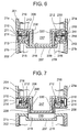
- FIG. 6 is an enlarged longitudinal sectional view showing a connecting part when an upper part and a base of the mobile telephone are engaged to each other.
- the engaging part 206 comprises an inner housing 208, which is fixed in the lower part of an upper case 21a and has claws 209, pressing parts 210 for causing the claws 209 to project and retreat.
- the inner housing 208 is substantially formed into a convex part which is fixed in the lower part of the upper case 21a so as to protrude substantially as a rectangle solid from the center of the lower surface of the upper part 201 (connecting surface with the base).
- the claws 209 are vertically disposed so as to protrude on both side faces of a short side of a protruding part 217 from the upper part of grooves 220.
- the grooves 220 are concavely disposed in a vertical direction at the center of the side faces of the short side of the protruding part 217.
- the claws 209 are elastically deformed by a pressing operation of pressing parts 210, which will be discussed later, and can be protruded and retreated from the side faces.
- the pressing parts 210 each comprises a pressing body 211, a snap ring 212 and a compression spring 213.
- the pressing bodies 211 are substantially formed into convex parts, each having a stick-like core beam 215 extended from an operating part 214, which is substantially formed into a rectangular solid.
- Grooves where the snap rings 212 are fit are each disposed at a prescribed position with a prescribed length, such that the operating parts 214 are flush with outer surfaces in a state in which the ends of the core beams 215 are in contact with the bases of the claws 209, and the core beams 215 are inserted to connecting holes 216 so as to freely slide.
- the connecting holes 216 are disposed on the lower part of both sides of the inner housing 208 and connect the bases of the claws 209 and the outside.
- the snap rings 212 are snap rings for shafts that include an E ring and a C ring, and the snap rings 212 are fit into the grooves formed around the pressing bodies 211 to prevent the pressing bodies 211 from falling.
- the compression springs 213 are loosely fit into the bases of the core beams 215 so as to press the lower part of both sides of the inner housing 208 and the operating part 214, and the compression springs 213 energize the operating parts 214 to the outside.
- the ends of the core beams 215 press the bases of the claws 209 to elastically deform the claws 209 protruding on the sides of the protruding part, and the claws 209 are stored in the grooves 220.
- the pressing bodies 211 are returned to prescribed positions by the compression springs 213 and the claws 209 simultaneously return to a state in which the claws 209 protrude on both sides, that is, their initial state.
- the engaged part 207 has a concave part 218, which is removably engaged to the protruding part 217 of the inner housing 208.
- the lower part of the concave part 218 is substantially formed into a concave part where a step 219 is concavely disposed for engaging the claws 209, and the engaged part 207 is fixed in the upper part of a base case 21b.
- an electric circuit for realizing known communication protocols (e.g., infrared communication and BLUETOOTH communication) is provided so as to have two-way communication between the upper terminal body 21 and the lower terminal body 22. Even when the upper terminal body 21 is separated from the lower terminal body 22, it is possible to access e-mail messages, the Internet and information on the liquid crystal display 204.
- known communication protocols e.g., infrared communication and BLUETOOTH communication
- the mobile telephone of the second embodiment configured similar to the first embodiment. That is, the upper part 201 is fit into the base 202 via the interlocking mechanism 203 such that the liquid crystal display 204 is positioned such that if the folding mobile telephone is closed, the liquid crystal display would not be viewable.
- FIG. 7 is an enlarged longitudinal sectional view showing a state in which the upper part and the base of the mobile telephone are separated from each other subsequently to FIG. 6.
- the operating parts 214 are pressed down, so that the ends of the core beams 215 press the bases of the claws 209 to elastically deform the claws 209 protruding on the sides of the protruding part 217, the claws 209 are stored in the grooves 211, and the engagement is released.
- the upper part 201 is removed upward, so that the upper part 201 is separated from the base 202.
- the upper part 201 is pressed to the base 202.
- the claws 209 are brought into contact with the inner wall of the concave part 218 and are bent so as to be stored in the grooves 211, and the upper part 201 is pressed as it is until the claws 209 reach steps 219.
- the claws 209 reach the steps 219, the claws 209 are engaged to the steps 219 and the upper part 201 is locked into the base 202.
- the liquid crystal display 204 can be viewed from the outside and the operating button group 205 (operating means) is exposed on the outer surface of the upper part 201.
- the operating button group 205 operating means
- FIG. 8 is a perspective view schematically showing that radio communication is performed while the upper part and the base of the mobile telephone are separated from each other.
- the mobile telephone of the second embodiment uses a radio system as communication means, the mobile telephone can be used while the upper part 201 is separated from the base 202.
- E-mail messages can be read or desired Internet sites can be viewed by using the small and lightweight upper part while the lower terminal body 22 is placed a short distance away, e.g., in a bag or under the table. This provides a mobile telephone which is quite excellent in portability.
- Wired connection may be arbitrarily made by using both of the interlocking mechanism and the connector
- wireless connection may be arbitrarily made by concavely providing the snap-in locking mechanism not protruding the outer surfaces of the upper part and the base, or another lock means may be arbitrarily used.
- the mechanical button group provided under the liquid crystal display is discussed as an example of operating means, any form is acceptable including a mechanical button group provided on the side of the upper part and a so-called touch panel on which a switch is integrated with a liquid crystal panel.
Landscapes
- Engineering & Computer Science (AREA)
- Signal Processing (AREA)
- Telephone Set Structure (AREA)
Abstract
Description
Claims (14)
- A portable terminal device, comprising:a first case unit comprising a first group of key buttons;a second case unit connected to said first case unit via a hinge;a third case unit comprising a display;a connecting means for connecting said second case unit to said third case unit; anda lock means for mounting and removing said third case unit from said second case unit.
- The portable terminal device as claimed in claim 1, wherein said connecting means electrically connects said second case unit to said third case unit.
- The portable terminal device as claimed in claim 2, wherein said lock means mounts said third case unit on said second case unit in a flipping manner.
- The device as claimed in claim 1, 2 or 3, wherein said third case unit comprises a second group of key buttons.
- The portable terminal device as claimed in claim 4, wherein said second group of key buttons is disposed on the same side of said third case unit as said display.
- The portable terminal device as claimed in claim 5, wherein both said display and said second group of key buttons are accessible when said third case unit is connected to said second case unit.
- The device as claimed in any one of claims 1 to 6, wherein said lock means is a snap-in lock mechanism included in said second case unit and said third case unit.
- The device as claimed in any one of claims 1 to 7, wherein said lock means is an interlocking mechanism provided in said second case unit and said third case unit.
- The portable terminal device as claimed in claim 8, wherein said interlocking mechanism comprises:an engaged part provided in a first connecting surface of said second case unit; andan engaging part which is provided in a second connecting surface of said third case unit and is removably engaged with said engaged part.
- The portable terminal device as claimed in claim 9, wherein said engaging part is configured such that said engaging part engaged to said engaged part is disengaged in response to a predetermined operation by an user, so that said second case unit and said third case unit are separated from each other.
- The device as claimed in any one of claims 1 to 10, wherein said connecting means comprises at least one electrical connector for making electrical connections between said second case unit and said third case unit.
- The device as claimed in any one of claims 1 to 10, wherein said connecting means is a radio part provided in said second case unit and said third case unit for making a wireless connection between said second case unit and said third case unit.
- The device as claimed in any one of claims 1 to 10, wherein said connecting means is an infrared part provided in said second case unit and said third case unit for making a wireless connection between said second case unit and said third case unit.
- The device as claimed in any one of claims 1 to 13, wherein said portable terminal device is a portable telephone.
Applications Claiming Priority (2)
| Application Number | Priority Date | Filing Date | Title |
|---|---|---|---|
| JP2001347168A JP2003152840A (en) | 2001-11-13 | 2001-11-13 | Mobile phone |
| JP2001347168 | 2001-11-13 |
Publications (3)
| Publication Number | Publication Date |
|---|---|
| EP1318650A2 true EP1318650A2 (en) | 2003-06-11 |
| EP1318650A3 EP1318650A3 (en) | 2003-06-18 |
| EP1318650B1 EP1318650B1 (en) | 2005-02-09 |
Family
ID=19160215
Family Applications (1)
| Application Number | Title | Priority Date | Filing Date |
|---|---|---|---|
| EP02024547A Expired - Lifetime EP1318650B1 (en) | 2001-11-13 | 2002-11-04 | Foldable phone with detachable display |
Country Status (5)
| Country | Link |
|---|---|
| US (1) | US7212845B2 (en) |
| EP (1) | EP1318650B1 (en) |
| JP (1) | JP2003152840A (en) |
| CN (1) | CN1190938C (en) |
| DE (1) | DE60202932T2 (en) |
Cited By (4)
| Publication number | Priority date | Publication date | Assignee | Title |
|---|---|---|---|---|
| WO2005053286A1 (en) * | 2003-11-20 | 2005-06-09 | Nokia Corporation | A communication apparatus having foldable and turnable housing members |
| EP1553012A1 (en) * | 2004-01-07 | 2005-07-13 | Campagnolo S.r.l. | Coupling of electrical devices for a bicycle |
| US7499074B2 (en) | 2003-12-26 | 2009-03-03 | Lg Electronics Inc | Mobile communication device with enhanced image communication capability |
| US9065997B2 (en) | 2004-07-27 | 2015-06-23 | Lg Electronics Inc. | Image signal processing apparatus and method thereof in mobile communications terminal |
Families Citing this family (101)
| Publication number | Priority date | Publication date | Assignee | Title |
|---|---|---|---|---|
| USD486132S1 (en) | 2002-08-05 | 2004-02-03 | Lg Electronics Inc. | Cellular phone |
| USD491905S1 (en) | 2002-08-05 | 2004-06-22 | Lg Electronics Inc. | Cellular phone |
| USD512053S1 (en) * | 2002-09-17 | 2005-11-29 | Kyoćera Wireless Corp. | Wireless communication device |
| USD488452S1 (en) | 2002-09-19 | 2004-04-13 | Lg Electronics Inc. | Mobile phone |
| USD488454S1 (en) | 2002-12-17 | 2004-04-13 | Lg Electronics Inc. | Mobile phone |
| USD496016S1 (en) | 2003-02-21 | 2004-09-14 | Sendo International, Ltd. | Mobile telephone |
| KR20040079203A (en) * | 2003-03-06 | 2004-09-14 | 삼성전자주식회사 | Portable communication device |
| USD488453S1 (en) | 2003-06-02 | 2004-04-13 | Inventec Appliances Corporation | Mobile communication device |
| USD498468S1 (en) | 2003-07-01 | 2004-11-16 | Lg Electronics Inc. | Mobile phone |
| USD495674S1 (en) | 2003-07-04 | 2004-09-07 | Lg Electronics Inc. | Mobile phone |
| USD496645S1 (en) | 2003-07-04 | 2004-09-28 | Lg Electronics Inc. | Mobile phone |
| USD496643S1 (en) | 2003-07-04 | 2004-09-28 | Lg Electronics Inc. | Mobile phone |
| USD496014S1 (en) | 2003-07-14 | 2004-09-14 | Motorola, Inc. | Communication device |
| USD504670S1 (en) * | 2003-07-14 | 2005-05-03 | Motorola, Inc. | Communication device |
| KR100594715B1 (en) * | 2003-08-08 | 2006-07-03 | 삼성전자주식회사 | Portable Information Processing System with Pivot Function |
| USD490793S1 (en) | 2003-08-19 | 2004-06-01 | Benq Corporation | Mobile phone |
| WO2005043865A1 (en) * | 2003-10-30 | 2005-05-12 | Vodafone K.K. | Mobile communication terminal apparatus, core module for mobile communication terminal apparatus, and function module for mobile communication terminal apparatus |
| USD515056S1 (en) * | 2003-11-13 | 2006-02-14 | Vodafone K.K. | Cell phone |
| USD522987S1 (en) * | 2003-11-13 | 2006-06-13 | Vodafone K.K. | Cell phone |
| USD515057S1 (en) * | 2003-11-13 | 2006-02-14 | Vodafone K.K. | Cell phone |
| USD524273S1 (en) * | 2003-11-13 | 2006-07-04 | Vodafone K.K. | Cell phone |
| USD492275S1 (en) | 2003-11-14 | 2004-06-29 | Benq Corporation | Folding mobile phone |
| KR100608727B1 (en) * | 2003-12-09 | 2006-08-04 | 엘지전자 주식회사 | Separate mobile terminal for video call and communication method thereof |
| USD507551S1 (en) * | 2003-12-11 | 2005-07-19 | Samsung Electronics Co., Ltd. | Portable telephone |
| TWI237983B (en) * | 2004-01-13 | 2005-08-11 | Benq Corp | Folding electronic device |
| KR20070120616A (en) * | 2004-01-19 | 2007-12-24 | 세이코 엡슨 가부시키가이샤 | Electronic device and wireless communication terminal |
| USD500480S1 (en) * | 2004-02-23 | 2005-01-04 | Motorola, Inc. | Housing for a communication device or similar articles |
| USD508035S1 (en) * | 2004-05-06 | 2005-08-02 | Samsung Electronics Co., Ltd. | Portable telephone |
| TWI239751B (en) * | 2004-05-28 | 2005-09-11 | Benq Corp | Foldable electronic device |
| KR101046032B1 (en) | 2004-05-29 | 2011-07-01 | 엘지전자 주식회사 | Detachable portable terminal capable of video communication |
| USD534530S1 (en) * | 2004-06-11 | 2007-01-02 | Nokia Corporation | Key button area for a handset |
| USD509496S1 (en) * | 2004-06-11 | 2005-09-13 | Robert J. Petcavich | Handheld wireless videoconferencing device |
| JP3821142B2 (en) * | 2004-07-01 | 2006-09-13 | セイコーエプソン株式会社 | Wireless communication terminal and internal wireless communication control method |
| USD537059S1 (en) * | 2004-11-05 | 2007-02-20 | Lg Electronics Inc. | Cellular phone |
| USD538772S1 (en) * | 2004-12-03 | 2007-03-20 | Lg Electronics Inc. | Cellular phone |
| USD518467S1 (en) * | 2005-01-03 | 2006-04-04 | Samsung Electronics Co., Ltd. | Cellular phone |
| USD541248S1 (en) * | 2005-01-14 | 2007-04-24 | Samsung Electronics Co., Ltd. | Mobile phone |
| USD560216S1 (en) | 2005-03-07 | 2008-01-22 | Omron Corporation | Portable telephone |
| USD544852S1 (en) * | 2005-03-07 | 2007-06-19 | Omron Corporation | Portable telephone |
| USD531155S1 (en) * | 2005-03-08 | 2006-10-31 | Lg Electronics Inc. | Mobile phone |
| USD521480S1 (en) * | 2005-03-09 | 2006-05-23 | Benq Corporation | Folding cell phone |
| USD540769S1 (en) * | 2005-03-10 | 2007-04-17 | Lg Electronics Inc. | Mobile phone |
| KR101139783B1 (en) * | 2005-03-14 | 2012-04-26 | 엘지전자 주식회사 | Mobile communication terminal with straight line style fpcb |
| ZAA200501278S (en) * | 2005-03-16 | 2005-12-06 | Microsoft Mobile Oy | Handset |
| JP4196963B2 (en) * | 2005-03-25 | 2008-12-17 | セイコーエプソン株式会社 | Electronic device and wireless communication terminal |
| USD546311S1 (en) * | 2005-04-15 | 2007-07-10 | Samsung Electronics Co., Ltd. | Mobile phone |
| USD530698S1 (en) * | 2005-04-27 | 2006-10-24 | Samsung Electronics Co., Ltd. | Mobile phone |
| USD566077S1 (en) * | 2005-04-27 | 2008-04-08 | Samsung Electronics Co., Ltd. | Mobile phone |
| USD536320S1 (en) * | 2005-05-04 | 2007-02-06 | Peter Michaels | Thin mobile telephone |
| USD594432S1 (en) * | 2005-05-26 | 2009-06-16 | Samsung Electronics Co., Ltd. | Portable telephone |
| USD552065S1 (en) * | 2005-06-13 | 2007-10-02 | Samsung Electronics Co., Ltd. | Mobile phone |
| USD551643S1 (en) * | 2005-06-15 | 2007-09-25 | Samsung Electronics Co., Ltd. | Mobile phone |
| USD551642S1 (en) * | 2005-06-15 | 2007-09-25 | Samsung Electronics Co., Ltd. | Mobile phone |
| USD549680S1 (en) * | 2005-06-22 | 2007-08-28 | Lg Electronics Inc. | Mobile phone |
| JP4584052B2 (en) * | 2005-06-28 | 2010-11-17 | 富士通株式会社 | Biaxial rotating parts and electronic equipment |
| USD552067S1 (en) * | 2005-07-15 | 2007-10-02 | Samsung Electronics Co., Ltd. | Mobile phone |
| USD560186S1 (en) * | 2005-09-15 | 2008-01-22 | Samsung Electronics Co., Ltd. | Mobile phone |
| TWI283982B (en) * | 2005-11-17 | 2007-07-11 | Benq Corp | Electronic device with movable and rotatable upper and lower housings |
| USD559816S1 (en) * | 2005-12-07 | 2008-01-15 | Samsung Electronics Co., Ltd. | Mobile phone |
| USD559815S1 (en) * | 2005-12-12 | 2008-01-15 | Samsung Electronics Co., Ltd. | Mobile phone |
| USD566082S1 (en) * | 2005-12-22 | 2008-04-08 | Samsung Electronics Co., Ltd. | Mobile phone |
| USD558170S1 (en) * | 2006-01-17 | 2007-12-25 | Cheng Uei Precision Industry Co., Ltd. | Foldable mobile phone |
| USD576132S1 (en) * | 2006-01-18 | 2008-09-02 | Lg Electronics Inc. | Mobile phone |
| USD559218S1 (en) * | 2006-02-06 | 2008-01-08 | Samsung Electronics Co., Ltd. | Mobile phone |
| USD559825S1 (en) * | 2006-03-07 | 2008-01-15 | Samsung Electronics Co., Ltd. | Mobile phone |
| USD554093S1 (en) * | 2006-03-20 | 2007-10-30 | Motorola Inc. | Communication device |
| KR100713480B1 (en) * | 2006-03-22 | 2007-05-02 | 삼성전자주식회사 | Hinge device of a portable terminal |
| USD561719S1 (en) * | 2006-03-24 | 2008-02-12 | Lg Electronics Inc. | Cellular phone |
| USD561151S1 (en) * | 2006-05-17 | 2008-02-05 | Samsung Electronics Co., Ltd. | Mobile phone |
| US7634300B2 (en) * | 2006-07-28 | 2009-12-15 | Sony Ericsson Mobile Communications Ab | Dual hinged display module for use in a mobile device |
| US20080026803A1 (en) * | 2006-07-28 | 2008-01-31 | Sony Ericsson Mobile Communications Ab | Detachable Housings for a Wireless Communication Device |
| USD561717S1 (en) * | 2006-08-03 | 2008-02-12 | Samsung Electronics Co., Ltd. | Mobile phone |
| USD561722S1 (en) * | 2006-11-29 | 2008-02-12 | Samsung Electronics Co., Ltd. | Mobile phone |
| USD561728S1 (en) * | 2006-12-14 | 2008-02-12 | Samsung Electronics Co., Ltd. | Portable phone |
| USD585406S1 (en) * | 2007-01-10 | 2009-01-27 | Samsung Electronics Co., Ltd. | Portable phone |
| USD578501S1 (en) * | 2007-07-26 | 2008-10-14 | Lg Electronics Inc. | Cellular phone |
| USD578499S1 (en) * | 2007-10-02 | 2008-10-14 | Samsung Electronics Co., Ltd. | Cellular phone |
| USD588571S1 (en) * | 2007-10-26 | 2009-03-17 | Panasonic Corporation | Mobile phone |
| USD586321S1 (en) * | 2007-12-06 | 2009-02-10 | Sony Ericsson Mobile Communications Ab | Mobile phone |
| USD583793S1 (en) * | 2008-02-04 | 2008-12-30 | Samsung Electronics Co., Ltd. | Mobile phone |
| USD616405S1 (en) * | 2008-06-18 | 2010-05-25 | Kyocera Wireless Corp. | Portable electronic device |
| USD595259S1 (en) * | 2008-10-02 | 2009-06-30 | Nokia Corporation | Handset |
| USD595258S1 (en) * | 2008-10-02 | 2009-06-30 | Nokia Corporation | Handset |
| JP4618374B2 (en) * | 2008-12-25 | 2011-01-26 | セイコーエプソン株式会社 | Wireless communication terminal |
| DE102009010413A1 (en) * | 2009-02-26 | 2010-09-02 | Deutsche Telekom Ag | System with mobile phone and attachable add-on modules |
| KR101587102B1 (en) * | 2009-03-02 | 2016-01-20 | 엘지전자 주식회사 | Mobile terminal |
| US8565829B2 (en) * | 2009-03-02 | 2013-10-22 | Lg Electronics Inc. | Mobile terminal with detachably coupled sub-device |
| JP5765224B2 (en) * | 2009-03-31 | 2015-08-19 | 日本電気株式会社 | PORTABLE TERMINAL DEVICE, ITS CONTROL PROGRAM, AND MULTI-DISPLAY SCREEN CONTROL METHOD |
| USD631451S1 (en) * | 2009-09-30 | 2011-01-25 | Samsung Electronics Co., Ltd. | Mobile phone |
| USD626931S1 (en) * | 2009-09-30 | 2010-11-09 | Samsung Electronics Co., Ltd. | Mobile phone |
| KR101824126B1 (en) * | 2010-05-14 | 2018-02-01 | 가부시키가이샤 한도오따이 에네루기 켄큐쇼 | Electronic apparatus and method for connecting electronic device |
| USD651582S1 (en) * | 2010-12-10 | 2012-01-03 | Samsung Electronics Co., Ltd. | Mobile phone |
| USD660271S1 (en) * | 2010-12-10 | 2012-05-22 | Samsung Electronics Co., Ltd. | Mobile phone |
| USD647873S1 (en) * | 2011-01-18 | 2011-11-01 | Lg Electronics Inc. | Cellular phone |
| EP3188458B1 (en) * | 2015-12-29 | 2018-09-12 | Lg Electronics Inc. | Mobile terminal |
| US20170192467A1 (en) * | 2016-01-02 | 2017-07-06 | Lenovo (Singapore) Pte. Ltd. | Hinge assemblies |
| WO2017126736A1 (en) * | 2016-01-22 | 2017-07-27 | 엘지전자(주) | Mobile terminal |
| KR101688169B1 (en) * | 2016-01-26 | 2017-01-02 | 엘지전자 주식회사 | Mobile terminal comprising a subdevice |
| WO2018113180A1 (en) * | 2016-12-19 | 2018-06-28 | 华为技术有限公司 | Terminal device, electronic device, and notebook computer |
| CN107269677B (en) * | 2017-07-06 | 2023-08-15 | 王宁光 | Hinge mechanism of folding display screen |
| CN107426369A (en) * | 2017-09-06 | 2017-12-01 | 金雅豪精密金属科技(深圳)股份有限公司 | Plate in mobile phone with segmented housing |
Family Cites Families (12)
| Publication number | Priority date | Publication date | Assignee | Title |
|---|---|---|---|---|
| JPH071460Y2 (en) | 1989-11-24 | 1995-01-18 | ザ・パック株式会社 | Wall protection plate |
| US5196991A (en) * | 1991-09-13 | 1993-03-23 | Hsieh La Fai | Portable computer having pivotable detachable cover with display |
| JPH06266472A (en) | 1993-03-12 | 1994-09-22 | Sharp Corp | Display device attachment / detachment mechanism |
| JP2595932B2 (en) * | 1994-05-18 | 1997-04-02 | 日本電気株式会社 | Portable radio |
| JP3737160B2 (en) * | 1995-03-31 | 2006-01-18 | 富士通株式会社 | Folding mobile phone hinge mechanism and folding mobile phone |
| JP3398675B2 (en) | 1996-06-12 | 2003-04-21 | 日本電気株式会社 | Mobile phone and notification control method using the same |
| JP3019013B2 (en) | 1996-11-21 | 2000-03-13 | 日本電気株式会社 | Portable communication device |
| JP3492562B2 (en) | 1996-11-21 | 2004-02-03 | 日本電気株式会社 | Portable communication device |
| US6115618A (en) * | 1998-02-24 | 2000-09-05 | Motorola, Inc. | Portable electronic device with removable display |
| US6542721B2 (en) * | 1999-10-11 | 2003-04-01 | Peter V. Boesen | Cellular telephone, personal digital assistant and pager unit |
| DE19950006C2 (en) * | 1999-10-18 | 2001-11-29 | Rfi Mobile Technologies Ag | System consisting of a portable computer and a connection station |
| US6549789B1 (en) * | 2000-04-28 | 2003-04-15 | Motorola Inc. | Portable electronic device with an adaptable user interface |
-
2001
- 2001-11-13 JP JP2001347168A patent/JP2003152840A/en active Pending
-
2002
- 2002-11-04 DE DE60202932T patent/DE60202932T2/en not_active Expired - Lifetime
- 2002-11-04 EP EP02024547A patent/EP1318650B1/en not_active Expired - Lifetime
- 2002-11-08 US US10/290,516 patent/US7212845B2/en not_active Expired - Lifetime
- 2002-11-13 CN CNB021584400A patent/CN1190938C/en not_active Expired - Fee Related
Cited By (6)
| Publication number | Priority date | Publication date | Assignee | Title |
|---|---|---|---|---|
| WO2005053286A1 (en) * | 2003-11-20 | 2005-06-09 | Nokia Corporation | A communication apparatus having foldable and turnable housing members |
| US7499074B2 (en) | 2003-12-26 | 2009-03-03 | Lg Electronics Inc | Mobile communication device with enhanced image communication capability |
| US8032177B2 (en) | 2003-12-26 | 2011-10-04 | Lg Electronics Inc. | Mobile communication device with enhanced image communication capability |
| US8115798B2 (en) | 2003-12-26 | 2012-02-14 | Lg Electronics Inc. | Mobile communication device with enhanced image communication capability |
| EP1553012A1 (en) * | 2004-01-07 | 2005-07-13 | Campagnolo S.r.l. | Coupling of electrical devices for a bicycle |
| US9065997B2 (en) | 2004-07-27 | 2015-06-23 | Lg Electronics Inc. | Image signal processing apparatus and method thereof in mobile communications terminal |
Also Published As
| Publication number | Publication date |
|---|---|
| US7212845B2 (en) | 2007-05-01 |
| HK1056067A1 (en) | 2004-01-30 |
| CN1190938C (en) | 2005-02-23 |
| CN1419364A (en) | 2003-05-21 |
| EP1318650A3 (en) | 2003-06-18 |
| DE60202932T2 (en) | 2005-07-07 |
| EP1318650B1 (en) | 2005-02-09 |
| DE60202932D1 (en) | 2005-03-17 |
| JP2003152840A (en) | 2003-05-23 |
| US20030092401A1 (en) | 2003-05-15 |
Similar Documents
| Publication | Publication Date | Title |
|---|---|---|
| US7212845B2 (en) | Portable terminal device capable of displaying information in a closed state | |
| JP3796222B2 (en) | Portable wireless terminal | |
| RU2328071C2 (en) | Portable terminal of combined type | |
| JP3628655B2 (en) | A portable digital terminal that integrates the functions of a portable information terminal and the function of a cellular phone. | |
| US6941618B2 (en) | Hinge device for portable wireless terminal | |
| JPWO2005020046A1 (en) | Electronics | |
| US7437185B2 (en) | Folder type mobile terminal | |
| CN101277321B (en) | Mobile terminal | |
| KR20050066671A (en) | Double rotation open/close apparatus for portable terminal | |
| JP2002218030A (en) | Folding portable terminal | |
| KR100747539B1 (en) | Dual screen mobile terminal | |
| JP4210288B2 (en) | Portable wireless terminal | |
| JP3852280B2 (en) | Portable communication device | |
| JP3492562B2 (en) | Portable communication device | |
| KR20030037286A (en) | Mobile phone having camera lens | |
| KR100264827B1 (en) | Structure for a flexible pcb of cellular telephone | |
| JP2008085705A (en) | Portable electronic devices | |
| HK1056067B (en) | Portable terminal device capable of displaying information in a closed state | |
| EP1843557B1 (en) | Hinge device for portable wireless terminal | |
| CN1787553B (en) | Mobile communication terminal | |
| KR200370668Y1 (en) | Mobile terminal of slide type movable the right and left | |
| JP2002368861A (en) | Mobile phone equipment | |
| JP2003273982A (en) | Mobile phone terminal and external display device | |
| KR100617738B1 (en) | Wireless terminal device with charger | |
| JP2002199075A (en) | Electronic unit with portable telephone holder |
Legal Events
| Date | Code | Title | Description |
|---|---|---|---|
| PUAI | Public reference made under article 153(3) epc to a published international application that has entered the european phase |
Free format text: ORIGINAL CODE: 0009012 |
|
| PUAL | Search report despatched |
Free format text: ORIGINAL CODE: 0009013 |
|
| AK | Designated contracting states |
Designated state(s): AT BE BG CH CY CZ DE DK EE ES FI FR GB GR IE IT LI LU MC NL PT SE SK TR |
|
| AX | Request for extension of the european patent |
Extension state: AL LT LV MK RO SI |
|
| AK | Designated contracting states |
Designated state(s): AT BE BG CH CY CZ DE DK EE ES FI FR GB GR IE IT LI LU MC NL PT SE SK TR |
|
| AX | Request for extension of the european patent |
Extension state: AL LT LV MK RO SI |
|
| 17P | Request for examination filed |
Effective date: 20030509 |
|
| 17Q | First examination report despatched |
Effective date: 20030813 |
|
| AKX | Designation fees paid |
Designated state(s): DE FR GB IT |
|
| GRAP | Despatch of communication of intention to grant a patent |
Free format text: ORIGINAL CODE: EPIDOSNIGR1 |
|
| GRAS | Grant fee paid |
Free format text: ORIGINAL CODE: EPIDOSNIGR3 |
|
| GRAA | (expected) grant |
Free format text: ORIGINAL CODE: 0009210 |
|
| AK | Designated contracting states |
Kind code of ref document: B1 Designated state(s): DE FR GB IT |
|
| REG | Reference to a national code |
Ref country code: GB Ref legal event code: FG4D |
|
| REF | Corresponds to: |
Ref document number: 60202932 Country of ref document: DE Date of ref document: 20050317 Kind code of ref document: P |
|
| PLBE | No opposition filed within time limit |
Free format text: ORIGINAL CODE: 0009261 |
|
| STAA | Information on the status of an ep patent application or granted ep patent |
Free format text: STATUS: NO OPPOSITION FILED WITHIN TIME LIMIT |
|
| ET | Fr: translation filed | ||
| 26N | No opposition filed |
Effective date: 20051110 |
|
| REG | Reference to a national code |
Ref country code: GB Ref legal event code: 732E Free format text: REGISTERED BETWEEN 20141023 AND 20141029 |
|
| REG | Reference to a national code |
Ref country code: FR Ref legal event code: TP Owner name: LENOVO INNOVATIONS LIMITED (HONG KONG), HK Effective date: 20141119 |
|
| PGFP | Annual fee paid to national office [announced via postgrant information from national office to epo] |
Ref country code: FR Payment date: 20141110 Year of fee payment: 13 |
|
| PGFP | Annual fee paid to national office [announced via postgrant information from national office to epo] |
Ref country code: IT Payment date: 20141110 Year of fee payment: 13 |
|
| PG25 | Lapsed in a contracting state [announced via postgrant information from national office to epo] |
Ref country code: IT Free format text: LAPSE BECAUSE OF NON-PAYMENT OF DUE FEES Effective date: 20151104 |
|
| REG | Reference to a national code |
Ref country code: FR Ref legal event code: ST Effective date: 20160729 |
|
| PG25 | Lapsed in a contracting state [announced via postgrant information from national office to epo] |
Ref country code: FR Free format text: LAPSE BECAUSE OF NON-PAYMENT OF DUE FEES Effective date: 20151130 |
|
| REG | Reference to a national code |
Ref country code: DE Ref legal event code: R082 Ref document number: 60202932 Country of ref document: DE Representative=s name: VOSSIUS & PARTNER PATENTANWAELTE RECHTSANWAELT, DE Ref country code: DE Ref legal event code: R081 Ref document number: 60202932 Country of ref document: DE Owner name: LENOVO INNOVATIONS LIMITED, HK Free format text: FORMER OWNER: NEC CORP., TOKYO, JP |
|
| PGFP | Annual fee paid to national office [announced via postgrant information from national office to epo] |
Ref country code: GB Payment date: 20181130 Year of fee payment: 17 |
|
| PGFP | Annual fee paid to national office [announced via postgrant information from national office to epo] |
Ref country code: DE Payment date: 20190131 Year of fee payment: 17 |
|
| REG | Reference to a national code |
Ref country code: DE Ref legal event code: R119 Ref document number: 60202932 Country of ref document: DE |
|
| GBPC | Gb: european patent ceased through non-payment of renewal fee |
Effective date: 20191104 |
|
| PG25 | Lapsed in a contracting state [announced via postgrant information from national office to epo] |
Ref country code: GB Free format text: LAPSE BECAUSE OF NON-PAYMENT OF DUE FEES Effective date: 20191104 Ref country code: DE Free format text: LAPSE BECAUSE OF NON-PAYMENT OF DUE FEES Effective date: 20200603 |