EP1318571A2 - Electric connector with cable holding mechanism - Google Patents
Electric connector with cable holding mechanism Download PDFInfo
- Publication number
- EP1318571A2 EP1318571A2 EP02027152A EP02027152A EP1318571A2 EP 1318571 A2 EP1318571 A2 EP 1318571A2 EP 02027152 A EP02027152 A EP 02027152A EP 02027152 A EP02027152 A EP 02027152A EP 1318571 A2 EP1318571 A2 EP 1318571A2
- Authority
- EP
- European Patent Office
- Prior art keywords
- cable
- piece
- holding mechanism
- convex projections
- strip
- Prior art date
- Legal status (The legal status is an assumption and is not a legal conclusion. Google has not performed a legal analysis and makes no representation as to the accuracy of the status listed.)
- Withdrawn
Links
Images



Classifications
-
- H—ELECTRICITY
- H01—ELECTRIC ELEMENTS
- H01R—ELECTRICALLY-CONDUCTIVE CONNECTIONS; STRUCTURAL ASSOCIATIONS OF A PLURALITY OF MUTUALLY-INSULATED ELECTRICAL CONNECTING ELEMENTS; COUPLING DEVICES; CURRENT COLLECTORS
- H01R13/00—Details of coupling devices of the kinds covered by groups H01R12/70 or H01R24/00 - H01R33/00
- H01R13/58—Means for relieving strain on wire connection, e.g. cord grip, for avoiding loosening of connections between wires and terminals within a coupling device terminating a cable
-
- H—ELECTRICITY
- H01—ELECTRIC ELEMENTS
- H01R—ELECTRICALLY-CONDUCTIVE CONNECTIONS; STRUCTURAL ASSOCIATIONS OF A PLURALITY OF MUTUALLY-INSULATED ELECTRICAL CONNECTING ELEMENTS; COUPLING DEVICES; CURRENT COLLECTORS
- H01R13/00—Details of coupling devices of the kinds covered by groups H01R12/70 or H01R24/00 - H01R33/00
- H01R13/58—Means for relieving strain on wire connection, e.g. cord grip, for avoiding loosening of connections between wires and terminals within a coupling device terminating a cable
- H01R13/5804—Means for relieving strain on wire connection, e.g. cord grip, for avoiding loosening of connections between wires and terminals within a coupling device terminating a cable comprising a separate cable clamping part
- H01R13/5816—Means for relieving strain on wire connection, e.g. cord grip, for avoiding loosening of connections between wires and terminals within a coupling device terminating a cable comprising a separate cable clamping part for cables passing through an aperture in a housing wall, the separate part being captured between cable and contour of aperture
-
- H—ELECTRICITY
- H01—ELECTRIC ELEMENTS
- H01R—ELECTRICALLY-CONDUCTIVE CONNECTIONS; STRUCTURAL ASSOCIATIONS OF A PLURALITY OF MUTUALLY-INSULATED ELECTRICAL CONNECTING ELEMENTS; COUPLING DEVICES; CURRENT COLLECTORS
- H01R13/00—Details of coupling devices of the kinds covered by groups H01R12/70 or H01R24/00 - H01R33/00
- H01R13/58—Means for relieving strain on wire connection, e.g. cord grip, for avoiding loosening of connections between wires and terminals within a coupling device terminating a cable
- H01R13/5833—Means for relieving strain on wire connection, e.g. cord grip, for avoiding loosening of connections between wires and terminals within a coupling device terminating a cable the cable being forced in a tortuous or curved path, e.g. knots in cable
-
- Y—GENERAL TAGGING OF NEW TECHNOLOGICAL DEVELOPMENTS; GENERAL TAGGING OF CROSS-SECTIONAL TECHNOLOGIES SPANNING OVER SEVERAL SECTIONS OF THE IPC; TECHNICAL SUBJECTS COVERED BY FORMER USPC CROSS-REFERENCE ART COLLECTIONS [XRACs] AND DIGESTS
- Y10—TECHNICAL SUBJECTS COVERED BY FORMER USPC
- Y10S—TECHNICAL SUBJECTS COVERED BY FORMER USPC CROSS-REFERENCE ART COLLECTIONS [XRACs] AND DIGESTS
- Y10S439/00—Electrical connectors
- Y10S439/901—Connector hood or shell
- Y10S439/902—Angularly disposed contact and conductor
Definitions
- the invention relates to an electric connector with a cable holding mechanism, particularly to an electric connector with a cable holding mechanism provided with a cable bundling piece for bundling wires.
- the first method is, for example, disclosed in JU-A 63-3076 and the second method is, for example, disclosed in JP-A 11-329574.
- An electric connector as disclosed in JU-A 63-3076 comprises, as shown in Fig. 7, a block 100 having a contact which is inserted into or removed from the block 100, and a contact hood 101 for covering a connection part between the contact and a cable when the contact hood 101 is retained by the block 100.
- a base table 102 is formed on the contact hood 101 for attaching a cable clamp 104 at a position in the vicinity of a cable drawing opening, and the cable clamp 104 fixed to the base table by screws 103 so as to clamp an outer periphery of a cable 105 so that a tensile force is not applied to the connection part.
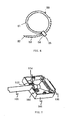
- An electric connector with a cable holding piece as disclosed in JP-A 11-329574 comprises, as shown in Figs. 8(A) and 8(B), a pair of holding plates 110A, 110B, a narrow width part 111 for connecting between the holding plates, and a clamp 112 for bundling wires which are drawn out from a back face of a connector housing provided at one of the holding plates.
- the narrow width part 111 is inserted into an insertion groove 113 provided in the connector housing, so that the narrow width part 111 is retained by a slot part and is prevented from being removed therefrom.
- each wire is bent along the back face of the connector housing, then it is arranged backward, and hence a tensile force does not directly act on terminals provided inside the connector housing even if the tensile force is applied to each wire.
- the invention has been developed to solve the problems described above and an object of the invention is to provide an electric connector with a cable holding mechanism for simplifying the structure of the cable holding mechanism without using a special cable holding piece, reducing the number of man-hours by simplifying work for attaching the cable holding mechanism to the connector housing, and reducing a manufacturing cost.
- the object of the invention can be achieved by the following means and structure.
- the electric connector with a cable holding mechanism comprises a plug proper having a plurality of connector terminals fitted therein at an inner opening thereof and a cable drawing face from which wires connected to the connector terminals is drawn out, a cover cap to be fitted to the plug proper in a state where the cable drawing face is covered therewith and the cable is drawn outside, and a cable holding mechanism formed on wall faces of the cover cap, characterized in that the cable holding mechanism is made up of grooves each having a width in which a flexible strip-like piece of a cable bundling piece is inserted at a position in the vicinity of a cable drawing opening of the cover cap.
- the grooves are formed to have a width in which the strip-like piece of the cable bundling piece is inserted into the wall faces of the cover cap, and the strip-like piece of the cable bundling piece is inserted into and fixedly attached to the grooves.
- the shape of the grooves is simplified so that the fabrication of the grooves is easy.
- the cable bundling piece bundles a plurality of wires and comprises the flexible strip-like piece having a given width and thickness, ratches at one face thereof, and a retainer provided at the tip end of the flexible strip-like piece for engaging with one of the ratches.
- the grooves are made up of convex projections which are wider than a width of the strip-like piece of the cable bundling piece and are arranged in parallel with each other, and a height of the convex projections is approximately the same as a thickness of the strip-like piece.
- the grooves are made up of two inner projections which are wider than a width of the strip-like piece of the cable bundling piece and are arranged in parallel with each other, and outer convex projections provided in the vicinity of the outside of the two inner convex projections, wherein a height of the respective convex projections is approximately the same as a thickness of the strip-like piece, and the tip end of the outer convex projections is longer than that of the inner convex projections.
- the respective convex projections are provided on opposite wall faces of the cover cap, and the strip-like piece of the wire bundling piece is engaged and inserted between the opposite inner convex projections.
- these grooves are made up of convex projections, the shape thereof is simplified and is formed with ease. Further, since the cable holding mechanism can be fixedly attached to the connector housing by merely pushing the strip-like piece of the wire bundling piece between the convex projections, it can be fitted into the connector housing without using tools or the like with ease.
- Figs. 1(A) and 1(B) show a plug for constituting an electric connector of the invention and a receptacle connected to the plug, wherein Fig. 1(A) is a perspective view showing a state of connection between the plug and the receptacle, and Fig. 1(B) is a perspective view showing a state of disconnection between the plug and the receptacle.
- Figs. 2(A) to 2 (C) show components of the electric connector which are separated from each other in a state of disconnection between the plug and the receptacle, wherein Fig. 2(A) is a perspective view of the receptacle, Fig.
- FIG. 2(B) is a perspective view of the plug from which a cover is detached
- Fig. 2(C) is a perspective view of a plug cover
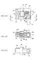
- Figs. 3(A) and 3(B) show the plug wherein Fig. 3(A) is a side view of the plug as seen from arrows A-A in Fig. 2(B), and Fig. 3(B) is a side view of the plug as seen from arrows B-B in Fig. 2(B).
- an electric connector 10 comprises a plug-type connector (hereinafter referred to merely as plug) 20 and a receptacle-type connector (hereinafter referred to as merely receptacle) 90 removably connected to the plug 20.
- the plug 20 includes a plug proper 30, connector terminals fitted in the plug proper 30, and a cover cap 60 removably fitted on the plug 20 so as to cover a connection part between the connector terminals and lead wires.
- the plug proper 30 is made up of a housing in flat block shape housing and comprises upper and lower walls 31a, 31b, left and right sidewalls 31c, 31d, a flange 35 projecting externally from a peripheral wall surface of these sidewalls, and an opening 32 through which the connector terminals are fitted in the housing, and it is formed of an insulating synthetic resin material.
- the flange 35 has projecting chamber 35a to 35e at both end portions of the upper and lower wall faces 31a, 31b and a substantially central portion of the left sidewall 31c, each having walls erected from each wall face thereof, wherein the erected wall are formed in a position where the erected wall ends are flush with each other. Further, these projecting chambers 35a to 35e are formed openings, and retainer protrusions 36a to 36e are formed at substantially the central portions of these openings. The retainer protrusions 36a to 36e formed inside the projecting chambers 35a to 35e are engaged with attachment ports of a cover cap 60, described later, to fixedly attach the cover cap 60 thereto.
- the plug proper 30 is divided, at front end of the flange 35 as the boundary, into a front housing, and a back housing.
- the front housing has the upper and lower walls 31a, 31b and the left and right sidewalls 31c, 31d, and an external shape thereof is substantially the same as the shape of an opening of the receptacle, described later, in which the front housing is inserted.
- Strip-like elastic engagement arms 37a, 37b which are bent back from the tip end of the opening 32 and extended horizontally are formed on the upper wall face 31a, and the tip ends of the elastic engagement arms 37a, 37b are connected to each other at a presser piece 37.
- Engagement pawls 38a, 38b are provided on the elastic engagement arms 37a, 37b at a center part of length of each of the strip-like elastic engagement arms 37a, 37b.
- the elastic engagement arms 37a, 37b are structured such that when the plug 20 is connected to the receptacle 90, engagement pawls 38a, 38b of the elastic engagement arms 37a, 37b enter concaves of the receptacle 90 (not shown) so that the plug 20 is coupled with the receptacle 90.
- the presser piece 37 is pressed downward by a finger so as to release the engagement between the engagement pawls 38a, 38b and the concaves of the receptacle 90, thereby releasing the coupling between the receptacle 90 and the plug 20.
- the opening 32 is provided in the front housing through which a plurality of connector terminals are fitted in the housing, and it links with a space part of the back housing.
- a deck 33 is provided in the opening 32 at a approximately central part thereof and extends widthwise and a plurality of grooves are formed on the upper face of the deck 33 through which connector terminals are fitted in the opening 32.
- the lower face of the deck 33 is partitioned by a plurality of spaced walls and different kinds of connector terminals 50a to 50n, 51a to 51n are fitted in chambers formed by the grooves and partition walls.
- the back housing is structured that an outer wall of the opening 32 of the front housing projects from the flange 35 to a back wall end, and insertion holes in which the connector terminals are inserted and a cable drawing face through which lead wires connected to each connector terminal are formed in the space part linking with the opening 32.
- a pair of protruding pieces 39, 40 extended from the left and right sidewalls 31c, 31d of the front housing are provided in the back housing wherein one protruding piece 39 is formed narrower while the other protruding piece 40 is formed wider.
- a guide groove 39a is provided on the central portion of the narrow protruding piece 39 outside and extended axially. As shown in Fig.
- the tip end of the wide protruding piece 40 is formed in a circulararc concave shape in which an outer shape of the cable is engaged and has guide protrusions 40a, 40b which extend axially while providing steps at both ends thereof in a width direction.
- the interior of the back housing is partitioned by a plurality of spaced walls, and chambers are formed by the grooves and spaced walls, wherein different kinds of connection terminals are fitted in these grooves and chambers.
- These openings are linked with the opening of the front housing and are connected to terminals to be fitted in the front housing.
- the receptacle 90 to be coupled with the plug 20 is made up of a housing in flat block shape and comprises upper and lower walls and left and right sidewalls, a flange protruding externally from these peripheral walls, elastic retainer arms provided at both sidewalls for engaging an attachment port of a panel (only one retainer arm 95b is shown in Fig. 1(B)), and an opening through which the connector terminals are fitted in the housing.
- the opening is formed to have approximately the same shape as the shape of the opening of the plug 20, through which the plug 20 is inserted, and an opening linked with this opening is formed at the side opposite to the opening, namely, a side opposite to the connection direction of the plug.
- connection pins 93 which are removably connected to other connectors (not shown) are embedded into these openings, and a plurality of chambers 94, through which terminals with lead wires (not shown) are fitted therein, are formed in these openings.
- Figs. 4(A) to 4 (C) show a cover cap, wherein Fig. 4(A) is a plan view, Fig. 4(B) is a front view of the cover cap as seen from arrows A-A in Fig. 4(A), and Fig. 4 (C) is a side view of the cover cap as seen from arrows B-B in Fig. 4(A).
- the cover cap 60 is provided to be removably fitted on the plug proper in a state where it covers a lead wire drawing face connected to the connector terminals while a cable is drawn outside, and it is made up of a flat box which is opened at a side through which the cover cap 60 is fitted on the plug proper 30 and a side through which the cable is drawn out.
- This box body is closed at peripheral sidewalls 61c, 61d, and is opened at the sidewall 61e through which the cable is drawn out and at a sidewall 61f through which the cover cap 60 is fitted on the plug proper 30.
- An opening 62 of the sidewall 61e is substantially formed of a U-shaped groove. As shown in Figs.
- grooves 62a, 62b (one of the grooves, the lower groove 62b is disclosed in Fig. 2(C)) to be engaged with the guide protrusions 40a, 40b are formed on end faces of the U-shaped groove 62, and an opening through which the cable can be inserted between itself and the tip end of the protruding piece 40, namely, sidewall 40 when the cover cap 60 is fitted on the plug proper 30 is formed at the innermost part of the groove.
- Retainer protrusions 63a to 63e are formed at four corners of the opened sidewall 61f and the tip end of one sidewall 61d, and retainer holes 64a to 64e are formed on the retainer protrusions 63a to 63e.
- the retainer holes 64a, 64b, are shown in Fig. 4(A) and the retainer hole 64e is shown in Fig. 4 (C) while the remaining retainer holes 64c, 64d are omitted in illustration.
- the cover cap 60 has convex projections 65, 66 disposed in the vicinity of the opening 62 and provided on upper and lower inner wall faces 61a, 61b in which the wire is retained (see Fig. 4(B)).
- the convex projections 65, 66 formed on the upper and lower inner wall faces 61a, 61b comprise four convex projections 65a to 65d, 66a to 66d in which two protrusions are paired while they are substantially in parallel with the sidewall 61e. Intervals between the inner convex projections 65a, 65b on the upper wall face and the inner convex projections 66a, 66b on the lower wall face are slightly wider than a width of a cable stopper, described later.
- Each height of the convex projections 65a, 65b and 66a, 66b, that is, an interval between the inner convex projections 65a, 65b of the upper wall face and the inner convex projections 66a, 66b of the lower wall face are set such that the cable stopper is inserted into the interval and is set at a height where the cable stopper is retained thereby.
- outer convex projections 65c, 65d are formed at positions in the vicinity of the inner convex projections 65a, 65b while the outer convex projections 66c, 66d are formed at positions in the vicinity of the inner convex projections 66a, 66b, wherein the height of the outer convex projections is substantially the same as that of the inner convex projections.
- Each tip end of the inner and outer convex projections provided on the upper and lower wall inner faces is configured that each tip end of the outer convex projections 65c, 65d and 66c, 66d is extended to be longer than that of the inner convex projections 65a, 65b and 66a, 66b.
- each tip end of the outer convex projections is extended to be slightly longer than that of the inner convex projections, when the cable stopper is inserted from the tip end of the convex projections, the width of the outer convex projections functions as a guide of the cable stopper relative to the inner convex projections, simplifing operation at the narrow spot.
- the convex projections are made up of the inner and outer convex projections, they may be made up of only the inner convex projections while the outer convex projections are dispensed with. Further, although the convex projections are formed on both the upper and lower wall faces, they may be formed on either the upper or lower wall face. Needless to say, such modification will entail modification in the shape of the convex projections according to the shape of the cable stopper. Further, the cable stopper is not only inserted from the tip end of the convex projections but also inserted from above and fixedly attached to the convex projections by such modification.
- the cover cap set forth above is fitted on the plug 20, it is applicable to the receptacle.
- the receptacle in this case is different from the type depicted by 90 shown in Fig. 1(B), wherein the connection pins 93 are changed to connector terminals with lead wires and a multiple-wire cable is used.
- the cover cap 60 set forth above is made up of a flat box, the shape thereof is not limited thereto, and hence they may have any optional shape such as square, round, or the like.
- the opening through which the wires or a multi-wire cable is drawn out may be provided at a rear wall confronting the plug proper but not provided at the side wall in the vicinity of the plug proper.
- both ends of two inner convex projections may form inclined outward so as to insert the cable stopper from both ends in the longitudinal direction, facilitating the insertion of the cable stopper.
- outer convex projections may be also formed like the aforesaid inner convex projections, and the tip end of the inner and outer convex projections may be formed such that the outer convex projections are slightly longer than the inner convex projections at tip ends thereof.
- the cable 70 is structured such that it includes a multi-wire cable and has been already known and has a plurality of lead wires 71a to 71i therein, wherein these lead wires are covered with a sheath.
- a cable stopper 80 is fastened to the sheath in the vicinity of the portion where the sheath of the cable 70 is stripped off.
- a cable bundling piece made of synthetic resin and is easily available on a market (see Fig. 6) is used as the cable stopper 80.
- the structure of the cable stopper 80 is configured such that it is formed of a flexible strip-like piece 81 normally having a given width and thickness with a square frame-like retainer 85 at the tip end thereof, and having a plurality of ratches 83 along half length to the tip end 82 on one surface thereof.
- the retainer 85 can be inserted into the strip-like piece 81 and a hook 84 is formed to be flexible and deformable at the opening edge of the retainer 85 for removably retaining one of the ratches 83.
- Fig. 5(A) shows a state where the multi-wire cable is fitted on the plug, and it is a plan view of a cover cap a part of which is broken
- Fig. 5(B) is a sectional view taken along arrows A-A in Fig. 5(A)
- Fig. 5(C) is a side view as seen from arrows B-B in Fig. 5(A).
- the sheath of the multi-wire cable 70 at the tip end thereof is stripped off to separate the lead wires into independent lead wires, wherein respective connector terminals (depicted by 50i, 51i in Fig. 5(B)) are connected to respective tip ends of the lead wires.
- the strip-like piece 81 of the cable stopper 80 (hereinafter referred to as cable bundling piece 80) is turned around the periphery of the sheath in the vicinity of the portion where the sheath of the multi-wire cable 70 is stripped off, and the tip end 82 of the strip-like piece 81 is inserted into the opening of the retainer 85 and fastened to the periphery of the sheath.
- the strip-like piece which is extended from the retainer 85 is cut so as to fix the cable bundling piece 80 to the multi-wire cable 70.
- a diameter of the outer periphery of the multi-wire cable 70 to which the cable bundling piece 80 is fixed increases at a width portion of the strip-like piece 81 by the thickness thereof.
- the increased diameter of the multi-wire cable 70 namely, the thicker portion of the multi-wire cable 70 is utilized as the cable stopper. That is, the retainer 85 is fastened to the sheath of the multi-wire cable 70 so as to direct towards the plug proper 30, and a loop-shaped portion of the strip-like piece 81 is pressed into the convex projections.
- the outer convex projections 65c, 65d and 66c, 66d Since the tip end of the outer convex projections 65c, 65d and 66c, 66d is extended to be longer than that of the inner convex projections 65a, 65b and 66a, 66b, the outer convex projections 65c, 65d and 66c, 66d function as a guide of the strip-like piece 81 and the strip-like piece 81 are simply pushed between the inner convex projections 65a, 65b and 66a, 66b, so that the loop-shaped portion of the strip-like piece 81 is fixed between the inner convex projections 65a, 65b and 66a, 66b of the cover cap 60.
- the multi-wire cable 70 is fixedly attached to the cover cap 60, and the connector terminals 50, 51 connected to the multi-wire cable 70 are fitted in the opening of the plug proper 30, then the retainer protrusions 63a to 63e of the cover cap 60 are inserted into the chamber 35a to 35e.
- the retainer holes 64a to 64e of the retainer protrusions 63a to 63e are engaged with the retainer projections 36a to 36e of the chambers 35a to 35e so that the cover cap 60 is fixedly attached to the plug proper 30.
- the cover cap 60 may be fixedly attached to the multi-wire cable 70 and it may be fitted on the plug proper 30 after the connector terminals 50, 51 are fitted in the opening of the plug proper 30.
- the structure of the cable holding mechanism can be simplified without using a special cable holding piece, the operation of attaching the cable holding mechanism to a connector housing is simplified, thereby reducing the number of man-hours, and also reducing a manufacturing cost.
Landscapes
- Details Of Connecting Devices For Male And Female Coupling (AREA)
- Connector Housings Or Holding Contact Members (AREA)
Abstract
Description
Claims (5)
- An electric connector with a cable holding mechanism comprising:wherein the cable holding mechanism is made up of grooves(65a-65b, 66a-66b) each having a width in which a flexible strip-like piece(81) of a cable bundling piece is inserted at a position in the vicinity of a cable drawing opening of the cover cap.a plug proper (30) having a plurality of connector terminals(50,51) fitted therein at an inner opening thereof and a cable drawing face from which wires (71) connected to the connector terminals is drawn out;a cover cap(60) to be fitted to the plug proper in a state where the cable drawing face is covered therewith and the cable(70) is drawn outside; anda cable holding mechanism formed on a wall face of the cover cap;
- The electric connector with a cable holding mechanism according to Claim 1, wherein the cable bundling piece bundles a plurality of wires(71) and comprises the flexible strip-like piece(81) having a given width and thickness, ratches (83) at one face thereof, and a retainer(85) provided at the tip end of the strip-like piece for engaging with one of the ratches.
- The electric connector with a cable holding mechanism according to Claim 1, wherein the grooves are made up of convex projections which are wider than a width of the strip-like piece of the cable bundling piece (81) and are arranged in parallel with each other, and a height of the convex projections is the same as a thickness of the strip-like piece.
- The electric connector with a cable holding mechanism according to Claim 1, wherein the grooves are made up of two inner projections(65a,65b, 66a, 66b) which are wider than a width of the strip-like piece of the cable bundling piece and are arranged in parallel with each other, and outer convex projections(65c, 65d, 66c, 66d) provided in the vicinity of the outside of the two inner convex projections, wherein a height of the respective convex projections is the same as a thickness of the strip-like piece, and the outer convex projections are longer than the inner convex projections at tip ends thereof.
- The electric connector with a cable holding mechanism according to Claim 3, wherein the respective convex projections are provided on upper and lawer wall faces of the cover cap, opposite to each other, and the strip-like piece of the cable bundling piece is engaged and inserted between the opposite inner convex projections.
Applications Claiming Priority (2)
| Application Number | Priority Date | Filing Date | Title |
|---|---|---|---|
| JP2001373447A JP2003173843A (en) | 2001-12-06 | 2001-12-06 | Electrical connector with wire retention mechanism |
| JP2001373447 | 2001-12-06 |
Publications (2)
| Publication Number | Publication Date |
|---|---|
| EP1318571A2 true EP1318571A2 (en) | 2003-06-11 |
| EP1318571A3 EP1318571A3 (en) | 2004-05-06 |
Family
ID=19182165
Family Applications (1)
| Application Number | Title | Priority Date | Filing Date |
|---|---|---|---|
| EP02027152A Withdrawn EP1318571A3 (en) | 2001-12-06 | 2002-12-04 | Electric connector with cable holding mechanism |
Country Status (6)
| Country | Link |
|---|---|
| US (1) | US6824420B2 (en) |
| EP (1) | EP1318571A3 (en) |
| JP (1) | JP2003173843A (en) |
| KR (1) | KR20030047724A (en) |
| CN (1) | CN1423372A (en) |
| TW (1) | TWI251962B (en) |
Families Citing this family (25)
| Publication number | Priority date | Publication date | Assignee | Title |
|---|---|---|---|---|
| JP2004288545A (en) * | 2003-03-24 | 2004-10-14 | Yazaki Corp | Connector protector |
| JP2006031974A (en) * | 2004-07-12 | 2006-02-02 | Tyco Electronics Amp Kk | Connector with wire cover and wire cover |
| JP4520315B2 (en) * | 2005-01-21 | 2010-08-04 | タイコエレクトロニクスジャパン合同会社 | Wire cover for connector |
| JP5012287B2 (en) * | 2007-07-27 | 2012-08-29 | 住友電装株式会社 | connector |
| US7758389B2 (en) * | 2008-01-25 | 2010-07-20 | Tyco Electronics Corporation | Connector assembly having a movable plug |
| JP5588773B2 (en) * | 2010-07-28 | 2014-09-10 | タイコエレクトロニクスジャパン合同会社 | Wire cover, electrical connector |
| JP5646974B2 (en) * | 2010-12-02 | 2014-12-24 | 日本圧着端子製造株式会社 | Electrical connector |
| JP2012119240A (en) * | 2010-12-02 | 2012-06-21 | Jst Mfg Co Ltd | Electric connector |
| JP5598384B2 (en) * | 2011-03-04 | 2014-10-01 | 住友電装株式会社 | connector |
| US9820839B2 (en) | 2012-04-10 | 2017-11-21 | Ethicon, Inc. | Single plane tissue repair patch having a locating structure |
| US9820837B2 (en) | 2012-04-10 | 2017-11-21 | Ethicon, Inc. | Single plane tissue repair patch |
| US9820838B2 (en) | 2012-04-10 | 2017-11-21 | Ethicon, Inc. | Single plane tissue repair patch |
| JP6191915B2 (en) * | 2013-10-29 | 2017-09-06 | 住友電装株式会社 | connector |
| DE102013225449A1 (en) * | 2013-12-10 | 2015-07-16 | Continental Automotive Gmbh | plug |
| CN103767555A (en) * | 2014-01-24 | 2014-05-07 | 广东福尔电子有限公司 | Heat insulation plate of electric rice cooker |
| DE102016108621B4 (en) * | 2016-05-10 | 2018-01-25 | Lisa Dräxlmaier GmbH | Connector housing and connectors |
| US9929496B1 (en) * | 2016-12-20 | 2018-03-27 | Schneider Electric USA, Inc. | Rectilinear communications connector with selectable cable outlet positions for confined spaces |
| JP6840583B2 (en) * | 2017-03-16 | 2021-03-10 | モレックス エルエルシー | Connector assembly and connector cover |
| JP7042580B2 (en) * | 2017-09-22 | 2022-03-28 | 古河電気工業株式会社 | Connector, housing, cover body, and wire harness with connector |
| DE102018127231B3 (en) * | 2018-10-31 | 2020-03-26 | Phoenix Contact Gmbh & Co. Kg | Connector device with at least one fixing part for providing a strain relief or jacket fixation |
| JP7219464B2 (en) * | 2019-04-26 | 2023-02-08 | 日本圧着端子製造株式会社 | electrical connector |
| JP7274127B2 (en) * | 2019-11-07 | 2023-05-16 | 株式会社オートネットワーク技術研究所 | connector |
| TWI729616B (en) * | 2019-12-10 | 2021-06-01 | 台達電子工業股份有限公司 | Power plug |
| JP7268083B2 (en) * | 2021-05-13 | 2023-05-02 | 矢崎総業株式会社 | protector and wire harness |
| US11923636B2 (en) * | 2021-09-10 | 2024-03-05 | Turck Inc. | Cable connector, cable connector arrangement and d-sub type cable connector |
Family Cites Families (10)
| Publication number | Priority date | Publication date | Assignee | Title |
|---|---|---|---|---|
| US3794960A (en) * | 1972-11-30 | 1974-02-26 | Itt | Junction shell |
| US3936129A (en) * | 1974-09-16 | 1976-02-03 | Western Electric Company, Inc. | Molded plastic hood assembly for a cable connector plug |
| US4035051A (en) * | 1976-10-19 | 1977-07-12 | Western Electric Company, Inc. | Adjustable molded hood assembly for a cable connector plug |
| US4722580A (en) * | 1981-03-02 | 1988-02-02 | Amp Incorporated | Two way cover assembly |
| US4842549A (en) * | 1987-04-16 | 1989-06-27 | Amp Incorporated | Dual diameter cable strain relief |
| US4842547A (en) * | 1988-05-19 | 1989-06-27 | Amp Incorporated | Staple cable strain relief |
| JPH07118348B2 (en) * | 1990-07-04 | 1995-12-18 | 英朗 茂治 | Cable retention device |
| US5389006A (en) * | 1993-08-13 | 1995-02-14 | Burndy Corporation | Lightweight entertainment connector |
| US6139355A (en) * | 1998-05-18 | 2000-10-31 | The Whitaker Corporation | Cover and strain relief for a cable assembly |
| TW395587U (en) * | 1998-12-31 | 2000-06-21 | Hon Hai Prec Ind Co Ltd | Cable connector assembly |
-
2001
- 2001-12-06 JP JP2001373447A patent/JP2003173843A/en active Pending
-
2002
- 2002-10-31 KR KR1020020067108A patent/KR20030047724A/en not_active Withdrawn
- 2002-12-04 CN CN02153888A patent/CN1423372A/en active Pending
- 2002-12-04 EP EP02027152A patent/EP1318571A3/en not_active Withdrawn
- 2002-12-04 US US10/309,111 patent/US6824420B2/en not_active Expired - Lifetime
- 2002-12-05 TW TW091135233A patent/TWI251962B/en not_active IP Right Cessation
Also Published As
| Publication number | Publication date |
|---|---|
| US20030109169A1 (en) | 2003-06-12 |
| CN1423372A (en) | 2003-06-11 |
| JP2003173843A (en) | 2003-06-20 |
| TWI251962B (en) | 2006-03-21 |
| US6824420B2 (en) | 2004-11-30 |
| KR20030047724A (en) | 2003-06-18 |
| EP1318571A3 (en) | 2004-05-06 |
| TW200301029A (en) | 2003-06-16 |
Similar Documents
| Publication | Publication Date | Title |
|---|---|---|
| US6824420B2 (en) | Electric connector with cable holding mechanism | |
| US4758182A (en) | Electric connector | |
| JP2559833Y2 (en) | Modular electrical connector holder | |
| JP2002343499A (en) | Connection structure of connector with holder | |
| JP3301597B2 (en) | Coaxial connector and coaxial connector assembly using the same | |
| JP2003215401A (en) | Optical connector | |
| US5820411A (en) | Connector | |
| EP1137118B1 (en) | A connector having at least one contact-pin inserting port for insertion of a conduction contact pin of a connector conduction-test tool | |
| US6129574A (en) | Connector having a construction for preventing an erroneous assembling of a connector housing and a cover | |
| US6059602A (en) | Shroud for electrical connector | |
| KR100326219B1 (en) | Electrical connector with terminal position assurance device | |
| JP3106286B2 (en) | Connector with rear holder | |
| EP0397839B2 (en) | Electrical connector housing assembly | |
| US7261585B2 (en) | Press-contact connector | |
| TWI469701B (en) | A connector and a combination of the connector | |
| JPH10228946A (en) | connector | |
| JPH0675142A (en) | Optical connector | |
| EP0564949A1 (en) | Electrical connector | |
| US4726792A (en) | Electrical connector having electrical contacts provided with retention means | |
| US12347983B2 (en) | Connector for an electrical terminal with a crimped spring | |
| JPH1116625A (en) | Double locking member for connector | |
| JP2003007384A (en) | Connector | |
| JP3313229B2 (en) | connector | |
| EP1385235A1 (en) | Electrical connector | |
| KR910006781Y1 (en) | Connector housing |
Legal Events
| Date | Code | Title | Description |
|---|---|---|---|
| PUAI | Public reference made under article 153(3) epc to a published international application that has entered the european phase |
Free format text: ORIGINAL CODE: 0009012 |
|
| AK | Designated contracting states |
Designated state(s): AT BE BG CH CY CZ DE DK EE ES FI FR GB GR IE IT LI LU MC NL PT SE SI SK TR |
|
| AX | Request for extension of the european patent |
Extension state: AL LT LV MK RO |
|
| PUAL | Search report despatched |
Free format text: ORIGINAL CODE: 0009013 |
|
| AK | Designated contracting states |
Kind code of ref document: A3 Designated state(s): AT BE BG CH CY CZ DE DK EE ES FI FR GB GR IE IT LI LU MC NL PT SE SI SK TR |
|
| AX | Request for extension of the european patent |
Extension state: AL LT LV MK RO |
|
| 17P | Request for examination filed |
Effective date: 20040823 |
|
| 17Q | First examination report despatched |
Effective date: 20041126 |
|
| AKX | Designation fees paid |
Designated state(s): DE FR GB |
|
| STAA | Information on the status of an ep patent application or granted ep patent |
Free format text: STATUS: THE APPLICATION IS DEEMED TO BE WITHDRAWN |
|
| 18D | Application deemed to be withdrawn |
Effective date: 20050407 |