EP1318568A2 - Connector with shutter - Google Patents
Connector with shutter Download PDFInfo
- Publication number
- EP1318568A2 EP1318568A2 EP02026874A EP02026874A EP1318568A2 EP 1318568 A2 EP1318568 A2 EP 1318568A2 EP 02026874 A EP02026874 A EP 02026874A EP 02026874 A EP02026874 A EP 02026874A EP 1318568 A2 EP1318568 A2 EP 1318568A2
- Authority
- EP
- European Patent Office
- Prior art keywords
- shutter
- connector
- stopper
- housing
- detaining
- Prior art date
- Legal status (The legal status is an assumption and is not a legal conclusion. Google has not performed a legal analysis and makes no representation as to the accuracy of the status listed.)
- Granted
Links
Images



Classifications
-
- H—ELECTRICITY
- H01—ELECTRIC ELEMENTS
- H01R—ELECTRICALLY-CONDUCTIVE CONNECTIONS; STRUCTURAL ASSOCIATIONS OF A PLURALITY OF MUTUALLY-INSULATED ELECTRICAL CONNECTING ELEMENTS; COUPLING DEVICES; CURRENT COLLECTORS
- H01R13/00—Details of coupling devices of the kinds covered by groups H01R12/70 or H01R24/00 - H01R33/00
- H01R13/44—Means for preventing access to live contacts
- H01R13/447—Shutter or cover plate
- H01R13/453—Shutter or cover plate opened by engagement of counterpart
- H01R13/4538—Covers sliding or withdrawing in the direction of engagement
Definitions
- the present invention is a connector with a shutter for use with a peripheral device or the like for a computer, and is specifically a connector with a shutter for preventing damage to electronic circuits inside the peripheral device due to static electricity or the like, caused by the hand contacting the contact portion while carrying the peripheral device.
- peripheral devices for connection to computers, the connector portions of the peripheral devices are often exposed to the outside.
- high-capacity memory devices which are a type of peripheral device
- examples include hard disk drives (hereafter referred to as HDD's).
- the spread of broadband technology and the like on the internet can be predicted to result in increased distribution of music and video through the internet, making it desirable to be able to record such data through portable recording media.
- a future increase in the demand for portable high-capacity HDD's can be foreseen.
- the structure of the above-mentioned connector portion of the HDD presents a problem. If the contact in the connector portion of the HDD is exposed to the outside, the connector can come into contact with the hands, in which case static electricity or the like can cause damage to electronic circuits, chips and the like in the HDD. If there is a security chip, the risk of damage due to static electricity or the like is likewise extremely high. In this case, not only does it become impossible to maintain the security of the data, but damage to the HDD control circuitry could make it impossible to read out the recorded data.
- Japanese Patent No. 2999364 proposes, as an "electrical connector", a connector with a shutter.
- a shutter is provided on a male connector, and this shutter slides inside the connector under pressure when the connector is plugged.
- this connector simply closes off the front surface of the connector by pressure from a spring when not plugged, and does not secure the shutter, so that the touch of a hand can easily cause the shutter to move, thereby exposing the contact portion.
- HDD's have been taken as an example here, the above-described problem is common too all devices having a contact portion outside the body, such as, for example, DVD drives.
- the present invention offers a connector with a shutter for protecting a first contact portion of a peripheral device used in a computer, said connector being characterized by comprising a housing having an aperture into which a second contact portion can be inserted; a shutter capable of closing said aperture; a spring for applying pressure to said shutter in the closed position; and a stopper for detaining said shutter in the closed position; wherein said housing accommodates said shutter, spring and stopper, and said shutter comprises a guiding device for guiding said shutter when said shutter slides in opposition to the pressure of said spring.
- Fig. 1 is an exploded view of a connector with shutter according to the present invention.
- the housing 20 comprises an aperture portion 26 into which a second contact portion can be inserted, a first contact portion 25 in the center of the aperture portion 26 and guide devices 24 provided to the right and left of the aperture portion 26.
- guide rails 22 To the right and left outside of the housing are provided guide rails 22 for insertion of stopper release means, with a taper that increases in going from inside to outside being provided at the entrance to the guide rails.
- the guide rails 22 are provided with aperture portions 27 to enable a portion of the stopper to project inside the rails.
- both sides of the shutter 11 have a first detaining portion 13 for keeping the shutter from being pushed outside the housing by the pressure of the spring when not plugged in, and a second detaining portion 14 for keeping the shutter from being pushed back into the housing by pressure from an external force when not plugged in.
- the shutter is detained by the pressure of the spring and the first detaining portion 13 when not plugged in, it is preferable in this case for the front surface of the shutter to be positioned slightly behind the front surface of the housing, i.e. the surface having the aperture portion 26, in the direction of insertion of the connector. Specifically, it should be positioned about 0.2 mm behind.
- the position of the shutter 11 is not restricted thereto.
- a plurality of the first detaining portion 13 may be provided, there is no restriction thereto, as described above.
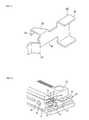
- Fig. 2 is a rear perspective view of a connector according to the invention, shown along with a slot 30.
- the slot 30 is provided with stopper release means 32 which are tapered at the tip, and has opened therein a guide device insertion port 33 for insertion of the guide device 24, and a contact receiving portion 34. Additionally, when plugging in the connector, the face 31 in which the guide device insertion port 33 and the contact receiving portion 34 are provided pushes the shutter 11 to release the detainment, to expose the first contact portion 25.
- the structure of the stopper 40 is shown in Fig. 3. As shown in the drawing, it consists of securing portions 44, 42 for securing the stopper to the housing, a shutter detaining portion 43 for detaining the shutter, a detaining portion support 45 and a stopper release portion 41.
- the stopper release portion 41 projects into the guide rails 22 positioned on both sides of the housing 20. While the details shall be described below, the shutter 11 is released from detainment when the stopper release means 32 presses against the stopper release portion 41 so as to move the shutter detaining portion 43.
- Fig. 4 is a partial cutaway view of the connector.
- a shutter 11 is provided inside the housing 20 so as to seal off the aperture portion 26 of the housing, and is pressed by a spring 23 installed in the guide device 24.
- the shutter 11 is detained against the housing by means of a claw 16 on a first detaining portion 13 (see Fig. 5).
- the center of the through hole 15 of the guide device of the shutter 11 is aligned with the center axis of the guide device 24 provided in the housing 20.
- a stopper 40 is provided adjacent to the shutter, and when unplugged, the shutter detaining portion 43 is positioned immediately behind a second shutter detaining portion 14 of the shutter 11.
- the stopper release portion 41 of the stopper 40 projects through an aperture portion 26 provided in the guide rail 22 to be positioned inside the guide rail 22.
- Fig. 5 is a drawing showing the state in which the shutter 11 is detained to the housing 20 by means of the claw 16 on the first detaining portion 13 of the shutter 11 in opposition to the pressure of the spring 23.
- the shutter 11 is detained and secured by means of the stopper 40, even when unplugged.
- a connector 10 and a slot 30 are brought opposite each other, and the connector 10 is inserted into the slot 30.
- stopper release means 32 in the slot 30 are inserted into the connector along guide rails 22.
- the stopper release means 32 contacts a stopper release portion 41 projecting into the guide rail. If the connector 10 is slid still further, the tapers of the stopper release means 32 press the stopper release portion toward the inside of the housing, while a securing portion 44 of the stopper is warped toward the inside of the housing.
- the shutter detaining portion 43 also moves from an initial position toward the inside of the housing. If the shutter detaining portion 43 is moved a sufficient distance, the detaining portion 43 is released from immediately behind the second detaining portion 14 of the shutter 11, thus releasing the shutter 11 from detainment.
- the face 31 of the slot 30 comes into contact with the shutter. Since the shutter 11 is already released from detainment at this time, the pressure from sliding the connector will cause the face 31 to slide the shutter 11. At this time, the second detaining portion 14 of the shutter 11 passes through the arch-shaped space formed by the shutter detaining portion 43 of the stopper 40, the detaining portion support 45 (see Fig. 3) and the stopper securing portion 44. As a result, the first connector portion of the connector is able to fit with a second contact portion in the slot.
- the stopper 40 is pressed by the stopper release means 32 of the slot and is thereby warped, so that the stopper release portion 41 contacts the stopper release means 32 and applies pressure to the stopper release means 32.
- the connector slides in this state. Additionally, at this time, the pressure of the spring 23 for pressing the shutter 11 causes the shutter 11 to be pressed outward with respect to the connector housing.
- the second detaining portion 14 of the shutter 11 arrives before the shutter detaining portion 43, i.e. on the housing aperture portion 26 side.
- the taper portion of the stopper release means reaches the position of the stopper release portion 41, whereupon the stopper release portion 41 moves along the slope of the taper due to the pressure from the warpage of the stopper securing portion 44, until the stopper release portion 41 finally projects into the guide rail 22 to return the stopper to its initial state.
- the shutter detaining portion 43 also moves similarly, and comes to a position immediately behind the second detaining portion 14 of the shutter 11. In this state, it becomes possible to detain the shutter 11.
- the shutter By further pulling the connector, the shutter can be pushed further outside the housing by the pressure from the spring 23, so that the first detaining portion 13 of the shutter 11 is detained by the housing 20 at a predetermined position (see Fig. 5), and the movement of the shutter 11 stops.
- the connector of the present invention primarily protects the contact portions of HDD's from contact with the hands as described above, those skilled in the art will recognize that it also has the effect of preventing invasion by dust. Additionally, the present invention is effective not only for HDD's, but also for other peripheral devices for computers, such as printers, DVD drives and the like, having a structure in which contact portions are exposed from the casing.
- Fig. 6 is a perspective view of the connector of the present invention, when connected with a so-called flat cable 60.
- One end of the flat cable is soldered to the back surface of the first contact portion of the connector, i.e. the end portion on the side which connects to the HDD.
- the other end of the flat cable is connected to the HDD, and the connector, cable and HDD are housed in a casing.
- the structure can be made to absorb impacts when dropped or the like, by housing them such that the HDD body is not rigidly affixed to the casing.
- the dotted chain line in Fig. 6 represents the casing for housing the connector, flat cable and HDD.
- FIGs. 7 and 8 Another embodiment of the present invention is shown in Figs. 7 and 8.
- a concave notch 70 is provided in the second detaining portion 14.
- a stopper release means 71 is provided along the slot. As shown in the drawing, the length of the stopper release means 71 is made shorter than the length of insertion of the connector.
- the stopper release means presses against the stopper release portion 41, thus releasing the detainment of the shutter, and causing the shutter to be pushed and slid away from the face 31 of the slot.
- the pressure applied to the stopper 40 by the stopper release means 71 is released at a predetermined position due to the fact that the stopper release means 71 is shorter than the connector insertion length.
- the shutter detaining portion 43 of the stopper fits into the notch 70 of the second detaining portion 14. As a result, the shutter is secured, and the first contact portion and second contact portion can be reliably fitted together.
- the second detaining portion 14 may be formed as a separate body of a material such as metal for attachment.
- the present invention offers a connector for peripheral devices such as HDD's with security chips or the like, the connector having a shutter to prevent the contact portions of the peripheral devices from being exposed to the outside when not plugged in as when being carried, especially damage to the electronic circuitry inside due to static electricity when touched by the hand, by providing a mechanism for detaining and securing the shutter when unplugged, thus protecting the contact portion.
Landscapes
- Connector Housings Or Holding Contact Members (AREA)
- Protection Of Pipes Against Damage, Friction, And Corrosion (AREA)
- Percussion Or Vibration Massage (AREA)
- Mechanical Coupling Of Light Guides (AREA)
Abstract
Description
In this case, not only does it become impossible to maintain the security of the data, but damage to the HDD control circuitry could make it impossible to read out the recorded data.
- 11
- shutter
- 12
- aperture portion for passage of first contact portion
- 13
- first detaining portion
- 14
- second detaining portion
- 15
- aperture for passage of guide device
- 16
- claw of first detaining portion
- 20
- housing
- 22
- guide rail
- 23
- spring for pressing shutter
- 24
- guide device
- 25
- first contact portion
- 26
- aperture portion for insertion of second contact portion
- 27
- aperture portion for projection of stopper
- 30
- slot
- 31
- face pressing against shutter
- 32
- stopper release means
- 33
- guide device insertion port
- 34
- contact receiving portion
- 40
- stopper
- 41
- stopper release portion
- 42
- stopper securing portion
- 43
- shutter detaining portion
- 44
- stopper securing portion
- 45
- detaining portion support
- 60
- flat cable
- 70
- notch
- 71
- stopper release means
Claims (8)
- A connector for a peripheral device with a shutter for protecting a first contact portion (25) comprising a housing (20) having an aperture (26) into which a second contact portion can be inserted characterized in that the connector comprises:a shutter (11) capable of closing the said aperture (26),a spring (23) for applying pressure to said shutter (11) in the closed position,a stopper (40) for detaining said shutter (11) in the closed position.
- Connector according to claim 1, wherein said housing (20) accommodates said shutter (11) spring (23) and stopper (40) characterized in that the shutter comprises a guiding device (15, 24) for guiding said shutter when said shutter slides in opposition to the pressure of said spring.
- Connector according to claims 1 and 2, characterized in that when the connector is not plugged in, the pressure of said spring (23) causes said shutter (11) to close the aperture in the vicinity of the housing end surface, and said shutter is detained and secured by said stopper(40).
- Connector according to claim 3, characterized in that the surface of said shutter is positioned to the rear of the surface of said housing.
- Connector according to claim 4, characterized in that the front surface of said shutter is positioned about 0.2 mm behind the front surface of the housing.
- Connector according to claims 1 and 2, characterized in that when the connector is plugged in, the stopper (40) operates as a securing means for securing the said shutter (11).
- Connector according to claims 1 and 2, characterized in that when the connector is inserted into a slot (30), stopper release means (32, 71) provided in the slot push said stopper to release the detainment of said shutter.
- Connector according to claim 7, characterized in that when plugging in the connector, said shutter (11) slides in opposition to the pressure of the spring (23) so that the first contact portion (25) of the peripheral device passes through an aperture (12) provided in said shutter to fit with a contact receiving portion of the slot (30).
Applications Claiming Priority (2)
| Application Number | Priority Date | Filing Date | Title |
|---|---|---|---|
| JP2001369701 | 2001-12-04 | ||
| JP2001369701A JP3814196B2 (en) | 2001-12-04 | 2001-12-04 | Connector with shutter |
Publications (3)
| Publication Number | Publication Date |
|---|---|
| EP1318568A2 true EP1318568A2 (en) | 2003-06-11 |
| EP1318568A3 EP1318568A3 (en) | 2003-10-22 |
| EP1318568B1 EP1318568B1 (en) | 2006-10-25 |
Family
ID=19179051
Family Applications (1)
| Application Number | Title | Priority Date | Filing Date |
|---|---|---|---|
| EP02026874A Expired - Lifetime EP1318568B1 (en) | 2001-12-04 | 2002-12-02 | Connector with shutter |
Country Status (7)
| Country | Link |
|---|---|
| US (1) | US6733311B2 (en) |
| EP (1) | EP1318568B1 (en) |
| JP (1) | JP3814196B2 (en) |
| AT (1) | ATE343859T1 (en) |
| DE (1) | DE60215604T2 (en) |
| SG (1) | SG103891A1 (en) |
| TW (1) | TWI276259B (en) |
Cited By (3)
| Publication number | Priority date | Publication date | Assignee | Title |
|---|---|---|---|---|
| WO2005025008A1 (en) * | 2003-09-09 | 2005-03-17 | Molex Incorporated | Electrical connector having protective shutter |
| EP2453274A1 (en) * | 2010-11-12 | 2012-05-16 | Research in Motion Limited | Device with magnetically coupled data connector for electrical and optical data circuits |
| CN103457082A (en) * | 2012-06-04 | 2013-12-18 | Smk株式会社 | Electric connector with shielding door |
Families Citing this family (19)
| Publication number | Priority date | Publication date | Assignee | Title |
|---|---|---|---|---|
| JP4133431B2 (en) * | 2003-02-25 | 2008-08-13 | 日本圧着端子製造株式会社 | Electrical connection plug |
| JP4181895B2 (en) * | 2003-02-25 | 2008-11-19 | 日本圧着端子製造株式会社 | Receptacle |
| JP2005025994A (en) * | 2003-06-30 | 2005-01-27 | Mitsumi Electric Co Ltd | Covered connector |
| TWM267694U (en) * | 2004-09-17 | 2005-06-11 | Hon Hai Prec Ind Co Ltd | Electrical connector |
| CN2766381Y (en) * | 2004-12-18 | 2006-03-22 | 富士康(昆山)电脑接插件有限公司 | Electronic card connector |
| DE202005002921U1 (en) * | 2005-02-23 | 2005-04-21 | Magcode Ag | Connection system, especially electrical connection system, with bayonet connection plug and socket has end of socket for connection to plug covered by cover adjustably arranged in socket so opening is exposed when plug inserted |
| JP4652890B2 (en) * | 2005-05-27 | 2011-03-16 | 日本圧着端子製造株式会社 | Receptacle |
| JP2008027861A (en) * | 2006-07-25 | 2008-02-07 | I-O Data Device Inc | Male connector, female connector, and connector structure |
| BRPI0700018A (en) * | 2007-01-09 | 2008-08-26 | 3M Innovative Properties Co | power distribution bus connector set and power distribution method using the same |
| US20090042433A1 (en) * | 2007-08-06 | 2009-02-12 | Bushby Donald P | Data connector plug with internal cover and locking system |
| US7766677B2 (en) * | 2008-09-16 | 2010-08-03 | Cheng Uei Precision Industry Co., Ltd. | Dustproof receptacle connector |
| US7883276B2 (en) * | 2008-10-14 | 2011-02-08 | Sonosite, Inc. | Optical transmission coupling |
| JP5401972B2 (en) * | 2008-12-18 | 2014-01-29 | ソニー株式会社 | Plugs, plug receptacles, and power supply systems |
| JP5366759B2 (en) * | 2009-10-28 | 2013-12-11 | 日本航空電子工業株式会社 | connector |
| JP5066619B2 (en) * | 2011-03-04 | 2012-11-07 | 日本航空電子工業株式会社 | Optical connector and optical connector device |
| CN103855519A (en) * | 2012-12-04 | 2014-06-11 | 富泰华工业(深圳)有限公司 | Socket with dust cover, and electronic device |
| JP6160767B2 (en) * | 2014-03-17 | 2017-07-12 | 株式会社リコー | Connector and electronic device including the connector |
| US9735494B2 (en) * | 2014-04-30 | 2017-08-15 | Te Connectivity Corporation | Pluggable connector having a protective front wall |
| US9419362B2 (en) * | 2014-08-06 | 2016-08-16 | Foxconn Interconnect Technology Limited | Electrical receptacle connector |
Family Cites Families (5)
| Publication number | Priority date | Publication date | Assignee | Title |
|---|---|---|---|---|
| JPH02222087A (en) * | 1989-02-23 | 1990-09-04 | Toshiba Corp | Recording medium connecting device |
| US5167516A (en) * | 1991-08-21 | 1992-12-01 | Foxconn International, Inc. | Connection with floating shield |
| JP2602786B2 (en) * | 1994-11-14 | 1997-04-23 | インターナショナル・ビジネス・マシーンズ・コーポレイション | Connectors and electronic devices using the connectors |
| JP3285321B2 (en) * | 1998-02-26 | 2002-05-27 | 日本圧着端子製造株式会社 | Adapter for card connection |
| US6109940A (en) * | 1998-10-09 | 2000-08-29 | Methode Electronics, Inc. | Shutter mechanism for card adapter |
-
2001
- 2001-12-04 JP JP2001369701A patent/JP3814196B2/en not_active Expired - Fee Related
-
2002
- 2002-11-20 SG SG200207007A patent/SG103891A1/en unknown
- 2002-11-26 TW TW091134307A patent/TWI276259B/en not_active IP Right Cessation
- 2002-12-02 DE DE60215604T patent/DE60215604T2/en not_active Expired - Fee Related
- 2002-12-02 AT AT02026874T patent/ATE343859T1/en not_active IP Right Cessation
- 2002-12-02 EP EP02026874A patent/EP1318568B1/en not_active Expired - Lifetime
- 2002-12-03 US US10/308,601 patent/US6733311B2/en not_active Expired - Lifetime
Cited By (3)
| Publication number | Priority date | Publication date | Assignee | Title |
|---|---|---|---|---|
| WO2005025008A1 (en) * | 2003-09-09 | 2005-03-17 | Molex Incorporated | Electrical connector having protective shutter |
| EP2453274A1 (en) * | 2010-11-12 | 2012-05-16 | Research in Motion Limited | Device with magnetically coupled data connector for electrical and optical data circuits |
| CN103457082A (en) * | 2012-06-04 | 2013-12-18 | Smk株式会社 | Electric connector with shielding door |
Also Published As
| Publication number | Publication date |
|---|---|
| ATE343859T1 (en) | 2006-11-15 |
| JP2003173841A (en) | 2003-06-20 |
| DE60215604T2 (en) | 2007-09-06 |
| EP1318568A3 (en) | 2003-10-22 |
| US6733311B2 (en) | 2004-05-11 |
| JP3814196B2 (en) | 2006-08-23 |
| SG103891A1 (en) | 2004-05-26 |
| DE60215604D1 (en) | 2006-12-07 |
| US20030119348A1 (en) | 2003-06-26 |
| EP1318568B1 (en) | 2006-10-25 |
| TW200409411A (en) | 2004-06-01 |
| TWI276259B (en) | 2007-03-11 |
Similar Documents
| Publication | Publication Date | Title |
|---|---|---|
| US6733311B2 (en) | Connector with shutter | |
| KR100424781B1 (en) | USB drive equipping bidirectional terminal USB plug | |
| JP4116484B2 (en) | Electronic component storage case and electronic device | |
| JP3173438B2 (en) | Memory card and mounting device | |
| US5035633A (en) | Data-processing apparatus in which a card-shaped recording medium is used | |
| US5679013A (en) | Electrical connector and an electronic apparatus using the electrical connector | |
| JP3683784B2 (en) | Card connector device | |
| KR100238909B1 (en) | IC card read / write device | |
| US6592041B1 (en) | Transfer apparatus and recording and/or reproduction method and transfer method and recording and/or reproduction method | |
| US6570759B1 (en) | Guide/ejector device for computer | |
| JP2004259051A (en) | Connector device for card | |
| JP4779096B2 (en) | Recording medium driving device | |
| KR20050090773A (en) | Door device for opening/closing memory card slot of camcorder | |
| JP3102580U (en) | Pin protector for memory card connector | |
| JP2001256466A (en) | Memory card mounting system | |
| JP3917834B2 (en) | Card connector device | |
| JP3674505B2 (en) | Recording medium mounting device | |
| JP2004311123A (en) | Connector device for card | |
| JP3546385B2 (en) | Card connector | |
| KR200304729Y1 (en) | USB storage device equipped with the cap for non-secession | |
| JP4264385B2 (en) | Recording medium mounting device | |
| JP4155885B2 (en) | Card connector device | |
| JP2005302129A (en) | Recording medium loading apparatus | |
| JP4779097B2 (en) | Recording medium driving device | |
| JP2007520838A (en) | Disc cartridge |
Legal Events
| Date | Code | Title | Description |
|---|---|---|---|
| PUAI | Public reference made under article 153(3) epc to a published international application that has entered the european phase |
Free format text: ORIGINAL CODE: 0009012 |
|
| AK | Designated contracting states |
Designated state(s): AT BE BG CH CY CZ DE DK EE ES FI FR GB GR IE IT LI LU MC NL PT SE SI SK TR |
|
| AX | Request for extension of the european patent |
Extension state: AL LT LV MK RO |
|
| PUAL | Search report despatched |
Free format text: ORIGINAL CODE: 0009013 |
|
| AK | Designated contracting states |
Kind code of ref document: A3 Designated state(s): AT BE BG CH CY CZ DE DK EE ES FI FR GB GR IE IT LI LU MC NL PT SE SI SK TR |
|
| AX | Request for extension of the european patent |
Extension state: AL LT LV MK RO |
|
| RIC1 | Information provided on ipc code assigned before grant |
Ipc: 7H 01R 13/648 B Ipc: 7H 01R 13/453 A |
|
| 17P | Request for examination filed |
Effective date: 20040421 |
|
| AKX | Designation fees paid |
Designated state(s): AT BE BG CH CY CZ DE DK EE ES FI FR GB GR IE IT LI LU MC NL PT SE SI SK TR |
|
| 17Q | First examination report despatched |
Effective date: 20040621 |
|
| GRAP | Despatch of communication of intention to grant a patent |
Free format text: ORIGINAL CODE: EPIDOSNIGR1 |
|
| GRAS | Grant fee paid |
Free format text: ORIGINAL CODE: EPIDOSNIGR3 |
|
| GRAA | (expected) grant |
Free format text: ORIGINAL CODE: 0009210 |
|
| AK | Designated contracting states |
Kind code of ref document: B1 Designated state(s): AT BE BG CH CY CZ DE DK EE ES FI FR GB GR IE IT LI LU MC NL PT SE SI SK TR |
|
| PG25 | Lapsed in a contracting state [announced via postgrant information from national office to epo] |
Ref country code: AT Free format text: LAPSE BECAUSE OF FAILURE TO SUBMIT A TRANSLATION OF THE DESCRIPTION OR TO PAY THE FEE WITHIN THE PRESCRIBED TIME-LIMIT Effective date: 20061025 Ref country code: SK Free format text: LAPSE BECAUSE OF FAILURE TO SUBMIT A TRANSLATION OF THE DESCRIPTION OR TO PAY THE FEE WITHIN THE PRESCRIBED TIME-LIMIT Effective date: 20061025 Ref country code: LI Free format text: LAPSE BECAUSE OF FAILURE TO SUBMIT A TRANSLATION OF THE DESCRIPTION OR TO PAY THE FEE WITHIN THE PRESCRIBED TIME-LIMIT Effective date: 20061025 Ref country code: IT Free format text: LAPSE BECAUSE OF FAILURE TO SUBMIT A TRANSLATION OF THE DESCRIPTION OR TO PAY THE FEE WITHIN THE PRE;WARNING: LAPSES OF ITALIAN PATENTS WITH EFFECTIVE DATE BEFORE 2007 MAY HAVE OCCURRED AT ANY TIME BEFORE 2007. THE CORRECT EFFECTIVE DATE MAY BE DIFFERENT FROM THE ONE RECORDED.SCRIBED TIME-LIMIT Effective date: 20061025 Ref country code: SI Free format text: LAPSE BECAUSE OF FAILURE TO SUBMIT A TRANSLATION OF THE DESCRIPTION OR TO PAY THE FEE WITHIN THE PRESCRIBED TIME-LIMIT Effective date: 20061025 Ref country code: BE Free format text: LAPSE BECAUSE OF FAILURE TO SUBMIT A TRANSLATION OF THE DESCRIPTION OR TO PAY THE FEE WITHIN THE PRESCRIBED TIME-LIMIT Effective date: 20061025 Ref country code: CH Free format text: LAPSE BECAUSE OF FAILURE TO SUBMIT A TRANSLATION OF THE DESCRIPTION OR TO PAY THE FEE WITHIN THE PRESCRIBED TIME-LIMIT Effective date: 20061025 Ref country code: FI Free format text: LAPSE BECAUSE OF FAILURE TO SUBMIT A TRANSLATION OF THE DESCRIPTION OR TO PAY THE FEE WITHIN THE PRESCRIBED TIME-LIMIT Effective date: 20061025 Ref country code: CZ Free format text: LAPSE BECAUSE OF FAILURE TO SUBMIT A TRANSLATION OF THE DESCRIPTION OR TO PAY THE FEE WITHIN THE PRESCRIBED TIME-LIMIT Effective date: 20061025 |
|
| RAP1 | Party data changed (applicant data changed or rights of an application transferred) |
Owner name: FCI |
|
| REG | Reference to a national code |
Ref country code: GB Ref legal event code: FG4D |
|
| REG | Reference to a national code |
Ref country code: CH Ref legal event code: EP |
|
| REG | Reference to a national code |
Ref country code: IE Ref legal event code: FG4D |
|
| PG25 | Lapsed in a contracting state [announced via postgrant information from national office to epo] |
Ref country code: IE Free format text: LAPSE BECAUSE OF NON-PAYMENT OF DUE FEES Effective date: 20061204 |
|
| REF | Corresponds to: |
Ref document number: 60215604 Country of ref document: DE Date of ref document: 20061207 Kind code of ref document: P |
|
| PG25 | Lapsed in a contracting state [announced via postgrant information from national office to epo] |
Ref country code: MC Free format text: LAPSE BECAUSE OF NON-PAYMENT OF DUE FEES Effective date: 20061231 |
|
| PG25 | Lapsed in a contracting state [announced via postgrant information from national office to epo] |
Ref country code: BG Free format text: LAPSE BECAUSE OF FAILURE TO SUBMIT A TRANSLATION OF THE DESCRIPTION OR TO PAY THE FEE WITHIN THE PRESCRIBED TIME-LIMIT Effective date: 20070125 Ref country code: DK Free format text: LAPSE BECAUSE OF FAILURE TO SUBMIT A TRANSLATION OF THE DESCRIPTION OR TO PAY THE FEE WITHIN THE PRESCRIBED TIME-LIMIT Effective date: 20070125 Ref country code: SE Free format text: LAPSE BECAUSE OF FAILURE TO SUBMIT A TRANSLATION OF THE DESCRIPTION OR TO PAY THE FEE WITHIN THE PRESCRIBED TIME-LIMIT Effective date: 20070125 |
|
| PG25 | Lapsed in a contracting state [announced via postgrant information from national office to epo] |
Ref country code: ES Free format text: LAPSE BECAUSE OF FAILURE TO SUBMIT A TRANSLATION OF THE DESCRIPTION OR TO PAY THE FEE WITHIN THE PRESCRIBED TIME-LIMIT Effective date: 20070205 |
|
| PG25 | Lapsed in a contracting state [announced via postgrant information from national office to epo] |
Ref country code: PT Free format text: LAPSE BECAUSE OF FAILURE TO SUBMIT A TRANSLATION OF THE DESCRIPTION OR TO PAY THE FEE WITHIN THE PRESCRIBED TIME-LIMIT Effective date: 20070326 |
|
| REG | Reference to a national code |
Ref country code: CH Ref legal event code: PL |
|
| ET | Fr: translation filed | ||
| PLBE | No opposition filed within time limit |
Free format text: ORIGINAL CODE: 0009261 |
|
| STAA | Information on the status of an ep patent application or granted ep patent |
Free format text: STATUS: NO OPPOSITION FILED WITHIN TIME LIMIT |
|
| 26N | No opposition filed |
Effective date: 20070726 |
|
| PGFP | Annual fee paid to national office [announced via postgrant information from national office to epo] |
Ref country code: NL Payment date: 20071109 Year of fee payment: 6 |
|
| PG25 | Lapsed in a contracting state [announced via postgrant information from national office to epo] |
Ref country code: GR Free format text: LAPSE BECAUSE OF FAILURE TO SUBMIT A TRANSLATION OF THE DESCRIPTION OR TO PAY THE FEE WITHIN THE PRESCRIBED TIME-LIMIT Effective date: 20070126 |
|
| PGFP | Annual fee paid to national office [announced via postgrant information from national office to epo] |
Ref country code: GB Payment date: 20071106 Year of fee payment: 6 |
|
| PG25 | Lapsed in a contracting state [announced via postgrant information from national office to epo] |
Ref country code: EE Free format text: LAPSE BECAUSE OF FAILURE TO SUBMIT A TRANSLATION OF THE DESCRIPTION OR TO PAY THE FEE WITHIN THE PRESCRIBED TIME-LIMIT Effective date: 20061025 |
|
| PG25 | Lapsed in a contracting state [announced via postgrant information from national office to epo] |
Ref country code: TR Free format text: LAPSE BECAUSE OF FAILURE TO SUBMIT A TRANSLATION OF THE DESCRIPTION OR TO PAY THE FEE WITHIN THE PRESCRIBED TIME-LIMIT Effective date: 20061025 Ref country code: LU Free format text: LAPSE BECAUSE OF NON-PAYMENT OF DUE FEES Effective date: 20061202 |
|
| PGFP | Annual fee paid to national office [announced via postgrant information from national office to epo] |
Ref country code: FR Payment date: 20071204 Year of fee payment: 6 |
|
| PG25 | Lapsed in a contracting state [announced via postgrant information from national office to epo] |
Ref country code: CY Free format text: LAPSE BECAUSE OF FAILURE TO SUBMIT A TRANSLATION OF THE DESCRIPTION OR TO PAY THE FEE WITHIN THE PRESCRIBED TIME-LIMIT Effective date: 20061025 |
|
| PGFP | Annual fee paid to national office [announced via postgrant information from national office to epo] |
Ref country code: DE Payment date: 20081230 Year of fee payment: 7 |
|
| GBPC | Gb: european patent ceased through non-payment of renewal fee |
Effective date: 20081202 |
|
| NLV4 | Nl: lapsed or anulled due to non-payment of the annual fee |
Effective date: 20090701 |
|
| REG | Reference to a national code |
Ref country code: FR Ref legal event code: ST Effective date: 20090831 |
|
| PG25 | Lapsed in a contracting state [announced via postgrant information from national office to epo] |
Ref country code: NL Free format text: LAPSE BECAUSE OF NON-PAYMENT OF DUE FEES Effective date: 20090701 Ref country code: GB Free format text: LAPSE BECAUSE OF NON-PAYMENT OF DUE FEES Effective date: 20081202 |
|
| PG25 | Lapsed in a contracting state [announced via postgrant information from national office to epo] |
Ref country code: FR Free format text: LAPSE BECAUSE OF NON-PAYMENT OF DUE FEES Effective date: 20081231 |
|
| PG25 | Lapsed in a contracting state [announced via postgrant information from national office to epo] |
Ref country code: DE Free format text: LAPSE BECAUSE OF NON-PAYMENT OF DUE FEES Effective date: 20100701 |