EP1318559A2 - Method for the production of membrane electrode assemblies for fuel cells - Google Patents
Method for the production of membrane electrode assemblies for fuel cells Download PDFInfo
- Publication number
- EP1318559A2 EP1318559A2 EP02026867A EP02026867A EP1318559A2 EP 1318559 A2 EP1318559 A2 EP 1318559A2 EP 02026867 A EP02026867 A EP 02026867A EP 02026867 A EP02026867 A EP 02026867A EP 1318559 A2 EP1318559 A2 EP 1318559A2
- Authority
- EP
- European Patent Office
- Prior art keywords
- layers
- membrane
- catalyst
- gas distribution
- cathode
- Prior art date
- Legal status (The legal status is an assumption and is not a legal conclusion. Google has not performed a legal analysis and makes no representation as to the accuracy of the status listed.)
- Granted
Links
Images

Classifications
-
- H—ELECTRICITY
- H01—ELECTRIC ELEMENTS
- H01M—PROCESSES OR MEANS, e.g. BATTERIES, FOR THE DIRECT CONVERSION OF CHEMICAL ENERGY INTO ELECTRICAL ENERGY
- H01M8/00—Fuel cells; Manufacture thereof
- H01M8/10—Fuel cells with solid electrolytes
- H01M8/1004—Fuel cells with solid electrolytes characterised by membrane-electrode assemblies [MEA]
-
- H—ELECTRICITY
- H01—ELECTRIC ELEMENTS
- H01M—PROCESSES OR MEANS, e.g. BATTERIES, FOR THE DIRECT CONVERSION OF CHEMICAL ENERGY INTO ELECTRICAL ENERGY
- H01M2300/00—Electrolytes
- H01M2300/0017—Non-aqueous electrolytes
- H01M2300/0065—Solid electrolytes
- H01M2300/0082—Organic polymers
-
- Y—GENERAL TAGGING OF NEW TECHNOLOGICAL DEVELOPMENTS; GENERAL TAGGING OF CROSS-SECTIONAL TECHNOLOGIES SPANNING OVER SEVERAL SECTIONS OF THE IPC; TECHNICAL SUBJECTS COVERED BY FORMER USPC CROSS-REFERENCE ART COLLECTIONS [XRACs] AND DIGESTS
- Y02—TECHNOLOGIES OR APPLICATIONS FOR MITIGATION OR ADAPTATION AGAINST CLIMATE CHANGE
- Y02E—REDUCTION OF GREENHOUSE GAS [GHG] EMISSIONS, RELATED TO ENERGY GENERATION, TRANSMISSION OR DISTRIBUTION
- Y02E60/00—Enabling technologies; Technologies with a potential or indirect contribution to GHG emissions mitigation
- Y02E60/30—Hydrogen technology
- Y02E60/50—Fuel cells
-
- Y—GENERAL TAGGING OF NEW TECHNOLOGICAL DEVELOPMENTS; GENERAL TAGGING OF CROSS-SECTIONAL TECHNOLOGIES SPANNING OVER SEVERAL SECTIONS OF THE IPC; TECHNICAL SUBJECTS COVERED BY FORMER USPC CROSS-REFERENCE ART COLLECTIONS [XRACs] AND DIGESTS
- Y02—TECHNOLOGIES OR APPLICATIONS FOR MITIGATION OR ADAPTATION AGAINST CLIMATE CHANGE
- Y02P—CLIMATE CHANGE MITIGATION TECHNOLOGIES IN THE PRODUCTION OR PROCESSING OF GOODS
- Y02P70/00—Climate change mitigation technologies in the production process for final industrial or consumer products
- Y02P70/50—Manufacturing or production processes characterised by the final manufactured product
Definitions
- MEA membrane electrode assemblies
- DMFC direct-methanol fuel cells
- Fuel cells transform a fuel and an oxidizing agent at locally separated electrodes into current, heat and water. Hydrogen or a gas being rich of hydrogen can be used as fuel and oxygen or air can be used as oxidizing agent.
- the process of energy transformation in fuel cells has an especially high efficiency. Due to this reason, fuel cells in combination with electric motors increasingly gain importance as an alternative to customary combustion engines.
- PEM fuel cells polymer electrolyte membrane fuel cells Due to its compact assembly, its power density as well as its high efficiency, polymer electrolyte membrane fuel cells (PEM fuel cells) are especially well suitable for the use as energy transformer in vehicles as well as in stationary applications.
- a PEM fuel cell can be operated with various fuels or combustion gases. Adequate are for example pure hydrogen or hydrogen containing reformate gases.
- Liquid methanol can be used in a direct methanol fuel cell. These fuels are transformed oxidatively at the anode by releasing cationic species, in most cases protons, and electrons. As oxidizing agent, pure oxygen or air is used at the cathode.
- the technology of fuel cells is described in detail in the technical literature (see, e.g., K. Kordesch und G. Simader, Fuel Cells and their applications, Verlag VCH, Weinheim, 1996).
- a membrane electrode assembly has a multi-layer structure.
- the central layer is formed by a polymer electrolyte layer capable of conducting ions.
- Each of both surfaces of the membrane being opposite to each other are in contact with one catalytic layer on which are disposed hydrophobic impregnated gas diffusion layers (so-called GDLs or "backings").
- GDLs hydrophobic impregnated gas diffusion layers
- the assembly consisting of catalytic layer and gas distribution substrate is called an electrode.
- One of the two electrodes forms the cathode and the other one is the anode of the membrane electrode assembly.
- the catalytic layers comprise a mixture of an ionomer with an electro-catalyst and eventually a bonding material like, e.g., PTFE.
- a bonding material like, e.g., PTFE.
- Precious metal blacks small particles of platinum or its alloys
- the polymer electrolyte membrane is formed of a proton-conducting polymer material and has a thickness of 20 ⁇ m to 200 ⁇ m.
- Those materials are also called "ionomer", in short.
- a tetrafluoroethylen-fluorovinylether copolymer with acid functions, especially sulphonic acid is used.
- acid functions especially sulphonic acid
- Such a material is distributed, e.g., by E.I. DuPont under the trademark Nafion®.
- fluorine-free ionomer materials such as sulphonated polyether ketones or sulphonated acryl ketones as well as doped polybenzimidazole can be used.
- Adequate ionomer materials are described by O. Savadogo in the "Journal of New Materials for Electrochemical Systems” I, 47-66 (1998).
- the gas diffusion layers are made of high-porous, electrically conducting carbon fiber substrates, such as, e.g., carbon fiber paper, carbon fiber fleece or a carbon fiber fabric with a thickness of 100 ⁇ m to 400 ⁇ m and a porosity of more than 50% up to 95%.
- the average pore diameter of the gas diffusion layer is in the range of 30 ⁇ m to 50 ⁇ m.
- the carbon fiber substrates are impregnated by a suspension of a hydrophobic polymer, preferably polytetrafluoroethylen (PTFE), and finally calcined at a temperature in the range of the melting point of the polymer.
- PTFE polytetrafluoroethylen
- a paste, in the following referred to as catalyst ink, from ion conducting polymers dispersed in a solvent and an electrocatalyst is prepared, applied with known application techniques to the carbon fiber substrate and then the solvent is evaporated at moderate temperatures.
- the ion conducting polymer in the catalyst ink is normally the same as the one of which the membrane is made.
- the porous structure of the electrode layers guarantees an optimal three-phase-contact between the ion conducting ionomer, the catalyst and the gaseous reactants. Thus, an easy exchange of protons between the polymer electrolyte membrane and the active centers of the catalyst is achieved.
- US 5,211,984 describes the coating of a polymer electrolyte membrane by a transfer method (decal method), wherein membranes in ion exchanged form (e.g., NA + -form) are used. Thin catalyst layers are produced having a layer thickness of less than 10 ⁇ m. The method comprises many processing steps, is cumbersome and cost intensive and thus only adequate for small series.
- EP 1 037 295 B1 describes a method for the application of electrode layers on a strip-shaped polymer electrolyte membrane; the method is used in the production of membrane electrode assemblies for PEM fuel cells.
- a predetermined pattern of the catalyst layers is continuously printed using an ink containing an electrocatalyst.
- the printed catalyst layers are dried immediately after printing at elevated temperatures.
- the required gas diffusion layers are applied to the free surfaces of the catalyst layers by adhering, laying or laminating. This method allows a continuous production of MEAs in industrial applications.
- DE 195 09 748 describes a method for the continuous production of a composite comprising an electrode material, a catalyst material and a polymer electrolyte membrane wherein a dry catalytic powder containing the electrode material, the catalyst material and the material of the solid electrolyte is used to form a catalyst layer on a carrier.
- This catalyst layer is heated on the side not facing the carrier for softening the solid electrolyte material and is rolled under pressure onto the polymer electrolyte membrane.
- Disadvantages of this method are dust production and high production costs. If there are coarse powder particles in the catalytic material, the membrane can additionally be perforated (development of pinholes) when the powder is rolled on.
- WO 97/50142 describes a continuous method for the coating of a polymer electrolyte membrane with catalytic components, wherein a strip-shaped polymer membrane is pulled through a bath of platinum salt solution. The adhering salt is then reduced to precious metal in a gas stream or a further bath. With this method, the polymer electrolyte membrane is coated on both surfaces. The solution of platinum salt can penetrate the membrane which leads to a deposition of precious metal in the interior of the membrane during the reduction. Additionally, the membrane can be damaged or polluted, due to the very acidic metal salt solution and the reduction bath.
- DE 195 48 421 describes a method for the production of a membrane electrode assembly wherein the bonding of the polymer electrolyte membrane with the catalyst layers and the das diffusion layers is achieved by a rolling process. This method is combersome, cost intensive and is not quite adequate for mass production.
- GDLs gas diffusion layers
- commercial electrodes of the company E-TEK which comprise a coating of a platinum supported catalyst on carbon black on a conventional gas diffusion layer.
- these electrodes are applied on both sides of a polymer electrolyte membrane.
- the electrical contact of the electrodes to the membrane can be improved by impregnating the catalyst layers with, e.g., a solution of an ionomer.
- the impregnated electrodes are dried before using them in the production of a fuel cell.
- the electrodes are pressed or laminated with a polymer electrolyte membrane to form a membrane electrode assembly.
- the membrane can be damaged or perforated by the gas diffusion layer (e.g., by sharp parts of the carbon fiber fleece or carbon fiber paper).
- the gas diffusion layer e.g., by sharp parts of the carbon fiber fleece or carbon fiber paper.
- Another disadvantage of the lamination process is that the porous gas diffusion layers, too, can be damaged or compressed irreversibly during the exertion of pressure. This can impair the electric properties and life of the completed membrane electrode assembly.
- the method according to the present invention solves the afore-mentioned problems of the known production methods by combining the method of direct coating with the lamination method for the production of membrane electrode assemblies.
- the catalyst layers of the anode and/or the cathode are each divided in at least two sub-layers, wherein the first sub-layers are applied directly to the membrane and the second sub-layers are applied to the corresponding gas diffusion layers.
- the two sub-layers of the anode are referred to as A1 and A2 and those of the cathode as K1 and K2, wherein digit 1 refers to the sub-layers applied directly to the membrane and digit 2 refers to the sub-layers applied to the gas distribution layer.
- a first catalyst layer (anode layer A1 and/or cathode layer K1) is applied directly to the polymer membrane in a single coating step.
- a second catalyst layer (cathode layer K2 and[/or] anode layer A2) is applied onto the corresponding gas distribution layers in a single coating step.
- the three resulting components (coated membrane and two coated gas diffusion layers) are then assembled to a membrane electrode assembly and incorporated in a PEM fuel cell.
- a lamination step at high pressures and high temperature is omitted and thus damaging of the membrane and/or the gas distribution layers is avoided.
- the typically used temperatures are at the level of the operation temperature of the PEM fuel cell (i.e., less than 100°C).
- the pressure exerted during fitting of the MEA into a PEM single cell or a PEM stack is less than 5 bar.
- the method according to the present invention enables the catalyst inks to be adapted to the substrates to be coated in order to achieve optimal coating results.
- catalyst inks are preferably used which contain mainly organic solvents, i.e., the catalyst inks contain more than 50 up to 90 wt.-% of organic solvents.
- catalyst inks which contain more than 50 up to 90 wt.-% water.
- penetration depth of the ink into the hydrophobic-made gas distribution layer is minimized as much as possible.
- known coating methods can be used which belong to the group of screen printing, offset printing, transfer printing, stencil printing, doctor blading or spraying. After the catalyst layers have been applied, they are dried at temperatures in the range of 50 to 150°C.
- the suggested method permits to give different hydrophobic characteristics to the sub-layers of anode and cathode.
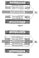
- Figure 1 shows the typical structure of a membrane electrode assembly according to the present invention comprising a polymer electrolyte membrane, the catalyst layers A1o and K1o applied to the membrane and the catalyst layers A2w and K2w applied to the hydrophobic gas distribution layers .
- the indices "o" and "w” of the catalyst layers indicate the catalyst inks containing mainly organic solvent (o) and mainly water (w), respectively.
- the intermediate layers between catalyst layers K1w or A1w and the gas distribution layers are optional.
- the intermediate layers are porous having an average pore diameter in the range of 0.1 ⁇ m and 1 ⁇ m. Therefore, they are often called micro layers. They are usually made of a mixture of carbon black and a hydrophobic polymer, as for example PTFE.
- Figure 2 shows the typical structure of a membrane electrode assembly according to the prior art which has been produced using water-containing catalyst inks. It has a polymer electrolyte membrane, the hydrophobic gas distribution layers and the catalyst layers A1w, A2w and K1w and K2w applied thereto.It was assumed that at least two coating steps A1w, A2w and K1w, K2w, respectively, were necessary for the application of the catalyst layers. The intermediate layers between the catalyst layers K1w or A1w and the gas distribution layers are optional.
- Figure 3 shows the typical structure of a membrane electrode assembly according to the prior art which has been produced using organic catalyst inks. It has a polymer electrolyte membrane and hydrophobic gas distribution layers.
- the catalyst layers A1o, A2o and K1o, K2o were directly applied to the polymer electrolyte membrane. It was assumed that also for the application of these catalyst layers at least two coating steps A1o, A2o and K1o, K2o, respectively, were necessary for each of them.
- the micro layers between the catalyst layers K2o and A2o, respectively, and the gas distribution layers are optional.
- the methods known from the prior art can be used. Suitable are the methods of painting, screen printing, offset printing, transfer printing, stencil printing, doctor blading or spraying.
- the catalyst materials used can be precious metals supported on carbon black, unsupported precious metal blacks (e.g., platinum black) or precious metals supported on oxide materials (e.g., Pt/Al 2 O 3 ).
- cathode catalyst preferably a platinum catalyst on carbon black is used.
- the preferred loading of carbon black with platinum is in the range of 20 to 75 wt.-% related to the total weight of platinum and carbon black.
- a catalyst is adequate which contains platinum and ruthenium in a mass relation of 2:1 on carbon black, whereby the concentration of the platinum group metals related to the total weight of the catalyst is again in the range of 20 to 70 wt.-%.
- Other catalyst materials are also usable.
- the polymer electrolyte membrane is usually hydrophilic while the gas distribution layers are in most cases hydrophobic.
- various surface characteristics develop which have to be taken into account when applying the catalyst layers.
- the present method facilitates now to adapt the application method for the catalyst material used optimally to the characteristics of the corresponding substrate.
- the catalyst ink should preferably be based on organic solvents (content of organic solvents 50 to 90 wt.-%).
- the adhering of the catalyst layer on the membrane is improved.
- the total water content of the ink should lie between 50 and 90 wt.-%.
- the catalysts are dispersed in a solution of an ionomer.
- an ionomer for the adjustment of the hydrophobicity of the catalyst layers additionally dispersion agents, pore builders, wetting agents, hydrophobic polymer as, e.g., PTFE or other additives can be added to the ink.
- the preferred weight relation between electro-catalyst and ionomer in the ink is between 5:1 and 1:5.
- catalyst inks which mainly contain water as solvent and are thus hydrophilic.
- the use of this hydrophilic catalyst inks reduces penetration into the pores of the hydrophobic gas distribution layers.
- organic solvents for example, linear dialcohols can be used, as described in DE 100 37 074 A1.
- the Nafion-solutions in dipropylene glycol were produced from an available Nafion-solution in low-boiling point alcohols (5% solution, Company DuPont), distilling off the alcohol and solving the Nafion in glycol. In this solution the catalyst was suspended. The ionomer is in acidic condition in this solution. Nafion-solutions in water (10% solution) are commercially available.
- the water-containing catalyst ink for the cathode (Kw) was applied to the first gas distribution layer (hydrophobic-made carbon fiber paper, Company Toray) by screen printing and dried in two steps at a temperature of 90°C.
- the loading of the cathode layer (K2w) produced in this manner was 0.2 mg Pt/cm 2 , its active cell area 50 cm 2 .
- a second gas distribution layer (hydrophobic-made carbon fiber paper, company Toray) was again coated by screen printing with a water-containing catalyst ink for the anode (Aw) and dried at 90°C.
- the anode layer (A2w) produced in this manner had a loading of 0,15 mg Pt/cm 2 and 0,075 mg Ru/cm 2 and had an active area of 50 cm 2 .
- the catalyst inks containing mainly organic solvents for the cathode (Ko) were directly applied to the ionomer membrane and dried at 70°C. Finally the membrane coated on one side was rinsed in hot water having a temperature of 80°C.
- the loading of the cathode catalyst layer (K1o) produced in this manner was 0.25 mg Pt/cm 2 and its active cell area was 50 cm 2 .
- the catalyst ink containing mainly organic solvents for the anode (Ao) was applied to the backward side of the ionomer membrane (anode catalyst layer A1o) and again dried at 70°C. Finally the membrane coated with catalyst on both sides was rinsed in hot water having a temperature of 80°C. The loading of the membrane coated in this manner was 0.15 mg Pt/cm 2 and 0.075 mg Ru/cm 2 on the anode side and 0.25 mg Pt/cm 2 on the cathode side, its active cell area was 50 cm 2 .
- the membrane coated on both sides was combined with the gas distribution layers, as shown in Figure 1, and incorporated into an PEM fuel cell.
- the total loading of the MEA produced in this manner was 0.9 mg precious metal/cm 2 (0.75 mg Pt/cm 2 and 0.15 mg Ru/cm 2 ).
- the cell voltages measured are shown in Table 1.
- a membrane electrode assembly was produced according to the method shown in Figure 2.
- the catalyst layer for anode and cathode were directly applied to the gas distribution layers using the catalyst inks Kw and Aw of example 1 and finally combined with a ionomer membrane (Nafion 112, company DuPont, thickness of the membrane: 50 ⁇ m).
- the cathode ink on aqueous basis was directly applied by screen printing to the first gas distribution layers (company Toray) and dried in two steps at 70°C and 90°C, respectively.
- the loading of this first catalyst layer (K1w) was 0.,2 mg/cm 2 .
- a second layer (K2w) was applied by screen printing and again dried in two steps at 70°C and 90°C, respectively.
- the coated gas distribution layer was rinsed in water having a temperature of 80°C.
- the total loading of the cathode electrode produced in this manner was 0.4 mg Pt/cm 2 , its active cell area was 50 cm 2 .
- a second gas distribution layer (company Toray) was also coated by screen printing with the aqueous anode ink (Aw) and dried in two steps at 70°C and 90°C, respectively.
- the loading of this first catalyst layer (A1w) was 0.2 mg/cm 2 .
- a second layer of catalyst ink (A2w) was applied by screen printing and again dried in two steps at 70°C and 90°C, respectively.
- the coated gas distribution layer was rinsed in hot water having a temperature of 80°C.
- the total loading of the anode electrode produced in this manner was 0.3 mg Pt/cm 2 and 0.15 Ru/cm 2 , its active cell area was 50 cm 2 .
- an uncoated ionomer membrane (Nafion 112, company DuPont, thickness of the membrane 50 ⁇ m), already swollen in water, was introduced between the cathode and the anode with the dried catalyst layers and pressed together for 10 minutes at a temperature of 150°C and at a pressure of 20 bar.
- the total loading of this MEA was 0.85 mg precious metall/cm 2 (0.7 mg Pt/cm 2 and 0.15 mg Ru/cm 2 ).
- the membrane electrode assembly produced in this manner was incorporated in a PEM fuel cell and measured. The measured cell voltages are shown in Table 1.
- a membrane electrode assembly was produced according to the method shown in Figure 3.
- the catalyst layers for cathode and anode using the catalyst inks Ko and Ao of example 1 were directly applied to the ionomer membrane (Nafion 112, company DuPont, thickness of the membrane: 50 ⁇ m).
- the cathode ink Ko was directly applied by screen printing on the ionomer membrane and dried in two steps at 70°C and 90°C, respectively.
- the loading of this first catalyst layer (K1o) was 0.2 mg/cm 2 .
- a second layer (K2o) was applied by screen printing and again dried in two steps at 70°C and 90°C, respectively.
- the total loading of the cathode produced in this manner was 0.4 mg Pt/cm 2 , its active cell area was 50 cm 2 .
- the still uncoated surface of the ionomer membrane was also coated directly by screen printing with the anode ink Ao and dried in two steps at 70°C and 90°C, respectively.
- the loading of this first catalyst layer (A1o) was 0.2 mg/cm 2 .
- a second layer (A2o) was applied by screen printing and dried in two steps at 70°C and 90°C, respectively.
- the total loading of the anode produced in this manner was 0.3 mg Pt/cm 2 and 0.15 mg Ru/cm 2 , its active cell area was 50 cm 2 .
- the membrane coated on both sides was rinsed in hot water having a temperature of 80°C.
- the membrane electrode assembly produced in this manner was incorporated together with the gas distribution layer (hydrophobic-made carbon fiber paper, company Toray) into a PEM fuel cell and measured.
- the total load of the MEA was 0.85 mg precious metal/cm 2 , comprising 0.7 mg Pt/cm 2 and 0.15 mg Ru/cm 2 .
- the measured cell voltages are shown in Table 1.
- the membrane electrode assemblies produced according to example 1 and comparison examples VB1 and VB2 were incorporated into a PEM fuel cell having an active cell area of 50 cm 2 .
- a gas mixture of 40 vol.-% H 2 , 35 vol.-% N 2 , 25 vol.-% CO 2 , 50 vppm CO with an additional air bleed of 3 vol.-% air was used.
- cathode gas air was used.
- the cell temperature was 70°C.
- the anode wetting was made at 85°C and the cathode wetting was made at 55°C.
- the pressure of the operation gases was 1 bar (absolute).
- the stoichiometry of the gases was 1.3 (anode gas) and 2.0 (cathode gas).
- the measured cell voltages in reformat operation at a current density of 600 mA/cm 2 are shown in Table 1. It is obvious that the membrane electrode assembly produced according to the present invention shows a considerably higher cell voltage and a higher power density.
- Results of the performance tests example cell voltage at 600 mA/cm 2 power density example 1 650 mV 390 mW/cm 2 VB 1 605 mV 363 mW/cm 2 VB 2 590 mV 354 mW/cm 2
- the membrane electrode assemblies produced according to example 1 and the comparison examples VB1 and VB2 were incorporated into a DMFC fuel cell with an active cell area of 50 cm 2 .
- a 2-molar methanol solution in water was used, the cell temperature was 60°C.
- cathode gas air at a pressure of 1 bar (absolute) was used.
- a power density (peak) of 100 mW/cm 2 was obtained.
- the membrane electrode assemblies according to the comparison examples had a performance density of about 50 mW/cm 2 .
Landscapes
- Life Sciences & Earth Sciences (AREA)
- Engineering & Computer Science (AREA)
- Manufacturing & Machinery (AREA)
- Sustainable Development (AREA)
- Sustainable Energy (AREA)
- Chemical & Material Sciences (AREA)
- Chemical Kinetics & Catalysis (AREA)
- Electrochemistry (AREA)
- General Chemical & Material Sciences (AREA)
- Fuel Cell (AREA)
- Inert Electrodes (AREA)
Abstract
Description
- Figure 1
- shows the schematic structure of a membrane electrode assembly according to the present invention. The catalyst layer is applied to the polymer membrane as well as to the gas distribution layers.
- Figure 2
- shows the schematic structure of a membrane electrode assembly according to the prior art. The catalyst layers are only applied to the gas distribution layers.
- Figure 3
- shows the schematic structure of a membrane electrode assembly according to the prior art. The catalyst layers are only applied to the ionomer membrane.
| Ko: ink for the cathode containing mainly organic solvents (coating of the ionomer membrane) | |
| 15.0 g | supported Pt catalyst (40 wt.-% Pt on carbon black, company OMG) |
| 36.0 g | Nafion® solution (10 wt.-% in dipropylene glycol) |
| 49.0 g | Dipropylene glycol |
| 100.0 g | |
| content of organic solvents: 81.4 wt.-% | |
| total water content: 0.0 wt.-% |
| Kw: ink for the cathode containing mainly water (coating of the gas distribution layer) | |
| 13.0 g | supported Pt catalyst (40 wt.-% Pt on carbon black, company OMG) |
| 41.0 g | Nafion® solution (10 wt.-% in water) |
| 30.0 g | water (salt-free) |
| 16.0 g | Dipropylene glycol |
| 100.0 g | |
| content of organic solvents: 0.0 wt.-% | |
| total water content: 66.9 wt.-% |
| Ao: ink for the anode containing mainly organic solvents (coating of the ionomer membrane) | |
| 11.0 g | supported PtRu catalyst (40 wt.-% Pt/Ru on carbon black: 26,4 wt.-% Pt, 13,6 wt.-% Ru; catalyst according to US 6,007,934) |
| 46.0 g | Nafion® solution (10 wt.-% in a solution of dipropylene glycol) |
| 43.0 g | Dipropylene glycol |
| 100.0 g | |
| content of organic solvents: 84.4 wt.-% | |
| total water content: 0.0 wt.-% |
| Aw: ink for the anode containing mainly water (coating of the gas distribution layer) | |
| 11.0 g | supported PtRu catalyst (40 wt.-% Pt/Ru on carbon black: 26,4 wt.-% Pt, 13,6 wt.-% Ru; catalyst according to US 6,007,934 |
| 35.0 g | Nafion® solution (10 wt.-% in water) |
| 30.0 g | water (salt-free) |
| 24.0 g | Dipropylene glycol |
| 100.0 g | |
| content of organic solvents: 24.0 wt.-% | |
| total water content: 66.9 wt.-% |
| Results of the performance tests | ||
| example | cell voltage at 600 mA/cm2 | power density |
| example 1 | 650 mV | 390 mW/cm2 |
| VB 1 | 605 mV | 363 mW/cm2 |
| VB 2 | 590 mV | 354 mW/cm2 |
Claims (9)
- A method for manufacturing a membrane electrode assembly comprising a polymer electrolyte membrane with two opposing membrane surfaces and a cathode electrode (cathode) and an anode electrode (anode) each comprising a catalyst layer and a gas distribution layer, wherein each catalyst layer is interposed between one membrane surface and the corresponding gas distribution layer and the catalyst layer of the cathode and/or catalyst layer of the anode comprises at least two sub-layers,
characterized in that
at least one of the sub-layers of the. cathode and/or the anode is applied directly to the membrane surface and the remaining sub-layers are applied to the corresponding gas distribution layers and only thereafter the assembly to the membrane electrode assembly is carried out. - The method according to claim 1,
characterized in that
for manufacturing of the sub-layers directly applied to the membrane surfaces catalyst inks containing mainly organic solvents and for manufacturing the sub-layers directly applied to the gas distribution layers catalyst inks containing mainly water are used. - The method according to any one of claims 1 or 2,
characterized in that
the assembly of the membrane electrode assembly is carried out by combining the membrane coated with catalyst layers with the two gas distribution layers coated with catalyst layers at pressures lower than 5 bar and at temperatures lower than 100°C. - The method according to claim 3,
characterized in that
the aqueous catalyst inks comprise a total water content of 50 up to 90 wt.-% and that the catalysts inks containing organic solvents comprise a content of organic solvents of 50 up to 90 wt.-%. - The method according to claim 4,
characterized in that
for manufacturing the sub-layers on the membrane and the gas distribution layers coating methods out of the group of screen printing, offset printing, transfer printing, stencil printing, doctor blading or spraying are used. - The method according to claim 5,
characterized in that,
for drying the electrode layers on the membrane and the gas distribution layers temperatures in the range of 50 to 150°C are used. - A membrane electrode assembly for membrane fuel cells,
characterized in that
the cathode and/or the anode comprise at least two sub-layers which comprise different hydrophobicities. - A membrane electrode assembly for membrane electrode fuel cells
manufactured according to the method according to any one of claims 1 to 6. - Use of the membrane electrode assembly produced according to the method according to any one of the claims 1 to 6 especially in polymer electrolyte fuel cells (PEM) and direct methanol fuel cells (DMFC).
Applications Claiming Priority (2)
| Application Number | Priority Date | Filing Date | Title |
|---|---|---|---|
| DE10159476A DE10159476A1 (en) | 2001-12-04 | 2001-12-04 | Process for the manufacture of membrane electrode assemblies for fuel cells |
| DE10159476 | 2001-12-04 |
Publications (4)
| Publication Number | Publication Date |
|---|---|
| EP1318559A2 true EP1318559A2 (en) | 2003-06-11 |
| EP1318559A3 EP1318559A3 (en) | 2006-02-08 |
| EP1318559B1 EP1318559B1 (en) | 2009-07-01 |
| EP1318559B9 EP1318559B9 (en) | 2009-12-16 |
Family
ID=7707959
Family Applications (1)
| Application Number | Title | Priority Date | Filing Date |
|---|---|---|---|
| EP02026867A Expired - Lifetime EP1318559B9 (en) | 2001-12-04 | 2002-12-02 | Method for the production of membrane electrode assemblies for fuel cells |
Country Status (4)
| Country | Link |
|---|---|
| US (1) | US7141270B2 (en) |
| EP (1) | EP1318559B9 (en) |
| JP (1) | JP4082999B2 (en) |
| DE (2) | DE10159476A1 (en) |
Cited By (7)
| Publication number | Priority date | Publication date | Assignee | Title |
|---|---|---|---|---|
| WO2005086271A1 (en) * | 2004-03-05 | 2005-09-15 | Umicore Ag & Co Kg | Membrane electrode unit |
| EP1601039A1 (en) * | 2004-05-25 | 2005-11-30 | Institute of Nuclear Energy Research | Method for manufacturing membrane electrode assembly of fuel cell by printing processes |
| FR2892861A1 (en) * | 2005-11-02 | 2007-05-04 | Commissariat Energie Atomique | Fabrication of a continuous catalyst-coated-backing electrode-membrane-electrode assembly for the subsequent fabrication of a proton exchange membrane fuel cell |
| WO2007089860A3 (en) * | 2006-01-31 | 2007-09-20 | Ballard Power Systems | Method of making membrane electrode assemblies |
| WO2007081443A3 (en) * | 2006-01-05 | 2007-10-11 | Matsushita Electric Industrial Co Ltd | Cathode electrodes for direct oxidation fuel cells and systems operating with concentrated liquid fuel at low oxidant stoichiometry |
| US7368200B2 (en) | 2005-12-30 | 2008-05-06 | Tekion, Inc. | Composite polymer electrolyte membranes and electrode assemblies for reducing fuel crossover in direct liquid feed fuel cells |
| EP1771902A4 (en) * | 2004-06-30 | 2009-09-16 | Georgia Tech Res Inst | MICROSTRUCTURES AND METHODS OF MAKING |
Families Citing this family (29)
| Publication number | Priority date | Publication date | Assignee | Title |
|---|---|---|---|---|
| US7098163B2 (en) * | 1998-08-27 | 2006-08-29 | Cabot Corporation | Method of producing membrane electrode assemblies for use in proton exchange membrane and direct methanol fuel cells |
| DE10145875B4 (en) * | 2001-09-18 | 2010-09-16 | Daimler Ag | Membrane electrode unit for a self-humidifying fuel cell |
| TW558833B (en) * | 2002-09-09 | 2003-10-21 | Ind Tech Res Inst | Gas diffusion electrode and the method for making the same |
| DE10325324A1 (en) * | 2003-06-04 | 2004-12-30 | Umicore Ag & Co.Kg | Membrane electrode unit for direct methanol fuel cells and process for their production |
| JP2005032528A (en) * | 2003-07-10 | 2005-02-03 | Equos Research Co Ltd | Fuel cell electrode |
| US7041191B2 (en) * | 2004-05-27 | 2006-05-09 | Institute Of Nuclear Energy Research | Method for manufacturing membrane electrode assembly of fuel cell by printing processes |
| KR100578969B1 (en) * | 2004-06-30 | 2006-05-12 | 삼성에스디아이 주식회사 | Electrode for fuel cell and fuel cell comprising same |
| US7816058B2 (en) | 2004-11-05 | 2010-10-19 | Gm Global Technology Operations, Inc. | Split architectures for MEA durability |
| US7923400B2 (en) * | 2004-12-14 | 2011-04-12 | Nissan Motor Co., Ltd. | Method of making an electrode for use in a battery |
| DE102004063457A1 (en) * | 2004-12-23 | 2006-07-06 | Volkswagen Ag | Membrane electrode unit for fuel cell, has catalyst containing layer arranged with polymer-intermixture between fuel cell membrane and gas diffusion layers in such a manner that water is stored and kept in electrode unit and/or membrane |
| US20060199068A1 (en) * | 2005-01-26 | 2006-09-07 | Lee Jong-Ki | Electrode and membrane/electrode assembly for fuel cells and fuel cell systems comprising same |
| US8168025B2 (en) * | 2006-04-21 | 2012-05-01 | Bdf Ip Holdings Ltd. | Methods of making components for electrochemical cells |
| US20070281198A1 (en) * | 2006-06-01 | 2007-12-06 | Lousenberg Robert D | Membranes electrode assemblies prepared from fluoropolymer dispersions |
| US20090214905A1 (en) * | 2007-01-08 | 2009-08-27 | California Institute Of Technology | Direct methanol fuel cell operable with neat methanol |
| CA2622183A1 (en) * | 2007-02-27 | 2008-08-27 | Sanyo Electric Co., Ltd. | Catalyst layer for fuel cells and fuel cell using the same |
| US7785752B2 (en) * | 2007-03-07 | 2010-08-31 | Panasonic Corporation | Fuel cell electrode and method for producing the same |
| JP5069927B2 (en) * | 2007-03-26 | 2012-11-07 | アイシン精機株式会社 | Membrane electrode assembly for fuel cell and method for producing the same |
| DE102007016905A1 (en) * | 2007-04-02 | 2008-10-09 | Staxera Gmbh | Interconnector arrangement and method for producing a contact arrangement for a fuel cell stack |
| JP5321003B2 (en) * | 2008-11-19 | 2013-10-23 | 凸版印刷株式会社 | Manufacturing method of membrane electrode assembly |
| WO2010132556A2 (en) * | 2009-05-12 | 2010-11-18 | University Of Maine System Board Of Trustees | Membrane and catalyst composite for membrane electrode assembly |
| US8735023B2 (en) * | 2009-12-14 | 2014-05-27 | GM Global Technology Operations LLC | Fuel cell with layered electrode |
| JP6001455B2 (en) * | 2009-12-22 | 2016-10-05 | スリーエム イノベイティブ プロパティズ カンパニー | Fuel cell electrode with nanostructured catalyst and dispersed catalyst sublayer |
| JP5696722B2 (en) * | 2010-03-19 | 2015-04-08 | 旭硝子株式会社 | Membrane electrode assembly for polymer electrolyte fuel cell and method for producing cathode for polymer electrolyte fuel cell |
| US9979026B2 (en) * | 2010-09-21 | 2018-05-22 | Los Alamos National Security, Llc | Non-precious metal catalysts prepared from precursors comprising cyanamide and polyaniline |
| FR2965214B1 (en) * | 2010-09-29 | 2013-08-30 | Commissariat Energie Atomique | INK REFRIGERATED JET DEVICE AND METHOD USING SUCH A DEVICE |
| FR2985523B1 (en) * | 2012-01-06 | 2014-11-28 | Commissariat Energie Atomique | POROUS ELECTRODE FOR PROTON EXCHANGE MEMBRANE |
| JP6098430B2 (en) * | 2013-04-15 | 2017-03-22 | 旭硝子株式会社 | Polymer electrolyte fuel cell |
| DE102014205033A1 (en) | 2014-03-18 | 2015-09-24 | Volkswagen Ag | Catalyst layer for a fuel cell and method for producing such |
| US11909083B2 (en) | 2018-12-28 | 2024-02-20 | Xerox Corporation | Apparatus and method for forming a multilayer extrusion comprising component layers of an electrochemical cell |
Family Cites Families (14)
| Publication number | Priority date | Publication date | Assignee | Title |
|---|---|---|---|---|
| US4876115A (en) * | 1987-01-30 | 1989-10-24 | United States Department Of Energy | Electrode assembly for use in a solid polymer electrolyte fuel cell |
| US5211984A (en) | 1991-02-19 | 1993-05-18 | The Regents Of The University Of California | Membrane catalyst layer for fuel cells |
| GB9504713D0 (en) * | 1995-03-09 | 1995-04-26 | Johnson Matthey Plc | Improved electrocatalytic material |
| DE19509748C2 (en) | 1995-03-17 | 1997-01-23 | Deutsche Forsch Luft Raumfahrt | Process for producing a composite of electrode material, catalyst material and a solid electrolyte membrane |
| GB9507012D0 (en) * | 1995-04-05 | 1995-05-31 | Johnson Matthey Plc | Improved electrode |
| DE19548421B4 (en) | 1995-12-22 | 2004-06-03 | Celanese Ventures Gmbh | Process for the continuous production of membrane electrode assemblies |
| DE59701326D1 (en) | 1996-06-26 | 2000-04-27 | Siemens Ag | METHOD FOR PRODUCING MEMBRANE ELECTRODE UNITS (ME) FOR POLYMER ELECTROLYTE MEMBRANE (PEM) FUEL CELLS |
| US5910378A (en) * | 1997-10-10 | 1999-06-08 | Minnesota Mining And Manufacturing Company | Membrane electrode assemblies |
| US6103077A (en) * | 1998-01-02 | 2000-08-15 | De Nora S.P.A. | Structures and methods of manufacture for gas diffusion electrodes and electrode components |
| CN1516311A (en) * | 1998-06-16 | 2004-07-28 | ���µ�����ҵ��ʽ���� | polymer electrolyte fuel cell |
| DE19910773A1 (en) * | 1999-03-11 | 2000-09-28 | Degussa | Process for applying electrode layers to a band-shaped polymer electrolyte membrane for fuel cells |
| JP4974403B2 (en) * | 2000-05-31 | 2012-07-11 | 日本ゴア株式会社 | Solid polymer electrolyte fuel cell |
| DE10037071A1 (en) * | 2000-07-29 | 2002-02-21 | Omg Ag & Co Kg | Precious metal nanoparticles, process for their production and use |
| DE10037074A1 (en) | 2000-07-29 | 2002-02-14 | Omg Ag & Co Kg | Ink for the production of membrane electrode assemblies for PEM fuel cells |
-
2001
- 2001-12-04 DE DE10159476A patent/DE10159476A1/en not_active Ceased
-
2002
- 2002-12-02 EP EP02026867A patent/EP1318559B9/en not_active Expired - Lifetime
- 2002-12-02 DE DE60232773T patent/DE60232773D1/en not_active Expired - Lifetime
- 2002-12-03 US US10/308,491 patent/US7141270B2/en not_active Expired - Fee Related
- 2002-12-04 JP JP2002353066A patent/JP4082999B2/en not_active Expired - Fee Related
Cited By (7)
| Publication number | Priority date | Publication date | Assignee | Title |
|---|---|---|---|---|
| WO2005086271A1 (en) * | 2004-03-05 | 2005-09-15 | Umicore Ag & Co Kg | Membrane electrode unit |
| EP1601039A1 (en) * | 2004-05-25 | 2005-11-30 | Institute of Nuclear Energy Research | Method for manufacturing membrane electrode assembly of fuel cell by printing processes |
| EP1771902A4 (en) * | 2004-06-30 | 2009-09-16 | Georgia Tech Res Inst | MICROSTRUCTURES AND METHODS OF MAKING |
| FR2892861A1 (en) * | 2005-11-02 | 2007-05-04 | Commissariat Energie Atomique | Fabrication of a continuous catalyst-coated-backing electrode-membrane-electrode assembly for the subsequent fabrication of a proton exchange membrane fuel cell |
| US7368200B2 (en) | 2005-12-30 | 2008-05-06 | Tekion, Inc. | Composite polymer electrolyte membranes and electrode assemblies for reducing fuel crossover in direct liquid feed fuel cells |
| WO2007081443A3 (en) * | 2006-01-05 | 2007-10-11 | Matsushita Electric Industrial Co Ltd | Cathode electrodes for direct oxidation fuel cells and systems operating with concentrated liquid fuel at low oxidant stoichiometry |
| WO2007089860A3 (en) * | 2006-01-31 | 2007-09-20 | Ballard Power Systems | Method of making membrane electrode assemblies |
Also Published As
| Publication number | Publication date |
|---|---|
| DE10159476A1 (en) | 2003-07-17 |
| DE60232773D1 (en) | 2009-08-13 |
| JP4082999B2 (en) | 2008-04-30 |
| US7141270B2 (en) | 2006-11-28 |
| JP2003187824A (en) | 2003-07-04 |
| EP1318559B1 (en) | 2009-07-01 |
| US20030118890A1 (en) | 2003-06-26 |
| EP1318559A3 (en) | 2006-02-08 |
| EP1318559B9 (en) | 2009-12-16 |
Similar Documents
| Publication | Publication Date | Title |
|---|---|---|
| EP1318559B1 (en) | Method for the production of membrane electrode assemblies for fuel cells | |
| US6844286B2 (en) | Water-based catalyst inks and their use for manufacture of catalyst-coated substrates | |
| US7419740B2 (en) | Membrane electrode unit for polymer electrolyte fuel cells and a process for the production thereof | |
| US6183898B1 (en) | Gas diffusion electrode for polymer electrolyte membrane fuel cells | |
| CA2238738C (en) | Gas diffusion electrode for polymer electrolyte membrane fuel cells | |
| US6523699B1 (en) | Sulfonic acid group-containing polyvinyl alcohol, solid polymer electrolyte, composite polymer membrane, method for producing the same and electrode | |
| US6893761B2 (en) | Process for producing a membrane electrode assembly and the membrane electrode assembly produced thereby | |
| US20220302486A1 (en) | Membrane electrode assembly | |
| US20040229108A1 (en) | Anode structure for direct methanol fuel cell | |
| US20110183232A1 (en) | Structures for gas diffusion electrodes | |
| US20030175575A1 (en) | PEM fuel cell stack and method of making same | |
| US20230307677A1 (en) | ELECTRODE STRUCTURES FOR MEMBRANE ELECTRODE ASSEMBLIES OPERATING GREATER THAN 8OºC | |
| EP1721355B1 (en) | Membrane electrode unit | |
| US8512912B2 (en) | Membrane-electrode unit for direct methanol fuel cells (DMFC) | |
| KR20140065283A (en) | Electrode for fuel cell, method for preparing the same, membrane electrode assembly for fuel cell the electrode and fuel cell including the membrane electrode assembly | |
| EP1365464B1 (en) | Continuous process for manufacture of gas diffusion layers for fuel cells | |
| EP1261058A2 (en) | A process for producing a membrane electrode assembly and the membrane electrode assembly produced thereby | |
| KR20090082457A (en) | Electrocatalyst layers for fuel cells and methods of making electrocatalyst layers for fuel cells | |
| US20100167160A1 (en) | Method For Producing Polymer Electrolyte Membrane For Solid Polymer Fuel Cell, Membrane Eelctrode Assembly For Solid Polymer Fuel Cell, and Solid Polymer Fuel Cell |
Legal Events
| Date | Code | Title | Description |
|---|---|---|---|
| PUAI | Public reference made under article 153(3) epc to a published international application that has entered the european phase |
Free format text: ORIGINAL CODE: 0009012 |
|
| 17P | Request for examination filed |
Effective date: 20021220 |
|
| AK | Designated contracting states |
Designated state(s): AT BE BG CH CY CZ DE DK EE ES FI FR GB GR IE IT LI LU MC NL PT SE SI SK TR |
|
| AX | Request for extension of the european patent |
Extension state: AL LT LV MK RO |
|
| RAP1 | Party data changed (applicant data changed or rights of an application transferred) |
Owner name: UMICORE AG & CO. KG |
|
| PUAL | Search report despatched |
Free format text: ORIGINAL CODE: 0009013 |
|
| AK | Designated contracting states |
Kind code of ref document: A3 Designated state(s): AT BE BG CH CY CZ DE DK EE ES FI FR GB GR IE IT LI LU MC NL PT SE SI SK TR |
|
| AX | Request for extension of the european patent |
Extension state: AL LT LV MK RO |
|
| AKX | Designation fees paid |
Designated state(s): DE FR GB IT NL |
|
| R17C | First examination report despatched (corrected) |
Effective date: 20060609 |
|
| RIC1 | Information provided on ipc code assigned before grant |
Ipc: H01M 8/10 20060101AFI20081208BHEP Ipc: H01M 4/86 20060101ALI20081208BHEP Ipc: H01M 4/88 20060101ALI20081208BHEP |
|
| GRAP | Despatch of communication of intention to grant a patent |
Free format text: ORIGINAL CODE: EPIDOSNIGR1 |
|
| GRAS | Grant fee paid |
Free format text: ORIGINAL CODE: EPIDOSNIGR3 |
|
| GRAA | (expected) grant |
Free format text: ORIGINAL CODE: 0009210 |
|
| AK | Designated contracting states |
Kind code of ref document: B1 Designated state(s): DE FR GB IT NL |
|
| REG | Reference to a national code |
Ref country code: GB Ref legal event code: FG4D |
|
| REF | Corresponds to: |
Ref document number: 60232773 Country of ref document: DE Date of ref document: 20090813 Kind code of ref document: P |
|
| PLBE | No opposition filed within time limit |
Free format text: ORIGINAL CODE: 0009261 |
|
| STAA | Information on the status of an ep patent application or granted ep patent |
Free format text: STATUS: NO OPPOSITION FILED WITHIN TIME LIMIT |
|
| 26N | No opposition filed |
Effective date: 20100406 |
|
| PGFP | Annual fee paid to national office [announced via postgrant information from national office to epo] |
Ref country code: DE Payment date: 20121128 Year of fee payment: 11 |
|
| PGFP | Annual fee paid to national office [announced via postgrant information from national office to epo] |
Ref country code: IT Payment date: 20121110 Year of fee payment: 11 Ref country code: GB Payment date: 20121128 Year of fee payment: 11 |
|
| PGFP | Annual fee paid to national office [announced via postgrant information from national office to epo] |
Ref country code: NL Payment date: 20121215 Year of fee payment: 11 Ref country code: FR Payment date: 20130107 Year of fee payment: 11 |
|
| REG | Reference to a national code |
Ref country code: DE Ref legal event code: R119 Ref document number: 60232773 Country of ref document: DE |
|
| REG | Reference to a national code |
Ref country code: NL Ref legal event code: V1 Effective date: 20140701 |
|
| GBPC | Gb: european patent ceased through non-payment of renewal fee |
Effective date: 20131202 |
|
| REG | Reference to a national code |
Ref country code: FR Ref legal event code: ST Effective date: 20140829 |
|
| REG | Reference to a national code |
Ref country code: DE Ref legal event code: R119 Ref document number: 60232773 Country of ref document: DE Effective date: 20140701 |
|
| PG25 | Lapsed in a contracting state [announced via postgrant information from national office to epo] |
Ref country code: DE Free format text: LAPSE BECAUSE OF NON-PAYMENT OF DUE FEES Effective date: 20140701 Ref country code: NL Free format text: LAPSE BECAUSE OF NON-PAYMENT OF DUE FEES Effective date: 20140701 |
|
| PG25 | Lapsed in a contracting state [announced via postgrant information from national office to epo] |
Ref country code: FR Free format text: LAPSE BECAUSE OF NON-PAYMENT OF DUE FEES Effective date: 20131231 Ref country code: GB Free format text: LAPSE BECAUSE OF NON-PAYMENT OF DUE FEES Effective date: 20131202 |
|
| PG25 | Lapsed in a contracting state [announced via postgrant information from national office to epo] |
Ref country code: IT Free format text: LAPSE BECAUSE OF NON-PAYMENT OF DUE FEES Effective date: 20131231 |
|
| PG25 | Lapsed in a contracting state [announced via postgrant information from national office to epo] |
Ref country code: IT Free format text: LAPSE BECAUSE OF NON-PAYMENT OF DUE FEES Effective date: 20131202 |