EP1318501A1 - Musical sound generator, portable terminal, musical sound generating method, and storage medium - Google Patents
Musical sound generator, portable terminal, musical sound generating method, and storage medium Download PDFInfo
- Publication number
- EP1318501A1 EP1318501A1 EP01956949A EP01956949A EP1318501A1 EP 1318501 A1 EP1318501 A1 EP 1318501A1 EP 01956949 A EP01956949 A EP 01956949A EP 01956949 A EP01956949 A EP 01956949A EP 1318501 A1 EP1318501 A1 EP 1318501A1
- Authority
- EP
- European Patent Office
- Prior art keywords
- data
- tone generator
- generator control
- hardware
- management information
- Prior art date
- Legal status (The legal status is an assumption and is not a legal conclusion. Google has not performed a legal analysis and makes no representation as to the accuracy of the status listed.)
- Withdrawn
Links
Images










Classifications
-
- G—PHYSICS
- G10—MUSICAL INSTRUMENTS; ACOUSTICS
- G10H—ELECTROPHONIC MUSICAL INSTRUMENTS; INSTRUMENTS IN WHICH THE TONES ARE GENERATED BY ELECTROMECHANICAL MEANS OR ELECTRONIC GENERATORS, OR IN WHICH THE TONES ARE SYNTHESISED FROM A DATA STORE
- G10H7/00—Instruments in which the tones are synthesised from a data store, e.g. computer organs
- G10H7/002—Instruments in which the tones are synthesised from a data store, e.g. computer organs using a common processing for different operations or calculations, and a set of microinstructions, e.g. programs, to control the sequence thereof
- G10H7/004—Instruments in which the tones are synthesised from a data store, e.g. computer organs using a common processing for different operations or calculations, and a set of microinstructions, e.g. programs, to control the sequence thereof with one or more auxiliary processor in addition to the main processing unit
-
- G—PHYSICS
- G10—MUSICAL INSTRUMENTS; ACOUSTICS
- G10H—ELECTROPHONIC MUSICAL INSTRUMENTS; INSTRUMENTS IN WHICH THE TONES ARE GENERATED BY ELECTROMECHANICAL MEANS OR ELECTRONIC GENERATORS, OR IN WHICH THE TONES ARE SYNTHESISED FROM A DATA STORE
- G10H1/00—Details of electrophonic musical instruments
-
- G—PHYSICS
- G10—MUSICAL INSTRUMENTS; ACOUSTICS
- G10H—ELECTROPHONIC MUSICAL INSTRUMENTS; INSTRUMENTS IN WHICH THE TONES ARE GENERATED BY ELECTROMECHANICAL MEANS OR ELECTRONIC GENERATORS, OR IN WHICH THE TONES ARE SYNTHESISED FROM A DATA STORE
- G10H1/00—Details of electrophonic musical instruments
- G10H1/0033—Recording/reproducing or transmission of music for electrophonic musical instruments
- G10H1/0041—Recording/reproducing or transmission of music for electrophonic musical instruments in coded form
- G10H1/0058—Transmission between separate instruments or between individual components of a musical system
-
- G—PHYSICS
- G10—MUSICAL INSTRUMENTS; ACOUSTICS
- G10H—ELECTROPHONIC MUSICAL INSTRUMENTS; INSTRUMENTS IN WHICH THE TONES ARE GENERATED BY ELECTROMECHANICAL MEANS OR ELECTRONIC GENERATORS, OR IN WHICH THE TONES ARE SYNTHESISED FROM A DATA STORE
- G10H2230/00—General physical, ergonomic or hardware implementation of electrophonic musical tools or instruments, e.g. shape or architecture
- G10H2230/005—Device type or category
- G10H2230/021—Mobile ringtone, i.e. generation, transmission, conversion or downloading of ringing tones or other sounds for mobile telephony; Special musical data formats or protocols therefor
-
- G—PHYSICS
- G10—MUSICAL INSTRUMENTS; ACOUSTICS
- G10H—ELECTROPHONIC MUSICAL INSTRUMENTS; INSTRUMENTS IN WHICH THE TONES ARE GENERATED BY ELECTROMECHANICAL MEANS OR ELECTRONIC GENERATORS, OR IN WHICH THE TONES ARE SYNTHESISED FROM A DATA STORE
- G10H2230/00—General physical, ergonomic or hardware implementation of electrophonic musical tools or instruments, e.g. shape or architecture
- G10H2230/025—Computing or signal processing architecture features
- G10H2230/041—Processor load management, i.e. adaptation or optimization of computational load or data throughput in computationally intensive musical processes to avoid overload artifacts, e.g. by deliberately suppressing less audible or less relevant tones or decreasing their complexity
-
- G—PHYSICS
- G10—MUSICAL INSTRUMENTS; ACOUSTICS
- G10H—ELECTROPHONIC MUSICAL INSTRUMENTS; INSTRUMENTS IN WHICH THE TONES ARE GENERATED BY ELECTROMECHANICAL MEANS OR ELECTRONIC GENERATORS, OR IN WHICH THE TONES ARE SYNTHESISED FROM A DATA STORE
- G10H2240/00—Data organisation or data communication aspects, specifically adapted for electrophonic musical tools or instruments
- G10H2240/011—Files or data streams containing coded musical information, e.g. for transmission
- G10H2240/046—File format, i.e. specific or non-standard musical file format used in or adapted for electrophonic musical instruments, e.g. in wavetables
- G10H2240/056—MIDI or other note-oriented file format
-
- G—PHYSICS
- G10—MUSICAL INSTRUMENTS; ACOUSTICS
- G10H—ELECTROPHONIC MUSICAL INSTRUMENTS; INSTRUMENTS IN WHICH THE TONES ARE GENERATED BY ELECTROMECHANICAL MEANS OR ELECTRONIC GENERATORS, OR IN WHICH THE TONES ARE SYNTHESISED FROM A DATA STORE
- G10H2240/00—Data organisation or data communication aspects, specifically adapted for electrophonic musical tools or instruments
- G10H2240/011—Files or data streams containing coded musical information, e.g. for transmission
- G10H2240/046—File format, i.e. specific or non-standard musical file format used in or adapted for electrophonic musical instruments, e.g. in wavetables
- G10H2240/061—MP3, i.e. MPEG-1 or MPEG-2 Audio Layer III, lossy audio compression
-
- G—PHYSICS
- G10—MUSICAL INSTRUMENTS; ACOUSTICS
- G10H—ELECTROPHONIC MUSICAL INSTRUMENTS; INSTRUMENTS IN WHICH THE TONES ARE GENERATED BY ELECTROMECHANICAL MEANS OR ELECTRONIC GENERATORS, OR IN WHICH THE TONES ARE SYNTHESISED FROM A DATA STORE
- G10H2240/00—Data organisation or data communication aspects, specifically adapted for electrophonic musical tools or instruments
- G10H2240/171—Transmission of musical instrument data, control or status information; Transmission, remote access or control of music data for electrophonic musical instruments
- G10H2240/201—Physical layer or hardware aspects of transmission to or from an electrophonic musical instrument, e.g. voltage levels, bit streams, code words or symbols over a physical link connecting network nodes or instruments
- G10H2240/241—Telephone transmission, i.e. using twisted pair telephone lines or any type of telephone network
- G10H2240/251—Mobile telephone transmission, i.e. transmitting, accessing or controlling music data wirelessly via a wireless or mobile telephone receiver, analogue or digital, e.g. DECT, GSM, UMTS
-
- G—PHYSICS
- G10—MUSICAL INSTRUMENTS; ACOUSTICS
- G10H—ELECTROPHONIC MUSICAL INSTRUMENTS; INSTRUMENTS IN WHICH THE TONES ARE GENERATED BY ELECTROMECHANICAL MEANS OR ELECTRONIC GENERATORS, OR IN WHICH THE TONES ARE SYNTHESISED FROM A DATA STORE
- G10H2240/00—Data organisation or data communication aspects, specifically adapted for electrophonic musical tools or instruments
- G10H2240/171—Transmission of musical instrument data, control or status information; Transmission, remote access or control of music data for electrophonic musical instruments
- G10H2240/281—Protocol or standard connector for transmission of analog or digital data to or from an electrophonic musical instrument
- G10H2240/311—MIDI transmission
-
- G—PHYSICS
- G10—MUSICAL INSTRUMENTS; ACOUSTICS
- G10H—ELECTROPHONIC MUSICAL INSTRUMENTS; INSTRUMENTS IN WHICH THE TONES ARE GENERATED BY ELECTROMECHANICAL MEANS OR ELECTRONIC GENERATORS, OR IN WHICH THE TONES ARE SYNTHESISED FROM A DATA STORE
- G10H2250/00—Aspects of algorithms or signal processing methods without intrinsic musical character, yet specifically adapted for or used in electrophonic musical processing
- G10H2250/541—Details of musical waveform synthesis, i.e. audio waveshape processing from individual wavetable samples, independently of their origin or of the sound they represent
- G10H2250/571—Waveform compression, adapted for music synthesisers, sound banks or wavetables
- G10H2250/581—Codebook-based waveform compression
- G10H2250/585—CELP [code excited linear prediction]
-
- G—PHYSICS
- G10—MUSICAL INSTRUMENTS; ACOUSTICS
- G10H—ELECTROPHONIC MUSICAL INSTRUMENTS; INSTRUMENTS IN WHICH THE TONES ARE GENERATED BY ELECTROMECHANICAL MEANS OR ELECTRONIC GENERATORS, OR IN WHICH THE TONES ARE SYNTHESISED FROM A DATA STORE
- G10H2250/00—Aspects of algorithms or signal processing methods without intrinsic musical character, yet specifically adapted for or used in electrophonic musical processing
- G10H2250/541—Details of musical waveform synthesis, i.e. audio waveshape processing from individual wavetable samples, independently of their origin or of the sound they represent
- G10H2250/571—Waveform compression, adapted for music synthesisers, sound banks or wavetables
- G10H2250/591—DPCM [delta pulse code modulation]
- G10H2250/595—ADPCM [adaptive differential pulse code modulation]
-
- H—ELECTRICITY
- H04—ELECTRIC COMMUNICATION TECHNIQUE
- H04M—TELEPHONIC COMMUNICATION
- H04M1/00—Substation equipment, e.g. for use by subscribers
- H04M1/72—Mobile telephones; Cordless telephones, i.e. devices for establishing wireless links to base stations without route selection
- H04M1/724—User interfaces specially adapted for cordless or mobile telephones
Definitions
- This invention relates to a musical tone-generating apparatus which has a simple construction and is capable of generating melodies, a mobile terminal apparatus, a musical tone-generating method, and a storage medium storing a program for executing the method.
- Conventional musical tone-generating apparatuses include a hardware musical tone-generating apparatus which uses hardware to generate musical tones, and a software musical tone-generating apparatus which causes a computer to execute a musical tone-generating program to generate musical tones.
- FIG. 25 shows an example of the arrangement of the conventional hardware musical tone-generating apparatus.
- a CPU Central Processing Unit 110 supplies music contents data 111, such as MIDI (Musical Instrument Digital Interface) data and SMAF (Synthetic Music Mobile Application Format) data, referred to hereinafter, to a hardware tone generator 115.
- the MIDI data and SMAF data may be transferred from the outside of the apparatus, or read from a storage means of the apparatus.
- the hardware tone generator 115 includes a sequencer 132, and a tone generator section implemented by hardware.
- the sequencer 132 has hardware-specific control data-generating section 132a which converts the MIDI data and the SMAF data to control data specific to the hardware tone generator 115, and a time management section 132b which manages the timing of sounding musical tones based on time management information contained in the data.
- the time management section 132b instructs the hardware-specific control data-generating section 132a to output data in timing based on interval data indicative of time intervals between events contained in the control data and gate time data indicative of a sounding time period. Responsive to the instruction, the hardware-specific control data-generating section 132a delivers the hardware-specific control data generated thereby to the tone generator section 133.
- the tone generator section 133 generates musical tones based on the supplied hardware-specific control data. Thus, the musical tones are reproduced.
- FIG. 26 shows an example of the arrangement of the conventional software musical tone-generating apparatus.
- a CPU 210 includes a sequencer function means 232 which is realized by a sequencer program executed by the CPU 210.
- the sequencer means 232 is comprised of a hardware-specific control data-generating means 210a, and a time management means 210b.
- the hardware-specific control data-generating means 210a which converts MIDI data and SMAF data 211 to control data specific to a hardware tone generator 215, while the time management means 210b controls the timing of sounding musical tones.
- the MIDI data and the SMAF data converted by the hardware-specific control data-generating means 210a may be transferred from the outside of the apparatus or read from a storage means of the apparatus.
- the hardware tone generator 215 which generates musical tones from the hardware-specific control data includes a tone generator section 233 implemented by hardware.
- the time management means 210b of the CPU 210 instructs the hardware-specific control data-generating means 210a to output data in timing based on duration data indicative of time intervals between events, arid gate time data indicative of a sounding time period, both of which data are contained in the converted hardware-specific control data.
- the hardware-specific control data-generating means 210a delivers the hardware-specific control data generated thereby to the hardware tone generator 215.
- the tone generator section 233 generates and outputs musical tones based on the hardware-specific control data supplied. The musical tones are thus reproduced by the software musical tone-generating apparatus.
- the sequencer 132 executes the conversion of the musical contents data and time management, which complicates the construction of the sequencer 132, resulting in an increased circuit size of the sequencer, and hence increased manufacturing costs.
- the CPU 210 carries out the conversion of musical contents data and time management, which imposes a large burden on the CPU 210, and hence a high-speed CPU is required. Particularly, when the CPU executes other processing with higher importance, such as communication control, as its main function, an expensive high-speed CPU is required to carry out the processing of the sequencer.
- the conventional hardware tone-generating apparatus and the conventional software tone-generating apparatus starts reproduction of a musical piece from the head thereof. This cause the inconvenience that when the musical piece is reproduced as an incoming call music for a cellular phone or the like, only the leading portion of the musical piece can be heard.
- a musical tone-generating apparatus comprising software process means for converting music contents data to hardware tone generator control data which can be reproducedand hardware tone generator means for generating a musical tone based on a parameter for generation of the musical tone which is contained in the hardware tone generator control data, whenever timing based on time management information contained in the hardware tone generator control data is reached.
- software process means converts music contents data to hardware tone generator control data, and time management is executed by hardware tone generator means. Therefore, the size of a circuit of a sequence provided in the hardware tone generator means can be reduced. In this case, the time management can be carried out by a simplified construction using counter means. Further, since the software process means is not required to carry out processing for the time management, a burden on the software process means can be reduced, thereby dispensing with the use of a high-speed CPU.
- the musical tone-generating apparatus includes storage means for storing the music contents "data, and the software process means converts the music contents data stored in the storage means to the hardware tone generator control data by making use of time during which the software process means has extra processing capability, and stores the converted hardware tone generator control data in the storage means.
- the software process means converts the music contents data stored in the storage means to the hardware tone generator control data by making use of time during which the software process means has extra processing capability. Therefore, it is possible to prevent a load from being concentrated on the software process means, whereby it is possible to further reduce the needs of a high-speed CPU.
- the hardware tone generator means includes buffer memory means that can store a predetermined amount of the hardware tone generator control data, and the software process means converts the music contents data in such an amount that the resulting hardware tone generator control data can be stored in the buffer memory means, and transfers the resulting hardware tone generator control data to the buffer memory means.
- the hardware tone generator means includes counter means for starting counting of clocks of a clock signal generated whenever a unit of reference time elapses, a tone generator control register that controls generation of the musical tone based on the parameter for generation of the musical tone, and write means for writing the parameter following the time management information into the tone generator control register when a count of the counter means becomes equal to or larger than a value indicated by the time management information.
- the musical tone-generating apparatus includes point register means for storing data of an arbitrary performance start point, and the hardware tone generator means generates musical tones based on hardware tone generator control data starting with a point corresponding to the data of the performance start point stored in the point register means.
- the musical tone-generating apparatus includes point register means for storing data of an arbitrary performance start point, and musical tones are reproduced based on hardware tone generator control data starting with a point corresponding to the data of the performance start point stored in the point register means. Therefore, it is possible to reproduce a musical piece as contents data starting with a desired point thereof. This makes it possible to listen to the musical piece reproduced as an incoming call music, starting with a desired point of the musical piece.
- the software process means converts the music contents data to the hardware tone generator control data
- time management information items have an identical value
- index information items indicative of addresses into which a parameter for generation of a musical tone is to be written are successive to each other
- an immediately following one of the index information items which immediately follows the time management information items is set to a leading index information item
- the parameter for generation of a musical tone which follows the immediately following index information item is formed by a plurality of parameters corresponding to the index information items successive to each other.
- time management information items have an identical value
- index information items indicative of addresses into which a parameter for generation of a musical tone is to be written are successive to each other
- an immediately following one of the index information items which immediately follows the time management information items is set to a leading index information item
- the parameter for generation of a musical tone which follows the immediately following index information item is formed by a plurality of parameters corresponding to the index information items successive to each other, whereby the amount of hardware-based tone generator control data cab be reduced, thereby reducing the burden on the software processing means and hardware-based tone generator means.
- the hardware tone generator means includes counter means for starting counting of clocks of a clock signal generated whenever a unit of reference time elapses, a tone generator control register that controls generation of the musical tone based on the parameter for generation of the musical tone, and write means for writing the parameter following the time management information into the tone generator control register when a count of the counter means becomes equal to or larger than a value indicated by the time management information, and if the parameter is formed by data of the plurality of parameters, writes each parameter data into the tone generator control register while incrementing the address indicated by the index information one by one.
- the software process means includes separator means for separating the hardware tone generator control data into the parameter for generating the musical tone and the time management information.
- the hardware tone generator control data is composed of units each comprising a set of the time management information, and at least one pair of an index designating an address of the tone generator control register and data of the parameter to be written into the address.
- each of the units of the tone generator hardware control data is formed by the time management information, the index, and the data of the parameter.
- the time management information includes a time management information-discriminating address which indicates whether or not data immediately following the time management information-discriminating address is data of the value indicated by the time management information.
- a mobile terminal apparatus comprising a musical tone-generating apparatus including software process means for converting music contents data to hardware tone generator control data which can be reproduced, the conversion processing device being realized by software, and hardware tone generator means for generating a musical tone based on a parameter for generation of the musical tone which is contained in the hardware tone generator control data, whenever timing based on time management information contained in the hardware tone generator control data is reached, and a processing device that performs processing of mobile terminal functions, wherein the software process means is realized by part of functions of the processing device.
- the musical tone-generating apparatus point register means for storing data of an arbitrary performance start point
- the hardware tone generator means generates musical tones based on hardware tone generator control data starting with a point corresponding to the data of the performance start point stored in the point register means.
- a musical tone-generating method comprising the steps of converting music contents data to hardware tone generator control data which can be reproduced, by software, and generating a musical tone based on a parameter for generation of the musical tone which is contained in the hardware tone generator control data, whenever timing based on time management information contained in the hardware tone generator control data is reached.
- a storage medium storing a program for causing a computer to execute a musical tone-generating method, the program comprising a conversion process module that converts music contents data to hardware tone generator control data which can be reproduced, and a hardware tone generator module that generates a musical tone based on a parameter for generation of the musical tone which is contained in the hardware tone generator control data, whenever timing based on time management information contained in the hardware tone generator control data is reached.
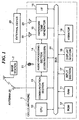
- FIG. 1 shows an example of the configuration of a cellular phone to which is applied a mobile terminal apparatus provided with a musical tone-generating apparatus according to a first embodiment of the present invention, together with a base station.
- the cellular phone 1 is provided with an antenna 25, which is generally a retractable type and can be connected to the base station 2 by radio.
- the antenna 25 is connected to a communication section 13 having a modulating/demodulating function.
- a CPU (Central Processing Unit) 10 serves as a system controller that controls components of the cellular phone 1 by executing a telephone function program, and includes a timer that indicates elapsed time during operation and generates a timer interrupt at predetermined time intervals. Further, the CPU 10 carries out processes related to generation of musical tones such as a data conversion process, as described in detail hereinafter.
- a RAM (Random Access Memory) 11 provides a storage area for storing music contents data of a distribution format which are downloaded from a download center or the like connected via the basic station 2, a storage area for storing hardware tone generator control data converted from the music contents data, and a work area for the CPU 10.
- a ROM (Read Only Memory) 12 stores various programs executed by the CPU 12 such as telephone function programs for sending or receiving a call, programs for processes related to generation of musical tones, and various data, such as preset hardware tone generator control data.
- the communication section 13 carries out demodulation of a signal received at the antenna 25, as well as modulation of a signal to be transmitted and supplies the modulated signal to the antenna 25.
- the incoming call signal demodulated by the communication section 13 is decoded by an audio processing section (coder/decoder) 14, and a call signal input from a microphone 21 is compression coded by the audio processing section 14.
- the audio processing section 14 subjects a sound or audio signal to high-efficiency compression encoding/decoding, and is implemented by a coder/decoder based on a CELP (Code Excited LPC) method and an ADPCM (Adaptive Differential PCM encoding) method.
- CELP Code Excited LPC
- ADPCM Adaptive Differential PCM encoding
- a hardware tone generator 15 converts the call signal received from the audio processing section 14 into sound to be sounded via a received message speaker 22, or generates an incoming call music or music-on-hold by reproducing the converted hardware tone generator control data. It should be noted that the incoming call music is sounded via an incoming call speaker 23, while the music-on-hold is sounded via the received message speaker 22 after being mixed with the incoming call signal.
- the format of music contents data there are employed a MID format and a SMAF format which are convenient to distribution of data, and the CPU 10 converts the music contents data in these formats into hardware tone generator control data having a format specific to the hardware tone generator 15, whereby it is possible to reproduce musical tones based on the data in these formats.
- the converted hardware tone generator control data can be stored in the RAM 11.
- the hardware tone generator 15 reproduces musical tones based on the hardware tone generator control data, and to this end, has provided therein a FIFO for temporarily storing a predetermined amount of the hardware tone generator control data.
- the FIFO may have a storage capacity large enough to store the whole of one musical piece, but if the capacity of the FIFO is not large enough to store the whole music piece, it may be so configured that whenever a predetermined amount of unused area is produced in the FIFO, the hardware tone generator 15 sends a FIFO data request signal to the CPU 10. Responsive to this request signal, the CPU 10 continues to read the following portion of the hardware tone generator data stored in the RAM 11 or ROM 12, and delivers the read data to the hardware tone generator 15. This makes it possible to reproduce a musical piece formed by a large amount of hardware tone generator control data even with a small-capacity FIFO.
- an interface (I/F) 16 provides interface for downloading music contents data and the like from an external apparatus 20, such as a personal computer.
- An input section 17 is an input means comprised of dial buttons for inputting "0" to "9", respectively, and other buttons.
- a display 18 displays a menu of options for selecting telephone functions, and images associated with operations of respective buttons, including the dial buttons.
- a vibrator 19 vibrates the body of the cellular phone 1 upon receipt of an incoming call in place of generating the incoming call sound. It should be noted that all the components and sections are connected to each other via a bus 24.
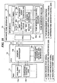
- FIG. 2 shows the construction of the musical tone-generating apparatus according to the first embodiment of the present invention, which is used in the cellular phone 1 as its hardware tone generator 15.
- the received message speaker 22, the incoming call speaker 23, and components associated therewith are omitted.
- the CPU 10, the hardware tone generator 15, and the RAM 11 are communicated with each other for transfer of data therebetween by the bus 24, though not shown in FIG. 2.
- the RAM 11 stores MID data, SMAF data and the like, formed as files, in an area 11a thereof. Further, when the CPU 10 has extra capability of processing or available processing time, the CPU 10 reads out musical contents data from the area 11a of the RAM 11 and carries out a converting process for converting the read data to hardware tone generator control data, to store the converted hardware tone generator control data in an area 11b of the RAM 11.
- the area 11a can store musical contents data of a plurality of musical pieces, and the area 11b can also store hardware tone generator control data of a plurality of musical pieces.
- the CPU 10 reads out musical contents data from the area 11a of the RAM 11 and carries out the converting process for converting the read data to hardware tone generator control data, which is stored in the area 11b of the RAM 11.
- the converting process is executed by a hardware tone generator control data-generating means 10b of the CPU 10, which is implemented by software.
- a memory controller 10a sequentially reads out music contents data to be converted from the area 11a of the RAM 11 starting from the leading portion of the data, and supplies the read data to a hardware tone generator control data-generating means 10b.
- the hardware tone generator control data-generating means 10b interprets the supplied music contents data and sequentially converts the same to hardware tone generator control data.
- the memory controller 10a sequentially writes the hardware tone generator control data thus obtained into the area 11b of the RAM 11. In this way, the CPU 10 converts the music contents data to the hardware tone generator control data.
- the memory controller 10a writes the hardware tone generator control data f thus obtained into a FIFO (First-In First-Out) 31 of the hardware tone generator 15.
- the hardware tone generator 15 includes the FIFO 31 capable of storing a predetermined amount of hardware tone generator control data, and a sequencer 32 sequentially reads out the hardware tone generator control data from the FIFO 31.
- the FIFO 31 is capable of storing e.g. 32 words of the hardware control data, in a First-In First-Out method, i.e. reads out the hardware tone generator control data in the order in which the data were written.
- the FIFO 31 sends a FIFO data request signal g to the memory controller 10a of the CPU 10, requesting the following hardware tone generator control data f to be transferred to the FIFO 31. This enables reproduction of a musical piece or pieces of a large amount of hardware tone generator control data by using a FIFO with a small capacity for the FIFO 31.
- the sequencer 32 of the hardware tone generator 15 includes a data decoder circuit 32b, which separates the hardware tone generator control data read out from the FIFO 31 into time management information and tone generator control register write data.
- a time management information-discriminating address is added to the hardware tone generator control data in a position immediately before the time management information, data, which is one byte, for example, following the time management information-discriminating address is separated as time management information.
- tone generator control register write data provides a parameter for generating musical tone, and is written into a tone generator control register 33a of a tone generator section 33 under the control of a register write controller 32c.
- the register write controller 32c writes the tone generator control register write data into the tone generator control register 33a in timing in which a register write-permitting signal d is outputted.
- the register write-permitting signal d is outputted in timing in which the count of a counter (timer) 32a becomes equal to a value of duration or a value of gate time contained in the time management information, as will be described hereinafter.
- the counter 32a of the sequencer 32 counts clock pulses output, e.g. at time intervals of 1 millisecond, as reference time units.
- the counting of the clock pulses is started when a sequencer start signal g output from the CPU 10 is applied to the counter 32a.
- the sequencer start signal g instructs starting of operation of the sequencer by writing data "01h” into a register 01h arranged within the sequencer 32 of the tone generator control register 33a, to thereby set "1" to a bit D0 (start) thereof. This causes the sequencer 32 to start sequencer processing, and when the counter 32a starts counting, the counter 32a applies a data decode start signal a to the data decoder circuit 32b.
- the data decoder circuit 32b is responsive to the data decode start signal a to read out hardware tone generator control data from the FIFO 31 and then extracts the time management information therefrom.
- the extracted time management information b is sent to the counter 32a, and when the count of the counter 32a becomes equal to or larger than the time management information b , the counter 32a applies the register write-permitting signal d to the register write controller 32c to write the tone generator control register write data c extracted by the data decoder circuit 32b into the tone generator control register 33a.
- This causes the tone generator section 33 to generate musical tones based on the tone generator control register write data c and output the musical tones.
- the data decoder circuit 32b reads out the next hardware tone generator control data from the FIFO 31.
- the data decoder circuit 32b extracts the next time management information from the read hardware tone generator control data, and the same process as described above is repeatedly carried out. That is, when the count of the counter 32a becomes equal to or larger than the next time management information b , the counter 32a applies the register write-permitting signal d to the register write controller 32c, to write the next tone generator control register write data c extracted by the data decoder circuit 32b into the tone generator control register 33a. This causes the tone generator section 33 to generate musical tones based on the next tone generator control register write data c and output the generated musical tones. Then, the data decoder circuit 32b reads out the second next hardware tone generator control data from the FIFO 31. Thus, the hardware tone generator control data is sequentially read from the FIFO 31, whereby the tone generator 33 reproduces musical tones.
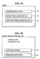
- the SMAF data has a chunk structure and is comprised of a contents information chunk (Contents Info Chunk) 40, a score track chunk 41, and a PCM audio track chunk 42.
- the contents information chunk 40 includes information and definitions of the contents
- the score track chunk 41 stores a tone generator sequence track
- the PCM audio track chunk 42 stores compressed PCM-type audio sounding data, such as ADPCM data, MP3 (MPEG audio layer 3) data, and TwinVQ data, in the form of events.
- the data structure of the score track chunk 41 is shown in FIG. 3B.
- the score track chunk 41 is comprised of data of a format type, a sequence type, etc., and chunks, such as a setup data chunk 43 and a sequence data chunk 44.
- the format type data indicates a status of the data in which the actual format of this chunk is defined, and can define the format type as a handy phone standard type, for instance.
- the sequence type data indicates one of two types of sequence data, i.e. a stream sequencer type and a sub-sequencer type.
- the setup data chunk 43 stores tone color data, settings of effects and the like, and the sequence data chunk 44 stores sequence data which is real performance data.
- the sequence data is comprised of pairs of data, each pair formed by one byte of duration data, and two or three bytes of event data, which are arranged in an alternating manner.
- the format is configured such that duration data necessarily exists before each event data.
- the duration data indicates time information indicative of a time interval between the event immediately preceding the duration data and an event immediately following the duration data.
- the events include a note message for controlling sounding, a control message for controlling a volume, a modulation, and the like, an exclusive message which can carry information peculiar to a maker of the data, etc.
- the note message is comprised of a channel number indicative of a designated sounding channel, a note number indicative of a tone pitch of a musical tone to be sounded, a gate time indicative of a duration of sounding.
- the FIG. 4 sequence data composed of duration data 1 to duration data 3 and event data 1 to event data 3 can be expressed along the time axis as shown in FIG. 5.
- an event 1, an event 2, and an event 3 are note messages for note on (sounding)
- the sounding by the event 1 is started upon the lapse of a time period indicated by the duration 1.
- the sounding by the event is stopped upon the lapse of a time period indicated by the gate time 1 after the start of sounding by the event 1, and then when a time period indicated by the duration 2 has elapsed after the lapse of the time period indicated by the duration 1, the sounding by the event 2 is started.
- the sounding by the event 2 is stopped. Further, when a time period indicated by the duration 3 has elapsed after the lapse of the time period indicated by the duration 2, the sounding by an event 3 is started. Then, when a time period indicated by the gate time 3 has elapsed after the start of sounding by the event 3, the sounding by the event 3 is stopped.
- the FIG. 4 sequence data is referred to as the "SMAF data".
- the hardware tone generator control data-generating means 10b converts music contents data, e.g. SMAF data, to hardware tone generator control data.
- the hardware tone generator control data formed by the conversion is sequentially transferred to the hardware tone generator 15, and the tone generator section 33 generates musical tones based on the hardware tone generator control data.
- the hardware tone generator control data is configured to have a data structure adapted to a register map of the tone generator control register 33a of the tone generator section 33.
- an example of hardware tone generator control data formed by converting the SMAF data is shown.
- the hardware tone generator control data contains time management information corresponding to duration and gate time, the time management information is not written into the tone generator control register 33a.
- Tone generator control register map-adapted data formed by eliminating the time management information from the hardware tone generator control data is shown in FIG. 6 in a manner associated with the SMAF data before conversion.
- duration data "00” and an event “00 30 47" of a program change message of SMAF data are converted to an index "18h” and data "10h".
- "h” indicates that the numerical value is in hexadecimal notation.
- the index designates the address of a register shown in the tone generator control register map of the tone generator control register 33a shown in FIG. 7, and the data following the index is written into a register having the address indicated by the index.
- each register has a capacity of one byte
- the tone generator control register 33a has one register to be addressed by an index "01h”, eight registers to be addressed by respective indexes "18h” to 1Fh", sixteen registers to be addressed by respective indexes "B0h” to “BFh”, sixteen registers to be addressed by respective indexes "C0h” to “CFh”, and sixteen registers to be addressed by respective indexes "E0h” to “EFh”.
- the register "01h” to be addressed by the index "01h” is arranged within the sequencer 32, as shown in FIG. 2.
- the length of each index is one byte, and hence each register is formed of eight bits, for storing data having the corresponding length of one byte.
- Each of the eight registers to be addressed by the respective indexes "18h” to “1Fh” is used for designating a tone color number of a channel n and a tone color number of a next channel n + 1. This enables designation of respective tone colors of sixteen channels. Further, each of the sixteen registers to be addressed by the respective indexes "B0h” to “BFh” stores less significant eight bits of an F number defined in ten bits representative of a numerical value proportional to the frequency of the tone pitch assigned to each key of a keyboard.
- each of the sixteen registers to be addressed by the respective indexes "C0h” to “CFh” stores the remaining more significant two bits of the F number at respective bits D0 and D1 thereof, three bits defining octave information at respective bits D2, D3, D4 thereof, and key-on information at a bit D5 thereof.
- each of the sixteen registers to be addressed by the respective indexes "E0h” to “EFh” stores five bits defining channel volume information at respective bits D0 to D4.
- the channel volume information can be designated for each of the sixteen channels.
- the data "10h” is stored in the register 18h, whereby the tone color having the tone color number "01h” is designated for the channel 1, and the tone color having the tone color number "1h” is designated for the channel 2.
- duration data "00” and an event “00 37 7F” of a channel volume message of the next SMAF data are converted to the index "E0h” and data "1Fh".
- the data “1Fh” formed by the conversion is stored in the register E0h, whereby the data "1Fh” designates the volume value of the channel 1 as "1Fh”.
- duration data "00" and an event “2C 50" of a note message of the next SMAF data are converted to the index “B0h” and data "B2h", and the index “C0h” and data “32h”.
- the data “B2h” formed by the conversion is stored in the register B0h
- the data "32h” formed by the conversion is stored in the register C0h.
- Ten bits formed by 0-th to 8-th bits provided by the data "B2h” (“1010010” in binary notation) and 9-th and 10-th bits at bits D0 and D1 of the data "32h” (“00110010” in binary notation) designates the F number of the channel 1.
- the three bits "100" at respective bits D2, D3, D4 of the data "32h” designate an octave of the channel 1. Further, “1" at a bit D5 of the data "32h” designates key-on of the channel 1.
- duration data "5C” and an event “2B 20" of a note message of the next SMAF data are converted to the index “B0h” and data “8Bh", and the index “C0h” and data “32h”.
- the data “8Bh” formed by the conversion is stored in the register B0h
- the data "32h” formed by the conversion is stored in the register C0h.
- Ten bits “1010001011” formed by 0-th to 8-th bits provided by the data "8Bh” ("10001011” in binary notation) and 9-th and 10-th bits at bits D0 and D1 of the data "32h” ("00110010” in binary notation) designate the F number of the channel 1.
- three bits “100” at bits D2, D3, D4 of the data "32h” designate an octave of the channel 1.
- "1" at a bit D5 of the data "32h” designates key-on of the channel 1.
- the SMAF data and tone generator control register map-adapted data formed by converting the SMAF data are associated with each other as described above, and the following data are also similarly converted.
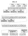
- Such note messages are not shown in FIG. 6, but are automatically generated by the hardware tone generator control data-generating means 10b during the data conversion, through interpretation of SMAF data before the conversion. Therefore, for the help of explanation, a first data structure of the hardware tone generator control data converted from the SMAF data which includes time management information is shown in FIG. 8, and an example of hardware tone generator control data having the first data structure formed by converting the FIG. 6 SMAF data is shown in FIG. 9. Further, the FIG. 9 hardware tone generator control data rearranged in sets of data is shown in FIG. 10.
- a time management information-discriminating address and time management information forms a set of data, and the time management information-discriminating address is arranged in a position immediately before the time management information. That is, when the time management information-discriminating address is detected, it is assumed that data following the detected time management information-discriminating address is time management information. Following the time management information, at least one set of data each formed by a pair of an index and data is provided.
- the index is information, as described hereinabove, which indicates an address of each register provided in the tone generator control register 33a, and the data following the index is written into the register indicated by the address.
- the hardware tone generator control data-generating means 10b converts the SMAF data to the hardware tone generator control data shown in FIG. 8.
- FIG. 9 shows the hardware tone generator control data formed by the hardware tone generator control data-generating means 10b interpreting and converting the FIG. 6 SMAF data.
- sequencer terminating data is also added in addition to the time management information. That is, the first data is set to "FFh” defined as the time management information-discriminating address, and then time management information "00h” as the duration data follows.
- the data following the duration data are, as described above, the set of data formed by the pair of the index "18h” and data "10h”, the set of data formed by the pair of the index "B0h” and data "B2h” and the pair of the index "C0h” and data "32h", and so forth.
- This sequence of data designates the tone colors of the channels 1 and 2, and the volume of the channel 1, as well as the key-on and a tone pitch of the channel 1.
- the following data is data, not shown in FIG. 6, for terminating the sounding of musical tones reproduced via the channel 1.
- the timing of start of the sounding of the channel 1 is set to timing indicated by the time management information "00h" arranged in a position immediately before the sounding data. Then, the sounding is terminated in timing of the lapse of the gate time.
- the time management information of data of which the sounding is to be stopped is a data value corresponding to the gate time.
- the data for terminating the sounding is formed by a set of data formed by a pair of "FFh” as the time management information-discriminating address and time management information "50h” and a set of data subsequent thereto formed by a pair of the index "B0h” and data "B2h” and a pair of the index "C0h” and data "12h”.
- This data causes the data "B2h” to be stored in the register B0h and the data “B2h” in the register C0h upon the lapse of the reference time "50h", whereby ten bits “1010110010” formed by 0-th to 8-th bits formed by the data "B2h” ("10110010” in binary notation") and 9-th and 10-th bits of "10” at bits D0 and D1 of the data "12h” ("00010010” in binary notation) designate the F number of the channel 1. Further, three bits “100” at bits D2, D3, D4, of the data "12h” designate the octave of the channel 1.
- the following data are also written in the tone generator control register 33a.
- the data "00h” is set to the register 01h of the tone generator control register 33a, which is arranged within the sequencer 32, in timing of the lapse of the reference time "01h” from the occurrence of the immediately preceding event. This sets “0” to the bit D0 (start) of the register 01h shown in FIG. 7, whereby the termination of sequencer operation is instructed to the sequencer 32.
- the index "01h” and data "00h” form the sequencer terminating data.
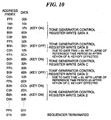
- FIG. 10 shows rearrangement of the hardware tone generator control data having the first data structure and formed by the hardware tone generator control data-generating means 10b through interpretation and conversion of the SMAF data, in sets of data.
- the hardware tone generator control data having the first data structure is composed of data each formed by a pair of a time management information-discriminating address and time management information and data each formed by a pair of an index and data.
- the operation of the FIG. 2 musical tone-generating apparatus performed when reproduction of a musical piece is instructed by designating the hardware tone generator control data thus converted from the SMAF data will be described with reference to FIGS. 2 and 10. It is assumed, however, that the hardware tone generator control data has been converted from the SMAF data by the CPU 10 and the resulting data has been stored in the area 11b of the RAM 11 prior to the reproduction of the musical piece.
- the memory controller 10a of the CPU 10 reads out hardware tone generator control data f shown in FIG. 10 which corresponds to the musical piece designated for reproduction from the area 11b of the RAM 1, e.g. by an amount of 32 bytes, and transfers the same to the FIFO 31 of the hardware tone generator 15. Simultaneously, the CPU 10 supplies the sequencer start signal g to the counter 32a of the sequencer 32.
- sequencer start signal g is written into the register 01h as part of the tone generator control register 33a to set "1" to the bit D0 (start) thereof, thereby instructing the sequencer operation to be started.
- This causes the sequencer 32 to start the sequencer operation, and the counter 32a operates in response to the sequencer start signal g to start counting clocks as units of the reference time, and at the same time applies the data decode start signal a to the data decoder circuit 32b.
- the data decoder circuit 32b operates in response to the data decode start signal a to read data from the FIFO 31 one byte by one byte. In this case, when the read data is the time management information-discriminating address "FFh", another byte is further read out. As shown in FIG. 10, data following the time management information-discriminating address is time management information, and therefore, this information is set to the counter 32a.
- the data decoder circuit 32b continues to read out the following data from the FIFO 31, and the index "18h” read out and the data "10h” read out in succession thereto are both tone generator control register write data, and hence sent to the register write controller 32c.
- the register write controller 32c prepares for writing the data "10h” into the register 18h having the address indicated by the index "18h".
- the time management information set to the counter 32a is "00h”, and hence the counter 32a instantly applies the register write-permitting signal d to the register write controller 32c, whereupon, responsive to this signal, the register write controller 32c writes the data "10h” into the register 18h of the tone generator control register 33a.
- the register 18h designates the tone cooler numbers of the channels 1 and 2, so that the tone colors of the channels 1 and 2 of musical tones generated from the tone generator section 33 are designated.
- the data decoder circuit 32b continues to read out the following data from the FIFO 31, and the index "E0h” read out and the data "1Fh” read out in succession thereto are both tone generator control register write data, and hence sent to the register write controller 32c.
- the register write controller 32c prepares for writing the data "1Fh” into the register E0h having the address indicated by the index "E0h”.
- the time management information set to the counter 32a is "00h”, and hence the counter 32a instantly applies the register write-permitting signal d to the register write controller 32c, whereupon, responsive to this signal, the register write controllers 32c writes the data "1Fh” into the register E0h of the tone generator control register 33a.
- the register E0h designates the channel volume of the channel 1, so that the channel volume of the channel 1 of a musical piece generated by the tone generator section 33 is designated.
- the data decoder circuit 32b continues to read out the following data from the FIFO 31, and the index "B0h” read out and the data "B2h” read out in succession thereto are both tone generator control register write data, and hence sent to the register write controller 32c.
- the register write controller 32c prepares for writing the data "B2h” into the register B0h having the address indicated by the index "B0h”.
- the time management information set to the counter 32a is "00h”, and hence the counter 32a instantly applies the register write-permitting signal d to the register write controller 32c, whereupon, responsive to this signal, the register write controller 32c writes the data "B2h” into the register B0h of the tone generator control register 33a.
- the register B0h designates the less significant eight bits of the F number of the channel 1.
- the data decoder circuit 32b continues to read out the following data read out from the FIFO 31, and the read index "C0h” and the data "32h” read out in succession thereto are both tone generator control register write data, and hence sent to the register write controller 32c.
- the register write controller 32c prepares for writing the data "32h” into the register C0h having the address indicated by the index "C0h”.
- the time management information set to the counter 32a is "00h”, and hence the counter 32a instantly applies the register write-permitting signal d to the register write controller 32c, whereupon, responsive to this signal, the register write controller 32c writes the data "32h” into the register C0h of the tone generator control register 33a.
- the data decoder circuit 32b reads out the following data from the FIFO 31, and the data read out is time management information-discriminating address "FFh”, and hence the time management information "50h” read out in succession thereto is set to the counter 32a as the time management information b .
- the data decoder circuit 32b reads out the following data from the FIFO 31, and the data read out is the index "B0h”, which is tone generator control register write data, and hence sent to the register write controller 32c together with the data "B2h” read out in succession thereto.
- the register write controller 32c prepares for writing the data "B2h” into the register B0h having the address indicated by the index "B0h".
- the time management information set to the counter 32a is "50h", and hence the process waits for the counter 32a to count up to a value corresponding to "50h”.
- the data decoder circuit 32b reads out the following data from the FIFO 31, and the data read out is the index "C0h", which is tone generator control register write data, and hence sent to the register write controller 32c together with the data "12h” read out in succession thereto.
- the register write controller 32c prepares for writing the data "12h” into the register C0h having the address indicated by the index "C0h”.
- the time management information set to the counter 32a is "50h", and hence the process waits for the counter 32a to count up to the value corresponding to "50h".
- the counting of the counter 32a progresses, and in timing a time period corresponding to "50h" has elapsed (time point 50h), the counter 32a applies the register write-permitting signal d to the register write controller 32c, whereupon, responsive to this signal, the register write controller 32c writes the data "B2h” into the register B0h of the tone generator control register 33a, and at the same time writes the data "12h” into the register C0h.
- the register B0h designates the less significant eight bits of the F number of the channel 1, while the register C0h designates an octave in cooperation with the more significant two bits of the F number of the channel 1, and at the same time designates the key-on/key-off of the channel 1, by the bit D5 thereof.
- the data decoder circuit 32b When the count of the counter 32a becomes equal to or larger than the value corresponding to "50h", the data decoder circuit 32b reads out the following data from the FIFO 31.
- the read data is time management information-discriminating address "FFh”, and hence the time management information "0Ch” read out in succession thereto is set to the counter 32a as the time management information b .
- the data decoder circuit 32b reads out the following data from the FIFO 31, and the data read out is the index "B0h”, which is tone generator control register write data, and hence sent to the register write controller 32c together with the data "8Bh” read out in succession thereto.
- the register write controller 32c prepares for writing the data "8Bh” into the register B0h having the address indicated by the index "B0h”.
- the time management information set to the counter 32a is "0Ch”, an hence the process waits for the counter 32a to count up to a value corresponding to "0Ch”.
- the data decoder circuit 32b reads out the following data from the FIFO 31, and the data read out is the index "C0h", which is tone generator control register write data, and hence sent to the register write controller 32c together with the data "32h” read out in succession thereto.
- the register write controller 32c prepares for writing the data "32h” into the register C0h having the address indicated by the index "C0h”.
- the time management information set to the counter 32a is "0Ch”, and hence the process waits for the counter 32a to count up to a value corresponding to "0Ch".
- the register B0h designates the less significant eight bits of the F number of the channel 1, while the register C0h designates an octave in cooperation with the more significant two bits of the F number of the channel 1, and at the same time designates the key-on/key-off of the channel 1.
- the data decoder circuit 32b continues to read out the following data from the FIFO 31.
- the read data is the time management information-discriminating address "FFh”, and hence the time management information "20h” read out in succession thereto is set to the counter 32a as the time management information b .
- the data decoder circuit 32b reads out the following data from the FIFO 31, and the data read out is the index "B0h", which is tone generator control register write data, and hence sent to the register write controller 32c together with the data "8Bh” read out in succession thereto.
- the register write controller 32c prepares for writing the data "8Bh" into the register B0h having the address indicated by the index "B0h".
- the time management information set to the counter 32a is "20h", and hence the process waits for the counter 32a to count "20h”.
- the data decoder circuit 32b reads out the following data from the FIFO 31, and the data read out is the index "C0h", which is tone generator control register write data, and hence sent to the register write controller 32c together with the data "12h” read out in succession thereto.
- the register write controller 32c prepares for writing the data "12h” into the register C0h having the address indicated by the index "C0h”.
- the time management information set to the counter 32a is "20h", and hence the process waits for the counter 32a to count up to the value corresponding to "20h".
- the counter 32a applies the register write-permitting signal d to the register write controller 32c, whereupon, responsive to this signal, the register write controller 32c writes the data "8Bh” into the register B0h of the tone generator control register 33a, and at the same time writes the data "12h” into the register C0h of the same.
- the register B0h designates the less significant eight bits of the F number of the channel 1, while the register C0h designates an octave in cooperation with the more significant two bits of the F number of the channel 1, and at the same time designates the key-on/key-off of the channel 1.
- the register write controller 32c prepares for writing the data "00h” ("00000000” in binary notation) to the register 01h having the address indicated by the index "01h”.
- the time management information set to the counter 32a is "01h”, and hence the process waits for the counter 32a to count up to the value corresponding to "01h”.
- the counting of the counter 32a progresses and in timing the time period corresponding to "01h” has elapsed, the counter 32a applies the register write-permitting signal d to the register write controller 32c, whereupon, responsive to this signal, the register write controller 32c writes the data "00h” into the register 01h arranged in the sequencer 32.
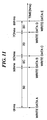
- FIG. 11 is a timing chart showing timing of writing data into the tone generator control register 33a.
- the abscissa designates time which is measured by 1 millisecond as units of the reference time. However, values of time are denoted in hexadecimal notation, and to indicate the method of denotation, time units are represented by hms.
- the counter 32a starts counting, the data associated with the time management information "00h" are written into the tone generator control register 33a. In this case, the written data are five pairs of tone generator control register write data A, i.e. the index "FFh" to the data "32h", shown in FIG. 10.
- the data following the time management information "50h”, which is the next time management information to "00h" are written into the tone generator control register 33a.
- the written data are two pairs of tone generator control register write data B, i.e. the index "B0h” to the data "12h", shown in FIG. 10.
- the written data are two pairs of tone generator control register write data C, i.e. the index "B0h” to the data "32h", shown in FIG. 10.
- the written data are two pairs pf tone generator control register write data D, i.e.
- the data following the time management information "0Dh”, which is the next time management information to "20h” are written into the tone generator control register 33a.
- the written data are four pairs of tone generator control register write data E, i.e. the index "B3h” to the data "32h", shown in FIG. 10.
- the following data are written into the tone generator control register 33a in the same manner as described above, until finally the sequencer terminating data formed by the index "01h” and the data "00h” are written into the register 01h arranged in the sequencer 32, as described hereinabove. In this case, the counting of the counter 32a is also stopped. If the reproduction of musical tones is instructed thereafter, the counter 32a is cleared, and then newly starts counting.
- tone generator control register 33a data following time management information are sequentially written into the tone generator control register 33a until the next time management information is read out. Further, parameters for generation of musical tones are written into the tone generator control register 33a in timing shown in FIG. 11, so that musical tones are generated in timing shown in FIG. 5.
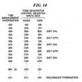
- FIG. 12 an example of a second data structure of the hardware tone generator control data formed by-conversion of the hardware tone generator control data-generating means 10b is shown in FIG. 12, and an example of the hardware tone generator control data having the second data structure corresponding to the FIG. 6 SMAF data is shown in FIG. 13. Further, the FIG. 13 hardware tone generator control data rearranged in sets of data is shown in FIG. 14.
- the hardware tone generator control data are each formed by a set of time management information, index, and data. That is, in this data structure, an index is provided immediately before data, and time management information is provided immediately before the index.
- the index is one-byte information as described above, which indicates the address of a corresponding one of the registers provided in the tone generator control register 33a, and the data, which is one byte, following the index is written into the register having the address. Further, timing in which the data is written into the register is indicated by one byte or two bytes of time management information. When the time management information is formed by two bytes, the MSB (most significant bit) of the first byte thereof is set to "1".
- the time management information is necessarily provided immediately before the index.
- the hardware tone generator control data having the second data structure are constituted by sets of data, each set having three bytes or four bytes, and time management information is arranged at the head of each set of data.
- FIG. 13 shows an example of the hardware tone generator control data having the second data structure which is formed by the hardware tone generator control data-generating means 10b through interpretation and conversion of the SMAF data.
- the hardware tone generator control data having the second data structure is composed of data each formed by a set of time management information, an index, and data.
- FIG. 14 shows the rearrangement of the FIG. 13 hardware tone generator control data having the second data structure according to the sets of data.
- the reproduction of a musical piece based on hardware tone generator control data having the second data structure will be described with reference to these figures and FIG. 2. It is assumed, however, that the SMAF data has been converted by the CPU 10 into the hardware tone generator control data and the resulting data has been stored in the area 11b of the RAM 11 prior to the reproduction of the musical piece.
- the memory controller 10a of the CPU 10 reads out hardware tone generator control data f shown in FIG. 14, which corresponds to the musical piece designated for reproduction and has the second data structure, from the area 11b of the RAM 1, e.g. by an amount of 32 bytes, and transfers the same to the FIFO 31 of the hardware tone generator 15. Simultaneously, the CPU supplies the sequencer start signal g to the counter 32a of the sequencer 32.
- sequencer start signal g is, written into the register 01h as part of the tone generator control register 33a to set "1" to the bit D0 (start) thereof, thereby instructing the start of sequencer operation.
- This causes the sequencer 32 to start the sequencer operation, and responsive to the sequencer start signal g , the counter 32a starts counting of clocks as units of the reference time, and at the same time applies the data decode start signal a to the data decoder circuit 32b.
- the data decoder circuit 32b reads data from the FIFO 31 one byte by one byte.
- the first data read out is time management information
- this data "00h” is set to the counter 32a as time management information b .
- the MSB of the time management information is "0", and hence this set of data amounts to a total of three bytes.
- the index "18h” read out and the data "10h” read out in succession thereto are both tone generator control register write data, and hence sent to the register write controller 32c.
- the register write controller 32c prepares for writing the data "10h” into the register 18h having the address indicated by the index "18h”.
- the time management information set to the counter 32a is "00h”
- the counter 32a instantly applies the register write-permitting signal d to the register write controller 32c, whereupon, responsive to this signal, the register write controller 32c writes the data "10h” into the register 18h having the address indicated by the index "18h”.
- the register 18h designates the tone cooler numbers of the channels 1 and 2, so that the tone colors of the channels 1 and 2 of musical tones generated from the tone generator section 33 are designated.
- the data decoder circuit 32b continues to read the following set of data from the FIFO 31, and the first data of the set read out is time management information "00h", which is set to the counter 32a as the time management information b .
- the MSB of the time management information is "0”, and hence this set of data also amounts to a total of three bytes.
- the index "E0h” read out and the data "1Fh” read out in succession thereto are both tone generator control register write data, and hence sent to the register write controller 32c.
- the register write controller 32c prepares for writing the data "1Fh" into the register E0h having the address indicated by the index "E0h".
- the time management information set to the counter 32a is "00h”, and hence the counter 32a instantly applies the register write-permitting signal d to the register write controller 32c, whereupon, responsive to this signal, the register write controller 32c writes the data "1Fh" into the register E0h of the tone generator control register 33a.
- the register E0h designates the channel volume of the channel 1, so that the channel volume of the channel 1 of a musical piece generated by the tone generator section 33 is designated.
- the data decoder circuit 32b continues to read the following set of data from the FIFO 31, and the first data of the set read out is time management information "00h", which is set to the counter 32a as the time management information b .
- the MSB of the time management information is "0”, and hence this set of data also amounts to a total of three bytes.
- the index "B0h” read out and the data "B2h” read out in succession thereto are both tone generator control register write data, and hence sent to the register write controller 32c.
- the register write controller 32c prepares for writing the data "B2h” into the register B0h having the address indicated by the index "B0h In this case as well, the time management information set to the counter 32a is "00h", and hence the counter 32a instantly applies the register write-permitting signal d to the register write controller 32c, whereupon, responsive to this signal, the register write controller 32c writes the data "B2h” into the register B0h of the tone generator control register 33a.
- the register B0h designates the less significant eight bits of the F number of the channel 1.
- the data decoder circuit 32b continues to read the following set of data from the FIFO 31, and the first data of the set read out is time management information "00h", which is set to the counter 32a as the time management information b .
- the MSB of the time management information is "0”, and hence this set of data also amounts to a total of three bytes.
- the index "C0h” read out and the data "32h” read out in succession thereto are both tone generator control register write data, and hence sent to the register write controller 32c.
- the register write controller 32c prepares for writing the data "32h” into the register C0h having the address indicated by the index "C0h".
- the time management information set to the counter 32a is "00h”, and hence the counter 32a instantly applies the register write-permitting signal d to the register write controller 32c, whereupon, responsive to this signal, the register write controller 32c writes the data "32h” into the register C0h of the tone generator control register 33a.
- the data decoder circuit 32b continues to read the following set of data from the FIFO 31, and the first data of the set read out is time management information "50h", which is set to the counter 32a as the time management information b .
- the MSB of the time management information is "0”, and hence this set of data also amounts to a total of three bytes.
- the data decoder circuit 32b reads out the following data from the FIFO 31.
- the data read out is the index "B0h”, which is tone generator control register write data, and hence sent to the register write controller 32c together with the data "B2h” read out in succession thereto.
- the register write controller 32c prepares for writing the data "B2h” into the register B0h having the address indicated by the index "B0h”.
- the time management information set to the counter 32a is "50h”, and hence the process waits for the counter 32a to count a value corresponding to "50h”.
- the counting of the counter 32a progresses, and in timing a time period corresponding to "50h" has elapsed (time point 50h), the counter 32a applies the register write-permitting signal d to the register write controller 32c, whereupon, responsive to this signal, the register write controller 32c writes the data "B2h” into the register B0h of the tone generator control register 33a.
- the register B0h designates the less significant eight bits of the F number of the channel 1.
- the data decoder circuit 32b continues to read out the following set of data from the FIFO 31, and the first data of the set read out is time management information "00h", which is set to the counter 32a as the time management information b .
- the MSB of the time management information is "0”, and hence this set of data also amounts to a total of three bytes.
- the data read out is the index "C0h”, which is tone generator control register write data, and hence sent to the register write controller 32c together with the data "12h” read out in succession thereto.
- the register write controller 32c prepares for writing the data "12h” into the register C0h having the address indicated by the index "C0h".
- the time management information set to the counter 32a is "00h", and hence the counter 32a instantly applies the register write-permitting signal d to the register write controller 32c.
- the register write controller 32c operates in response to this signal to write the data "12h” into the register the register C0h of the tone generator control register 33a.
- the register C0h designates an octave in cooperation with the more significant two bits of the F number of the channel 1, and at the same time designates the key-on/key-off of the channel 1.
- time management information "50h" which designates the key-off corresponds to the gate time of the SMAF data.
- the data is written into the tone generator control register 33a.
- the first data of a set of data read out by the data decoder circuit 32b from the FIFO 31 is time management information "80h".
- the MSB of the time management information is "1”, which means that the time management information of this set of data is expressed by two bytes. Therefore, the following time management information "32h” is read out in succession and the data read out "80h” and "32h” are set to the counter 32a as the time management information b . In this case, this set of data amounts to a total of four bytes.
- the data decoder circuit 32b reads out the following data from the FIFO 31, and the data read out is the index "C0h", which is tone generator control register write data, and hence sent to the tone generator control register 32a together with the data "32h” read in succession thereto.
- the register write controller 32c prepares for writing the data "32h” into the register C0h having the address indicated by the index "C0h”.
- the time management information set to the counter 32a is "80h 32h", and hence the process waits for the counter 32a to count up to a value corresponding to (80h 32h).
- the counting of the counter 32a progresses, and in timing a time period corresponding to "80h 32h" has elapsed, the counter 32a applies the register write-permitting signal d to the register write controller 32c, whereupon, responsive to this signal, the register write controller 32c writes the data "32h” into the register C0h of the tone generator control register 33a.
- time management information "01h”, the index "01h” and the data "00h”, are read out from the FIFO 31.
- the time management information "01h” is set to the counter 32a as the time management information b , and the index "01h” read out in succession thereto is sent to the register write controller 32c as the tone generator control register write data c .
- the data decoder circuit 32b sends the data "00h” read out in succession thereto to the register write controller 32c.
- the register write controller 32c prepares for writing the data "00h” ("00000000" in binary notation) into the register 01h having the address indicated by the index "01h”.
- the time management information set to the counter 32a is "01h” and hence the process waits for the counter 32a to count up to a value corresponding to "01h”.
- the counting of the counter 32a progresses and in timing a time period corresponding to "01h” has elapsed, the counter 32a applies the register write-permitting signal d to the register write controller 32c, whereupon, responsive to this signal, the register write controller 32c writes the data "00h” into the register 01h arranged in the sequencer 32.
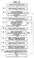
- FIG. 15 is a flowchart showing a reproduction process carried out by the sequencer 32 of the hardware tone generator 15, for reproducing the tone generator control register data having the first data structure.
- the data decoder circuit 32b reads out a first byte from the FIFO 31. Then, at a step S2, the data decoder circuit 32b determines whether or not the read data is a time management information-discriminating address. If the first data is FFh, and hence the time management information-discriminating address, the answer to this question is affirmative (YES), and hence the process proceeds to a step S3, wherein the decoder circuit 32b reads out the following one byte of data from the FIFO 31. Since the read data is time management information, it is set to the counter 32a.
- a step S4 it is determined whether or not a time period indicated by the time management information set to the counter 32a has elapsed. If the time period has not elapsed, the process waits for the time period to elapse, and when it is determined that the time period has elapsed, the process proceeds to a step S5. It should be noted that it is determined that the time period has elapsed when the count of the counter 32a becomes equal to or larger than a value indicated by the time management information.
- the data decoder circuit 32b reads out another subsequent byte of data from the FIFO 31. Then, the data decoder circuit 32b determines at a step S6 whether or not the read data is the time management information-discriminating address. If it is determined here that the read data is not the time management information-discriminating address (FFh), the process proceeds to a step S7, wherein the read data is sent to the tone generator control register 33a. However, this data is an index, which designates the address of a register provided in the tone generator control register 33a .
- the data decoder circuit 32b reads out another subsequent byte of data from the FIFO 31, and the read data forms a pair with the index sent at the step S7, and at a step S9, the data is written into a register of the tone generator control register 33a designated by the index.
- the first data sent to the tone generator register 33a are the pair constituted by the index 18h and the data "10h" in the case of the example shown in FIGS. 9 and 10.
- the sequencer terminating data is defined as data formed by the index 01h and the data "00h", as shown in FIGS. 9 and 10. If the read data are the pair of the index 01h and the data "00h", it is determined that the read data provide the sequencer terminating data, and the reproduction process is terminated. Further, if it is determined that the read data do not provide the sequencer terminating data, the process returns to the step S5, wherein the data decoder circuit 32b reads out a still another subsequent byte of data from the FIFO 31.
- the data decoder circuit 32b determines, at the step S6, whether or not the read data is the time management information-discriminating address. If it is determined that the read data is the time management information-discriminating address (FFh), the process returns to the step S3, wherein the data decoder circuit 32b reads out a still another subsequent byte of data from the FIFO 31. The data read out this time is the time management information, which is then set to the counter 32a. Then, it is determined at the step S4 whether or not a time period indicated by the time management information set to the counter 32a at the step S4 has elapsed. If the answer to this question is negative (NO), the process waits for the time period to elapse, and when it is determined that the time period has elapsed, the process proceeds to the step S5.
- FFh time management information-discriminating address
- the tone generator section 33 can be controlled in respect of the key-on/key-off, the pitch of a musical tone to be sounded, the volume, the tone color, and so forth. Further, if the data decoder circuit 32b determines at the step S2 that the read data is not the time management information-discriminating address, it is determined that the data does not belong to the tone generator control register data having the first data structure, followed by terminating the reproduction process. Further, although not shown in the flowchart, also when an error of reading data from the FIFO 31 occurs, the reproduction process is terminated.
- FIG. 16 is a flowchart showing a reproduction process carried out by the sequencer 32 of the hardware tone generator 15, for reproducing the tone generator control register data having the second data structure.
- the reproduction process is started, and at a step S21, the data decoder circuit 32b reads out a first byte from the FIFO 31. Then, at a step S22, it is determined whether or not the MSB of the read data is "1". If it is determined that the MSB of the read datais "1", it is determined that time management information is formed by two bytes, and the process proceeds to a step S23, wherein the data decoder circuit 32b reads out the following one byte of data from the FIFO 31. The read time management information composed of two bytes is set to the counter 32a.
- the read one byte of time management information is set to the counter 32a. Then, at a step S24, it is determined whether or not a time period indicated by the time management information set to the counter 32a has elapsed. If it is determined that the time period has not elapsed, the process waits for the time period to elapses, whereas if it is determined that the time period has elapsed, the process proceeds to a step S25. It should be noted that it is determined that the time period has elapsed when the count of the counter 32a becomes equal to or larger than a value indicated by the time management information set to the counter 32a.
- the data decoder circuit 32b reads out another subsequent byte of data from the FIFO 31.
- the read two bytes are data following the time management information, and as shown in FIG. 12, provide an index and data, respectively. Accordingly, the read two bytes are sent to the tone generator control register 33a.
- the data following the index is written into a register of the tone generator control register 33a designated by the index.
- the first data sent to the tone generator control register 33a are, in the example shown in FIGS. 13 and 14, a pair of data formed by the index 18h and the data "10h".
- a step S27 it is determined at a step S27 whether or not the two bytes of data read at the step S25 are the sequencer terminating data.
- the sequencer terminating data are, as described above, formed by a pair of the index 01h and the data "00h", as shown in FIGS. 13 and 14. Therefore, if the pair of read data are the index 01h and the data "00h", it is determined that they are the sequencer terminating data, followed by terminating the reproduction process. On the other hand, if it is determined that the read two bytes are not the sequencer terminating data, the process returns to the step S21, and the processing described above is repeatedly carried out.
- time management and the transfer of data to the tone generator control register 33a are carried out. Further, the time management is carried out by separating the time management information from the hardware tone generator control data read out from the FIFO 31 to set the same to the counter 32a, and monitoring a result of comparison between a value indicated by the set time management information and the count of the counter 32a. This makes it possible to simplify the construction of hardware for time management, and also reduce the size of the circuit therefor. Further, data can be sent to the tone generator control register 33a, simply in response to the register write-permitting signal delivered when the count of the counter 32a becomes equal to or larger than the value indicated by the time management information. This also makes it possible to simplify the construction of hardware therefor, and reduce the size of the circuit of the sequencer 32.
- sequencer start signal g causes the counter 32a to start counting, and at the same time, sets "1" to the bit D0 (start) of the register 01h as part of the tone generator control register 33a.
- a level signal may be used as the sequencer start signal g , whereby the apparatus may be configured such that the counting of the counter 32a is started depending on the level of the sequencer start signal g , and at the same time "1" is set to the D0 of the register 01h.
- the sequencer start signal g may contain data formed by the index "01h” and data "01h”, and by this data, "1" may be set to the D0 (start) of the register 01h.
- FIG. 17 shows the arrangement of a musical tone-generating apparatus according to a second embodiment of the invention, which is capable of reproducing a musical piece starting with a desired point thereof, and incorporated in a cellular phone 1 according to the second embodiment.
- the musical tone-generating apparatus shown in FIG. 17 includes a register area 11c provided in the RAM 11.
- the register area 11c stores performance start point data indicative of a performance start point from which the reproduction of a musical piece is started.
- This embodiment is distinguished in configuration from the FIG. 2 musical tone-generating apparatus according to the first embodiment in this respect. Therefore, in the following, the description will be given only of this configuration which distinguishes the present embodiment from the first embodiment.
- the register area in the RAM 11 stores the performance start point data indicative of a performance start point from which reproduction of a musical piece is to be started.
- the present apparatus is configured such that the user can configure the performance start point data as he desires.
- This data is configured from a menu provided in the cellular phone 1 by setting a point of a musical piece selected as an incoming call music or a music-on-hold, from which the reproduction of the musical piece is started.
- the performance start point may be set by inserting a plurality of marks in music contents data or hardware tone generator control data converted from the music contents data at respective points suitable for starting the performance of the musical piece, in advance, and selecting one of the points indicated by the marks as the start point.
- the points where the marks are inserted are e.g.
- the CPU10 causes the hardware tone generator control data-converting means 10b to convert the music contents data of the selected musical piece to hardware tone generator control data.
- the converted hardware tone generator control data are stored in the area 11b of the RAM11.
- the CPU 10 reads out the performance start point data stored in the register area 11c of the RAM 11, and starts to read hardware tone generator control data in the area 11b of the RAM 11, starting with a point corresponding to the performance start point data, followed by sequentially sending the read data to the hardware tone generator 15.
- the tone generator 33 starts generation of musical tones stating with a point indicated by the performance start point data, based on the received hardware tone generator control data. It should be noted that if there exist setup data, such as tone color data, tempo data and volume data, at the head of the music contents data, the setup data are also converted to the hardware tone generator control data and stored in advance in the area 11b of the RAM 11.
- the hardware tone generator control data corresponding to the setup data are read out from the area 11b, and transferred to the hardware tone generator 15.
- the hardware tone generator control data are read out starting with the point indicated by the performance start point data, and sequentially transferred to the hardware tone generator 15.
- the stoppage of the reproduction of a musical piece is instructed by operating an incoming call button or the like, information of a terminating point is stored so as to enable the reproduction of the musical piece to be resumed next time from a point at which the reproduction of the musical piece was terminated.
- the performance start point data is set to a first one of start points indicated by respective ones of the above-mentioned marks and located at respective positions following the point at which the reproduction of the musical piece was terminated, the performance of the musical piece can be resumed at a suitable point.
- the stoppage of the reproduction is instructed when the incoming call button of the input section 17 of the cellular phone is operated, the operation for canceling a call hold is carried out, or when the connection of the communication line is cut off.
- the performance start point data stored in the register area 11c there are used address data of respective performance start points set to the tone generator hardware control data converted from the music contents data. This makes impossible to dispense with the need of converting the music contents data from the performance start point, to the hardware tone generator control data each time the performance start point is changed.
- the performance start point data stored in the register area 11c of is initialized. Further, when a change in incoming call music is instructed as well, the performance start point data stored in the register area 11c of is initialized.
- FIG. 18 shows a musical tone-generating apparatus according to a third embodiment, which is incorporated in a cellular phone 1 according to the third embodiment.
- the musical tone-generating apparatus shown in FIG. 18 is capable of reducing the amount of converted hardware tone generator control data, and the present embodiment is distinguished from the FIG. 2 musical tone-generating apparatus according to the first embodiment in this respect. Therefore, in the following, the description will be given only of this configuration which distinguishes the present embodiment from the first embodiment.
- the RAM 11 stores MID data, SMAF data and the like, formed as files, in an area 11a thereof. Further, when the CPU 10 has extra capability of processing or available processing time, the CPU 10 reads out musical contents data from the area 11a of the RAM 11 and carries out a converting process for converting the read data to hardware tone generator control data, to store the converted hardware tone generator control data in an area 11b of the RAM 11.
- the area 11a can store musical contents data of a plurality of musical pieces, and the area lib can also store hardware tone generator control data of a plurality of musical pieces.
- FIG. 19 shows an example (third example) of hardware tone generator control data converted by the FIG. 18 musical tone-generating apparatus from SMAF data.
- the hardware tone generator control data is formed of time management information corresponding to duration and gate time, and tone generator control register write data.
- the index is information, as described hereinabove, which indicates an address of each register provided in the tone generator control register 33a, and the data following the index is written into the register indicated by the address.
- the FIG. 18 musical tone-generating apparatus is characterized in that as shown in a second line of hardware tone generator control data shown in FIG.
- the index can be represented by a plurality of bytes (two bytes in the illustrated example), and data can be expressed by a plurality of bytes (three bytes in the illustrated example), and further, as shown in a third line of the same, time management information can be represented by a plurality of bytes (two bytes in the illustrated example).
- the MSB of each byte is used to indicate whether or not there is a continued byte, so that the number of bits which can be used for expression of time is the remaining seven bits less significant than the MSB, so that a range of values of 0 to 163383 (2 14 - 1) can be expressed. Further, if the time management information is configured such that it can be represented by the maximum three bytes, it is possible to express a time period longer than the range of 0 to 16383 milliseconds.
- the index is configured such that it can be represented by a plurality of bytes for the following reasons:
- the MSB of each byte is used to indicate whether there is a continued byte, so that bits in each byte available for representation of each index are the seven less significant bits of the byte.
- the seven less significant bits of one byte can only express up to "7Fh".
- the index is expressed in two bytes, e.g.
- FIG. 18 musical tone-generating apparatus is configured such that the index can be represented by the maximum three bytes for allowance purposes.
- the data is configured such that it can be represented by three bytes so as to enable tone generator control register write data corresponding to a plurality of events to be expressed in a line, in the event that events of the same kind occur for a plurality of channels at timing having an identical value of time management information.
- the addresses into which data of events of the same kind are written are successive addresses as shown in the FIG. 7 tone generator control register map, and by making use of this, tone generator control register write data corresponding to a plurality of events can be expressed in one line.
- tone generator control register write data corresponding to a plurality of events An example of expression of tone generator control register write data corresponding to a plurality of events will be explained with reference to FIG. 20.
- FIG. 20 shows SMAF data and hardware tone generator control data converted from the SMAF data for comparison with each other.
- Duration data "00” and an event “00 37 7F” which is a channel volume message for a "channel number 0" at a first line of the SMAF data are converted to time management information "80h", an index "60h”, and data "9Fh”.
- duration data "00” and an event “00 77 55" which is a channel volume message for a "channel number 1" at a second line of the SMAF data are converted to time management information "80h", an index "61h 81h” and data "95h”.
- duration data "00” and an event “00 F7 28" which is a channel volume message for a "channel number 2" at a third line of the SMAF data are converted to time management information "80h”, index "62h 81h”, and data "85h”.
- duration data "00” and an event “00 F7 28" which is a channel volume message for a "channel number 3" at a fourth line of the SMAF data are converted to time management information "80h”, an index "63h 81h”, and data "8Ah”.
- the index data can be expressed by one byte or a plurality of bytes, i.e. two bytes or three bytes, and in this case, the significant or effective bits of each byte are the seven less significant bits thereof as described above.
- the first byte of the index data shown in FIG. 20 is "60h", and the MSB thereof is "0", which indicates that a higher-order index byte follows.
- the index byte following the first byte is "81h”, and the MSB of this byte is "1", which indicates that this byte is the highest-order byte.
- the index is represented by a plurality of index bytes, they are read in the order of a lowest-order byte to a highest-order byte.
- these bytes are rearranged in the order of the lowest-order byte to the highest-order byte, to provide index data "81h 61h", and each of the indexes (addresses of registers) generated therefrom is expressed by the less significant seven bits of a corresponding one of the bytes, to give "00 0000 1110 0000" in binary notation. Therefore, the significant bits are the less significant eight bits. If the less significant eight bits are expressed in hexadecimal notation, "E0h" is obtained.
- the index data "60h 81h” means the index "E0h”
- the index "61h 81h” is represented by an index “E1h”
- the index "62h 81h” by an index “E2h”
- the index "63h 81h” by an index "E3h”.
- Time management information is set to an identical value "80h”.
- the time management information data can be also expressed by a plurality of bytes, and if the MSB of a byte of the time management information data is "0", this indicates that a time management information byte of a higher order follows, and if the MSB of the same is set to "1", this indicates that it is a time management information byte of the highest order.
- the significant bits of each byte are the less significant seven bits. That is, the time management information data at each of a first line to a fourth line in FIG. 20 is set to "80h", which is the highest-order byte, and time management information generated from the time management information data is "00h" formed by the less significant seven bits of the same. This time management information is set to the timer 32a of the sequencer 32.
- SMAF data represented by a plurality of lines can be represented by a line of hardware tone generator control data. More specifically, as shown in a portion indicated by an arrow in FIG. 20, the first to fourth lines of the FIG. 20 SMAF data can be converted to a line of hardware tone generator control data, i.e. time management data "80h", index data "60h 81h”, and data "1Fh 15h 05h 8Ah".
- the index is set to a first one of the successive indexes, and the following data are converted to the less significant seven bits, which are effective or significant, of each byte except the last one of them. More specifically, the first data “9Fh” is converted to data “1Fh”, the second data “95h” to data "15h”, and the third data “85h” to data "05h”.
- the fourth data "8Ah” remains unchanged, so as to indicate that the fourth data "8Ah” is the last data byte by setting the MSB of the one line of hardware tone generator control data to "1". However, the data value of the fourth data is "0Ah” which is a portion exclusive of the MSB.
- the plurality of lines of SMAF data can be expressed by a line of hardware tone generator control data, so that the amount of the hardware tone generator control data can be reduced.
- FIG. 18 musical tone-generating apparatus according to the third embodiment will be described with reference to FIGS. 21 to 24.
- the counter 32a delivers the data decode start signal a to the data decode circuit 32b, thereby starting the reproduction start process.
- the time management information portion process is executed by the data decode circuit 32b, to generate time management information based on the time management information data read from the FIFO 31 one byte by one byte and set the generated time management information to the counter 32a.
- the time management information data is formed by one byte to three bytes.
- a step S31 it is determined whether or not a time period indicated by the time management information set to the counter 32a has elapsed. If it is determined that the time period has not elapsed, the process waits for the counter 32a to count up to a value corresponding to the time period, and when it is determined that the time period has elapsed, the process proceeds to a step S32. It should be noted that it is determined that the time period has elapsed when the count of the counter 32 becomes equal to or larger than a value indicated by the set time management information, and when the time period has elapsed, the counter 32a delivers the register write permission signal d to the register write controller 32c.
- an address portion process is carried out.
- the address portion process is executed by operations of the data decode circuit 32b and the address controller 32d.
- the address controller 32d based on the index data read from the FIFO 31 one byte by one byte, the address controller 32d carries out address control to generate addresses of the register in which the following data are to be written.
- the index data is formed by one byte to three bytes.
- step S33 When an address is generated at the step S32, the process proceeds to a step S33, wherein a data portion process, described in detail hereinafter, is carried out.
- the data portion process is executed by operations of the data decode circuit 32b, the address controller 32d, and the register write controller 32c, and data read from the FIFO 31 one byte by one byte are written into the tone generator control register 33a.
- each data is formed by one byte to three bytes.
- the data written into the tone generator control register 33a are data for generation of musical tones, which are used by the tone generator 33 to generate musical tones.
- the data portion process is executed after the step S31, so that data for generation of musical tones are written into the tone generator control register 33a when it is a time indicated by the time management information, so that musical tones are generate at the time indicated by the time management information.
- the process returns to a step S30, and thereafter, the steps S30 to S33 are repeatedly carried out to sequentially read hardware tone generator control data converted from the SMAF data, and the tone generator 33 carries out automatic performance.
- the data decode circuit 32b reads one byte of hardware tone generator control data from the FIFO 31.
- the read hardware tone generator control data is time management information data which is the first data of the hardware tone generator control data, or time management information data following data whose MSB is "1".
- step S42 the read one byte of the time management information data is written into a temporary register for the first byte of the time management information data.
- step S43 the data decode circuit 32b reads one byte of the time management information data from the FIFO 31.
- step S44 it is determined at a step S44 whether or not the MSB of the read second byte of the time management information data is "1". If it is determined here that the MSB is "0", this means that there continues another byte of the time management information data of a higher order, and hence the program proceeds to a step S45, wherein the read second byte of the time management information data is written into a temporary register for the second byte of the time management information data. Then, at a step S46, the data decode circuit 32b reads a still another continued byte of the time management information data from the FIFO 31. Then, it is determined at a step S47 whether or not the MSB of the read one byte of the time management information data is "1".
- the time management information data is configured to be formed by three bytes at the maximum, and hence if it is determined that the MBS is "0", this means that an error occurred. Therefore, when the MSB is determined to be "0", error handling is carried out and then the process returns to the step S31 of the reproduction start process.
- the read first byte of the time management information data is a byte of the highest order, and hence at a step S48, time management information is generated from the less significant seven bits of the read one byte, and set to the timer 32a. Then, at a step S49, all the temporary registers are cleared, and the process returns to the step S31 of the reproduction start process.
- step S44 determines that the MSB is "1"
- time management information is generated from the less significant seven bits of each byte by setting the second byte of the time management information data to the higher-order byte, and the first byte of the time management information data stored in the temporary register therefor to the lower-order byte.
- the generated time management information is set to the timer 32a.
- step S49 all the temporary registers are cleared, and the process returns to the step S31 of the reproduction start process.
- time management information is generated from the less significant seven bits of each byte by setting the third byte of the time management information data to the highest-order byte, the second byte of the time management information data stored in the temporary register therefor to the medium-order byte, and the first byte of the time management information data stored in the temporary register therefor to the lowest-order byte.
- the generated time management information is set to the timer 32a. Then, at the step S49, all the temporary registers are cleared, and the process returns to the step S31 of the reproduction start process.
- Example of the time management information portion process will be given in the following: Let it be assumed, for instance, that a data row of the time management information data is "03h 37h 81h". Then, the MSB of the first byte “03h” first read from the FIFO 31 is "0", and hence at the step S42, the read one-byte data "03h” is written into the temporary register therefor. Further, the MSB of the following one-byte data "37h” read from the FIFO 31 is also "0", and hence at the step S45, the data "37h” is written into the temporary register therefor.
- the MSB of the further following one byte of data "81h” read from the FIFO 31 is "1", and the read data "81h” is determined to be a byte of the highest order.
- the step S48 by setting the data "81h” to the highest-order byte, the data "37h” stored in the temporary register for the second byte of the time management information data to the medium-order byte, and the data stored in the temporary register for the first byte of the time management information data to the lowest-order byte, the less significant seven bits of each byte are combined to form "00h 5Bh, 83h".
- the generated time management information "0h 5Bh 83h" is set to the counter 32a.
- the data decoder circuit 32b reads one byte of hardware tone generator control data from the FIFO 31.
- the read hardware tone generator control data is a data following the time management information data, and hence index data.
- the data decoder circuit 32b reads in a following second byte of the index data from the FIFO 31.
- step S54 it is determined at a step S54, whether or not the MSB of the read second byte of the index data is "1". If it is determined here that the MSB is "0", this means that there follows another index data byte of a higher order, and hence at a step S55, the read second byte of the index data is written into a temporary register for the second byte of the index data. Then, at a step S56, the data decode circuit 32b reads in a still another following third byte of the index data from the FIFO 31. Then, at a step S57, it is determined whether or not the MSB of the read third byte of the index data is "1".
- the index data byte is configured to be formed by three bytes at the maximum, and hence if it is determined that the MSB is "0", this means that an error has occurred. Therefore, if it is determined that the MSB is "0", error handling is carried out, and then the process returns to the step S33 of the reproduction start process.
- the read first byte of the index data is the highest-order byte, and hence at a step S58, the read first byte of the index data is transferred to the address controller 32d.
- the address controller 32d generates an address for a register of the tone generator control register 33a, based on the less significant seven bits of the index data received, and supplies the address to the tone generator control register 33a, whereby the data supplied from the register write controller is written into this address. Then, at a step S59, all the temporary registers are cleared, and the process returns to the step S33 of the reproduction start process.
- the second byte of the index data read at the step S53 is a byte of the highest order, and hence the second byte of the index data, which is the higher-order byte of the two read bytes, and the first byte of the index data stored in the temporary register, which is the lower-order byte of the same, are transferred to the address controller 32d, at the step S58.
- the address controller 32d generates an address for a register of the tone generator register 33a from the less significant seven bits of each byte of the index data of the received two bytes.
- the address is supplied to the tone generator control register 33a, and data supplied from the register write controller is written into the register having the address.
- all the temporary registers are cleared, and the process returns to the step S33 of the reproduction start process.
- the third byte of the index data read at the step S56 is a byte of the highest order, and hence the third byte of the index data, which is the highest-order byte, the second byte stored in the temporary register for the second byte of the index data, which is the medium-order byte, and the first byte stored in the temporary register for the first byte of the index data, which is the lowest-order byte are transferred to the address controller 32d at the step S58.
- the address controller 32d generates an address for a register of the tone generator control register 32a from the less significant seven bits of each of the received three bytes. This address is supplied to the tone generator control register 33a and the data supplied from the register write controller 32c is written into the register having the address. Then, all the temporary registers are cleared at the step S59, and the process returns to the step S33 of the reproduction start process.
- the data decode circuit 32b reads one byte of hardware tone generator control data from the FIFO 31.
- the read hardware tone generator control data is data for generation of musical tones, which follows the index data, and hence is supplied to the register write controller 32c at a step S61.
- the register write controller 32c writes the supplied data into the tone generator control register 33a in timing in which the register write permission signal d is received from the counter 32a.
- the address controller 32d has already supplied the address of a register into which the data is to be written to the tone generator control register 33a by the address portion process at the step S32.
- the register write permission signal d has already been delivered from the counter 32a by the process at the step S31 of the reproduction start signal. Therefore, the register write controller 32c immediately writes the data into the register having the address delivered from the address controller 32d.
- the data decoder circuit 32b determines at a step S62 whether or not the MSB of the read one byte of data is "1". If it is determined here that the MSB is "0", this means that there is another following data byte, and hence the program proceeds to a step S63, wherein the data decoder circuit 32b instructs the address controller 32d to increment the present address by 1. Responsive to this instruction, the address controller 32d increments the present address by 1, and the resulting address is applied to the tone generator control register 33a. This is because, as described hereinabove, if the data is formed by a plurality of bytes, each byte of data has time management information having an identical value, and the indexes i.e. addresses are continuous.
- the process returns to the step S60, wherein the data decode circuit 32b reads another continuing one byte of data from the FIFO 31.
- the read data is supplied to the register write controller 32c at the step S61, and since the register write permission signal d has already been received from the counter 32a, the register write controller 32c immediately writes the continuing data into a register of the tone generator control register 33a having the incremented address.
- the data decoder circuit 32b determines whether or not the MSB of the continuously read one byte of data is "1". If it is determined here that the MSB is "0", this means that there follows another data byte, and hence the program proceeds to the step S63, wherein the data decoder circuit 32b instructs the address controller to increment the present address by 1. Responsive to this instruction, the address controller 32d further increments the address by 1, and applies the resulting address to the tone generator control register 33a.
- the process returns to the step S60 wherein the data decoder circuit 32b reads in a still another continuing byte of data from the FIFO 31.
- the read data is supplied at the step S61 to the register write controller 32c, and since the register write permission signal d has already been received from the counter 32a, the register write controller 32c immediately writes the read one-byte data into a register of the tone generator control register 33a having the further incremented address. Then, the data decode circuit 32b determines whether or not the MSB of the continuously read one byte of data is "1". If it is determined here that the MSB is "1", this means the read data is a final data, and hence the process returns to the step S30 of the reproduction start process.
- the MSB of one-byte data read from the FIFO 31 is used as a flag. Therefore, in carrying out the above processing dependent on the value of a register in which the one-byte data read from the FIFO 31 is written, the MSB of the register may be masked or ignored to pay attention to the less significant seven bits.
- the hardware tone generator control data-converting means 10b converts music contents data stored in the area 11a of the RAM 11 to hardware tone generator control data. As shown in the example illustrated in FIG. 20, when time management information is identical in value and indexes assume successive values, the conversion process is carried out such that tone generator control register write data corresponding to a plurality of events are expressed in a line.
- the CPU 10 When the reproduction is instructed, the CPU 10 reads hardware tone generator control data corresponding to a musical piece the reproduction of which is instructed, from the area lib of the RAM 11, and sequentially sends the read data to the hardware tone generator 15.
- the tone generator 33 generates musical tones based on the received hardware tone generator control data. It should be noted that if there exist setup data, such as tone color data, tempo data and volume data, at the head of music contents data, the setup data are also converted to the hardware tone generator control data and stored in advance in the area 11b of the RAM 11. Then, when the reproduction of the musical piece is instructed, first, the hardware tone generator control data corresponding to the setup data are read out from the area 11b, and transferred to the hardware tone generator 15. In succession thereto, the hardware tone generator control data are read out from the area 11b and sequentially transferred to the hardware tone generator 15.
- the data decode circuit 32b decodes the hardware tone generator control data read in via the FIFO 31 to separate time management information data therefrom, and from the time management information data, generates time management information, which is set to the counter 32a.
- the generation of the time management information is carried out by the time management information portion process shown in FIG. 22, and hence time management information can be generated even if the time management information data is formed by a plurality of bytes.
- the data decode circuit 32b controls the address controller 32d such that based on index data following the time management information data, addresses of registers of the tone generator control register 33a into which data further following the index data are to be written are generated.
- the generation of such addresses is carried out by the address portion process shown in FIG. 23, and hence the addresses can be generated even if the index data is formed by a plurality of bytes.
- the data decode circuit 32b supplies data for generation of musical tones, which follow the index data, to the register write controller 32c, and the register write controller 32c writes the data supplied to the tone generator control register 33a into the addresses designated by the address controller 32d in timing of delivery of the register write permission signal d at a time corresponding to the time management information set to the counter 32a.
- the writing of data into the tone generator control register 33a is carried out by the data portion process shown in FIG. 24, and hence when the data is formed by a plurality of bytes, each byte of data is written into a corresponding register of the tone generator control register 33a, while sequentially incrementing the address indicative of the register by 1.
- the musical tone-generating apparatus of the present invention when the musical tone-generating apparatus of the present invention is applied to a cellular phone as a mobile terminal apparatus according to the invention, when new music contents are downloaded into the cellular phone 1 from a download center or the like via the base station 2, it is possible to convert the downloaded musical contents to the hardware tone generator control data as described above, for reproduction of the contents. Further, when the cellular phone receives an incoming call, hardware tone generator control data corresponding to a predetermined musical piece designated for the incoming call music are read out from the RAM 11, for reproduction, whereby the incoming call music can be sounded.
- the musical tone-generating apparatus of the present invention is not necessarily applied only to the cellular phone as the mobile terminal apparatus, but it may be also applied to a mobile information terminal capable of outputting musical tones, a mobile personal computer capable of outputting musical tones, etc.
- music contents data may be reproduced in synchronism with text data or image contents data.
- the tone generator section 33 of the hardware tone generator 15 may be formed by a tone generator of frequency modulation (FM) type.
- the FM tone generator utilizes harmonics generated by frequency modulation, for synthesis of musical tones, and is capable of generating a waveform containing harmonics components including harmonic tones.
- the FM tone generator is capable of generating a wide range of musical tones ranging from a synthesized sound of a natural musical instrument to an electronic sound.
- the FM tone generator uses an oscillator called "operator", which generates sinusoidal waves by oscillation in an equivalent manner, and for example, the FM tone generator can be constructed by connecting a first operator and a second operator by cascade connection. Further, the FM tone generator may be constructed by inputting an output from the operator to itself in a feedback manner.
- the tone generation method of the tone generator section is not limited to the FM tone generation method, but there may be employed a waveform memory tone generator (PCM tone generator, ADPCM tone generator) method, a physical model tone generator method, and so forth.
- PCM tone generator PCM tone generator, ADPCM tone generator
- the tone generator may be formed by a hardware tone generator implemented by DSP or the like.
- the object of the present invention may be accomplished by supplying a storage medium in which is stored a software program realizing the functions of the above-mentioned embodiments to a system or apparatus, and causing a computer (CPU or MPU) of the system or apparatus to read out and execute the program stored in the storage medium.
- a computer CPU or MPU
- the code of the program itself read out from the storage medium achieves the novel functions of the above embodiments, and the storage medium storing the program constitutes the present invention.
- the storage medium for supplying the program to the system or apparatus may be in the form of a floppy disk, a hard disk, an optical memory disk, an magneto-optical disk, a CD-ROM, a CD-R (CD-Recordable), DVD-ROM, a semiconductor memory, a magnetic tape, a nonvolatile memory card, or a ROM, for instance.
- the program code may be supplied from a server computer via a MIDI apparatus or a communication network.
- a CPU or the like arranged in the function extension board or the function extension unit may carry out part or whole of actual processing in response to the instructions of the code of the next program, thereby making it possible to achieve the functions of the above embodiments.
- the musical tone-generating apparatus converts music contents data to hardware tone generator control data by a conversion processing device realized by software, and carries out time management by a hardware tone generator. Therefore, the musical tone-generating apparatus can be suitably applied to a mobile terminal apparatus and the like which use a small-sized circuit for a sequencer of the hardware tone generator, and does not use a high-speed CPU.
Landscapes
- Engineering & Computer Science (AREA)
- Physics & Mathematics (AREA)
- Acoustics & Sound (AREA)
- Multimedia (AREA)
- General Engineering & Computer Science (AREA)
- Electrophonic Musical Instruments (AREA)
- Mobile Radio Communication Systems (AREA)
- Telephone Function (AREA)
Abstract
There are provided a musical tone-generating
apparatus which neither requires hardware having an
increased circuit size nor imposes a heavy burden on a
CPU thereof, and a mobile terminal apparatus including
the musical tone-generating apparatus, as well as a
musical tone-generating method, and a storage medium
storing a program for executing the method. A CPU
converts music contents data stored in a RAM to hardware
tone generator control data, stores the resulting data
into the RAM. In reproduction, the CPU reads out and
sends the hardware tone generator control data to a
hardware tone generator. A data decoder circuit of the
hardware tone generator sequentially reads out the
hardware tone generator control data from a FIFO and
separates the read data into time management information
and data of a parameter for generation of a musical tone,
and sets the time management information to a counter.
Under the control of the counter performing the time
management, a register write controller writes data of
the parameter into a tone generator control register at
timing indicated by the time management information. A
tone generator section produces the musical tone based on
the data stored in the tone generator control register.
Description
This invention relates to a musical tone-generating
apparatus which has a simple construction and is capable
of generating melodies, a mobile terminal apparatus, a
musical tone-generating method, and a storage medium
storing a program for executing the method.
Conventional musical tone-generating apparatuses
include a hardware musical tone-generating apparatus
which uses hardware to generate musical tones, and a
software musical tone-generating apparatus which causes a
computer to execute a musical tone-generating program to
generate musical tones.
FIG. 25 shows an example of the arrangement of the
conventional hardware musical tone-generating apparatus.
In FIG. 25, a CPU (Central Processing Unit) 110 supplies
music contents data 111, such as MIDI (Musical Instrument
Digital Interface) data and SMAF (Synthetic Music Mobile
Application Format) data, referred to hereinafter, to a
hardware tone generator 115. In this case, the MIDI data
and SMAF data may be transferred from the outside of the
apparatus, or read from a storage means of the apparatus.
The hardware tone generator 115 includes a sequencer 132,
and a tone generator section implemented by hardware.
The sequencer 132 has hardware-specific control data-generating
section 132a which converts the MIDI data and
the SMAF data to control data specific to the hardware
tone generator 115, and a time management section 132b
which manages the timing of sounding musical tones based
on time management information contained in the data.
In the hardware musical tone-generating apparatus
constructed as above, the time management section 132b
instructs the hardware-specific control data-generating
section 132a to output data in timing based on interval
data indicative of time intervals between events
contained in the control data and gate time data
indicative of a sounding time period. Responsive to the
instruction, the hardware-specific control data-generating
section 132a delivers the hardware-specific
control data generated thereby to the tone generator
section 133. The tone generator section 133 generates
musical tones based on the supplied hardware-specific
control data. Thus, the musical tones are reproduced.
FIG. 26 shows an example of the arrangement of the
conventional software musical tone-generating apparatus.
In FIG. 26, a CPU 210 includes a sequencer function means
232 which is realized by a sequencer program executed by
the CPU 210. The sequencer means 232 is comprised of a
hardware-specific control data-generating means 210a, and
a time management means 210b. The hardware-specific
control data-generating means 210a which converts MIDI
data and SMAF data 211 to control data specific to a
hardware tone generator 215, while the time management
means 210b controls the timing of sounding musical tones.
It should be noted that the MIDI data and the SMAF data
converted by the hardware-specific control data-generating
means 210a may be transferred from the outside
of the apparatus or read from a storage means of the
apparatus. Further, the hardware tone generator 215
which generates musical tones from the hardware-specific
control data includes a tone generator section 233
implemented by hardware.
In the software musical tone-generating apparatus
thus constructed, to reproduce musical tones, the time
management means 210b of the CPU 210 instructs the
hardware-specific control data-generating means 210a to
output data in timing based on duration data indicative
of time intervals between events, arid gate time data
indicative of a sounding time period, both of which data
are contained in the converted hardware-specific control
data. Responsive to the instruction, the hardware-specific
control data-generating means 210a delivers the
hardware-specific control data generated thereby to the
hardware tone generator 215. In the hardware tone
generator 215, the tone generator section 233 generates
and outputs musical tones based on the hardware-specific
control data supplied. The musical tones are thus
reproduced by the software musical tone-generating
apparatus.
However, in the hardware musical tone-generating
apparatus which is a musical tone-generating apparatus
implemented by hardware, the sequencer 132 executes the
conversion of the musical contents data and time
management, which complicates the construction of the
sequencer 132, resulting in an increased circuit size of
the sequencer, and hence increased manufacturing costs.
Further, in the software musical tone-generating
apparatus which is a musical tone-generating apparatus
implemented by software, the CPU 210 carries out the
conversion of musical contents data and time management,
which imposes a large burden on the CPU 210, and hence a
high-speed CPU is required. Particularly, when the CPU
executes other processing with higher importance, such as
communication control, as its main function, an expensive
high-speed CPU is required to carry out the processing of
the sequencer.
Further, the conventional hardware tone-generating
apparatus and the conventional software tone-generating
apparatus starts reproduction of a musical piece from the
head thereof. This cause the inconvenience that when the
musical piece is reproduced as an incoming call music for
a cellular phone or the like, only the leading portion of
the musical piece can be heard.
It is a first object of the invention to provide a
musical tone-generating apparatus which neither requires
hardware having an increased circuit size nor imposes a
heavy burden on a CPU thereof, and a mobile terminal
apparatus including the musical tone-generating apparatus,
as well as a musical tone-generating method, and a
storage medium storing a program for executing the method.
It is a second object of the invention to enable
such a musical tone-generating apparatus and a cellular
phone to reproduce the musical piece starting with a
desired point thereof.
To attain the first object, according to a first
aspect of the invention, there is provided a musical
tone-generating apparatus comprising software process
means for converting music contents data to hardware tone
generator control data which can be reproducedand
hardware tone generator means for generating a musical
tone based on a parameter for generation of the musical
tone which is contained in the hardware tone generator
control data, whenever timing based on time management
information contained in the hardware tone generator
control data is reached.
According to this musical tone-generating apparatus,
software process means converts music contents data to
hardware tone generator control data, and time management
is executed by hardware tone generator means. Therefore,
the size of a circuit of a sequence provided in the
hardware tone generator means can be reduced. In this
case, the time management can be carried out by a
simplified construction using counter means. Further,
since the software process means is not required to
carry out processing for the time management, a burden on
the software process means can be reduced, thereby
dispensing with the use of a high-speed CPU.
Preferably, the musical tone-generating apparatus
includes storage means for storing the music contents
"data, and the software process means converts the music
contents data stored in the storage means to the hardware
tone generator control data by making use of time during
which the software process means has extra processing
capability, and stores the converted hardware tone
generator control data in the storage means.
According to this preferred embodiment, the
software process means converts the music contents data
stored in the storage means to the hardware tone
generator control data by making use of time during which
the software process means has extra processing
capability. Therefore, it is possible to prevent a load
from being concentrated on the software process means,
whereby it is possible to further reduce the needs of a
high-speed CPU.
Preferably, the hardware tone generator means
includes buffer memory means that can store a
predetermined amount of the hardware tone generator
control data, and the software process means converts
the music contents data in such an amount that the
resulting hardware tone generator control data can be
stored in the buffer memory means, and transfers the
resulting hardware tone generator control data to the
buffer memory means.
Preferably, the hardware tone generator means
includes counter means for starting counting of clocks
of a clock signal generated whenever a unit of reference
time elapses, a tone generator control register that
controls generation of the musical tone based on the
parameter for generation of the musical tone, and write
means for writing the parameter following the time
management information into the tone generator control
register when a count of the counter means becomes equal
to or larger than a value indicated by the time
management information.
To particularly attain the second object, the
musical tone-generating apparatus includes point register
means for storing data of an arbitrary performance start
point, and the hardware tone generator means generates
musical tones based on hardware tone generator control
data starting with a point corresponding to the data of
the performance start point stored in the point register
means.
According to this preferred embodiment, the musical
tone-generating apparatus includes point register means
for storing data of an arbitrary performance start point,
and musical tones are reproduced based on hardware tone
generator control data starting with a point
corresponding to the data of the performance start point
stored in the point register means. Therefore, it is
possible to reproduce a musical piece as contents data
starting with a desired point thereof. This makes it
possible to listen to the musical piece reproduced as an
incoming call music, starting with a desired point of the
musical piece.
Preferably, when the software process means converts
the music contents data to the hardware tone generator
control data, if time management information items have
an identical value, and index information items
indicative of addresses into which a parameter for
generation of a musical tone is to be written are
successive to each other, an immediately following one of
the index information items which immediately follows the
time management information items is set to a leading
index information item, and the parameter for generation
of a musical tone which follows the immediately following
index information item is formed by a plurality of
parameters corresponding to the index information items
successive to each other.
According to this preferred embodiment, if time
management information items have an identical value, and
index information items indicative of addresses into
which a parameter for generation of a musical tone is to
be written are successive to each other, an immediately
following one of the index information items which
immediately follows the time management information items
is set to a leading index information item, and the
parameter for generation of a musical tone which follows
the immediately following index information item is
formed by a plurality of parameters corresponding to the
index information items successive to each other, whereby
the amount of hardware-based tone generator control data
cab be reduced, thereby reducing the burden on the
software processing means and hardware-based tone
generator means.
More preferably, the hardware tone generator means
includes counter means for starting counting of clocks of
a clock signal generated whenever a unit of reference
time elapses, a tone generator control register that
controls generation of the musical tone based on the
parameter for generation of the musical tone, and write
means for writing the parameter following the time
management information into the tone generator control
register when a count of the counter means becomes equal
to or larger than a value indicated by the time
management information, and if the parameter is formed by
data of the plurality of parameters, writes each
parameter data into the tone generator control register
while incrementing the address indicated by the index
information one by one.
More preferably, the software process means includes
separator means for separating the hardware tone
generator control data into the parameter for generating
the musical tone and the time management information.
Further preferably, the hardware tone generator
control data is composed of units each comprising a set
of the time management information, and at least one pair
of an index designating an address of the tone generator
control register and data of the parameter to be written
into the address.
Even more preferably, each of the units of the tone
generator hardware control data is formed by the time
management information, the index, and the data of the
parameter.
Even more preferably, the time management
information includes a time management information-discriminating
address which indicates whether or not
data immediately following the time management
information-discriminating address is data of the value
indicated by the time management information.
To attain the first object, according to a second
aspect of the invention, there is provided a mobile
terminal apparatus comprising a musical tone-generating
apparatus including software process means for
converting music contents data to hardware tone generator
control data which can be reproduced, the conversion
processing device being realized by software, and
hardware tone generator means for generating a musical
tone based on a parameter for generation of the musical
tone which is contained in the hardware tone generator
control data, whenever timing based on time management
information contained in the hardware tone generator
control data is reached, and a processing device that
performs processing of mobile terminal functions, wherein
the software process means is realized by part of
functions of the processing device.
According to this mobile terminal apparatus, the
same advantageous effects as describe above can be
obtained.
To particularly attain the second object, it is
preferred that the musical tone-generating apparatus
point register means for storing data of an arbitrary
performance start point, and wherein the hardware tone
generator means generates musical tones based on hardware
tone generator control data starting with a point
corresponding to the data of the performance start point
stored in the point register means.
According to this preferred embodiment, the same
advantageous effects as describe above can be obtained.
To attain the first object, according to a third
aspect of the invention, there is provided a musical
tone-generating method comprising the steps of converting
music contents data to hardware tone generator control
data which can be reproduced, by software, and generating
a musical tone based on a parameter for generation of the
musical tone which is contained in the hardware tone
generator control data, whenever timing based on time
management information contained in the hardware tone
generator control data is reached.
According to this musical tone-generating method,
the same advantageous effects as described above can be
obtained.
To attain the first object, according to a fourth
aspect of the invention, there is provided a storage
medium storing a program for causing a computer to
execute a musical tone-generating method, the program
comprising a conversion process module that converts
music contents data to hardware tone generator control
data which can be reproduced, and a hardware tone
generator module that generates a musical tone based on a
parameter for generation of the musical tone which is
contained in the hardware tone generator control data,
whenever timing based on time management information
contained in the hardware tone generator control data is
reached.
According to this storage medium, the same
advantageous effects as described above can be obtained.
Now, the present invention will be described in
detail with reference to the drawings showing embodiments
thereof.
FIG. 1 shows an example of the configuration of a
cellular phone to which is applied a mobile terminal
apparatus provided with a musical tone-generating
apparatus according to a first embodiment of the present
invention, together with a base station.
The cellular phone 1 is provided with an antenna 25,
which is generally a retractable type and can be
connected to the base station 2 by radio. The antenna 25
is connected to a communication section 13 having a
modulating/demodulating function. A CPU (Central
Processing Unit) 10 serves as a system controller that
controls components of the cellular phone 1 by executing
a telephone function program, and includes a timer that
indicates elapsed time during operation and generates a
timer interrupt at predetermined time intervals. Further,
the CPU 10 carries out processes related to generation of
musical tones such as a data conversion process, as
described in detail hereinafter. A RAM (Random Access
Memory) 11 provides a storage area for storing music
contents data of a distribution format which are
downloaded from a download center or the like connected
via the basic station 2, a storage area for storing
hardware tone generator control data converted from the
music contents data, and a work area for the CPU 10. A
ROM (Read Only Memory) 12 stores various programs
executed by the CPU 12 such as telephone function
programs for sending or receiving a call, programs for
processes related to generation of musical tones, and
various data, such as preset hardware tone generator
control data.
The communication section 13 carries out
demodulation of a signal received at the antenna 25, as
well as modulation of a signal to be transmitted and
supplies the modulated signal to the antenna 25. The
incoming call signal demodulated by the communication
section 13 is decoded by an audio processing section
(coder/decoder) 14, and a call signal input from a
microphone 21 is compression coded by the audio
processing section 14. The audio processing section 14
subjects a sound or audio signal to high-efficiency
compression encoding/decoding, and is implemented by a
coder/decoder based on a CELP (Code Excited LPC) method
and an ADPCM (Adaptive Differential PCM encoding) method.
A hardware tone generator 15 converts the call signal
received from the audio processing section 14 into sound
to be sounded via a received message speaker 22, or
generates an incoming call music or music-on-hold by
reproducing the converted hardware tone generator control
data. It should be noted that the incoming call music is
sounded via an incoming call speaker 23, while the music-on-hold
is sounded via the received message speaker 22
after being mixed with the incoming call signal.
Further, as the format of music contents data, there
are employed a MID format and a SMAF format which are
convenient to distribution of data, and the CPU 10
converts the music contents data in these formats into
hardware tone generator control data having a format
specific to the hardware tone generator 15, whereby it is
possible to reproduce musical tones based on the data in
these formats. The converted hardware tone generator
control data can be stored in the RAM 11. The hardware
tone generator 15 reproduces musical tones based on the
hardware tone generator control data, and to this end,
has provided therein a FIFO for temporarily storing a
predetermined amount of the hardware tone generator
control data. The FIFO may have a storage capacity large
enough to store the whole of one musical piece, but if
the capacity of the FIFO is not large enough to store the
whole music piece, it may be so configured that whenever
a predetermined amount of unused area is produced in the
FIFO, the hardware tone generator 15 sends a FIFO data
request signal to the CPU 10. Responsive to this request
signal, the CPU 10 continues to read the following
portion of the hardware tone generator data stored in the
RAM 11 or ROM 12, and delivers the read data to the
hardware tone generator 15. This makes it possible to
reproduce a musical piece formed by a large amount of
hardware tone generator control data even with a small-capacity
FIFO.
Further, an interface (I/F) 16 provides interface
for downloading music contents data and the like from an
external apparatus 20, such as a personal computer. An
input section 17 is an input means comprised of dial
buttons for inputting "0" to "9", respectively, and other
buttons. A display 18 displays a menu of options for
selecting telephone functions, and images associated with
operations of respective buttons, including the dial
buttons. A vibrator 19 vibrates the body of the cellular
phone 1 upon receipt of an incoming call in place of
generating the incoming call sound. It should be noted
that all the components and sections are connected to
each other via a bus 24.
FIG. 2 shows the construction of the musical tone-generating
apparatus according to the first embodiment of
the present invention, which is used in the cellular
phone 1 as its hardware tone generator 15. In FIG. 2,
the received message speaker 22, the incoming call
speaker 23, and components associated therewith are
omitted. The CPU 10, the hardware tone generator 15, and
the RAM 11 are communicated with each other for transfer
of data therebetween by the bus 24, though not shown in
FIG. 2.
In the FIG. 2 musical tone-generating apparatus
according to the first embodiment, the RAM 11 stores MID
data, SMAF data and the like, formed as files, in an area
11a thereof. Further, when the CPU 10 has extra
capability of processing or available processing time,
the CPU 10 reads out musical contents data from the area
11a of the RAM 11 and carries out a converting process
for converting the read data to hardware tone generator
control data, to store the converted hardware tone
generator control data in an area 11b of the RAM 11. The
area 11a can store musical contents data of a plurality
of musical pieces, and the area 11b can also store
hardware tone generator control data of a plurality of
musical pieces.
As described above, the CPU 10 reads out musical
contents data from the area 11a of the RAM 11 and carries
out the converting process for converting the read data
to hardware tone generator control data, which is stored
in the area 11b of the RAM 11. The converting process is
executed by a hardware tone generator control data-generating
means 10b of the CPU 10, which is implemented
by software. When the CPU 10 converts the music contents
data to the hardware tone generator control data, a
memory controller 10a sequentially reads out music
contents data to be converted from the area 11a of the
RAM 11 starting from the leading portion of the data, and
supplies the read data to a hardware tone generator
control data-generating means 10b. The hardware tone
generator control data-generating means 10b interprets
the supplied music contents data and sequentially
converts the same to hardware tone generator control data.
The memory controller 10a sequentially writes the
hardware tone generator control data thus obtained into
the area 11b of the RAM 11. In this way, the CPU 10
converts the music contents data to the hardware tone
generator control data.
It should be noted that when the CPU 10 performs the
reproduction of musical tones while executing the data-converting
process, the memory controller 10a writes the
hardware tone generator control data f thus obtained into
a FIFO (First-In First-Out) 31 of the hardware tone
generator 15.
The hardware tone generator 15 includes the FIFO 31
capable of storing a predetermined amount of hardware
tone generator control data, and a sequencer 32
sequentially reads out the hardware tone generator
control data from the FIFO 31. The FIFO 31 is capable of
storing e.g. 32 words of the hardware control data, in a
First-In First-Out method, i.e. reads out the hardware
tone generator control data in the order in which the
data were written. When a predetermined amount of unused
area occurs in the FIFO 31 as a result of reading of the
hardware tone generator control data therefrom, the FIFO
31 sends a FIFO data request signal g to the memory
controller 10a of the CPU 10, requesting the following
hardware tone generator control data f to be transferred
to the FIFO 31. This enables reproduction of a musical
piece or pieces of a large amount of hardware tone
generator control data by using a FIFO with a small
capacity for the FIFO 31.
The sequencer 32 of the hardware tone generator 15
includes a data decoder circuit 32b, which separates the
hardware tone generator control data read out from the
FIFO 31 into time management information and tone
generator control register write data. In this case,
when a time management information-discriminating address
is added to the hardware tone generator control data in a
position immediately before the time management
information, data, which is one byte, for example,
following the time management information-discriminating
address is separated as time management information. The
remaining part of the hardware tone generator control
data other than the time management information-discriminating
address and the time management
information, that is, tone generator control register
write data provides a parameter for generating musical
tone, and is written into a tone generator control
register 33a of a tone generator section 33 under the
control of a register write controller 32c. The register
write controller 32c writes the tone generator control
register write data into the tone generator control
register 33a in timing in which a register write-permitting
signal d is outputted. The register write-permitting
signal d is outputted in timing in which the
count of a counter (timer) 32a becomes equal to a value
of duration or a value of gate time contained in the time
management information, as will be described hereinafter.
The counter 32a of the sequencer 32 counts clock
pulses output, e.g. at time intervals of 1 millisecond,
as reference time units. The counting of the clock
pulses is started when a sequencer start signal g output
from the CPU 10 is applied to the counter 32a. Further,
the sequencer start signal g instructs starting of
operation of the sequencer by writing data "01h" into a
register 01h arranged within the sequencer 32 of the tone
generator control register 33a, to thereby set "1" to a
bit D0 (start) thereof. This causes the sequencer 32 to
start sequencer processing, and when the counter 32a
starts counting, the counter 32a applies a data decode
start signal a to the data decoder circuit 32b. The data
decoder circuit 32b is responsive to the data decode
start signal a to read out hardware tone generator
control data from the FIFO 31 and then extracts the time
management information therefrom. The extracted time
management information b is sent to the counter 32a, and
when the count of the counter 32a becomes equal to or
larger than the time management information b, the
counter 32a applies the register write-permitting signal
d to the register write controller 32c to write the tone
generator control register write data c extracted by the
data decoder circuit 32b into the tone generator control
register 33a. This causes the tone generator section 33
to generate musical tones based on the tone generator
control register write data c and output the musical
tones. Then, the data decoder circuit 32b reads out the
next hardware tone generator control data from the FIFO
31.
Then, the data decoder circuit 32b extracts the next
time management information from the read hardware tone
generator control data, and the same process as described
above is repeatedly carried out. That is, when the count
of the counter 32a becomes equal to or larger than the
next time management information b, the counter 32a
applies the register write-permitting signal d to the
register write controller 32c, to write the next tone
generator control register write data c extracted by the
data decoder circuit 32b into the tone generator control
register 33a. This causes the tone generator section 33
to generate musical tones based on the next tone
generator control register write data c and output the
generated musical tones. Then, the data decoder circuit
32b reads out the second next hardware tone generator
control data from the FIFO 31. Thus, the hardware tone
generator control data is sequentially read from the FIFO
31, whereby the tone generator 33 reproduces musical
tones.
Next, the operation of the musical tone-generating
apparatus shown in FIG. 2 performed in response to an
instruction for reproduction will be described.
First, the SMAF format will be described. Data
structures of the SMAF format are shown in FIGS. 3A, 3B
and 4. As shown in FIG. 3A, the SMAF data has a chunk
structure and is comprised of a contents information
chunk (Contents Info Chunk) 40, a score track chunk 41,
and a PCM audio track chunk 42. The contents information
chunk 40 includes information and definitions of the
contents, the score track chunk 41 stores a tone
generator sequence track, and the PCM audio track chunk
42 stores compressed PCM-type audio sounding data, such
as ADPCM data, MP3 (MPEG audio layer 3) data, and TwinVQ
data, in the form of events.
The data structure of the score track chunk 41 is
shown in FIG. 3B. As shown in the figure, the score
track chunk 41 is comprised of data of a format type, a
sequence type, etc., and chunks, such as a setup data
chunk 43 and a sequence data chunk 44. The format type
data indicates a status of the data in which the actual
format of this chunk is defined, and can define the
format type as a handy phone standard type, for instance.
The sequence type data indicates one of two types of
sequence data, i.e. a stream sequencer type and a sub-sequencer
type. The setup data chunk 43 stores tone
color data, settings of effects and the like, and the
sequence data chunk 44 stores sequence data which is real
performance data.
Next, the data structure of the sequence data stored
in the sequence data chunk 44 is shown in FIG. 4. As
shown in the figure, the sequence data is comprised of
pairs of data, each pair formed by one byte of duration
data, and two or three bytes of event data, which are
arranged in an alternating manner. In this case, the
format is configured such that duration data necessarily
exists before each event data. The duration data
indicates time information indicative of a time interval
between the event immediately preceding the duration data
and an event immediately following the duration data.
Further, the events include a note message for
controlling sounding, a control message for controlling a
volume, a modulation, and the like, an exclusive message
which can carry information peculiar to a maker of the
data, etc. Further, the note message is comprised of a
channel number indicative of a designated sounding
channel, a note number indicative of a tone pitch of a
musical tone to be sounded, a gate time indicative of a
duration of sounding.
The FIG. 4 sequence data composed of duration data 1
to duration data 3 and event data 1 to event data 3 can
be expressed along the time axis as shown in FIG. 5.
Assuming that an event 1, an event 2, and an event 3 are
note messages for note on (sounding), the sounding by the
event 1 is started upon the lapse of a time period
indicated by the duration 1. Further, the sounding by
the event is stopped upon the lapse of a time period
indicated by the gate time 1 after the start of sounding
by the event 1, and then when a time period indicated by
the duration 2 has elapsed after the lapse of the time
period indicated by the duration 1, the sounding by the
event 2 is started. Then, when a time period indicated
by the gate time 2 has elapsed after the start of
sounding by the event 2, the sounding by the event 2 is
stopped. Further, when a time period indicated by the
duration 3 has elapsed after the lapse of the time period
indicated by the duration 2, the sounding by an event 3
is started. Then, when a time period indicated by the
gate time 3 has elapsed after the start of sounding by
the event 3, the sounding by the event 3 is stopped.
Hereafter, the FIG. 4 sequence data is referred to as the
"SMAF data".
Referring again to FIG. 2, the hardware tone
generator control data-generating means 10b converts
music contents data, e.g. SMAF data, to hardware tone
generator control data. Here, the hardware tone
generator control data formed by the conversion is
sequentially transferred to the hardware tone generator
15, and the tone generator section 33 generates musical
tones based on the hardware tone generator control data.
To this end, the hardware tone generator control data is
configured to have a data structure adapted to a register
map of the tone generator control register 33a of the
tone generator section 33. Here, an example of hardware
tone generator control data formed by converting the SMAF
data is shown. Although the hardware tone generator
control data contains time management information
corresponding to duration and gate time, the time
management information is not written into the tone
generator control register 33a. Tone generator control
register map-adapted data formed by eliminating the time
management information from the hardware tone generator
control data is shown in FIG. 6 in a manner associated
with the SMAF data before conversion.
In FIG. 6, duration data "00" and an event "00 30
47" of a program change message of SMAF data are
converted to an index "18h" and data "10h". In these
data, "h" indicates that the numerical value is in
hexadecimal notation. The index designates the address
of a register shown in the tone generator control
register map of the tone generator control register 33a
shown in FIG. 7, and the data following the index is
written into a register having the address indicated by
the index. In this case, each register has a capacity of
one byte, and the tone generator control register 33a has
one register to be addressed by an index "01h", eight
registers to be addressed by respective indexes "18h" to
1Fh", sixteen registers to be addressed by respective
indexes "B0h" to "BFh", sixteen registers to be addressed
by respective indexes "C0h" to "CFh", and sixteen
registers to be addressed by respective indexes "E0h" to
"EFh". It should be noted that only the register "01h"
to be addressed by the index "01h" is arranged within the
sequencer 32, as shown in FIG. 2. Further, the length of
each index is one byte, and hence each register is formed
of eight bits, for storing data having the corresponding
length of one byte.
Each of the eight registers to be addressed by the
respective indexes "18h" to "1Fh" is used for designating
a tone color number of a channel n and a tone color
number of a next channel n + 1. This enables designation
of respective tone colors of sixteen channels. Further,
each of the sixteen registers to be addressed by the
respective indexes "B0h" to "BFh" stores less significant
eight bits of an F number defined in ten bits
representative of a numerical value proportional to the
frequency of the tone pitch assigned to each key of a
keyboard. Further, each of the sixteen registers to be
addressed by the respective indexes "C0h" to "CFh" stores
the remaining more significant two bits of the F number
at respective bits D0 and D1 thereof, three bits defining
octave information at respective bits D2, D3, D4 thereof,
and key-on information at a bit D5 thereof. This makes
it possible to designate a tone pitch defined by the F
number and the octave, and key-on, for each of the
sixteen channels. Further, each of the sixteen registers
to be addressed by the respective indexes "E0h" to "EFh"
stores five bits defining channel volume information at
respective bits D0 to D4. Thus, the channel volume
information can be designated for each of the sixteen
channels.
Therefore, through conversion of the duration data
"00" and the event "00 30 47" of the program change
message of SMAF data to the index "18h" and data "10h",
the data "10h" is stored in the register 18h, whereby the
tone color having the tone color number "01h" is
designated for the channel 1, and the tone color having
the tone color number "1h" is designated for the channel
2.
Further, duration data "00" and an event "00 37 7F"
of a channel volume message of the next SMAF data are
converted to the index "E0h" and data "1Fh". The data
"1Fh" formed by the conversion is stored in the register
E0h, whereby the data "1Fh" designates the volume value
of the channel 1 as "1Fh".
Further, duration data "00" and an event "2C 50" of
a note message of the next SMAF data are converted to the
index "B0h" and data "B2h", and the index "C0h" and data
"32h". The data "B2h" formed by the conversion is stored
in the register B0h, and the data "32h" formed by the
conversion is stored in the register C0h. Ten bits
formed by 0-th to 8-th bits provided by the data "B2h"
("1010010" in binary notation) and 9-th and 10-th bits at
bits D0 and D1 of the data "32h" ("00110010" in binary
notation) designates the F number of the channel 1.
Further, the three bits "100" at respective bits D2, D3,
D4 of the data "32h" designate an octave of the channel 1.
Further, "1" at a bit D5 of the data "32h" designates
key-on of the channel 1.
Further, duration data "5C" and an event "2B 20" of
a note message of the next SMAF data are converted to the
index "B0h" and data "8Bh", and the index "C0h" and data
"32h". The data "8Bh" formed by the conversion is stored
in the register B0h, and the data "32h" formed by the
conversion is stored in the register C0h. Ten bits
"1010001011" formed by 0-th to 8-th bits provided by the
data "8Bh" ("10001011" in binary notation) and 9-th and
10-th bits at bits D0 and D1 of the data "32h"
("00110010" in binary notation) designate the F number of
the channel 1. Further, three bits "100" at bits D2, D3,
D4 of the data "32h" designate an octave of the channel 1.
Further, "1" at a bit D5 of the data "32h" designates
key-on of the channel 1.
The SMAF data and tone generator control register
map-adapted data formed by converting the SMAF data are
associated with each other as described above, and the
following data are also similarly converted.
It should be noted that the event "2C 50" of the
note message and the event "2B 20" of SMAF data are shown
in hexadecimal notation, and "50" and "20" within them
are gate time data each indicative of a time period over
which the sounding of musical tones is carried out. That
is, the sounding by these note messages must be stopped
when the reference time of "50h" or "20h" has elapsed.
That is, to effect note-off upon the lapse of the
reference time of "50h" or "20h" after the sounding was
started, there are required duration data set to "50h" or
"20h", and a not message instructing key off, with key-on/key-off
information being set to "0".
Such note messages are not shown in FIG. 6, but are
automatically generated by the hardware tone generator
control data-generating means 10b during the data
conversion, through interpretation of SMAF data before
the conversion. Therefore, for the help of explanation,
a first data structure of the hardware tone generator
control data converted from the SMAF data which includes
time management information is shown in FIG. 8, and an
example of hardware tone generator control data having
the first data structure formed by converting the FIG. 6
SMAF data is shown in FIG. 9. Further, the FIG. 9
hardware tone generator control data rearranged in sets
of data is shown in FIG. 10.
As shown in FIG. 8, in the first data structure of
the hardware tone generator control data, a time
management information-discriminating address and time
management information forms a set of data, and the time
management information-discriminating address is arranged
in a position immediately before the time management
information. That is, when the time management
information-discriminating address is detected, it is
assumed that data following the detected time management
information-discriminating address is time management
information. Following the time management information,
at least one set of data each formed by a pair of an
index and data is provided. The index is information, as
described hereinabove, which indicates an address of each
register provided in the tone generator control register
33a, and the data following the index is written into the
register indicated by the address. Further, the timing
in which the data is written into the register is
designated by the time management information arranged in
a position immediately before the at least one pair of
the index and data. The hardware tone generator control
data-generating means 10b converts the SMAF data to the
hardware tone generator control data shown in FIG. 8.
FIG. 9 shows the hardware tone generator control
data formed by the hardware tone generator control data-generating
means 10b interpreting and converting the FIG.
6 SMAF data. In the FIG. 9 hardware tone generator
control data, sequencer terminating data is also added in
addition to the time management information. That is,
the first data is set to "FFh" defined as the time
management information-discriminating address, and then
time management information "00h" as the duration data
follows. The data following the duration data are, as
described above, the set of data formed by the pair of
the index "18h" and data "10h", the set of data formed by
the pair of the index "B0h" and data "B2h" and the pair
of the index "C0h" and data "32h", and so forth. This
sequence of data designates the tone colors of the
channels 1 and 2, and the volume of the channel 1, as
well as the key-on and a tone pitch of the channel 1.
The following data is data, not shown in FIG. 6, for
terminating the sounding of musical tones reproduced via
the channel 1. The timing of start of the sounding of
the channel 1 is set to timing indicated by the time
management information "00h" arranged in a position
immediately before the sounding data. Then, the sounding
is terminated in timing of the lapse of the gate time.
In other words, the time management information of data
of which the sounding is to be stopped is a data value
corresponding to the gate time. That is, the data for
terminating the sounding is formed by a set of data
formed by a pair of "FFh" as the time management
information-discriminating address and time management
information "50h" and a set of data subsequent thereto
formed by a pair of the index "B0h" and data "B2h" and a
pair of the index "C0h" and data "12h". This data causes
the data "B2h" to be stored in the register B0h and the
data "B2h" in the register C0h upon the lapse of the
reference time "50h", whereby ten bits "1010110010"
formed by 0-th to 8-th bits formed by the data "B2h"
("10110010" in binary notation") and 9-th and 10-th bits
of "10" at bits D0 and D1 of the data "12h" ("00010010"
in binary notation) designate the F number of the channel
1. Further, three bits "100" at bits D2, D3, D4, of the
data "12h" designate the octave of the channel 1.
Further, "0" at a bit D5 of the data "12h" designates the
key-off of the channel 1. This causes the musical tone
of the channel 1 being sounded based on the designated
octave and F number to be stopped upon the lapse of the
reference time "50h".
The following data are also written in the tone
generator control register 33a. At the end of the
hardware tone generator control data, there are provided
data formed by a pair of the time management information-discriminating
address "FFh" and the time management data
"00h", and data subsequent thereto which is formed by a
pair of the index "01h" and data "00h" ("00000000" in
binary notation). In this case, the data "00h" is set to
the register 01h of the tone generator control register
33a, which is arranged within the sequencer 32, in timing
of the lapse of the reference time "01h" from the
occurrence of the immediately preceding event. This sets
"0" to the bit D0 (start) of the register 01h shown in
FIG. 7, whereby the termination of sequencer operation is
instructed to the sequencer 32. In short, the index
"01h" and data "00h" form the sequencer terminating data.
FIG. 10 shows rearrangement of the hardware tone
generator control data having the first data structure
and formed by the hardware tone generator control data-generating
means 10b through interpretation and
conversion of the SMAF data, in sets of data. As shown
in the figure, the hardware tone generator control data
having the first data structure is composed of data each
formed by a pair of a time management information-discriminating
address and time management information
and data each formed by a pair of an index and data. The
operation of the FIG. 2 musical tone-generating apparatus
performed when reproduction of a musical piece is
instructed by designating the hardware tone generator
control data thus converted from the SMAF data will be
described with reference to FIGS. 2 and 10. It is
assumed, however, that the hardware tone generator
control data has been converted from the SMAF data by the
CPU 10 and the resulting data has been stored in the area
11b of the RAM 11 prior to the reproduction of the
musical piece.
The memory controller 10a of the CPU 10 reads out
hardware tone generator control data f shown in FIG. 10
which corresponds to the musical piece designated for
reproduction from the area 11b of the RAM 1, e.g. by an
amount of 32 bytes, and transfers the same to the FIFO 31
of the hardware tone generator 15. Simultaneously, the
CPU 10 supplies the sequencer start signal g to the
counter 32a of the sequencer 32.
Further, the sequencer start signal g is written
into the register 01h as part of the tone generator
control register 33a to set "1" to the bit D0 (start)
thereof, thereby instructing the sequencer operation to
be started. This causes the sequencer 32 to start the
sequencer operation, and the counter 32a operates in
response to the sequencer start signal g to start
counting clocks as units of the reference time, and at
the same time applies the data decode start signal a to
the data decoder circuit 32b. The data decoder circuit
32b operates in response to the data decode start signal
a to read data from the FIFO 31 one byte by one byte. In
this case, when the read data is the time management
information-discriminating address "FFh", another byte is
further read out. As shown in FIG. 10, data following
the time management information-discriminating address is
time management information, and therefore, this
information is set to the counter 32a.
Further, the data decoder circuit 32b continues to
read out the following data from the FIFO 31, and the
index "18h" read out and the data "10h" read out in
succession thereto are both tone generator control
register write data, and hence sent to the register write
controller 32c. The register write controller 32c
prepares for writing the data "10h" into the register 18h
having the address indicated by the index "18h". In this
case as well, the time management information set to the
counter 32a is "00h", and hence the counter 32a instantly
applies the register write-permitting signal d to the
register write controller 32c, whereupon, responsive to
this signal, the register write controller 32c writes the
data "10h" into the register 18h of the tone generator
control register 33a. The register 18h designates the
tone cooler numbers of the channels 1 and 2, so that the
tone colors of the channels 1 and 2 of musical tones
generated from the tone generator section 33 are
designated.
Also further, the data decoder circuit 32b continues
to read out the following data from the FIFO 31, and the
index "E0h" read out and the data "1Fh" read out in
succession thereto are both tone generator control
register write data, and hence sent to the register write
controller 32c. The register write controller 32c
prepares for writing the data "1Fh" into the register E0h
having the address indicated by the index "E0h". In this
case as well, the time management information set to the
counter 32a is "00h", and hence the counter 32a instantly
applies the register write-permitting signal d to the
register write controller 32c, whereupon, responsive to
this signal, the register write controllers 32c writes the
data "1Fh" into the register E0h of the tone generator
control register 33a. The register E0h designates the
channel volume of the channel 1, so that the channel
volume of the channel 1 of a musical piece generated by
the tone generator section 33 is designated.
Further, the data decoder circuit 32b continues to
read out the following data from the FIFO 31, and the
index "B0h" read out and the data "B2h" read out in
succession thereto are both tone generator control
register write data, and hence sent to the register write
controller 32c. The register write controller 32c
prepares for writing the data "B2h" into the register B0h
having the address indicated by the index "B0h". In this
case as well, the time management information set to the
counter 32a is "00h", and hence the counter 32a instantly
applies the register write-permitting signal d to the
register write controller 32c, whereupon, responsive to
this signal, the register write controller 32c writes the
data "B2h" into the register B0h of the tone generator
control register 33a. The register B0h designates the
less significant eight bits of the F number of the
channel 1.
Further, the data decoder circuit 32b continues to
read out the following data read out from the FIFO 31,
and the read index "C0h" and the data "32h" read out in
succession thereto are both tone generator control
register write data, and hence sent to the register write
controller 32c. The register write controller 32c
prepares for writing the data "32h" into the register C0h
having the address indicated by the index "C0h". In this
case as well, the time management information set to the
counter 32a is "00h", and hence the counter 32a instantly
applies the register write-permitting signal d to the
register write controller 32c, whereupon, responsive to
this signal, the register write controller 32c writes the
data "32h" into the register C0h of the tone generator
control register 33a. The register C0h designates an
octave in cooperation with the more significant two bits
of the F number of the channel 1, and at the same time
designates the key-on/key-off of the channel 1, and "1"
is set to a bit D5 thereof (D5 = 1) to designate the key-on,
whereby the key-on of the channel 1 is designated, to
start generation of a musical tone with the tone pitch of
the octave and F number, the volume, and the tone color,
which are set in the tone generator control register 33a.
Then, the data decoder circuit 32b reads out the
following data from the FIFO 31, and the data read out is
time management information-discriminating address "FFh",
and hence the time management information "50h" read out
in succession thereto is set to the counter 32a as the
time management information b. The data decoder circuit
32b reads out the following data from the FIFO 31, and
the data read out is the index "B0h", which is tone
generator control register write data, and hence sent to
the register write controller 32c together with the data
"B2h" read out in succession thereto. The register write
controller 32c prepares for writing the data "B2h" into
the register B0h having the address indicated by the
index "B0h". In this case, the time management
information set to the counter 32a is "50h", and hence
the process waits for the counter 32a to count up to a
value corresponding to "50h".
Then, the data decoder circuit 32b reads out the
following data from the FIFO 31, and the data read out is
the index "C0h", which is tone generator control register
write data, and hence sent to the register write
controller 32c together with the data "12h" read out in
succession thereto. The register write controller 32c
prepares for writing the data "12h" into the register C0h
having the address indicated by the index "C0h". In this
case, the time management information set to the counter
32a is "50h", and hence the process waits for the counter
32a to count up to the value corresponding to "50h".
Then, the counting of the counter 32a progresses, and in
timing a time period corresponding to "50h" has elapsed
(time point 50h), the counter 32a applies the register
write-permitting signal d to the register write
controller 32c, whereupon, responsive to this signal, the
register write controller 32c writes the data "B2h" into
the register B0h of the tone generator control register
33a, and at the same time writes the data "12h" into the
register C0h. The register B0h designates the less
significant eight bits of the F number of the channel 1,
while the register C0h designates an octave in
cooperation with the more significant two bits of the F
number of the channel 1, and at the same time designates
the key-on/key-off of the channel 1, by the bit D5
thereof. In the present case, "0" is set to the bit D5
(D5 = 0) of the register C0h to designate the key-off.
This instructs the key-off of the musical tone of the
channel 1 being generated by the tone generator section
33 with the tone pitch of the designed octave and F
number, thereby stopping the generation of the musical
tone.
When the count of the counter 32a becomes equal to
or larger than the value corresponding to "50h", the data
decoder circuit 32b reads out the following data from the
FIFO 31. The read data is time management information-discriminating
address "FFh", and hence the time
management information "0Ch" read out in succession
thereto is set to the counter 32a as the time management
information b. The data decoder circuit 32b reads out
the following data from the FIFO 31, and the data read
out is the index "B0h", which is tone generator control
register write data, and hence sent to the register write
controller 32c together with the data "8Bh" read out in
succession thereto. The register write controller 32c
prepares for writing the data "8Bh" into the register B0h
having the address indicated by the index "B0h". In this
case, the time management information set to the counter
32a is "0Ch", an hence the process waits for the counter
32a to count up to a value corresponding to "0Ch".
Then, the data decoder circuit 32b reads out the
following data from the FIFO 31, and the data read out is
the index "C0h", which is tone generator control register
write data, and hence sent to the register write
controller 32c together with the data "32h" read out in
succession thereto. The register write controller 32c
prepares for writing the data "32h" into the register C0h
having the address indicated by the index "C0h". In this
case, the time management information set to the counter
32a is "0Ch", and hence the process waits for the counter
32a to count up to a value corresponding to "0Ch". Then,
the counting of the counter 32a proceeds, and in timing a
time period corresponding to "0Ch" has elapsed from the
time point "50h" (time point 5Ch (= 50h + 0Ch)) the
counter 32a applies the register write-permitting signal
d to the register write controller 32c, whereupon,
responsive to this signal, the register write controller
32c writes the data "8Bh" into the register B0h of the
tone generator control register 33a, and at the same time
writes the data "32h" into the register C0h of the same.
The register B0h designates the less significant eight
bits of the F number of the channel 1, while the register
C0h designates an octave in cooperation with the more
significant two bits of the F number of the channel 1,
and at the same time designates the key-on/key-off of the
channel 1. In this case, "1" is set to the bit D5 (D5 =
1) of the register C0h to designate the key-on. This
instructs the key-on of the musical tone of the channel 1,
whereby the key-on of the channel 1 is designated, to
start generation of a musical tone with the tone pitch of
the octave and F number, the volume, and the tone color,
which are set in the tone generator control register 33a.
Then, the data decoder circuit 32b continues to read
out the following data from the FIFO 31. The read data is
the time management information-discriminating address
"FFh", and hence the time management information "20h"
read out in succession thereto is set to the counter 32a
as the time management information b. Then, the data
decoder circuit 32b reads out the following data from the
FIFO 31, and the data read out is the index "B0h", which
is tone generator control register write data, and hence
sent to the register write controller 32c together with
the data "8Bh" read out in succession thereto. The
register write controller 32c prepares for writing the
data "8Bh" into the register B0h having the address
indicated by the index "B0h". In this case, the time
management information set to the counter 32a is "20h",
and hence the process waits for the counter 32a to count
"20h".
Then, the data decoder circuit 32b reads out the
following data from the FIFO 31, and the data read out is
the index "C0h", which is tone generator control register
write data, and hence sent to the register write
controller 32c together with the data "12h" read out in
succession thereto. The register write controller 32c
prepares for writing the data "12h" into the register C0h
having the address indicated by the index "C0h". In this
case, the time management information set to the counter
32a is "20h", and hence the process waits for the counter
32a to count up to the value corresponding to "20h".
Then, the counting of the counter 32a progresses, and in
timing the time period corresponding to "20h" has further
elapsed (time point 7Ch (= 5Ch + 20h)), the counter 32a
applies the register write-permitting signal d to the
register write controller 32c, whereupon, responsive to
this signal, the register write controller 32c writes the
data "8Bh" into the register B0h of the tone generator
control register 33a, and at the same time writes the
data "12h" into the register C0h of the same. The
register B0h designates the less significant eight bits
of the F number of the channel 1, while the register C0h
designates an octave in cooperation with the more
significant two bits of the F number of the channel 1,
and at the same time designates the key-on/key-off of the
channel 1. In the present case, "0" is set to the bit D5
(D5 = 0) thereof to designate the key-off. This
instructs the key-off of the musical tone of the channel
1 being generated by the tone generator section 33 with
the tone pitch of the designated octave and F number,
thereby stopping the generation of the musical tone.
Hereafter, data are read out one byte by one byte,
and similar processing is carried out. Finally, an index
"01h" and the following data "00h" are read out from the
FIFO 31. Prior to the reading of these data, the time
management information-discriminating address "FFh" and
time management information "01h" are read out from the
FIFO 31. The time management information "01h" is set to
the counter 32a as the time management information b, and
the index read out in succession thereto is sent to the
register write controller 32c as the tone generator
control register write data c. Further, the data decoder
circuit 32b sends the data "00h" read out next to the
register write controller 32c. The register write
controller 32c prepares for writing the data "00h"
("00000000" in binary notation) to the register 01h
having the address indicated by the index "01h". In this
case, the time management information set to the counter
32a is "01h", and hence the process waits for the counter
32a to count up to the value corresponding to "01h". The
counting of the counter 32a progresses and in timing the
time period corresponding to "01h" has elapsed, the
counter 32a applies the register write-permitting signal
d to the register write controller 32c, whereupon,
responsive to this signal, the register write controller
32c writes the data "00h" into the register 01h arranged
in the sequencer 32. The bit D0 of the register 01h
instructs the start/stop of the operation of the
sequencer 32, and in this case, "0" is set to the bit D0
of the register 01h (D0 = 0) to designate the stop of
operation of the sequencer 32. This instructs the
sequencer 32 to terminate its operation, whereby the
sequencer 32 stops its operation. As described above,
this pair of data, index "01h" and "00h is the
sequencer terminating data.
FIG. 11 is a timing chart showing timing of writing
data into the tone generator control register 33a.
In FIG. 11, the abscissa designates time which is
measured by 1 millisecond as units of the reference time.
However, values of time are denoted in hexadecimal
notation, and to indicate the method of denotation, time
units are represented by hms. First, at a time point 0
hms the counter 32a starts counting, the data associated
with the time management information "00h" are written
into the tone generator control register 33a. In this
case, the written data are five pairs of tone generator
control register write data A, i.e. the index "FFh" to
the data "32h", shown in FIG. 10. Thereafter, when it is
a time point 50 hms after the lapse of 50 hms, the data
following the time management information "50h", which is
the next time management information to "00h", are
written into the tone generator control register 33a. In
this case, the written data are two pairs of tone
generator control register write data B, i.e. the index
"B0h" to the data "12h", shown in FIG. 10.
Further, when it is a time point 5C hms after the
lapse of 0C hms, the data following the time management
information "0Ch which is the next time management
information to "50h", are written into the tone generator
control register 33a. In this case, the written data are
two pairs of tone generator control register write data C,
i.e. the index "B0h" to the data "32h", shown in FIG. 10.
Further, when it is a time point 7C hms after the lapse
of 20 hms, the data following the time management
information "20h", which is the next time management
information to "0Ch", are written into the tone generator
control register 33a. In this case, the written data are
two pairs pf tone generator control register write data D,
i.e. the index "B0h" to the data "12h", shown in FIG. 10.
Further, when it is a time point 89 hms after the lapse
of 0D hms, the data following the time management
information "0Dh", which is the next time management
information to "20h", are written into the tone generator
control register 33a. In this case, the written data are
four pairs of tone generator control register write data
E, i.e. the index "B3h" to the data "32h", shown in FIG.
10.
Although not shown in FIG. 10, the following data
are written into the tone generator control register 33a
in the same manner as described above, until finally the
sequencer terminating data formed by the index "01h" and
the data "00h" are written into the register 01h arranged
in the sequencer 32, as described hereinabove. In this
case, the counting of the counter 32a is also stopped.
If the reproduction of musical tones is instructed
thereafter, the counter 32a is cleared, and then newly
starts counting.
Thus, data following time management information are
sequentially written into the tone generator control
register 33a until the next time management information
is read out. Further, parameters for generation of
musical tones are written into the tone generator control
register 33a in timing shown in FIG. 11, so that musical
tones are generated in timing shown in FIG. 5.
Next, an example of a second data structure of the
hardware tone generator control data formed by-conversion
of the hardware tone generator control data-generating
means 10b is shown in FIG. 12, and an example of the
hardware tone generator control data having the second
data structure corresponding to the FIG. 6 SMAF data is
shown in FIG. 13. Further, the FIG. 13 hardware tone
generator control data rearranged in sets of data is
shown in FIG. 14.
In the second data structure, as shown in FIG. 12,
the hardware tone generator control data are each formed
by a set of time management information, index, and data.
That is, in this data structure, an index is provided
immediately before data, and time management information
is provided immediately before the index. The index is
one-byte information as described above, which indicates
the address of a corresponding one of the registers
provided in the tone generator control register 33a, and
the data, which is one byte, following the index is
written into the register having the address. Further,
timing in which the data is written into the register is
indicated by one byte or two bytes of time management
information. When the time management information is
formed by two bytes, the MSB (most significant bit) of
the first byte thereof is set to "1". Further, as is
distinct from the first data structure, in the second
data structure, the time management information is
necessarily provided immediately before the index. Thus,
the hardware tone generator control data having the
second data structure are constituted by sets of data,
each set having three bytes or four bytes, and time
management information is arranged at the head of each
set of data.
FIG. 13 shows an example of the hardware tone
generator control data having the second data structure
which is formed by the hardware tone generator control
data-generating means 10b through interpretation and
conversion of the SMAF data. As shown in the figure, the
hardware tone generator control data having the second
data structure is composed of data each formed by a set
of time management information, an index, and data. FIG.
14 shows the rearrangement of the FIG. 13 hardware tone
generator control data having the second data structure
according to the sets of data. Hereafter, the
reproduction of a musical piece based on hardware tone
generator control data having the second data structure
will be described with reference to these figures and FIG.
2. It is assumed, however, that the SMAF data has been
converted by the CPU 10 into the hardware tone generator
control data and the resulting data has been stored in
the area 11b of the RAM 11 prior to the reproduction of
the musical piece.
The memory controller 10a of the CPU 10 reads out
hardware tone generator control data f shown in FIG. 14,
which corresponds to the musical piece designated for
reproduction and has the second data structure, from the
area 11b of the RAM 1, e.g. by an amount of 32 bytes, and
transfers the same to the FIFO 31 of the hardware tone
generator 15. Simultaneously, the CPU supplies the
sequencer start signal g to the counter 32a of the
sequencer 32.
Further, the sequencer start signal g is, written
into the register 01h as part of the tone generator
control register 33a to set "1" to the bit D0 (start)
thereof, thereby instructing the start of sequencer
operation. This causes the sequencer 32 to start the
sequencer operation, and responsive to the sequencer
start signal g, the counter 32a starts counting of clocks
as units of the reference time, and at the same time
applies the data decode start signal a to the data
decoder circuit 32b. Responsive to the data decode start
signal a, the data decoder circuit 32b reads data from
the FIFO 31 one byte by one byte. In this case, the
first data read out is time management information, and
this data "00h" is set to the counter 32a as time
management information b. In this case, the MSB of the
time management information is "0", and hence this set of
data amounts to a total of three bytes.
The index "18h" read out and the data "10h" read out
in succession thereto are both tone generator control
register write data, and hence sent to the register write
controller 32c. The register write controller 32c
prepares for writing the data "10h" into the register 18h
having the address indicated by the index "18h". In this
case, the time management information set to the counter
32a is "00h", and hence the counter 32a instantly applies
the register write-permitting signal d to the register
write controller 32c, whereupon, responsive to this
signal, the register write controller 32c writes the data
"10h" into the register 18h having the address indicated
by the index "18h". The register 18h designates the tone
cooler numbers of the channels 1 and 2, so that the tone
colors of the channels 1 and 2 of musical tones generated
from the tone generator section 33 are designated.
Further, the data decoder circuit 32b continues to
read the following set of data from the FIFO 31, and the
first data of the set read out is time management
information "00h", which is set to the counter 32a as the
time management information b. In this case, the MSB of
the time management information is "0", and hence this
set of data also amounts to a total of three bytes. The
index "E0h" read out and the data "1Fh" read out in
succession thereto are both tone generator control
register write data, and hence sent to the register write
controller 32c. The register write controller 32c
prepares for writing the data "1Fh" into the register E0h
having the address indicated by the index "E0h". In this
case as well, the time management information set to the
counter 32a is "00h", and hence the counter 32a instantly
applies the register write-permitting signal d to the
register write controller 32c, whereupon, responsive to
this signal, the register write controller 32c writes the
data "1Fh" into the register E0h of the tone generator
control register 33a. The register E0h designates the
channel volume of the channel 1, so that the channel
volume of the channel 1 of a musical piece generated by
the tone generator section 33 is designated.
Further, the data decoder circuit 32b continues to
read the following set of data from the FIFO 31, and the
first data of the set read out is time management
information "00h", which is set to the counter 32a as the
time management information b. In this case, the MSB of
the time management information is "0", and hence this
set of data also amounts to a total of three bytes. The
index "B0h" read out and the data "B2h" read out in
succession thereto are both tone generator control
register write data, and hence sent to the register write
controller 32c. The register write controller 32c
prepares for writing the data "B2h" into the register B0h
having the address indicated by the index "B0h In this
case as well, the time management information set to the
counter 32a is "00h", and hence the counter 32a instantly
applies the register write-permitting signal d to the
register write controller 32c, whereupon, responsive to
this signal, the register write controller 32c writes the
data "B2h" into the register B0h of the tone generator
control register 33a. The register B0h designates the
less significant eight bits of the F number of the
channel 1.
Further, the data decoder circuit 32b continues to
read the following set of data from the FIFO 31, and the
first data of the set read out is time management
information "00h", which is set to the counter 32a as the
time management information b. In this case, the MSB of
the time management information is "0", and hence this
set of data also amounts to a total of three bytes. The
index "C0h" read out and the data "32h" read out in
succession thereto are both tone generator control
register write data, and hence sent to the register write
controller 32c. The register write controller 32c
prepares for writing the data "32h" into the register C0h
having the address indicated by the index "C0h". In this
case as well, the time management information set to the
counter 32a is "00h", and hence the counter 32a instantly
applies the register write-permitting signal d to the
register write controller 32c, whereupon, responsive to
this signal, the register write controller 32c writes the
data "32h" into the register C0h of the tone generator
control register 33a. The register C0h designates an
octave in cooperation with the more significant two bits
of the F number of the channel 1, and at the same time
designates the key-on/key-off of the channel 1, and "1"
is set to a bit D5 thereof (D5 = 1) to designate the key-on,
whereby the key-on of the channel 1 is designated, to
start generation of a musical tone via the channel 1 with
the tone pitch of the octave and F number, the volume,
and the tone color, which are set in the tone generator
control register 33a.
Further, the data decoder circuit 32b continues to
read the following set of data from the FIFO 31, and the
first data of the set read out is time management
information "50h", which is set to the counter 32a as the
time management information b. In this case, the MSB of
the time management information is "0", and hence this
set of data also amounts to a total of three bytes. Then,
the data decoder circuit 32b reads out the following data
from the FIFO 31. The data read out is the index "B0h",
which is tone generator control register write data, and
hence sent to the register write controller 32c together
with the data "B2h" read out in succession thereto. The
register write controller 32c prepares for writing the
data "B2h" into the register B0h having the address
indicated by the index "B0h". In this case, the time
management information set to the counter 32a is "50h",
and hence the process waits for the counter 32a to count
a value corresponding to "50h".
Then, the counting of the counter 32a progresses,
and in timing a time period corresponding to "50h" has
elapsed (time point 50h), the counter 32a applies the
register write-permitting signal d to the register write
controller 32c, whereupon, responsive to this signal, the
register write controller 32c writes the data "B2h" into
the register B0h of the tone generator control register
33a. The register B0h designates the less significant
eight bits of the F number of the channel 1.
Then, the data decoder circuit 32b continues to read
out the following set of data from the FIFO 31, and the
first data of the set read out is time management
information "00h", which is set to the counter 32a as the
time management information b. In this case, the MSB of
the time management information is "0", and hence this
set of data also amounts to a total of three bytes. The
data read out is the index "C0h", which is tone generator
control register write data, and hence sent to the
register write controller 32c together with the data
"12h" read out in succession thereto. The register write
controller 32c prepares for writing the data "12h" into
the register C0h having the address indicated by the
index "C0h". In this case, the time management
information set to the counter 32a is "00h", and hence
the counter 32a instantly applies the register write-permitting
signal d to the register write controller 32c.
The register write controller 32c operates in response to
this signal to write the data "12h" into the register the
register C0h of the tone generator control register 33a.
The register C0h designates an octave in cooperation with
the more significant two bits of the F number of the
channel 1, and at the same time designates the key-on/key-off
of the channel 1. In the present case, "0" is
set to the bit D5 (D5 = 0) thereof to designate the key-off.
This instructs the key-off of the musical tone of
the channel 1 being generated by the tone generator
section 33 with the tone pitch of the octave and F number
designed by the two sets of data, thereby stopping the
generation of the musical tone.
It should be noted that the time management
information "50h" which designates the key-off
corresponds to the gate time of the SMAF data.
Hereafter, whenever each set of data is read out,
the data is written into the tone generator control
register 33a. Let it be assumed that the first data of a
set of data read out by the data decoder circuit 32b from
the FIFO 31 is time management information "80h". In
this case, the MSB of the time management information is
"1", which means that the time management information of
this set of data is expressed by two bytes. Therefore,
the following time management information "32h" is read
out in succession and the data read out "80h" and "32h"
are set to the counter 32a as the time management
information b. In this case, this set of data amounts to
a total of four bytes. The data decoder circuit 32b
reads out the following data from the FIFO 31, and the
data read out is the index "C0h", which is tone generator
control register write data, and hence sent to the tone
generator control register 32a together with the data
"32h" read in succession thereto. The register write
controller 32c prepares for writing the data "32h" into
the register C0h having the address indicated by the
index "C0h". In this case, the time management
information set to the counter 32a is "80h 32h", and
hence the process waits for the counter 32a to count up
to a value corresponding to (80h 32h).
Then, the counting of the counter 32a progresses,
and in timing a time period corresponding to "80h 32h"
has elapsed, the counter 32a applies the register write-permitting
signal d to the register write controller 32c,
whereupon, responsive to this signal, the register write
controller 32c writes the data "32h" into the register
C0h of the tone generator control register 33a. The
register C0h designates an octave in cooperation with the
more significant two bits of the F number of the channel
1, and at the same time designates the key-on/key-off of
the channel 1. In the present case, "1" is set to the
bit D5 (D5 = 1) to designate the key-on.
Hereafter, data is read out one byte by one byte,
and similar processing is carried out. Finally, a set of
time management information "01h", the index "01h" and
the data "00h", are read out from the FIFO 31. The time
management information "01h" is set to the counter 32a as
the time management information b, and the index "01h"
read out in succession thereto is sent to the register
write controller 32c as the tone generator control
register write data c. Further, the data decoder circuit
32b sends the data "00h" read out in succession thereto
to the register write controller 32c. The register write
controller 32c prepares for writing the data "00h"
("00000000" in binary notation) into the register 01h
having the address indicated by the index "01h". In this
case, the time management information set to the counter
32a is "01h" and hence the process waits for the counter
32a to count up to a value corresponding to "01h". The
counting of the counter 32a progresses and in timing a
time period corresponding to "01h" has elapsed, the
counter 32a applies the register write-permitting signal
d to the register write controller 32c, whereupon,
responsive to this signal, the register write controller
32c writes the data "00h" into the register 01h arranged
in the sequencer 32. The bit D0 of the register 01h
instructs the start/stop of the operation of the
sequencer 32, and in this case, "0" is set to the bit D0
of the register 01h (D0 = 0) to designate the stop of
operation of the sequencer 32. This instructs the
sequencer 32 to terminate its operation, whereby the
sequencer 32 stops its operation. As described above,
this pair of data, the index "01h" and the data "00h",
provide the sequencer terminating data.
Next, FIG. 15 is a flowchart showing a reproduction
process carried out by the sequencer 32 of the hardware
tone generator 15, for reproducing the tone generator
control register data having the first data structure.
Referring to the FIG. 15 flowchart, when the CPU 10
applies the sequencer start signal g to the sequencer 32,
the reproduction process is started, and at a step S1,
the data decoder circuit 32b reads out a first byte from
the FIFO 31. Then, at a step S2, the data decoder
circuit 32b determines whether or not the read data is a
time management information-discriminating address. If
the first data is FFh, and hence the time management
information-discriminating address, the answer to this
question is affirmative (YES), and hence the process
proceeds to a step S3, wherein the decoder circuit 32b
reads out the following one byte of data from the FIFO 31.
Since the read data is time management information, it is
set to the counter 32a. Then, at a step S4, it is
determined whether or not a time period indicated by the
time management information set to the counter 32a has
elapsed. If the time period has not elapsed, the process
waits for the time period to elapse, and when it is
determined that the time period has elapsed, the process
proceeds to a step S5. It should be noted that it is
determined that the time period has elapsed when the
count of the counter 32a becomes equal to or larger than
a value indicated by the time management information.
At the following step S5, the data decoder circuit
32b reads out another subsequent byte of data from the
FIFO 31. Then, the data decoder circuit 32b determines
at a step S6 whether or not the read data is the time
management information-discriminating address. If it is
determined here that the read data is not the time
management information-discriminating address (FFh), the
process proceeds to a step S7, wherein the read data is
sent to the tone generator control register 33a. However,
this data is an index, which designates the address of a
register provided in the tone generator control register
33a . Then, at a step S8, the data decoder circuit 32b
reads out another subsequent byte of data from the FIFO
31, and the read data forms a pair with the index sent at
the step S7, and at a step S9, the data is written into a
register of the tone generator control register 33a
designated by the index. For instance, at the start of
the reproduction, the first data sent to the tone
generator register 33a are the pair constituted by the
index 18h and the data "10h" in the case of the example
shown in FIGS. 9 and 10.
Then, it is determined at a step S10 whether or not
the two bytes of read data provide the sequencer
terminating data. The sequencer terminating data is
defined as data formed by the index 01h and the data
"00h", as shown in FIGS. 9 and 10. If the read data are
the pair of the index 01h and the data "00h", it is
determined that the read data provide the sequencer
terminating data, and the reproduction process is
terminated. Further, if it is determined that the read
data do not provide the sequencer terminating data, the
process returns to the step S5, wherein the data decoder
circuit 32b reads out a still another subsequent byte of
data from the FIFO 31. Then, the data decoder circuit
32b determines, at the step S6, whether or not the read
data is the time management information-discriminating
address. If it is determined that the read data is the
time management information-discriminating address (FFh),
the process returns to the step S3, wherein the data
decoder circuit 32b reads out a still another subsequent
byte of data from the FIFO 31. The data read out this
time is the time management information, which is then
set to the counter 32a. Then, it is determined at the
step S4 whether or not a time period indicated by the
time management information set to the counter 32a at the
step S4 has elapsed. If the answer to this question is
negative (NO), the process waits for the time period to
elapse, and when it is determined that the time period
has elapsed, the process proceeds to the step S5.
Hereafter, similar processing is carried out, and if
it is determined at the step S10 that the read data
provide the sequencer terminating data, the reproduction
process is terminated. In this case, the sequencer
terminating data has been written into the tone generator
control register 33a through the steps S7 and S9 before
the step S10. Therefore, in this case, the reproduction
process is terminated at the sequencer 32. It should be
noted that since the process can return from the step S10
to the step S5, a plurality of data read in before the
time management information-discriminating address is
read in can be sent to the tone generator control
register 33a by a single piece of time management
information. By sending these data, the tone generator
section 33 can be controlled in respect of the key-on/key-off,
the pitch of a musical tone to be sounded,
the volume, the tone color, and so forth. Further, if
the data decoder circuit 32b determines at the step S2
that the read data is not the time management
information-discriminating address, it is determined that
the data does not belong to the tone generator control
register data having the first data structure, followed
by terminating the reproduction process. Further,
although not shown in the flowchart, also when an error
of reading data from the FIFO 31 occurs, the reproduction
process is terminated.
Next, FIG. 16 is a flowchart showing a reproduction
process carried out by the sequencer 32 of the hardware
tone generator 15, for reproducing the tone generator
control register data having the second data structure.
Referring to the FIG. 16 flowchart, when the CPU 10
applies the sequencer start signal g to the sequencer 32,
the reproduction process is started, and at a step S21,
the data decoder circuit 32b reads out a first byte from
the FIFO 31. Then, at a step S22, it is determined
whether or not the MSB of the read data is "1". If it is
determined that the MSB of the read datais "1", it is
determined that time management information is formed by
two bytes, and the process proceeds to a step S23,
wherein the data decoder circuit 32b reads out the
following one byte of data from the FIFO 31. The read
time management information composed of two bytes is set
to the counter 32a. On the other hand, if it is not
determined that the MSB of the read data is not "1", the
read one byte of time management information is set to
the counter 32a. Then, at a step S24, it is determined
whether or not a time period indicated by the time
management information set to the counter 32a has elapsed.
If it is determined that the time period has not elapsed,
the process waits for the time period to elapses, whereas
if it is determined that the time period has elapsed, the
process proceeds to a step S25. It should be noted that
it is determined that the time period has elapsed when
the count of the counter 32a becomes equal to or larger
than a value indicated by the time management information
set to the counter 32a.
At the step S25, the data decoder circuit 32b reads
out another subsequent byte of data from the FIFO 31.
The read two bytes are data following the time management
information, and as shown in FIG. 12, provide an index
and data, respectively. Accordingly, the read two bytes
are sent to the tone generator control register 33a. In
this case, the data following the index is written into a
register of the tone generator control register 33a
designated by the index. For instance, at the start of
the reproduction, the first data sent to the tone
generator control register 33a are, in the example shown
in FIGS. 13 and 14, a pair of data formed by the index
18h and the data "10h".
Then, it is determined at a step S27 whether or not
the two bytes of data read at the step S25 are the
sequencer terminating data. The sequencer terminating
data are, as described above, formed by a pair of the
index 01h and the data "00h", as shown in FIGS. 13 and 14.
Therefore, if the pair of read data are the index 01h and
the data "00h", it is determined that they are the
sequencer terminating data, followed by terminating the
reproduction process. On the other hand, if it is
determined that the read two bytes are not the sequencer
terminating data, the process returns to the step S21,
and the processing described above is repeatedly carried
out.
Thus, data each formed by a set of three bytes or
four bytes are sequentially read out, and the index and
data of each set of data are sequentially sent to the
tone generator control register 33a, whereby the data is
written into a register corresponding to the index. This
causes the tone generator section 33 to generate musical
tones based on the data written into the tone generator
control register 33a. It should be noted that if it is
determined at the step S27 that the read data provide the
sequencer terminating data, the reproduction process is
terminated. In this case, however, at the step S26
before the step S27, the sequencer terminating data has
been written into the tone generator control register 33a.
Therefore, the reproduction process is terminated at the
sequencer 32.
As described above, in the reproduction process by
the sequencer 32 of the hardware tone generator 15, time
management and the transfer of data to the tone generator
control register 33a are carried out. Further, the time
management is carried out by separating the time
management information from the hardware tone generator
control data read out from the FIFO 31 to set the same to
the counter 32a, and monitoring a result of comparison
between a value indicated by the set time management
information and the count of the counter 32a. This makes
it possible to simplify the construction of hardware for
time management, and also reduce the size of the circuit
therefor. Further, data can be sent to the tone
generator control register 33a, simply in response to the
register write-permitting signal delivered when the count
of the counter 32a becomes equal to or larger than the
value indicated by the time management information. This
also makes it possible to simplify the construction of
hardware therefor, and reduce the size of the circuit of
the sequencer 32.
It should be noted that the sequencer start signal g
causes the counter 32a to start counting, and at the same
time, sets "1" to the bit D0 (start) of the register 01h
as part of the tone generator control register 33a. In
this case, a level signal may be used as the sequencer
start signal g, whereby the apparatus may be configured
such that the counting of the counter 32a is started
depending on the level of the sequencer start signal g,
and at the same time "1" is set to the D0 of the register
01h. Alternatively, the sequencer start signal g may
contain data formed by the index "01h" and data "01h",
and by this data, "1" may be set to the D0 (start) of the
register 01h.
Next, FIG. 17 shows the arrangement of a musical
tone-generating apparatus according to a second
embodiment of the invention, which is capable of
reproducing a musical piece starting with a desired point
thereof, and incorporated in a cellular phone 1 according
to the second embodiment.
The musical tone-generating apparatus shown in FIG.
17 includes a register area 11c provided in the RAM 11.
The register area 11c stores performance start point data
indicative of a performance start point from which the
reproduction of a musical piece is started. This
embodiment is distinguished in configuration from the FIG.
2 musical tone-generating apparatus according to the
first embodiment in this respect. Therefore, in the
following, the description will be given only of this
configuration which distinguishes the present embodiment
from the first embodiment.
The register area in the RAM 11 stores the
performance start point data indicative of a performance
start point from which reproduction of a musical piece is
to be started. The present apparatus is configured such
that the user can configure the performance start point
data as he desires. This data is configured from a menu
provided in the cellular phone 1 by setting a point of a
musical piece selected as an incoming call music or a
music-on-hold, from which the reproduction of the musical
piece is started. In this case, the performance start
point may be set by inserting a plurality of marks in
music contents data or hardware tone generator control
data converted from the music contents data at respective
points suitable for starting the performance of the
musical piece, in advance, and selecting one of the
points indicated by the marks as the start point. The
points where the marks are inserted are e.g. respective
heads of an introduction, a main, a fill-in, a bridge, an
ending, etc. of the musical piece. Then, the CPU10
causes the hardware tone generator control data-converting
means 10b to convert the music contents data
of the selected musical piece to hardware tone generator
control data. The converted hardware tone generator
control data are stored in the area 11b of the RAM11.
If the reproduction is instructed at this time, the
CPU 10 reads out the performance start point data stored
in the register area 11c of the RAM 11, and starts to
read hardware tone generator control data in the area 11b
of the RAM 11, starting with a point corresponding to the
performance start point data, followed by sequentially
sending the read data to the hardware tone generator 15.
The tone generator 33 starts generation of musical tones
stating with a point indicated by the performance start
point data, based on the received hardware tone generator
control data. It should be noted that if there exist
setup data, such as tone color data, tempo data and
volume data, at the head of the music contents data, the
setup data are also converted to the hardware tone
generator control data and stored in advance in the area
11b of the RAM 11. Then, when the reproduction of the
musical piece is instructed, first, the hardware tone
generator control data corresponding to the setup data
are read out from the area 11b, and transferred to the
hardware tone generator 15. In succession thereto, the
hardware tone generator control data are read out
starting with the point indicated by the performance
start point data, and sequentially transferred to the
hardware tone generator 15. This makes it possible to
reproduce a musical piece in the tone color, tempo, and
volume set thereto even when the musical piece is
reproduced from an intermediate point thereof.
Now, if the stoppage of the reproduction of a
musical piece is instructed by operating an incoming call
button or the like, information of a terminating point is
stored so as to enable the reproduction of the musical
piece to be resumed next time from a point at which the
reproduction of the musical piece was terminated. In
this case, if the performance start point data is set to
a first one of start points indicated by respective ones
of the above-mentioned marks and located at respective
positions following the point at which the reproduction
of the musical piece was terminated, the performance of
the musical piece can be resumed at a suitable point. It
should be noted that the stoppage of the reproduction is
instructed when the incoming call button of the input
section 17 of the cellular phone is operated, the
operation for canceling a call hold is carried out, or
when the connection of the communication line is cut off.
As described above, as the performance start point
data stored in the register area 11c, there are used
address data of respective performance start points set
to the tone generator hardware control data converted
from the music contents data. This makes impossible to
dispense with the need of converting the music contents
data from the performance start point, to the hardware
tone generator control data each time the performance
start point is changed.
Further, when the cellular phone 1 is reset, the
performance start point data stored in the register area
11c of is initialized. Further, when a change in
incoming call music is instructed as well, the
performance start point data stored in the register area
11c of is initialized.
Next, FIG. 18 shows a musical tone-generating
apparatus according to a third embodiment, which is
incorporated in a cellular phone 1 according to the third
embodiment. The musical tone-generating apparatus shown
in FIG. 18 is capable of reducing the amount of converted
hardware tone generator control data, and the present
embodiment is distinguished from the FIG. 2 musical tone-generating
apparatus according to the first embodiment in
this respect. Therefore, in the following, the
description will be given only of this configuration
which distinguishes the present embodiment from the first
embodiment.
In the FIG. 18 musical tone-generating apparatus
according to the third embodiment, the RAM 11 stores MID
data, SMAF data and the like, formed as files, in an area
11a thereof. Further, when the CPU 10 has extra
capability of processing or available processing time,
the CPU 10 reads out musical contents data from the area
11a of the RAM 11 and carries out a converting process
for converting the read data to hardware tone generator
control data, to store the converted hardware tone
generator control data in an area 11b of the RAM 11. The
area 11a can store musical contents data of a plurality
of musical pieces, and the area lib can also store
hardware tone generator control data of a plurality of
musical pieces.
Now, FIG. 19 shows an example (third example) of
hardware tone generator control data converted by the FIG.
18 musical tone-generating apparatus from SMAF data. As
shown in this figure, the hardware tone generator control
data is formed of time management information
corresponding to duration and gate time, and tone
generator control register write data. The index is
information, as described hereinabove, which indicates an
address of each register provided in the tone generator
control register 33a, and the data following the index is
written into the register indicated by the address. The
FIG. 18 musical tone-generating apparatus is
characterized in that as shown in a second line of
hardware tone generator control data shown in FIG. 19,
the index can be represented by a plurality of bytes (two
bytes in the illustrated example), and data can be
expressed by a plurality of bytes (three bytes in the
illustrated example), and further, as shown in a third
line of the same, time management information can be
represented by a plurality of bytes (two bytes in the
illustrated example).
The time manage information is configured such that
it can be represented by a plurality of bytes for the
purpose of extending the range of duration data
indicative of time intervals between events and gate time
data indicative of a time period over which the musical
tone is sounded. For instance, if the time management
information is represented by one byte, only the range of
values of 0 to 225 can be expressed, so that only a range
of time of 0 to 255 milliseconds can be expressed
assuming that time is expressed in units of one
millisecond. To eliminate this inconvenience, if the
time management information is represented by two bytes,
the range of values of 0 to 65535 (= 216- 1) can be
expressed, so that a range of time of 0 to 65535
milliseconds can be expressed. However, in the FIG. 18
third embodiment, the MSB of each byte is used to
indicate whether or not there is a continued byte, so
that the number of bits which can be used for expression
of time is the remaining seven bits less significant than
the MSB, so that a range of values of 0 to 163383 (214 -
1) can be expressed. Further, if the time management
information is configured such that it can be represented
by the maximum three bytes, it is possible to express a
time period longer than the range of 0 to 16383
milliseconds.
Further, the index is configured such that it can be
represented by a plurality of bytes for the following
reasons: In the FIG. 18 musical tone-generating
apparatus according to the third embodiment, the MSB of
each byte is used to indicate whether there is a
continued byte, so that bits in each byte available for
representation of each index are the seven less
significant bits of the byte. In this case, in spite of
the fact that as the index for the tone generator control
register 33a, an index "EFh" is necessitated, the seven
less significant bits of one byte can only express up to
"7Fh". To eliminate this inconvenience, the index is
expressed in two bytes, e.g. as in "6Fh 81h", and the two
bytes are combined by setting one having the MSB of "1"
to the higher-order byte, and removing the MSB of each
byte, whereby it is possible to express the index "EFh".
It should be noted that the FIG. 18 musical tone-generating
apparatus according to the third embodiment is
configured such that the index can be represented by the
maximum three bytes for allowance purposes.
The data is configured such that it can be
represented by three bytes so as to enable tone generator
control register write data corresponding to a plurality
of events to be expressed in a line, in the event that
events of the same kind occur for a plurality of channels
at timing having an identical value of time management
information. It should be noted that the addresses into
which data of events of the same kind are written are
successive addresses as shown in the FIG. 7 tone
generator control register map, and by making use of this,
tone generator control register write data corresponding
to a plurality of events can be expressed in one line.
An example of expression of tone generator control
register write data corresponding to a plurality of
events will be explained with reference to FIG. 20.
FIG. 20 shows SMAF data and hardware tone generator
control data converted from the SMAF data for comparison
with each other. Duration data "00" and an event "00 37
7F" which is a channel volume message for a "channel
number 0" at a first line of the SMAF data are converted
to time management information "80h", an index "60h", and
data "9Fh". Further, duration data "00" and an event "00
77 55" which is a channel volume message for a "channel
number 1" at a second line of the SMAF data are converted
to time management information "80h", an index "61h 81h"
and data "95h". Further, duration data "00" and an event
"00 F7 28" which is a channel volume message for a
"channel number 2" at a third line of the SMAF data are
converted to time management information "80h", index
"62h 81h", and data "85h". Further, duration data "00"
and an event "00 F7 28" which is a channel volume message
for a "channel number 3" at a fourth line of the SMAF
data are converted to time management information "80h",
an index "63h 81h", and data "8Ah".
It should be noted that the index "60h 81h" is
expressed by an index "E0h", the index "61h 81h" by an
index "E1h", the index "62h 81h" by an index "E2h", and
the index "63h" 81h" by an index "E3h", and the reason
for this is as follows: In the FIG. 18 musical tone-generating
apparatus according to the third embodiment,
the index data can be expressed by one byte or a
plurality of bytes, i.e. two bytes or three bytes, and in
this case, the significant or effective bits of each byte
are the seven less significant bits thereof as described
above. When the MSB of the first byte of the index data
is "0", this indicates that there follows an higher-order
index byte, and when the MSB of the same is "1", this
indicates that this is the highest-order index byte.
That is, the first byte of the index data shown in
FIG. 20 is "60h", and the MSB thereof is "0", which
indicates that a higher-order index byte follows. The
index byte following the first byte is "81h", and the MSB
of this byte is "1", which indicates that this byte is
the highest-order byte. As described above, when the
index is represented by a plurality of index bytes, they
are read in the order of a lowest-order byte to a
highest-order byte. Then, these bytes are rearranged in
the order of the lowest-order byte to the highest-order
byte, to provide index data "81h 61h", and each of the
indexes (addresses of registers) generated therefrom is
expressed by the less significant seven bits of a
corresponding one of the bytes, to give "00 0000 1110
0000" in binary notation. Therefore, the significant
bits are the less significant eight bits. If the less
significant eight bits are expressed in hexadecimal
notation, "E0h" is obtained. Thus, the index data "60h
81h" means the index "E0h", and similarly, the index "61h
81h" is represented by an index "E1h", and the index "62h
81h" by an index "E2h", and the index "63h 81h" by an
index "E3h".
Events corresponding to these indexes are channel
volume messages for successive channels, in which the
addresses of correspondent registers are successive, and
hence as shown in FIG. 20, they are set to successive
indexes. Further, time management information is set to
an identical value "80h". It should be noted that the
time management information data can be also expressed by
a plurality of bytes, and if the MSB of a byte of the
time management information data is "0", this indicates
that a time management information byte of a higher order
follows, and if the MSB of the same is set to "1", this
indicates that it is a time management information byte
of the highest order. The significant bits of each byte
are the less significant seven bits. That is, the time
management information data at each of a first line to a
fourth line in FIG. 20 is set to "80h", which is the
highest-order byte, and time management information
generated from the time management information data is
"00h" formed by the less significant seven bits of the
same. This time management information is set to the
timer 32a of the sequencer 32.
As shown in FIG. 20, when there are used successive
indexes and time management information for each of them
has an identical value, by arranging corresponding data
successively, SMAF data represented by a plurality of
lines can be represented by a line of hardware tone
generator control data. More specifically, as shown in a
portion indicated by an arrow in FIG. 20, the first to
fourth lines of the FIG. 20 SMAF data can be converted to
a line of hardware tone generator control data, i.e. time
management data "80h", index data "60h 81h", and data
" 1Fh 15h 05h 8Ah". In this case, the index is set to a
first one of the successive indexes, and the following
data are converted to the less significant seven bits,
which are effective or significant, of each byte except
the last one of them. More specifically, the first data
"9Fh" is converted to data "1Fh", the second data "95h"
to data "15h", and the third data "85h" to data "05h".
The fourth data "8Ah" remains unchanged, so as to
indicate that the fourth data "8Ah" is the last data byte
by setting the MSB of the one line of hardware tone
generator control data to "1". However, the data value
of the fourth data is "0Ah" which is a portion exclusive
of the MSB. Thus, when the indexes are successive with
the time management information therefor having an
identical value, the plurality of lines of SMAF data can
be expressed by a line of hardware tone generator control
data, so that the amount of the hardware tone generator
control data can be reduced.
Next, the operation of the FIG. 18 musical tone-generating
apparatus according to the third embodiment
will be described with reference to FIGS. 21 to 24.
Referring first to FIG. 21 showing a reproduction
start process, when the sequencer start signal g output
from the CPU 10 is applied to the sequencer 32, the
counter 32a delivers the data decode start signal a to
the data decode circuit 32b, thereby starting the
reproduction start process. This causes a time
management information portion process, described in
detail hereinafter, to be carried out at a step S30. The
time management information portion process is executed
by the data decode circuit 32b, to generate time
management information based on the time management
information data read from the FIFO 31 one byte by one
byte and set the generated time management information to
the counter 32a. In the present embodiment, the time
management information data is formed by one byte to
three bytes. Then, at a step S31, it is determined
whether or not a time period indicated by the time
management information set to the counter 32a has elapsed.
If it is determined that the time period has not elapsed,
the process waits for the counter 32a to count up to a
value corresponding to the time period, and when it is
determined that the time period has elapsed, the process
proceeds to a step S32. It should be noted that it is
determined that the time period has elapsed when the
count of the counter 32 becomes equal to or larger than a
value indicated by the set time management information,
and when the time period has elapsed, the counter 32a
delivers the register write permission signal d to the
register write controller 32c.
At the step S32, an address portion process,
described in detail hereinafter, is carried out. The
address portion process is executed by operations of the
data decode circuit 32b and the address controller 32d.
In the present embodiment, based on the index data read
from the FIFO 31 one byte by one byte, the address
controller 32d carries out address control to generate
addresses of the register in which the following data are
to be written. In this embodiment, the index data is
formed by one byte to three bytes.
When an address is generated at the step S32, the
process proceeds to a step S33, wherein a data portion
process, described in detail hereinafter, is carried out.
The data portion process is executed by operations of the
data decode circuit 32b, the address controller 32d, and
the register write controller 32c, and data read from the
FIFO 31 one byte by one byte are written into the tone
generator control register 33a. In the present
embodiment, each data is formed by one byte to three
bytes. The data written into the tone generator control
register 33a are data for generation of musical tones,
which are used by the tone generator 33 to generate
musical tones. The data portion process is executed
after the step S31, so that data for generation of
musical tones are written into the tone generator control
register 33a when it is a time indicated by the time
management information, so that musical tones are
generate at the time indicated by the time management
information.
When the data portion process at the step S33 is
terminated, the process returns to a step S30, and
thereafter, the steps S30 to S33 are repeatedly carried
out to sequentially read hardware tone generator control
data converted from the SMAF data, and the tone generator
33 carries out automatic performance.
Next, details of the time management information
portion process at the step S30 of the reproduction start
process will be described with reference to a flowchart
shown in FIG. 22.
When the FIG. 22 time management information portion
process is started, at a step S40, the data decode
circuit 32b reads one byte of hardware tone generator
control data from the FIFO 31. Here, it is assumed that
the read hardware tone generator control data is time
management information data which is the first data of
the hardware tone generator control data, or time
management information data following data whose MSB is
"1". Next, at a step S41, it is determined whether or
not the MSB of the read one byte of the time management
information data is "1". If it is determined here that
the MSB is "0", this means that there follows another
byte of time management information data of a higher
order, and hence the process proceeds to a step S42,
wherein the read one byte of the time management
information data is written into a temporary register for
the first byte of the time management information data.
Then, at a step S43, the data decode circuit 32b reads
one byte of the time management information data from the
FIFO 31.
Then, it is determined at a step S44 whether or not
the MSB of the read second byte of the time management
information data is "1". If it is determined here that
the MSB is "0", this means that there continues another
byte of the time management information data of a higher
order, and hence the program proceeds to a step S45,
wherein the read second byte of the time management
information data is written into a temporary register for
the second byte of the time management information data.
Then, at a step S46, the data decode circuit 32b reads a
still another continued byte of the time management
information data from the FIFO 31. Then, it is
determined at a step S47 whether or not the MSB of the
read one byte of the time management information data is
"1". If it is determined here that the MSB of the read
one byte of the time management information data is "0",
this means that there follows another byte of the time
management information data of a higher order. However,
in the third embodiment, the time management information
data is configured to be formed by three bytes at the
maximum, and hence if it is determined that the MBS is
"0", this means that an error occurred. Therefore, when
the MSB is determined to be "0", error handling is
carried out and then the process returns to the step S31
of the reproduction start process.
If it is determined at the step S41 that the MSB is
"1", the read first byte of the time management
information data is a byte of the highest order, and
hence at a step S48, time management information is
generated from the less significant seven bits of the
read one byte, and set to the timer 32a. Then, at a step
S49, all the temporary registers are cleared, and the
process returns to the step S31 of the reproduction start
process.
Further, if it is determined at the step S44 that
the MSB is "1", this means that the second byte of time
management information data read at the step S43 is a
byte of the highest order, and hence at the step S48,
time management information is generated from the less
significant seven bits of each byte by setting the second
byte of the time management information data to the
higher-order byte, and the first byte of the time
management information data stored in the temporary
register therefor to the lower-order byte. The generated
time management information is set to the timer 32a.
Then, at the step S49, all the temporary registers are
cleared, and the process returns to the step S31 of the
reproduction start process.
Further, if it is determined at the step S47 that
the MSB is "1", this means that the third byte of the
time management information data read at the step S46 is
a byte of the highest order, and hence at the step S48,
time management information is generated from the less
significant seven bits of each byte by setting the third
byte of the time management information data to the
highest-order byte, the second byte of the time
management information data stored in the temporary
register therefor to the medium-order byte, and the first
byte of the time management information data stored in
the temporary register therefor to the lowest-order byte.
The generated time management information is set to the
timer 32a. Then, at the step S49, all the temporary
registers are cleared, and the process returns to the
step S31 of the reproduction start process.
Example of the time management information portion
process will be given in the following: Let it be
assumed, for instance, that a data row of the time
management information data is "03h 37h 81h". Then, the
MSB of the first byte "03h" first read from the FIFO 31
is "0", and hence at the step S42, the read one-byte data
"03h" is written into the temporary register therefor.
Further, the MSB of the following one-byte data "37h"
read from the FIFO 31 is also "0", and hence at the step
S45, the data "37h" is written into the temporary
register therefor. Further, the MSB of the further
following one byte of data "81h" read from the FIFO 31 is
"1", and the read data "81h" is determined to be a byte
of the highest order. Then, at the step S48, by setting
the data "81h" to the highest-order byte, the data "37h"
stored in the temporary register for the second byte of
the time management information data to the medium-order
byte, and the data stored in the temporary register for
the first byte of the time management information data to
the lowest-order byte, the less significant seven bits of
each byte are combined to form "00h 5Bh, 83h". The
generated time management information "0h 5Bh 83h" is set
to the counter 32a.
Next, details of the address portion process at the
step S32 of the reproduction start process will be
described with reference to a flowchart shown in FIG. 23.
When the FIG. 23 address portion process is started,
at a step S50, the data decoder circuit 32b reads one
byte of hardware tone generator control data from the
FIFO 31. The read hardware tone generator control data
is a data following the time management information data,
and hence index data. Then, at a step S51, it is
determined whether or not the MSB of the read one byte of
the index data is "1". If it is determined here that the
MSB is "0", this means that there follows an index byte
data of a higher order, the process proceeds to a step
S52, wherein the read one byte of the index data is
written into a temporary register for the first byte of
the address. Then, at a step S53, the data decoder
circuit 32b reads in a following second byte of the index
data from the FIFO 31.
Then, it is determined at a step S54, whether or not
the MSB of the read second byte of the index data is "1".
If it is determined here that the MSB is "0", this means
that there follows another index data byte of a higher
order, and hence at a step S55, the read second byte of
the index data is written into a temporary register for
the second byte of the index data. Then, at a step S56,
the data decode circuit 32b reads in a still another
following third byte of the index data from the FIFO 31.
Then, at a step S57, it is determined whether or not the
MSB of the read third byte of the index data is "1". If
it is determined here that the MSB is "0", this means
that there follows another index data byte of a higher
order. However, in the present embodiment, the index
data byte is configured to be formed by three bytes at
the maximum, and hence if it is determined that the MSB
is "0", this means that an error has occurred. Therefore,
if it is determined that the MSB is "0", error handling
is carried out, and then the process returns to the step
S33 of the reproduction start process.
Further, if it is determined at the step S51 that
the MSB is "1", the read first byte of the index data is
the highest-order byte, and hence at a step S58, the read
first byte of the index data is transferred to the
address controller 32d. The address controller 32d
generates an address for a register of the tone generator
control register 33a, based on the less significant seven
bits of the index data received, and supplies the address
to the tone generator control register 33a, whereby the
data supplied from the register write controller is
written into this address. Then, at a step S59, all the
temporary registers are cleared, and the process returns
to the step S33 of the reproduction start process.
Further, if it is determined at the step S54 that
the MSB is "1", the second byte of the index data read at
the step S53 is a byte of the highest order, and hence
the second byte of the index data, which is the higher-order
byte of the two read bytes, and the first byte of
the index data stored in the temporary register, which is
the lower-order byte of the same, are transferred to the
address controller 32d, at the step S58. Then, the
address controller 32d generates an address for a
register of the tone generator register 33a from the less
significant seven bits of each byte of the index data of
the received two bytes. The address is supplied to the
tone generator control register 33a, and data supplied
from the register write controller is written into the
register having the address. Then, at the step S59, all
the temporary registers are cleared, and the process
returns to the step S33 of the reproduction start process.
Further, if it is determined at the step S57 that
the MSB is "1", the third byte of the index data read at
the step S56 is a byte of the highest order, and hence
the third byte of the index data, which is the highest-order
byte, the second byte stored in the temporary
register for the second byte of the index data, which is
the medium-order byte, and the first byte stored in the
temporary register for the first byte of the index data,
which is the lowest-order byte are transferred to the
address controller 32d at the step S58. Then, the
address controller 32d generates an address for a
register of the tone generator control register 32a from
the less significant seven bits of each of the received
three bytes. This address is supplied to the tone
generator control register 33a and the data supplied from
the register write controller 32c is written into the
register having the address. Then, all the temporary
registers are cleared at the step S59, and the process
returns to the step S33 of the reproduction start process.
Next, details of the data portion process at the
step S33 of the reproduction start process will be
described with reference to a flowchart shown in FIG. 24.
When the FIG. 24 data portion process is started, at
a step S60, the data decode circuit 32b reads one byte of
hardware tone generator control data from the FIFO 31.
The read hardware tone generator control data is data for
generation of musical tones, which follows the index data,
and hence is supplied to the register write controller
32c at a step S61. The register write controller 32c
writes the supplied data into the tone generator control
register 33a in timing in which the register write
permission signal d is received from the counter 32a. In
this case, the address controller 32d has already
supplied the address of a register into which the data is
to be written to the tone generator control register 33a
by the address portion process at the step S32. Further,
the register write permission signal d has already been
delivered from the counter 32a by the process at the step
S31 of the reproduction start signal. Therefore, the
register write controller 32c immediately writes the data
into the register having the address delivered from the
address controller 32d.
Then, the data decoder circuit 32b determines at a
step S62 whether or not the MSB of the read one byte of
data is "1". If it is determined here that the MSB is
"0", this means that there is another following data byte,
and hence the program proceeds to a step S63, wherein the
data decoder circuit 32b instructs the address controller
32d to increment the present address by 1. Responsive to
this instruction, the address controller 32d increments
the present address by 1, and the resulting address is
applied to the tone generator control register 33a. This
is because, as described hereinabove, if the data is
formed by a plurality of bytes, each byte of data has
time management information having an identical value,
and the indexes i.e. addresses are continuous. When the
processing at the step S63 is terminated, the process
returns to the step S60, wherein the data decode circuit
32b reads another continuing one byte of data from the
FIFO 31. The read data is supplied to the register write
controller 32c at the step S61, and since the register
write permission signal d has already been received from
the counter 32a, the register write controller 32c
immediately writes the continuing data into a register of
the tone generator control register 33a having the
incremented address.
Then, at the step S62, the data decoder circuit 32b
determines whether or not the MSB of the continuously
read one byte of data is "1". If it is determined here
that the MSB is "0", this means that there follows
another data byte, and hence the program proceeds to the
step S63, wherein the data decoder circuit 32b instructs
the address controller to increment the present address
by 1. Responsive to this instruction, the address
controller 32d further increments the address by 1, and
applies the resulting address to the tone generator
control register 33a. When the processing at the step
S63 is terminated, the process returns to the step S60
wherein the data decoder circuit 32b reads in a still
another continuing byte of data from the FIFO 31. The
read data is supplied at the step S61 to the register
write controller 32c, and since the register write
permission signal d has already been received from the
counter 32a, the register write controller 32c
immediately writes the read one-byte data into a register
of the tone generator control register 33a having the
further incremented address. Then, the data decode
circuit 32b determines whether or not the MSB of the
continuously read one byte of data is "1". If it is
determined here that the MSB is "1", this means the read
data is a final data, and hence the process returns to
the step S30 of the reproduction start process. Further,
if it is determined that the MSB is "0", this means that
there follows another data byte, and hence as described
above, the steps S63 to S62 are repeatedly carried out
until the MSB of a read one byte is "1". This makes it
possible, even if the tone generator control register
write data corresponding to a plurality of events are
expressed in a line, to write data for generation of
musical tones into respective registers corresponding
thereto.
Incidentally, the MSB of one-byte data read from the
FIFO 31 is used as a flag. Therefore, in carrying out
the above processing dependent on the value of a register
in which the one-byte data read from the FIFO 31 is
written, the MSB of the register may be masked or ignored
to pay attention to the less significant seven bits.
As described above, the FIG. 18 musical tone-generating
apparatus according to the third embodiment of
the invention, the hardware tone generator control data-converting
means 10b converts music contents data stored
in the area 11a of the RAM 11 to hardware tone generator
control data. As shown in the example illustrated in FIG.
20, when time management information is identical in
value and indexes assume successive values, the
conversion process is carried out such that tone
generator control register write data corresponding to a
plurality of events are expressed in a line.
When the reproduction is instructed, the CPU 10
reads hardware tone generator control data corresponding
to a musical piece the reproduction of which is
instructed, from the area lib of the RAM 11, and
sequentially sends the read data to the hardware tone
generator 15. The tone generator 33 generates musical
tones based on the received hardware tone generator
control data. It should be noted that if there exist
setup data, such as tone color data, tempo data and
volume data, at the head of music contents data, the
setup data are also converted to the hardware tone
generator control data and stored in advance in the area
11b of the RAM 11. Then, when the reproduction of the
musical piece is instructed, first, the hardware tone
generator control data corresponding to the setup data
are read out from the area 11b, and transferred to the
hardware tone generator 15. In succession thereto, the
hardware tone generator control data are read out from
the area 11b and sequentially transferred to the hardware
tone generator 15.
In the hardware tone generator 15, the data decode
circuit 32b decodes the hardware tone generator control
data read in via the FIFO 31 to separate time management
information data therefrom, and from the time management
information data, generates time management information,
which is set to the counter 32a. The generation of the
time management information is carried out by the time
management information portion process shown in FIG. 22,
and hence time management information can be generated
even if the time management information data is formed by
a plurality of bytes. Further, the data decode circuit
32b controls the address controller 32d such that based
on index data following the time management information
data, addresses of registers of the tone generator
control register 33a into which data further following
the index data are to be written are generated. The
generation of such addresses is carried out by the
address portion process shown in FIG. 23, and hence the
addresses can be generated even if the index data is
formed by a plurality of bytes.
Further, the data decode circuit 32b supplies data
for generation of musical tones, which follow the index
data, to the register write controller 32c, and the
register write controller 32c writes the data supplied to
the tone generator control register 33a into the
addresses designated by the address controller 32d in
timing of delivery of the register write permission
signal d at a time corresponding to the time management
information set to the counter 32a. This causes the tone
generator 33 to generate musical tones based on the
written data for generation of musical tones. It should
be noted that the writing of data into the tone generator
control register 33a is carried out by the data portion
process shown in FIG. 24, and hence when the data is
formed by a plurality of bytes, each byte of data is
written into a corresponding register of the tone
generator control register 33a, while sequentially
incrementing the address indicative of the register by 1.
As described hereinabove, when the musical tone-generating
apparatus of the present invention is applied
to a cellular phone as a mobile terminal apparatus
according to the invention, when new music contents are
downloaded into the cellular phone 1 from a download
center or the like via the base station 2, it is possible
to convert the downloaded musical contents to the
hardware tone generator control data as described above,
for reproduction of the contents. Further, when the
cellular phone receives an incoming call, hardware tone
generator control data corresponding to a predetermined
musical piece designated for the incoming call music are
read out from the RAM 11, for reproduction, whereby the
incoming call music can be sounded.
It should be noted that the musical tone-generating
apparatus of the present invention is not necessarily
applied only to the cellular phone as the mobile terminal
apparatus, but it may be also applied to a mobile
information terminal capable of outputting musical tones,
a mobile personal computer capable of outputting musical
tones, etc. In this case, music contents data may be
reproduced in synchronism with text data or image
contents data.
Further, the tone generator section 33 of the
hardware tone generator 15 may be formed by a tone
generator of frequency modulation (FM) type. The FM tone
generator utilizes harmonics generated by frequency
modulation, for synthesis of musical tones, and is
capable of generating a waveform containing harmonics
components including harmonic tones. The FM tone
generator is capable of generating a wide range of
musical tones ranging from a synthesized sound of a
natural musical instrument to an electronic sound. The
FM tone generator uses an oscillator called "operator",
which generates sinusoidal waves by oscillation in an
equivalent manner, and for example, the FM tone generator
can be constructed by connecting a first operator and a
second operator by cascade connection. Further, the FM
tone generator may be constructed by inputting an output
from the operator to itself in a feedback manner.
Further, the tone generation method of the tone
generator section is not limited to the FM tone
generation method, but there may be employed a waveform
memory tone generator (PCM tone generator, ADPCM tone
generator) method, a physical model tone generator method,
and so forth. The tone generator may be formed by a
hardware tone generator implemented by DSP or the like.
Further, it also goes without saying that the object
of the present invention may be accomplished by supplying
a storage medium in which is stored a software program
realizing the functions of the above-mentioned
embodiments to a system or apparatus, and causing a
computer (CPU or MPU) of the system or apparatus to read
out and execute the program stored in the storage medium.
In this case, the code of the program itself read
out from the storage medium achieves the novel functions
of the above embodiments, and the storage medium storing
the program constitutes the present invention.
The storage medium for supplying the program to the
system or apparatus may be in the form of a floppy disk,
a hard disk, an optical memory disk, an magneto-optical
disk, a CD-ROM, a CD-R (CD-Recordable), DVD-ROM, a
semiconductor memory, a magnetic tape, a nonvolatile
memory card, or a ROM, for instance. Further, the
program code may be supplied from a server computer via a
MIDI apparatus or a communication network.
Further, needless to say, not only the functions of
the above embodiment can be realized by carrying out the
program read out by the computer but also an OS
(operating system) or the like operating on the computer
can carry out part or whole of actual processing in
response to instructions of the code of the program,
thereby making it possible to implement the functions of
the above embodiments.
Furthermore, it goes without saying that after the
code of the program read out from the storage medium has
been written in a memory incorporated in a function
extension board inserted in the computer or in a function
extension unit connected to the computer, a CPU or the
like arranged in the function extension board or the
function extension unit may carry out part or whole of
actual processing in response to the instructions of the
code of the next program, thereby making it possible to
achieve the functions of the above embodiments.
The musical tone-generating apparatus according to
the invention converts music contents data to hardware
tone generator control data by a conversion processing
device realized by software, and carries out time
management by a hardware tone generator. Therefore, the
musical tone-generating apparatus can be suitably applied
to a mobile terminal apparatus and the like which use a
small-sized circuit for a sequencer of the hardware tone
generator, and does not use a high-speed CPU.
Claims (15)
- A musical tone-generating apparatus comprising:software process means for converting music contents data to hardware tone generator control data which can be reproduced; andhardware tone generator means for generating a musical tone based on a parameter for generation of the musical tone which is contained in the hardware tone generator control data, whenever timing based on time management information contained in the hardware tone generator control data is reached.
- A musical tone-generating apparatus according to claim 1, including storage means for storing the music contents data, and
wherein said software process means converts the music contents data stored in said storage means to the hardware tone generator control data by making use of time during which said software process means has extra processing capability, and stores the converted hardware tone generator control data in said storage means. - A musical tone-generating apparatus according to claim 1, wherein said hardware tone generator means includes buffer memory means that can store a predetermined amount of the hardware tone generator control data, and
wherein said software process means converts the music contents data in such an amount that the resulting hardware tone generator control data can be stored in said buffer memory means, and transfers the resulting hardware tone generator control data to said buffer memory means. - A musical tone-generating apparatus according to claim 1, wherein said hardware tone generator means includes counter means for starting counting of clocks of a clock signal generated whenever a unit of reference time elapses, a tone generator control register that controls generation of the musical tone based on the parameter for generation of the musical tone, and write means for writing the parameter following the time management information into said tone generator control register when a count of said counter means becomes equal to or larger than a value indicated by the time management information.
- A musical tone-generating apparatus according to claim 1, including point register means for storing data of an arbitrary performance start point, and wherein said hardware tone generator means generates musical tones based on hardware tone generator control data starting with a point corresponding to the data of the performance start point stored in said point register means.
- A musical tone-generating apparatus according to claim 1, wherein when said software process means converts the music contents data to said hardware tone generator control data, if time management information items have an identical value, and index information items indicative of addresses into which a parameter for generation of a musical tone is to be written are successive to each other, an immediately following one of the index information items which immediately follows the time management information items is set to a leading index information item, and the parameter for generation of a musical tone which follows the immediately following index information item is formed by a plurality of parameters corresponding to the index information items successive to each other.
- A musical tone-generating apparatus according to claim 6, wherein said hardware tone generator means includes counter means for starting counting of clocks of a clock signal generated whenever a unit of reference time elapses, a tone generator control register that controls generation of the musical tone based on the parameter for generation of the musical tone, and write means for writing the parameter following the time management information into said tone generator control register when a count of said counter means becomes equal to or larger than a value indicated by the time management information, and if the parameter is formed by data of the plurality of parameters, writes each parameter data into said tone generator control register while incrementing the address indicated by the index information one by one.
- A musical tone-generating apparatus according to claim 4, wherein said software process means includes separator means for separating the hardware tone generator control data into the parameter for generating the musical tone and the time management information.
- A musical tone-generating apparatus according to claim 8, wherein the hardware tone generator control data is composed of units each comprising a set of the time management information, and at least one pair of an index designating an address of said tone generator control register and data of the parameter to be written into the address.
- A musical tone-generating apparatus according to claim 9, wherein each of the units of the tone generator hardware control data is formed by the time management information, the index, and the data of the parameter.
- A musical tone-generating apparatus according to claim 10, wherein the time management information includes a time management information-discriminating address which indicates whether or not data immediately following the time management information-discriminating address is data of the value indicated by the time management information.
- A mobile terminal apparatus comprising:wherein said software process means is realized by part of functions of said processing device.a musical tone-generating apparatus including software process means for converting music contents data to hardware tone generator control data which can be reproduced, said conversion processing device being realized by software, and hardware tone generator means for generating a musical tone based on a parameter for generation of the musical tone which is contained in the hardware tone generator control data, whenever timing based on time management information contained in the hardware tone generator control data is reached, anda processing device that performs processing of mobile terminal functions,
- A mobile terminal apparatus according to claim 12, wherein said musical tone-generating apparatus point register means for storing data of an arbitrary performance start point, and wherein said hardware tone generator means generates musical tones based on hardware tone generator control data starting with a point corresponding to the data of the performance start point stored in said point register means.
- A musical tone-generating method comprising the steps of:converting music contents data to hardware tone generator control data which can be reproduced, by software; andgenerating a musical tone based on a parameter for generation of the musical tone which is contained in the hardware tone generator control data, whenever timing based on time management information contained in the hardware tone generator control data is reached.
- A storage medium storing a program for causing a computer to execute a musical tone-generating method, the program comprising:a conversion process module that converts music contents data to hardware tone generator control data which can be reproduced; anda hardware tone generator module that generates a musical tone based on a parameter for generation of the musical tone which is contained in the hardware tone generator control data, whenever timing based on time management information contained in the hardware tone generator control data is reached.
Applications Claiming Priority (5)
| Application Number | Priority Date | Filing Date | Title |
|---|---|---|---|
| JP2000248469 | 2000-08-18 | ||
| JP2000248469 | 2000-08-18 | ||
| JP2001158994 | 2001-05-28 | ||
| JP2001158994A JP3675362B2 (en) | 2000-08-18 | 2001-05-28 | Musical sound generating device and portable terminal device |
| PCT/JP2001/007092 WO2002017294A1 (en) | 2000-08-18 | 2001-08-17 | Musical sound generator, portable terminal, musical sound generating method, and storage medium |
Publications (2)
| Publication Number | Publication Date |
|---|---|
| EP1318501A1 true EP1318501A1 (en) | 2003-06-11 |
| EP1318501A4 EP1318501A4 (en) | 2009-04-22 |
Family
ID=26598088
Family Applications (1)
| Application Number | Title | Priority Date | Filing Date |
|---|---|---|---|
| EP01956949A Withdrawn EP1318501A4 (en) | 2000-08-18 | 2001-08-17 | Musical sound generator, portable terminal, musical sound generating method, and storage medium |
Country Status (8)
| Country | Link |
|---|---|
| US (1) | US7247784B2 (en) |
| EP (1) | EP1318501A4 (en) |
| JP (1) | JP3675362B2 (en) |
| KR (1) | KR100521575B1 (en) |
| CN (1) | CN1254785C (en) |
| AU (1) | AU2001278767A1 (en) |
| TW (1) | TW588326B (en) |
| WO (1) | WO2002017294A1 (en) |
Cited By (4)
| Publication number | Priority date | Publication date | Assignee | Title |
|---|---|---|---|---|
| EP1571648A1 (en) * | 2004-03-02 | 2005-09-07 | Lg Electronics Inc. | Apparatus and method for synthesizing midi based on wave table |
| EP1775923A1 (en) * | 2005-10-14 | 2007-04-18 | Research In Motion Limited | Audio management in a dual processor environment |
| US7466817B2 (en) | 2003-10-28 | 2008-12-16 | Yamaha Corporation | Tone generator device for driving light emitting elements |
| US7725125B2 (en) | 2005-10-14 | 2010-05-25 | Research In Motion Limited | Audio management in a dual processor environment |
Families Citing this family (11)
| Publication number | Priority date | Publication date | Assignee | Title |
|---|---|---|---|---|
| JP3642039B2 (en) * | 2001-05-25 | 2005-04-27 | ヤマハ株式会社 | Musical sound reproducing device and portable terminal device |
| US7223911B2 (en) * | 2001-10-29 | 2007-05-29 | Yamaha Corporation | Portable telephone set with reproducing and composing capability of music |
| JP4039158B2 (en) * | 2002-07-22 | 2008-01-30 | ソニー株式会社 | Information processing apparatus and method, information processing system, recording medium, and program |
| US7179979B2 (en) * | 2004-06-02 | 2007-02-20 | Alan Steven Howarth | Frequency spectrum conversion to natural harmonic frequencies process |
| US20060293089A1 (en) * | 2005-06-22 | 2006-12-28 | Magix Ag | System and method for automatic creation of digitally enhanced ringtones for cellphones |
| JP2007163845A (en) * | 2005-12-14 | 2007-06-28 | Oki Electric Ind Co Ltd | Sound source system |
| JP4259533B2 (en) * | 2006-03-16 | 2009-04-30 | ヤマハ株式会社 | Performance system, controller used in this system, and program |
| US20080082624A1 (en) * | 2006-09-28 | 2008-04-03 | Phison Electronics Corp. | Portable storage device with audio auto-playback function and operation procedure thereof |
| US20090016306A1 (en) * | 2007-07-12 | 2009-01-15 | Qi Wang | METHOD AND SYSTEM FOR AN EFFICIENT TIM ELEMENT SUPPORTING MULTIPLE BSSes IN A WIRELESS LAN |
| JP6070735B2 (en) * | 2015-02-04 | 2017-02-01 | ヤマハ株式会社 | Keyboard instrument |
| JP6904141B2 (en) * | 2017-07-28 | 2021-07-14 | カシオ計算機株式会社 | Music generators, methods, programs, and electronic musical instruments |
Family Cites Families (20)
| Publication number | Priority date | Publication date | Assignee | Title |
|---|---|---|---|---|
| US5094136A (en) * | 1989-01-06 | 1992-03-10 | Yamaha Corporation | Electronic musical instrument having plural different tone generators employing different tone generation techniques |
| JPH0748793B2 (en) | 1989-05-31 | 1995-05-24 | 株式会社リコー | Image reader position adjustment mechanism |
| JP2734323B2 (en) | 1992-11-30 | 1998-03-30 | ヤマハ株式会社 | Electronic musical instrument sound generator |
| DE69619587T2 (en) * | 1995-05-19 | 2002-10-31 | Yamaha Corp., Hamamatsu | Method and device for sound generation |
| JP3003559B2 (en) * | 1995-05-19 | 2000-01-31 | ヤマハ株式会社 | Music generation method |
| JP3267106B2 (en) | 1995-07-05 | 2002-03-18 | ヤマハ株式会社 | Musical tone waveform generation method |
| US5847304A (en) * | 1995-08-17 | 1998-12-08 | Advanced Micro Devices, Inc. | PC audio system with frequency compensated wavetable data |
| GB2306043A (en) * | 1995-10-03 | 1997-04-23 | Ibm | Audio synthesizer |
| JP2970511B2 (en) * | 1995-12-28 | 1999-11-02 | ヤマハ株式会社 | Electronic musical instrument control circuit |
| JP2914265B2 (en) * | 1996-01-17 | 1999-06-28 | ヤマハ株式会社 | Sound source device |
| JP3293474B2 (en) * | 1996-06-06 | 2002-06-17 | ヤマハ株式会社 | Tone generation method |
| US6034314A (en) * | 1996-08-29 | 2000-03-07 | Yamaha Corporation | Automatic performance data conversion system |
| JP3508494B2 (en) | 1996-08-29 | 2004-03-22 | ヤマハ株式会社 | Automatic performance data conversion system and medium recording program |
| JP3799711B2 (en) * | 1997-01-27 | 2006-07-19 | ヤマハ株式会社 | Musical sound generation method and musical sound generator |
| JP3152196B2 (en) * | 1998-01-07 | 2001-04-03 | ヤマハ株式会社 | Tone generator |
| JP3409686B2 (en) * | 1998-03-17 | 2003-05-26 | ヤマハ株式会社 | Method for controlling a plurality of sound source drivers, recording medium storing a program for controlling a plurality of sound source drivers, and method for controlling a plurality of generation programs |
| JP2000029462A (en) * | 1998-05-18 | 2000-01-28 | Sony Corp | Information processing apparatus, information processing method, and providing medium |
| JP2000092042A (en) | 1998-09-07 | 2000-03-31 | Victor Co Of Japan Ltd | Music data service system and music data decoder |
| JP2000224269A (en) * | 1999-01-28 | 2000-08-11 | Feisu:Kk | Telephones and telephone systems |
| TW495735B (en) * | 1999-07-28 | 2002-07-21 | Yamaha Corp | Audio controller and the portable terminal and system using the same |
-
2001
- 2001-05-28 JP JP2001158994A patent/JP3675362B2/en not_active Expired - Fee Related
- 2001-08-17 US US10/344,806 patent/US7247784B2/en not_active Expired - Fee Related
- 2001-08-17 AU AU2001278767A patent/AU2001278767A1/en not_active Abandoned
- 2001-08-17 EP EP01956949A patent/EP1318501A4/en not_active Withdrawn
- 2001-08-17 WO PCT/JP2001/007092 patent/WO2002017294A1/en not_active Ceased
- 2001-08-17 TW TW090120340A patent/TW588326B/en not_active IP Right Cessation
- 2001-08-17 KR KR10-2003-7002365A patent/KR100521575B1/en not_active Expired - Fee Related
- 2001-08-17 CN CNB018142966A patent/CN1254785C/en not_active Expired - Fee Related
Cited By (7)
| Publication number | Priority date | Publication date | Assignee | Title |
|---|---|---|---|---|
| US7466817B2 (en) | 2003-10-28 | 2008-12-16 | Yamaha Corporation | Tone generator device for driving light emitting elements |
| RU2347323C2 (en) * | 2003-10-28 | 2009-02-20 | Ямаха Корпорейшн | Generator of voice frequency and portable phone that uses it, method for connection of light emitting element |
| EP1571648A1 (en) * | 2004-03-02 | 2005-09-07 | Lg Electronics Inc. | Apparatus and method for synthesizing midi based on wave table |
| US7414187B2 (en) | 2004-03-02 | 2008-08-19 | Lg Electronics Inc. | Apparatus and method for synthesizing MIDI based on wave table |
| EP1775923A1 (en) * | 2005-10-14 | 2007-04-18 | Research In Motion Limited | Audio management in a dual processor environment |
| US7725125B2 (en) | 2005-10-14 | 2010-05-25 | Research In Motion Limited | Audio management in a dual processor environment |
| US7962171B2 (en) | 2005-10-14 | 2011-06-14 | Research In Motion Limited | Audio management in a dual processor environment |
Also Published As
| Publication number | Publication date |
|---|---|
| JP2002132263A (en) | 2002-05-09 |
| KR20030020991A (en) | 2003-03-10 |
| US20040069124A1 (en) | 2004-04-15 |
| US7247784B2 (en) | 2007-07-24 |
| JP3675362B2 (en) | 2005-07-27 |
| WO2002017294A1 (en) | 2002-02-28 |
| HK1056037A1 (en) | 2004-01-30 |
| CN1447962A (en) | 2003-10-08 |
| KR100521575B1 (en) | 2005-10-17 |
| AU2001278767A1 (en) | 2002-03-04 |
| CN1254785C (en) | 2006-05-03 |
| TW588326B (en) | 2004-05-21 |
| EP1318501A4 (en) | 2009-04-22 |
Similar Documents
| Publication | Publication Date | Title |
|---|---|---|
| US7247784B2 (en) | Musical sound generator, portable terminal, musical sound generating method, and storage medium | |
| US7069058B2 (en) | Musical composition reproducing apparatus portable terminal musical composition reproducing method and storage medium | |
| US7102070B2 (en) | Musical tone reproducing apparatus and method and portable terminal apparatus | |
| US7167725B1 (en) | Music reproducing apparatus, music reproducing method and telephone terminal device | |
| US6956160B2 (en) | Tone generator apparatus sharing parameters among channels | |
| JP2000224269A (en) | Telephones and telephone systems | |
| US7450971B2 (en) | Telecommunication terminal apparatus | |
| JP2844533B2 (en) | Music broadcasting system | |
| EP1391874B1 (en) | Musical sound reproducer and mobile terminal | |
| JP2003280645A (en) | Method for compressing music data | |
| JP3985817B2 (en) | Musical sound generating device and portable terminal device | |
| JP2003018248A (en) | Mobile communication terminal and server service | |
| HK1061297A (en) | Telephone terminal apparatus |
Legal Events
| Date | Code | Title | Description |
|---|---|---|---|
| PUAI | Public reference made under article 153(3) epc to a published international application that has entered the european phase |
Free format text: ORIGINAL CODE: 0009012 |
|
| 17P | Request for examination filed |
Effective date: 20030218 |
|
| AK | Designated contracting states |
Designated state(s): AT BE CH CY DE DK ES FI FR GB GR IE IT LI LU MC NL PT SE TR |
|
| AX | Request for extension of the european patent |
Extension state: AL LT LV MK RO SI |
|
| RBV | Designated contracting states (corrected) |
Designated state(s): DE ES FR GB IT |
|
| RAP1 | Party data changed (applicant data changed or rights of an application transferred) |
Owner name: YAMAHA CORPORATION |
|
| A4 | Supplementary search report drawn up and despatched |
Effective date: 20090324 |
|
| STAA | Information on the status of an ep patent application or granted ep patent |
Free format text: STATUS: THE APPLICATION IS DEEMED TO BE WITHDRAWN |
|
| 18D | Application deemed to be withdrawn |
Effective date: 20091014 |