EP1318422A2 - Fiber-optic connector for backplane - Google Patents
Fiber-optic connector for backplane Download PDFInfo
- Publication number
- EP1318422A2 EP1318422A2 EP02026958A EP02026958A EP1318422A2 EP 1318422 A2 EP1318422 A2 EP 1318422A2 EP 02026958 A EP02026958 A EP 02026958A EP 02026958 A EP02026958 A EP 02026958A EP 1318422 A2 EP1318422 A2 EP 1318422A2
- Authority
- EP
- European Patent Office
- Prior art keywords
- connectors
- fiber
- optical backplane
- optical
- fabric inter
- Prior art date
- Legal status (The legal status is an assumption and is not a legal conclusion. Google has not performed a legal analysis and makes no representation as to the accuracy of the status listed.)
- Granted
Links
Images



Classifications
-
- G—PHYSICS
- G02—OPTICS
- G02B—OPTICAL ELEMENTS, SYSTEMS OR APPARATUS
- G02B6/00—Light guides; Structural details of arrangements comprising light guides and other optical elements, e.g. couplings
- G02B6/24—Coupling light guides
- G02B6/42—Coupling light guides with opto-electronic elements
- G02B6/43—Arrangements comprising a plurality of opto-electronic elements and associated optical interconnections
Definitions
- This invention relates to the field of fiber-optics, and more particularly, to an improved optical backplane.
- optical backplane is a structure having a variety of connectors facilitating the interconnection and communication of different systems and components. More specifically, the optical backplane is configured for the interconnection of systems and components having high bandwidth optical interfaces. Conventional optical backplanes, however, also can include electrical connections and suitable interface circuitry for interconnecting systems and components having electrical interfaces. Though optical backplanes can be used within a variety of settings, optical backplanes are often used to interconnect control systems within aircraft. In consequence, optical backplanes must conform to strict size limitations and facilitate the replacement of components with a minimum of downtime.
- optical backplanes have been configured according to one of two differing design methodologies.
- the first design methodology utilizes a series of individual fiber-optic fabric inter-connectors (fabric inter-connectors) for connecting individual pairs of optical backplane connectors.
- fabric inter-connectors fabric inter-connectors
- this "patch cord" approach can yield a complicated and disorganized conglomeration of fabric inter-connectors.
- the individual fabric inter-connectors are similar in appearance, if not indistinguishable, from one another making service difficult. Should a fault occur, the individual fabric inter-connectors corresponding to a given system or component must be identified, traced to their respective termination points, and checked to determine which fabric inter-connector is responsible for the faulty connection. Serviceability of the optical backplane becomes even more problematic with regard to "in field" repairs where conditions are typically less than ideal.
- the second design methodology seeks to inter-connect all optical backplane connectors using a single, primary fabric inter-connector wherein individual branches with connectors extend off of the main portion.
- the optical fabrics are manufactured as a single inter-connector in either a long fishbone or a serpentine design.
- the serpentine fabric inter-connector essentially loops throughout the optical backplane in a serpentine or snake-like fashion in an effort to pass in close proximity to many of the optical backplane connectors.
- the serpentine fabric inter-connector links to the individual optical backplane connectors via small branches extending from the primary serpentine portion.
- the fishbone design has a primary portion running throughout the optical backplane.
- the fishbone design also can include individual branches extending outward from the backbone portion to make individual connections with the optical backplane connectors.
- both the serpentine and the fishbone designs have disadvantages.
- One such disadvantage is that manufacturing a single fabric inter-connector which is capable of making the large number of interconnections necessary within an optical backplane can be difficult. A single flaw within the fabric inter-connector can render the entire piece unusable. Such demanding standards in manufacturability make the fabrication of single fabric inter-connector designs very difficult and costly. Oftentimes, the high performance of an optical backplane does not justify the high cost involved in fabricating the single serpentine or fishbone style fabric inter-connectors.
- single fabric inter-connector designs Another disadvantage of single fabric inter-connector designs is the inability of serpentine or fishbone designs to accommodate optical fibers having large bend radii.
- single fabric inter-connectors are typically configured to pass in close proximity to optical backplane connectors. Due to the limited size of most optical backplanes, the fabric may be required to make tight bends to properly fit within the optical backplane. Additionally, each of the branches extending from the primary portion of the single fabric inter-connectors also may have to make tight bends to engage particular optical backplane connectors. In contrast, the fibers disposed throughout the optical fabric cannot bend beyond a predetermined bend radius without damaging the fiber or compromising its optical properties.
- the invention disclosed herein provides an improved optical backplane assembly and a method of configuring the optical backplane assembly in accordance with the inventive arrangements disclosed herein.
- the invention provides an optical backplane assembly which incorporates a plurality of fiber-optic fabric inter-connectors (fabric inter-connectors), each of which can communicatively link selected optical backplane connectors.
- fabric inter-connectors fiber-optic fabric inter-connectors
- the present invention provides for an optical backplane having several fabric inter-connectors, each having a plurality of legs.
- the present invention provides for an optical backplane assembly as well as a method of configuring the optical backplane assembly wherein the fabric inter-connectors can be configured to cooperatively stack and at least partially overlap with one another. Further, the individual fabric inter-connectors can be configured in accordance with the physical dimensions of the optical backplane assembly as well as the physical location of the optical backplane connectors disposed therein. Each individual fabric inter-connector can include a visual identifier distinguishing it from the other optical fabrics within the optical backplane. In consequence, the present invention provides a high degree of manufacturability and an inexpensive design that can meet or exceed the strict size limitations typically imposed upon optical backplanes. Moreover, the present invention can be more easily serviced whether the unit is in production or has been placed in the field.
- the optical backplane assembly can be configured to include a structural member for supporting a plurality of optical backplane connectors and a plurality of fabric inter-connectors.
- Each one of the plurality of fabric inter-connectors can include a substantially flat body portion and a plurality of legs extending outward from the body portion.
- each of the fabric inter-connectors can include at least three legs.
- Each of the legs includes an optical fiber bundle disposed therein and an optical fiber connector for cooperatively engaging selected ones of the plurality of optical backplane connectors.
- the body portions of the plurality of fabric inter-connectors can be stacked so as to at least partially overlap one another.
- each leg can be configured to include a service loop portion.
- defective optical fiber connectors can be removed and replaced on any leg without having to replace the entire fabric inter-connector.
- the service loops allow for the excess fabric to re-terminate the optical fiber connectors.
- the fabric inter-connectors can be marked with a unique visual identifier which can appear throughout the body portion and the legs.
- the unique visual identifier can be a color.
- each of the body portions can be configured to share a common co-equal dimension such as a length or a width.
- the legs further can be selectively configured to have at least a minimum length so as to accommodate a predetermined minimum bend radius for at least one optical fiber disposed therein.
- the structural member can be configured to include a containment structure within which the body portions of the plurality of fabric inter-connectors can be exclusively positioned. Additional containment structures can be provided for securing at least one of the body portions of the plurality of fabric inter-connectors within a containment zone.
- the containment zone can be exclusive of the optical backplane connectors, whereby the body portions do not substantially obstruct the plurality of optical backplane connectors.
- the body portion of each one of the plurality of fabric inter-connectors can be configured with a predetermined shape based upon the physical dimensions of the optical backplane assembly and the physical placement of the optical backplane connectors disposed therein.
- the predetermined shapes can be configured for cooperatively stacking with one another.
- the predetermined shape of each body portion can be selectively configured not to extend beyond a perimeter of an adjacent one of the body portions.
- each body portion can be selectively configured to fit within a perimeter of an adjacent one of the body portions so as to leave exposed at least a tab portion of the adjacent body portion.
- Figure 1 is a schematic diagram illustrating an exemplary fiber-optic fabric inter-connector which can be used with the inventive arrangements disclosed herein.
- Figure 2 is a schematic diagram illustrating an exemplary embodiment of the optical backplane disclosed herein.
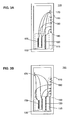
- Figure 3A is a cross-sectional view of the optical backplane of Figure 2.
- Figure 3B is a cross-sectional view showing an alternative embodiment of the optical backplane of Figure 2.
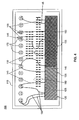
- Figure 4 is a schematic diagram illustrating another exemplary embodiment of the optical backplane disclosed herein.
- Figure 5 is a schematic diagram illustrating another exemplary embodiment of the optical backplane disclosed herein.
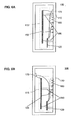
- Figure 6A is a cross-sectional view of the optical backplane of Figure 5.
- Figure 6B is a cross-sectional view showing an alternative embodiment of the optical backplane of Figure 5.
- the invention disclosed herein provides an improved optical backplane which incorporates a plurality of fiber-optic fabric inter-connectors (fabric inter-connectors) wherein each one can communicatively link selected optical backplane connectors.
- the invention provides for an optical backplane utilising several fabric inter-connectors having a high degree of manufacturability.
- the plurality of fabric inter-connectors can be configured to stack with one another and to at least partially overlap with one another.
- the fabric inter-connectors can be configured in accordance with the physical dimensions of the optical backplane as well as the physical location of the optical backplane connectors disposed therein.
- FIG. 1 is a schematic diagram illustrating an exemplary fabric inter-connector 120 which can be used within the optical backplane of the present invention.
- the fabric inter-connector 120 can include a body portion 125 and a plurality of legs 130 extending from the body portion. Each of the legs is terminated into an optical connector 132.
- the fabric inter-connector 120 can be substantially flat, it can be manufactured in any of a variety of shapes to accommodate various optical backplane configurations.
- the body portion 125, as well as each of the legs 130 can be configured with various lengths, widths, and shapes.
- fabric inter-connectors can be manufactured to connect particular predetermined optical backplane connectors within an optical backplane.
- Fabric inter-connectors as disclosed herein are commercially available from manufacturers such as U.S. Conec, Ltd., of Hickory, North Carolina.
- the legs 130 can include a service loop portion 185.
- the service loop portion 185 provides added length to the legs such that a poorly terminated connector 132 can be cut off and replaced with a new or different connector thereby eliminating the need to discard the entire fabric inter-connector.
- the service loop portion can be in the form of excess slack in a leg, or alternatively, can be an actual loop (not shown) in a leg. Regardless, the service loop portion 185 increases the manufacturability of the multi-fabric optical backplane design and facilitates service of the optical backplane.
- the fabric inter-connector 120 can include a plurality of legs 130 of various lengths. In one embodiment, the fabric inter-connector 120 can include at least three legs. Still, it should be appreciated that the fabric inter-connector 120 can be configured with any predetermined number of legs so as to communicatively link particular optical backplane connectors within an optical backplane.
- Each of the legs 130 includes an optical fiber bundle disposed therein. Although the legs can include any suitable number of optical fibers, in a preferred embodiment of the invention, the legs can include 12 optical fibers. Regardless, the optical fibers can be disposed within an adhesive layer which in turn can be located between two substrate layers of the fabric inter-connector.
- each leg can terminate into an optical connector 132.
- the optical connectors 132 can be complimentary to optical connectors supported within the optical backplane to be discussed herein. Accordingly, the optical connectors can cooperatively engage selected.optical backplane connectors.
- Optical connectors 132 can be any of a variety of suitable optical connectors.
- the optical connectors can be MT connectors as are well known in the art.
- an MT connector can accommodate legs of the fabric inter-connector having 4, 8, 12, or 24 optical fibers disposed therein.
- the fabric inter-connector 120 of Figure 1 has been incorporated into various embodiments of the present invention to be discussed herein. Accordingly, although further illustrations of the fabric inter-connectors differ from that of Figure 1, it should be appreciated that such differences are for purposes of illustration only. For example, nodes have been incorporated within the figures to better illustrate the relation between legs and corresponding body portions of the fabric inter-connectors.
- FIG 2 is a schematic diagram illustrating an exemplary embodiment of an optical backplane assembly 100 in accordance with the inventive arrangements disclosed herein.
- the optical backplane assembly 100 can include a structural frame 110 which can support a plurality of optical backplane connectors.
- the optical backplane connectors can be MT connectors 180 for cooperatively engaging MT connectors disposed on the legs of the fabric inter-connectors.
- the MT connectors can be configured within cylindrical connectors 170 or can be individually disposed within the structural frame 110.
- the optical backplane connectors 170 and 180 can be arranged in any of a variety of groupings.
- the cylindrical connectors 170 can be arranged in close proximity and substantially aligned with one another.
- the individual MT connectors 180 can be grouped closely and substantially aligned with one another. Still, the optical backplane connectors need not be disposed within the structural frame in any particular ordering or grouping. Moreover, it should be appreciated that the invention is not limited to the use of MT connectors only. Accordingly, any of a variety suitable fiber-optic connectors can be used within the optical backplane assembly 100.
- the optical backplane connectors 170 and 180 can be communicatively linked by one or more of the fabric inter-connectors 120 of Figure 1.
- the fabric inter-connectors 120 of Figure 1 two additional and similar fabric inter-connectors 135 and 155 are shown for purposes of illustration. Although several fabric inter-connectors are shown, in this case three, it should be appreciated that additional fabric inter-connectors can be incorporated as needed within the optical backplane assembly 100.
- the fabric inter-connectors can be substantially aligned and stacked within the structural frame 110 of the optical backplane assembly 100 so as not to substantially obstruct the optical backplane connectors 170 and/or 180.
- the fabric inter-connectors 120, 135, and 155 can include substantially flat body portions 125, 140, and 160 respectively.
- body portion 140 can be smaller in length and/or width than body portion 125 so as to fit within the perimeter of body portion 125.
- body portion 160 can be configured to fit within the perimeter of body portion 140.
- additional fabric inter-connectors can be included wherein each body portion can be configured to fit within, or at least not extend beyond, a perimeter of an adjacent body portion.
- the fabric inter-connector 120 can include a plurality of legs 130 extending outward from the body portion for engaging selected optical backplane connectors 170 and/or 180.
- each of fabric inter-connectors 135 and 155 can include a plurality of legs 145 and 165 extending outward from their respective body portions for communicatively linking selected optical backplane connectors 170 and/or 180.
- the legs 130, 145, and 165 can be configured to include a service loop portion 185 which facilitates the replacement of individual optical fiber connectors.
- the fabric inter-connectors 120, 135, and 155 can be configured according to the physical dimensions of the optical backplane assembly 100, and more particularly, for cooperatively stacking with one another within the structural frame 110.
- the structural frame 110 can include a containment structure 190 for securing the body portions of the fabric inter-connectors.
- the containment structure 190 can be a concave portion of the structural frame 110 or can be defined by a raised ridge surrounding or encompassing the body portions 125, 140, and 160 of the fabric inter-connectors 120, 135, and 155 respectively. Accordingly, the containment structure 190 can define a containment zone 115 within the structural frame 110 to be occupied exclusively by the body portions 125, 140, and 160.
- each of the fabric inter-connectors can be marked with a unique identifier.
- each fabric inter-connector can be marked or manufactured with a unique color throughout its body portion and leg portions.
- one fabric inter-connector can be easily identified and distinguished from another one of the fabric inter-connectors to facilitate replacement and/or service of the fabric inter-connector or the optical backplane in general.
- an alphanumeric identifier can be used to distinguish different fabric inter-connectors.
- a common alphanumeric identifier can be placed on different locations on, or throughout, each fabric inter-connector body portion and corresponding leg portions.
- the optical backplane assembly 100 can be configured such that one fabric inter-connector connects selected optical backplane connectors which are associated with particular related systems or components. That fabric inter-connector can be associated with a particular marker or color. Accordingly, each different grouping of related systems or components can be communicatively linked by a fabric inter-connector having a marker associated with that grouping of components.
- Figure 3A illustrates a cross-sectional view taken along line 3-3 in the embodiment of Figure 2.
- the optical backplane assembly 100 can include a structural frame 110 supporting a plurality of optical backplane connectors 170 and 180.
- the optical backplane connectors 170 and 180 can be arranged in any of a variety of groupings.
- the cylindrical connectors 170 can be arranged in close proximity and substantially aligned with one another.
- the individual MT connectors 180 can be grouped closely and substantially aligned with one another.
- the structural frame 110 includes the containment structure 190, which further defines the containment zone 115.
- the containment structure 190 is a concave portion of the structural frame 110.
- the body portions of the fabric inter-connectors 120, 135, and 155 can be positioned within the containment zone 115.
- the body portions, as well as the containment zone 115 can be positioned within the containment structure 190.
- Figure 3B is a cross-sectional view along line 3-3 of an alternative embodiment of the optical backplane of Figure 2 wherein the optical backplane connectors 170 and 180 have been disposed on opposing panels of the optical backplane assembly 100.
- the fabric inter-connectors 120, 135, and 155 have been positioned between the opposing panels of the structural frame 110.
- the containment structure 190 is formed by a raised ridge which can surround the body portions of the fabric inter-connectors. Similar to the embodiment of Figure 3A, the containment structure 190 can define the containment zone 115, which also can be positioned within the containment structure 190.
- Figure 4 is a schematic diagram illustrating another exemplary embodiment of the optical backplane assembly 100 wherein the fabric inter-connectors are substantially aligned and cooperatively stacked one on top of the other.
- each of the body portions 125, 140, and 160 of the fabric inter-connectors 120, 135, and 155 respectively can be stacked one on top of the other.
- Figure 4 depicts the body portions as having a common width dimension with varying lengths. Still, the body portions can be configured to have common lengths with varying widths or similar, if not identical, lengths and widths so as to more closely stack and align with one another. Thus, the body portions can be configured to share at least one common dimension.
- the body portions of the fabric inter-connectors can be substantially aligned and cooperatively stacked, particular body portions can extend beyond adjacent body portions, thereby leaving a tab portion exposed or uncovered by the adjacent body portions.
- a tab portion of body portion 140 is left exposed despite adjacent body portion 160 being located in front of body portion 140.
- body portion 140 extends beyond body portion 160 leaving exposed the tab portion of body portion 140.
- a tab portion of body portion 125 extends beyond and is left exposed by body portion 140.
- the fabric inter-connectors can be configured according to the particular physical dimensions of the optical backplane assembly 100 as well as the physical placement of the optical backplane connectors.
- Figure 5 is a schematic diagram illustrating another exemplary embodiment of the optical backplane disclosed herein.
- the fabric inter-connectors 120, 135, and 160 are at least partially stacked, however, the body portions 125, 140, and 160 need not be substantially aligned with one another.
- the body portions of the fabric inter-connectors can be configured with various shapes. Further, the body portions can be disposed throughout the structural frame 110. The shapes and locations of the body portions can be determined largely according to the physical location of the various optical backplane connectors 170 and 180 and the physical dimensions of the optical backplane assembly 100 itself.]
- Figure 6A is a cross-sectional view of the embodiment taken along line 6-6 of Figure 5.
- the cylindrical optical connectors 170 have been organized and substantially aligned within the structural frame 110.
- the individual connectors 180 also have been organized and substantially aligned within the structural frame 110.
- the fabric inter-connectors are preferably secured by at least one containment structure 190. Multiple containment structures 190 can be included as needed to support the necessary number of fabric inter-connectors incorporated into the optical backplane assembly 100.
- the containment structures 190 can be any of a variety of securing mechanisms for securing the fabric inter-connectors.
- the containment structures 190 can be shaped to cooperatively support or engage the fabric inter-connectors.
- the containment structures 190 can include a clip, a pin, an adhesive, hook and loop fasteners, combinations thereof, and the like.
- the body portions can be located within a containment zone 115 as previously discussed. Still, it should be appreciated that both types of containment structures, for example clips as well as a concave portion of the structural frame 110, can be used to position the body portions of the fabric inter-connectors within the containment zone.
- Figure 6B is a cross-sectional view of an alternative embodiment of the optical backplane of Figure 5 wherein the optical backplane connectors are disposed within the structural frame with a different ordering. Accordingly, Figure 6B illustrates an exemplary embodiment wherein the optical backplane connectors 170 and 180 have been disposed on opposing panels of the optical backplane assembly 100. Similar to the embodiment of Figure 6A, the fabric inter-connectors can be secured within a containment zone 115 by one or more containment structures 190.
- the present invention addresses the deficiencies of the prior art by providing a highly serviceable and cost effective optical backplane having a high degree of manufacturability. Importantly, the present invention addresses these issues while adhering to the strict size limitations often imposed upon optical backplanes. Still, the invention disclosed herein can be embodied in other specific forms without departing from the spirit or essential attributes thereof. Accordingly, reference should be made to the following claims, rather than to the foregoing specification, as indicating the scope of the invention.
Landscapes
- Physics & Mathematics (AREA)
- General Physics & Mathematics (AREA)
- Optics & Photonics (AREA)
- Light Guides In General And Applications Therefor (AREA)
- Mechanical Coupling Of Light Guides (AREA)
- Optical Couplings Of Light Guides (AREA)
Abstract
Description
The present invention addresses the deficiencies of the prior art by providing a highly serviceable and cost effective optical backplane having a high degree of manufacturability. Importantly, the present invention addresses these issues
while adhering to the strict size limitations often imposed upon optical backplanes. Still, the invention disclosed herein can be embodied in other specific forms without departing from the spirit or essential attributes thereof. Accordingly, reference should be made to the following claims, rather than to the
foregoing specification, as indicating the scope of the invention.
Claims (26)
- An optical backplane assembly comprising:a structural member for supporting a plurality of optical backplane connectors; and,a plurality of fiber-optic fabric inter-connectors, each one of said plurality of fiber-optic fabric inter-connectors comprising a substantially flat body portion and having at least three legs extending outward from said body portion, each said leg having at least one optical fiber disposed therein and an optical fiber connector for cooperatively engaging selected ones of said plurality of optical backplane connectors, said body portions of said plurality of fiber-optic fabric inter-connectors being stacked so as to at least partially overlap one another.
- The optical backplane assembly of claim 1, wherein all said legs have a service loop portion whereby a defective one of said optical fiber connectors can be removed and replaced on any said leg without replacing said fiber-optic fabric inter-connector.
- The optical backplane assembly of claim 1 or 2, wherein each of said fiber-optic fabric inter-connectors is marked with a unique visual identifier.
- The optical backplane assembly of claim 3, wherein said unique visual identifier appears throughout said body portion and said legs.
- The optical backplane assembly of claim 3 or 4, wherein said unique visual identifier is a color.
- The optical backplane assembly of one of the claims 1 to 5, wherein each of said body portions shares a common co-equal dimension.
- The optical backplane assembly of one of the claim 1 to 6, wherein said legs are selectively configured to have at least a minimum length so as to accommodate a predetermined minimum bend radius for said at least one optical fiber disposed therein.
- The optical backplane assembly of one of the claims 1 to 7, further comprising:at least one containment structure for securing at least one of said body portions of said plurality of fiber-optic fabric inter-connectors within a containment zone.
- The optical backplane assembly of claim 8, wherein said containment zone is exclusive of said optical backplane connectors, whereby said body portions do not substantially obstruct said plurality of optical backplane connectors.
- The optical backplane assembly of one of the claims 1 to 9, wherein said body portion of each one of said plurality of fiber-optic fabric inter-connectors is configured with a predetermined shape based upon the physical dimensions of said optical backplane assembly and the physical placement of said optical backplane connectors disposed therein, and wherein said predetermined shapes are configured for cooperatively stacking with one another.
- The optical backplane assembly of claim 10, wherein said predetermined shape of each said body portion is selectively configured not to extend beyond a perimeter of an adjacent one of said body portions.
- The optical backplane assembly of claim 10 or 11, wherein each said body portion is selectively configured to fit within a perimeter of an adjacent one of said body portions so as to leave exposed at least a tab portion of said adjacent body portion.
- An optical backplane assembly comprising:a structural member for supporting a plurality of optical backplane connectors;a plurality of fiber-optic fabric inter-connectors, each one of said plurality of fiber-optic fabric inter-connectors comprising a substantially flat body portion and having a plurality of legs extending outward from said body portion, each said leg having at least one optical fiber disposed therein and an optical fiber connector for cooperatively engaging selected ones of said plurality of optical backplane connectors; and,at least one containment structure for securing at least one of said body portions of said plurality of fiber-optic fabric inter-connectors within a containment zone.
- The optical backplane assembly of claim 13, wherein said containment zone is exclusive of said optical backplane connectors, whereby said body portions do not substantially obstruct said plurality of optical backplane connectors.
- A method of configuring an optical backplane assembly comprising:forming a structural member for supporting a plurality of optical backplane connectors;forming a plurality of fiber-optic fabric inter-connectors, each one of said plurality of fiber-optic fabric inter-connectors comprising a substantially flat body portion having at least three legs extending outward from said body portion, each said leg having at least one optical fiber disposed therein and an optical connector for cooperatively engaging selected ones of said plurality of optical backplane connectors;arranging said plurality of fiber-optic fabric inter-connectors such that said body portions of said plurality of fiber-optic fabric inter-connectors are stacked so as to at least partially overlap with one another; and,communicatively linking selected ones of said plurality of optical backplane connectors with particular ones of said plurality of fiber-optic fabric inter-connectors.
- The method of claim 15, wherein said forming a plurality of fiber-optic fabric inter-connectors step further comprises forming a service loop portion for all of said legs, whereby a defective one of said optical fiber connectors can be removed and replaced on any said leg without replacing said fiber-optic fabric inter-connector.
- The method of claim 15 or 16, further comprising:marking each of said fiber-optic fabric inter-connectors with a unique visual identifier.
- The method of claim 17, wherein said marking step further comprises applying said unique visual identifier throughout said body portion and said legs.
- The method of claim 17 or 18, wherein said marking step further comprises applying a distinct color to each of said fiber-optic fabric inter-connectors.
- The method of one of the claims 16 to 19, wherein said forming a plurality of fiber-optic fabric inter-connectors step further comprises forming each of said body portions to have a common co-equal dimension.
- The method of one of the claims 16 to 20, wherein said forming a plurality of fiber-optic fabric inter-connectors step further comprises forming said legs to have at least a minimum length so as to accommodate a predetermined minimum bend radius for said at least one optical fiber disposed therein.
- The method of one of the claims 16 to 21, further comprising:forming at least one containment structure for securing at least one of said body portions of said plurality of fiber-optic fabric inter-connectors within a containment zone.
- The method of claim 22, wherein said forming at least one containment structure step further comprises defining said containment zone to be exclusive of said optical backplane connectors, whereby said body portions do not substantially obstruct said plurality of optical backplane connectors.
- The method of one of the claims 16 to 23, wherein said forming a plurality of fiber-optic fabric inter-connectors step further comprises shaping each one of said plurality of fiber-optic fabric inter-connectors according to a predetermined shape based upon the physical dimensions of said optical backplane assembly and the physical placement of said optical backplane connectors disposed therein, said predetermined shapes being configured for cooperatively stacking with one another.
- The method of claim 24, wherein said shaping step further comprises selectively shaping each said body portion not to extend beyond a perimeter of an adjacent one of said body portions.
- The method of claim 24 or 25, wherein said shaping step further comprises selectively shaping each said body portion to fit within a perimeter of an adjacent one of said body portions so as to leave exposed at least a tab portion of said adjacent body portion.
Applications Claiming Priority (2)
| Application Number | Priority Date | Filing Date | Title |
|---|---|---|---|
| US5042 | 2001-12-04 | ||
| US10/005,042 US6587631B2 (en) | 2001-12-04 | 2001-12-04 | Fiber-optic backplane method and apparatus |
Publications (3)
| Publication Number | Publication Date |
|---|---|
| EP1318422A2 true EP1318422A2 (en) | 2003-06-11 |
| EP1318422A3 EP1318422A3 (en) | 2004-06-16 |
| EP1318422B1 EP1318422B1 (en) | 2007-10-17 |
Family
ID=21713841
Family Applications (1)
| Application Number | Title | Priority Date | Filing Date |
|---|---|---|---|
| EP02026958A Expired - Lifetime EP1318422B1 (en) | 2001-12-04 | 2002-12-04 | Fiber-optic connector for backplane |
Country Status (5)
| Country | Link |
|---|---|
| US (1) | US6587631B2 (en) |
| EP (1) | EP1318422B1 (en) |
| JP (1) | JP3920202B2 (en) |
| CA (1) | CA2413227C (en) |
| DE (1) | DE60222984T2 (en) |
Families Citing this family (4)
| Publication number | Priority date | Publication date | Assignee | Title |
|---|---|---|---|---|
| US6533463B2 (en) * | 2001-07-31 | 2003-03-18 | Pluris, Inc. | Adjustable and modular backplane assembly for providing a fiber-optics communication backplane |
| US7058274B2 (en) * | 2003-03-11 | 2006-06-06 | Pluris, Inc. | Adjustable and modular backplane assembly for providing a fiber-optics communication backplane |
| KR100871252B1 (en) * | 2007-01-19 | 2008-11-28 | 삼성전자주식회사 | Flexible printed circuit board with optical / electrical wiring using optical fiber |
| US8517615B1 (en) * | 2012-03-28 | 2013-08-27 | Netgami System L.L.C. | Multi-diameter optical fiber link for all optics system backplane solution |
Family Cites Families (8)
| Publication number | Priority date | Publication date | Assignee | Title |
|---|---|---|---|---|
| US5125056A (en) * | 1986-05-14 | 1992-06-23 | Mcdonnell Douglas Corporation | Fiber optic connector assembly |
| US5268986A (en) * | 1991-09-09 | 1993-12-07 | Sumitomo Electric Industries, Ltd. | Redundant length treatment mechanism for optical fiber at terminal of optical cable |
| US5204925A (en) * | 1991-09-11 | 1993-04-20 | At&T Bell Laboratories | Optical interconnection of circuit packs |
| GB2314214B (en) | 1996-06-13 | 2000-09-20 | Marconi Gec Ltd | Optical backplane |
| US5902435A (en) * | 1996-12-31 | 1999-05-11 | Minnesota Mining And Manufacturing Company | Flexible optical circuit appliques |
| US5980312A (en) | 1998-01-12 | 1999-11-09 | Amphenol Corporation | Modular optical/electronic backplane assembly |
| US6445866B1 (en) * | 1999-11-29 | 2002-09-03 | Molex Incorporated | Optical interconnection apparatus and method of fabricating same |
| JP2001330738A (en) * | 2000-05-19 | 2001-11-30 | Sumitomo Electric Ind Ltd | Optical fiber sheet |
-
2001
- 2001-12-04 US US10/005,042 patent/US6587631B2/en not_active Expired - Fee Related
-
2002
- 2002-11-29 JP JP2002348364A patent/JP3920202B2/en not_active Expired - Fee Related
- 2002-11-29 CA CA002413227A patent/CA2413227C/en not_active Expired - Fee Related
- 2002-12-04 EP EP02026958A patent/EP1318422B1/en not_active Expired - Lifetime
- 2002-12-04 DE DE60222984T patent/DE60222984T2/en not_active Expired - Fee Related
Also Published As
| Publication number | Publication date |
|---|---|
| EP1318422A3 (en) | 2004-06-16 |
| CA2413227A1 (en) | 2003-06-04 |
| US20030103752A1 (en) | 2003-06-05 |
| JP2003172826A (en) | 2003-06-20 |
| EP1318422B1 (en) | 2007-10-17 |
| DE60222984T2 (en) | 2008-02-07 |
| JP3920202B2 (en) | 2007-05-30 |
| US6587631B2 (en) | 2003-07-01 |
| CA2413227C (en) | 2008-02-26 |
| DE60222984D1 (en) | 2007-11-29 |
Similar Documents
| Publication | Publication Date | Title |
|---|---|---|
| US9684134B2 (en) | Managed fiber connectivity systems | |
| AU700072B2 (en) | Smart skin array woven fiber optic ribbon and arrays and packaging thereof | |
| CN101151912A (en) | Cable management components, systems and methods | |
| EP1962121A1 (en) | Method and apparatus of cross-connecting optical fibers | |
| US20040136638A1 (en) | Layered optical circuit | |
| US6587631B2 (en) | Fiber-optic backplane method and apparatus | |
| US6775458B2 (en) | Fixture for a flexible shuffle circuit | |
| CN215184590U (en) | Wiring panel | |
| EP1595174B1 (en) | Method for cross connecting optical fibers | |
| KR101548705B1 (en) | integrated optical splitter | |
| JP2023083096A (en) | optical communication system | |
| JP3747596B2 (en) | Connector partition plate | |
| CN216673402U (en) | Circuit board that soft or hard combines | |
| JP2503622B2 (en) | Optical star coupler device | |
| JP3853599B2 (en) | Manufacturing method of optical fiber sheet with optical connector | |
| JPH08227027A (en) | Optical connector unit | |
| KR19990037858A (en) | A supporting screen for a crop and the method of producing the same | |
| JP2001051154A (en) | Ferrule for optical fiber |
Legal Events
| Date | Code | Title | Description |
|---|---|---|---|
| PUAI | Public reference made under article 153(3) epc to a published international application that has entered the european phase |
Free format text: ORIGINAL CODE: 0009012 |
|
| AK | Designated contracting states |
Designated state(s): AT BE BG CH CY CZ DE DK EE ES FI FR GB GR IE IT LI LU MC NL PT SE SI SK TR |
|
| AX | Request for extension of the european patent |
Extension state: AL LT LV MK RO |
|
| PUAL | Search report despatched |
Free format text: ORIGINAL CODE: 0009013 |
|
| AK | Designated contracting states |
Kind code of ref document: A3 Designated state(s): AT BE BG CH CY CZ DE DK EE ES FI FR GB GR IE IT LI LU MC NL PT SE SI SK TR |
|
| AX | Request for extension of the european patent |
Extension state: AL LT LV MK RO |
|
| RIC1 | Information provided on ipc code assigned before grant |
Ipc: 7G 02B 6/43 A |
|
| 17P | Request for examination filed |
Effective date: 20041102 |
|
| AKX | Designation fees paid |
Designated state(s): DE FR GB IT |
|
| 17Q | First examination report despatched |
Effective date: 20050311 |
|
| GRAP | Despatch of communication of intention to grant a patent |
Free format text: ORIGINAL CODE: EPIDOSNIGR1 |
|
| GRAS | Grant fee paid |
Free format text: ORIGINAL CODE: EPIDOSNIGR3 |
|
| GRAA | (expected) grant |
Free format text: ORIGINAL CODE: 0009210 |
|
| AK | Designated contracting states |
Kind code of ref document: B1 Designated state(s): DE FR GB IT |
|
| REG | Reference to a national code |
Ref country code: GB Ref legal event code: FG4D |
|
| REF | Corresponds to: |
Ref document number: 60222984 Country of ref document: DE Date of ref document: 20071129 Kind code of ref document: P |
|
| PGFP | Annual fee paid to national office [announced via postgrant information from national office to epo] |
Ref country code: IT Payment date: 20071222 Year of fee payment: 6 |
|
| PGFP | Annual fee paid to national office [announced via postgrant information from national office to epo] |
Ref country code: GB Payment date: 20071227 Year of fee payment: 6 |
|
| ET | Fr: translation filed | ||
| PGFP | Annual fee paid to national office [announced via postgrant information from national office to epo] |
Ref country code: DE Payment date: 20080131 Year of fee payment: 6 |
|
| PGFP | Annual fee paid to national office [announced via postgrant information from national office to epo] |
Ref country code: FR Payment date: 20071217 Year of fee payment: 6 |
|
| PLBE | No opposition filed within time limit |
Free format text: ORIGINAL CODE: 0009261 |
|
| STAA | Information on the status of an ep patent application or granted ep patent |
Free format text: STATUS: NO OPPOSITION FILED WITHIN TIME LIMIT |
|
| 26N | No opposition filed |
Effective date: 20080718 |
|
| GBPC | Gb: european patent ceased through non-payment of renewal fee |
Effective date: 20081204 |
|
| REG | Reference to a national code |
Ref country code: FR Ref legal event code: ST Effective date: 20090831 |
|
| PG25 | Lapsed in a contracting state [announced via postgrant information from national office to epo] |
Ref country code: DE Free format text: LAPSE BECAUSE OF NON-PAYMENT OF DUE FEES Effective date: 20090701 |
|
| PG25 | Lapsed in a contracting state [announced via postgrant information from national office to epo] |
Ref country code: GB Free format text: LAPSE BECAUSE OF NON-PAYMENT OF DUE FEES Effective date: 20081204 |
|
| PG25 | Lapsed in a contracting state [announced via postgrant information from national office to epo] |
Ref country code: FR Free format text: LAPSE BECAUSE OF NON-PAYMENT OF DUE FEES Effective date: 20081231 |
|
| PG25 | Lapsed in a contracting state [announced via postgrant information from national office to epo] |
Ref country code: IT Free format text: LAPSE BECAUSE OF NON-PAYMENT OF DUE FEES Effective date: 20081204 |