EP1318292A2 - Method of manufacturing a fuel rail - Google Patents
Method of manufacturing a fuel rail Download PDFInfo
- Publication number
- EP1318292A2 EP1318292A2 EP02257441A EP02257441A EP1318292A2 EP 1318292 A2 EP1318292 A2 EP 1318292A2 EP 02257441 A EP02257441 A EP 02257441A EP 02257441 A EP02257441 A EP 02257441A EP 1318292 A2 EP1318292 A2 EP 1318292A2
- Authority
- EP
- European Patent Office
- Prior art keywords
- tube
- blocks
- fuel
- seal
- providing
- Prior art date
- Legal status (The legal status is an assumption and is not a legal conclusion. Google has not performed a legal analysis and makes no representation as to the accuracy of the status listed.)
- Granted
Links
Images

Classifications
-
- B—PERFORMING OPERATIONS; TRANSPORTING
- B21—MECHANICAL METAL-WORKING WITHOUT ESSENTIALLY REMOVING MATERIAL; PUNCHING METAL
- B21D—WORKING OR PROCESSING OF SHEET METAL OR METAL TUBES, RODS OR PROFILES WITHOUT ESSENTIALLY REMOVING MATERIAL; PUNCHING METAL
- B21D39/00—Application of procedures in order to connect objects or parts, e.g. coating with sheet metal otherwise than by plating; Tube expanders
- B21D39/06—Application of procedures in order to connect objects or parts, e.g. coating with sheet metal otherwise than by plating; Tube expanders of tubes in openings, e.g. rolling-in
-
- B—PERFORMING OPERATIONS; TRANSPORTING
- B21—MECHANICAL METAL-WORKING WITHOUT ESSENTIALLY REMOVING MATERIAL; PUNCHING METAL
- B21D—WORKING OR PROCESSING OF SHEET METAL OR METAL TUBES, RODS OR PROFILES WITHOUT ESSENTIALLY REMOVING MATERIAL; PUNCHING METAL
- B21D26/00—Shaping without cutting otherwise than using rigid devices or tools or yieldable or resilient pads, i.e. applying fluid pressure or magnetic forces
- B21D26/02—Shaping without cutting otherwise than using rigid devices or tools or yieldable or resilient pads, i.e. applying fluid pressure or magnetic forces by applying fluid pressure
- B21D26/033—Deforming tubular bodies
- B21D26/035—Deforming tubular bodies including an additional treatment performed by fluid pressure, e.g. perforating
-
- B—PERFORMING OPERATIONS; TRANSPORTING
- B21—MECHANICAL METAL-WORKING WITHOUT ESSENTIALLY REMOVING MATERIAL; PUNCHING METAL
- B21D—WORKING OR PROCESSING OF SHEET METAL OR METAL TUBES, RODS OR PROFILES WITHOUT ESSENTIALLY REMOVING MATERIAL; PUNCHING METAL
- B21D53/00—Making other particular articles
- B21D53/84—Making other particular articles other parts for engines, e.g. connecting-rods
-
- F—MECHANICAL ENGINEERING; LIGHTING; HEATING; WEAPONS; BLASTING
- F02—COMBUSTION ENGINES; HOT-GAS OR COMBUSTION-PRODUCT ENGINE PLANTS
- F02M—SUPPLYING COMBUSTION ENGINES IN GENERAL WITH COMBUSTIBLE MIXTURES OR CONSTITUENTS THEREOF
- F02M55/00—Fuel-injection apparatus characterised by their fuel conduits or their venting means; Arrangements of conduits between fuel tank and pump F02M37/00
- F02M55/02—Conduits between injection pumps and injectors, e.g. conduits between pump and common-rail or conduits between common-rail and injectors
- F02M55/025—Common rails
-
- Y—GENERAL TAGGING OF NEW TECHNOLOGICAL DEVELOPMENTS; GENERAL TAGGING OF CROSS-SECTIONAL TECHNOLOGIES SPANNING OVER SEVERAL SECTIONS OF THE IPC; TECHNICAL SUBJECTS COVERED BY FORMER USPC CROSS-REFERENCE ART COLLECTIONS [XRACs] AND DIGESTS
- Y10—TECHNICAL SUBJECTS COVERED BY FORMER USPC
- Y10T—TECHNICAL SUBJECTS COVERED BY FORMER US CLASSIFICATION
- Y10T29/00—Metal working
- Y10T29/49—Method of mechanical manufacture
- Y10T29/49229—Prime mover or fluid pump making
-
- Y—GENERAL TAGGING OF NEW TECHNOLOGICAL DEVELOPMENTS; GENERAL TAGGING OF CROSS-SECTIONAL TECHNOLOGIES SPANNING OVER SEVERAL SECTIONS OF THE IPC; TECHNICAL SUBJECTS COVERED BY FORMER USPC CROSS-REFERENCE ART COLLECTIONS [XRACs] AND DIGESTS
- Y10—TECHNICAL SUBJECTS COVERED BY FORMER USPC
- Y10T—TECHNICAL SUBJECTS COVERED BY FORMER US CLASSIFICATION
- Y10T29/00—Metal working
- Y10T29/49—Method of mechanical manufacture
- Y10T29/49805—Shaping by direct application of fluent pressure
-
- Y—GENERAL TAGGING OF NEW TECHNOLOGICAL DEVELOPMENTS; GENERAL TAGGING OF CROSS-SECTIONAL TECHNOLOGIES SPANNING OVER SEVERAL SECTIONS OF THE IPC; TECHNICAL SUBJECTS COVERED BY FORMER USPC CROSS-REFERENCE ART COLLECTIONS [XRACs] AND DIGESTS
- Y10—TECHNICAL SUBJECTS COVERED BY FORMER USPC
- Y10T—TECHNICAL SUBJECTS COVERED BY FORMER US CLASSIFICATION
- Y10T29/00—Metal working
- Y10T29/49—Method of mechanical manufacture
- Y10T29/49826—Assembling or joining
- Y10T29/49908—Joining by deforming
- Y10T29/49938—Radially expanding part in cavity, aperture, or hollow body
- Y10T29/4994—Radially expanding internal tube
Definitions
- the present invention relates to the forming of fuel rails, and more particularly to forming fuel rails employing a hydroforming process.
- a typical high pressure fuel rail includes a hollow conduit having a plurality of U-shaped blocks provided thereon. Each of the blocks has a recessed fuel injector port formed therein to receive a portion of a fuel injector, and also typically includes a mounting member so that the block functions as a mounting bracket as well.
- These fuel rail assemblies have commonly been manufactured by forming a plurality of fuel holes in the conduit, then brazing or otherwise securing each of the blocks about a respective one of the holes.
- This invention relates to an improved method for manufacturing a fuel rail assembly for use with internal combustion engines employing fuel injectors.
- the invention relates to an improved high pressure fuel rail assembly for use with direct injection engines.
- the present invention contemplates a method of manufacturing a fuel rail assembly comprising the steps of: providing a hollow tube and a plurality of blocks, wherein each of the blocks has a passage formed therethrough and a recessed fuel injector port; inserting the tube into the passages in the blocks; mounting the tube and blocks in a hydroforming die, and positioning the blocks in desired positions relative to the tube; supplying pressurized fluid to the interior of the tube, causing the tube to expand outwardly into engagement with the blocks; and piercing holes through the tube within each of the blocks to provide fluid communication with the associated recessed fuel injector ports.
- the present invention further contemplates a method of manufacturing a fuel rail assembly comprising the steps of: providing a hollow tube and a plurality of blocks, wherein each of the blocks has a passage formed therethrough and a recessed fuel injector port; providing at least one seal; inserting the tube into the passages in the blocks; locating the seal between the tube and at least one of the passages; mounting the tube and blocks in a hydroforming die, and positioning the blocks in desired positions relative to the tube; and supplying pressurized fluid to the interior of the tube, causing the tube to expand outwardly into engagement with the seal and the blocks.
- the present invention also contemplates a fuel injector assembly formed by one of the above noted methods.
- an object of the present invention is to form an improved fuel rail assembly employing a hydroforming process.
- An advantage of the present invention is that the fuel rail assembly can be formed more efficiently.
- Another advantage of the present invention is that the fuel rail assembly formed is less likely to be warped or have potential fuel leak paths.
- Figs. 1-3 illustrate a fuel rail assembly 20 for a typical high pressure fuel, direct injected engine (not shown).
- the fuel rail assembly 20 includes a main fuel tube 22, with three spaced fuel injector/mounting blocks 24 and one end feed block 26 mounted thereon.
- Each block 24, 26 includes a fuel tube passage 36 for receiving the outer surface 38 of the fuel tube 22 therethrough.
- the injector/mounting blocks 24 also include cavities that form fuel injector ports 28, which are shaped to receive high pressure fuel injectors (not shown).
- the three fuel injector/mounting blocks 24 each include a mounting bore 30 extending through the blocks 24 for receiving mounting bolts 32, that mount to the engine. Thus, these blocks 24 act as both supports for the fuel injectors themselves, and also the mechanism for mounting the fuel rail assembly 20 to the engine.
- the feed block 26 includes a cavity 29 that forms a cross feed port for a cross feed tube (not shown).
- the finished tube 20 includes four hydropierced holes 34, one at each of the three blocks 24 aligning with its respective injector port 28, and one at the block 26 to communicate with the cross feed port 29. Since these holes 34 are formed during the hydroforming process itself (as discussed below), they needn't be in the fuel tube 22 prior to the hydroforming process.
- the blocks 24, 26 are fabricated so that each of the passages 36 has a diameter approximately 0.01 to 0.02 inches (0.25 to 0.5 mm) larger than the initial diameter of the outside surface 38 of the fuel tube 22. This initial difference in diameters may vary depending upon the size and thickness of the components, and what type of seal is used, if any, as is desired for the particular fuel rail assembly being formed.
- seals 40 between the fuel tube outer surface 38 and the fuel tube passages 36. These seals 40 are desired because the fuel rail assembly 20 must retain, without leakage, high pressure fuel as it flows to the engine, under various environmental conditions. The advantage of having these seals 40, then, is to improve the sealing properties by reducing the chances for a leak path between the tube outside surface 38 and the passage 36.
- the relative thickness of the seals 40 are shown exaggerated for clarity in describing the invention.
- the actual thickness of the seals depends upon the particular type of seal used, among other factors, as is discussed below, but is generally on the order of 0.2 mm or less.
- the seals 40 can be an adhesive, a sealant, and/or metal, rubber or plastic. If the seal 40 is made of a sealant, then the preferred method is to pre-coat the fuel tube outer surface 38 at least at the locations where the tube holes 34 will be formed prior to installing the blocks 24, 26.
- the preferred sealant is a pre-applied sealant, which is an application where a liquid medium suspends tiny capsules of sealant. This pre-applied sealant is applied to the fuel tube surface 38 at the appropriate locations and allowed to dry. Then, during the hydroforming process, the high pressure will cause the capsules to rupture, and the sealant will flow and bond to the surfaces.
- the seal 40 is made of an adhesive, then it is preferred to pre-coat the tube outer surface 38 at the hole 34 locations with a pre-applied adhesive.
- These adhesives contain tiny capsules of resin and capsules of hardener that are suspended in a liquid medium. The liquid medium is applied to the tube surface 38, where a hole 38 will be formed, and is allowed to dry. During the hydroforming process, the high pressure between the tube outer surface 38 and the fuel tube passages 36 will cause the capsules containing the resin and the capsules containing the hardener to rupture, allowing the hardener & resin to mix, thus forming a tight adhesive seal.
- each seal 40 can include a small strip or coating of material sandwiched between each fuel tube passage 36 and the corresponding portion of the tube outer surface 38.
- the sealant or adhesive may be placed on either or both sides of the material, as is desired for the particular application.
- This material can be a flexible rubber or plastic. It can also be a ductile metal, such as copper. This ductile metal can be coated on the surface of the fuel tube using conventional processes for coating of metals on objects, such as plating or flashing, and can be applied locally, or along the whole tube.
- the soft metal can take the form of very thin, for example 0.005 inches (0.13 mm) thick, tubular sleeves, each slid between the fuel tube outer surface 38 and a corresponding fuel tube passage 36.
- the ductile metal can also be a very thin strip of shim stock, that is wrapped around the fuel tube 22, with a slight overlapping of the ends of the shim to assure a complete seal.
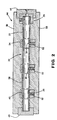
- Fig. 2 schematically illustrates the fuel rail assembly 20 after forming, but while still mounted in a hydroforming die assembly 44.
- This assembly 44 can include a first end die 46 for sealing one end of the tube 22, and a second end die 48 for sealing the other end of the tube 22 and providing a conduit for feeding the high pressure fluid into the tube 22 during the hydroforming process.
- This assembly 44 can also include two side dies 50 for surrounding and controlling the expansion of the tube 22.
- the two side dies 50 each include piercing pins 52, which translate radially inward on hydraulic pistons (not shown), for creating the hydropierced holes in the fuel tube 22 during the hydroforming process.
- the particular number and configuration of hydroforming dies can vary as is desired, and so the die assembly 44 shown is for illustrative purposes only.
- the hydroforming process for the fuel rail assembly 20 will now be described.
- the seals 40 are mounted or formed on the tube outer surface 38.
- Each of the blocks 24, 26 is then loaded on the fuel tube 22.
- the assembly 20 is placed in the hydroforming die assembly 44, with each of the parts at the desired location and orientation, and the die assembly is closed.
- the hydroforming now takes place.
- Pressurized fluid such as water
- a conventional end feed cylinder (not shown) sealingly engages the second end die 48 in a well known manner.
- the pressure of the fluid within the tube 22 is increased in a well known manner to such a magnitude that the fuel tube 22 is expanded outwardly into conformance with the die cavity defined by the die assembly 44 and against the fuel tube passages 36, swaging the blocks 24, 26 in place.
- the fuel tube 22 is deformed into the desired final shape.
- the amount of tube expansion illustrated in Fig. 2 is shown exaggerated for visualization purposes.
- the pressure will rupture the capsules. If a ductile metal is used for the seal 40, then the pressure will deform the metal, forming a tight seal.
- the holes 34 are pierced through the seals 40 and tube 22, within each of the blocks 24, 26, to provide fluid communication with the associated recessed fuel injector ports 28 and cross feed tube 29.
- the fuel rail assembly may then be removed from the hydroforming dies, and the part is essentially complete, except for some conventional post processing, such as plugging an open end of the fuel rail with an end cap (not shown) in a conventional manner.
- this embodiment shows three fuel injector blocks 24, which can be used, for example, as one side of a fuel rail assembly in a V-6 engine
- fuel rails with other numbers of fuel injectors are also within the scope of the present invention.
- the fuel rail assembly of the particular embodiment includes three main blocks and one end block, although various numbers of blocks may be employed depending upon the engine and fuel injector configuration.
- the blocks 24 include both a fuel injector port and a mounting bore, one can employ two sets of separate blocks, with one set having fuel injector ports and the other including the mounting bores, if so desired.
- the preferred embodiment describes a high pressure fuel rail for a direct injection engine, the present invention is also applicable to fuel rails for conventional fuel injected engines.
Landscapes
- Engineering & Computer Science (AREA)
- Mechanical Engineering (AREA)
- Chemical & Material Sciences (AREA)
- Combustion & Propulsion (AREA)
- General Engineering & Computer Science (AREA)
- Physics & Mathematics (AREA)
- Fluid Mechanics (AREA)
- Fuel-Injection Apparatus (AREA)
- Feeding And Controlling Fuel (AREA)
- Shaping Metal By Deep-Drawing, Or The Like (AREA)
Abstract
Description
Claims (10)
- A method of manufacturing a fuel rail assembly comprising the steps of:providing a hollow tube and a plurality of blocks, wherein each of the blocks has a passage formed therethrough and a recessed fuel injector port;inserting the tube into the passages in the blocks;mounting the tube and blocks in a hydroforming die, and positioning the blocks in desired positions relative to the tube;supplying pressurized fluid to the interior of the tube, causing the tube to expand outwardly into engagement with the blocks; andpiercing holes through the tube within each of the blocks to provide fluid communication with the associated recessed fuel injector ports.
- A fuel rail assembly formed in accordance with the method of claim 1.
- The method of claim 1 further including the steps of providing a seal; and locating the seal between the tube and at least one of the passages prior to the step of supplying pressurized fluid.
- A fuel rail assembly formed in accordance with the method of claim 3.
- The method of claim 3 wherein the step of providing a seal includes providing a seal formed by a sealant.
- The method of claim 5 wherein the step of providing a seal further includes providing a metallic layer in contact with the sealant.
- The method of claim 3 wherein the step of providing a seal includes providing a seal formed by an adhesive.
- The method of claim 7 wherein the step of providing a seal further includes providing a metallic layer in contact with the adhesive.
- The method of claim 3 wherein the step of providing a seal includes providing a seal made of rubber.
- The method of claim 3 wherein the step of providing a seal includes providing a seal made of plastic.
Applications Claiming Priority (2)
| Application Number | Priority Date | Filing Date | Title |
|---|---|---|---|
| US10/012,840 US6651327B1 (en) | 2001-12-10 | 2001-12-10 | Method of making hydroformed fuel rails |
| US12840 | 2001-12-10 |
Publications (3)
| Publication Number | Publication Date |
|---|---|
| EP1318292A2 true EP1318292A2 (en) | 2003-06-11 |
| EP1318292A3 EP1318292A3 (en) | 2004-06-16 |
| EP1318292B1 EP1318292B1 (en) | 2006-09-13 |
Family
ID=21756965
Family Applications (1)
| Application Number | Title | Priority Date | Filing Date |
|---|---|---|---|
| EP02257441A Expired - Lifetime EP1318292B1 (en) | 2001-12-10 | 2002-10-25 | Method of manufacturing a fuel rail |
Country Status (5)
| Country | Link |
|---|---|
| US (1) | US6651327B1 (en) |
| EP (1) | EP1318292B1 (en) |
| AT (1) | ATE339611T1 (en) |
| DE (1) | DE60214651T2 (en) |
| MX (1) | MXPA02012196A (en) |
Cited By (9)
| Publication number | Priority date | Publication date | Assignee | Title |
|---|---|---|---|---|
| WO2005053872A1 (en) * | 2003-12-04 | 2005-06-16 | Daimlerchrysler Ag | Method for joining joint parts to hollow profiles |
| EP1555426A1 (en) * | 2004-01-15 | 2005-07-20 | Siemens Aktiengesellschaft | Fuel-rail and method for manufacturing a fuel-rail |
| EP1524428A3 (en) * | 2003-10-15 | 2005-08-10 | Robert Bosch Gmbh | Method of manufacturing an accumulator having plane mounting surfaces |
| EP1482169A3 (en) * | 2003-05-29 | 2006-06-07 | Delphi Technologies, Inc. | Injector clamp and assembly |
| EP1760306A1 (en) * | 2005-09-06 | 2007-03-07 | Siemens Aktiengesellschaft | Housing |
| FR2916833A1 (en) * | 2007-05-29 | 2008-12-05 | Snecma Sa | Annular shaped fuel supplying ramp for e.g. turbo-prop of aircraft, has bosses formed by hydroforming and inclined with respect to axis of curved pipe, where bosses are cut at their top for forming orifices for passage of fuel |
| CN105508105A (en) * | 2014-09-25 | 2016-04-20 | 联合汽车电子有限公司 | End cover of plastic roil rail, oil rail body and welding method for end cover and oil rail body |
| CN109865992A (en) * | 2018-12-11 | 2019-06-11 | 上海威克迈龙川汽车发动机零件有限公司 | The processing technology of distribution pipe and engine high pressure oil rail assembly comprising the distribution pipe |
| CN110479791A (en) * | 2019-09-23 | 2019-11-22 | 长春市阿尔科达科技有限公司 | A kind of molding processing method of high pressure oil rail necking down |
Families Citing this family (5)
| Publication number | Priority date | Publication date | Assignee | Title |
|---|---|---|---|---|
| US7305763B2 (en) * | 2005-07-26 | 2007-12-11 | Board Of Trustees Of Michigan State University | Hydroformed port liner |
| DE102008057517A1 (en) | 2008-11-15 | 2010-05-20 | Daimler Ag | Distributor pipe of fuel injection system of internal combustion engine for motor vehicle, comprises a tube-like main metal body having a hollow dome-like distributing metal sockets, which are connected with the interior of the main body |
| JP6137512B2 (en) | 2012-11-08 | 2017-05-31 | デーナ、オータモウティヴ、システィムズ、グループ、エルエルシー | Method for forming a drive shaft tube |
| US9453485B2 (en) * | 2013-12-04 | 2016-09-27 | Delphi Technologies, Inc. | Fuel rail assembly with bracket and isolator for mounting |
| JP6343444B2 (en) | 2013-12-20 | 2018-06-13 | 三桜工業株式会社 | Fuel distribution and supply device |
Family Cites Families (25)
| Publication number | Priority date | Publication date | Assignee | Title |
|---|---|---|---|---|
| US3655424A (en) * | 1968-05-24 | 1972-04-11 | Massachusetts Inst Technology | Adhesive tape |
| DE2935086C2 (en) * | 1979-08-28 | 1982-04-01 | Mannesmann AG, 4000 Düsseldorf | Method and device for the production of detached hollow bodies with widely differing cross-sectional shapes |
| US4899712A (en) * | 1983-06-21 | 1990-02-13 | Gerard De Bruyn | Fuel injection rail manufacturing means and process |
| JPS61266132A (en) | 1985-05-21 | 1986-11-25 | Musashi Seimitsu Ind Co Ltd | Production of assembly cam shaft |
| US4693138A (en) * | 1985-12-31 | 1987-09-15 | Hughes Robert W | Cam shaft with expanded hollow shaft |
| US4738012A (en) | 1985-12-31 | 1988-04-19 | Hughes Robert W | Method of making a cam shaft |
| US4763503A (en) | 1985-12-31 | 1988-08-16 | Hughes Robert W | Apparatus for making a cam shaft |
| CA1290596C (en) | 1987-03-09 | 1991-10-15 | Philip D. Arnold | Tubular camshaft assemblies, method and apparatus |
| US4928509A (en) * | 1987-07-29 | 1990-05-29 | Mitsui & Co., Ltd. | Method for manufacturing a pipe with projections |
| US4788843A (en) * | 1987-08-14 | 1988-12-06 | R. Seaman Company | Method and apparatus for hydraulically forming a tubular body |
| JP2529032Y2 (en) * | 1990-05-22 | 1997-03-12 | 臼井国際産業株式会社 | Connection structure of branch pipe in high pressure fuel manifold |
| US5168625A (en) * | 1990-06-29 | 1992-12-08 | Siemens Automotive L.P. | Method of making fuel rail for bottom and side fed injectors by extrusion |
| US5062405A (en) * | 1990-08-07 | 1991-11-05 | Siemens Automotive L.P. | Intake manifold/fuel rail and method |
| US5189782A (en) * | 1990-12-20 | 1993-03-02 | Ford Motor Company | Method of making integrally formed and tuned fuel rail/injectors |
| DE4320236C1 (en) * | 1993-06-18 | 1994-03-31 | Schaefer Maschbau Wilhelm | Hollow-body formation method from pipe - has shaping tappet axes and working positions adjustable in relation to each other |
| DE19532860A1 (en) | 1995-09-06 | 1997-03-13 | Behr Gmbh & Co | Method and tool for producing a one-piece manifold |
| US5799887A (en) | 1996-10-24 | 1998-09-01 | Fellowes Mfg. Co. | Cutting cylinder for a document shredding machine |
| US5845621A (en) * | 1997-06-19 | 1998-12-08 | Siemens Automotive Corporation | Bellows pressure pulsation damper |
| US6301766B1 (en) * | 1998-01-12 | 2001-10-16 | Tempress Technologies, Inc. | Method for metal working using high pressure fluid pulses |
| JP2000234688A (en) * | 1999-02-17 | 2000-08-29 | Usui Internatl Ind Co Ltd | Manufacture of common rail |
| US6178632B1 (en) * | 1999-08-06 | 2001-01-30 | Siemens Canada Limited | Method for manufacturing air assist passageways for fuel insector |
| DE19937444C1 (en) * | 1999-08-07 | 2001-01-18 | Winkelmann & Pannhoff Gmbh | Fuel distribution device for i.c. engine fuel injection system has fuel injection valves fitted directly to fuel distribution line via connection elements fitted to fuel distribution openings along fuel distribution line |
| US6408827B1 (en) * | 1999-11-12 | 2002-06-25 | Siemens Automotive Corporation | Stamped fuel rail with integrated mounting brackets |
| US6176114B1 (en) * | 2000-05-23 | 2001-01-23 | General Motors Corporation | Method and apparatus for sequential axial feed hydroforming |
| US6497128B1 (en) * | 2001-03-16 | 2002-12-24 | Dana Corporation | Method of hydroforming a fuel rail for a vehicular fuel delivery system |
-
2001
- 2001-12-10 US US10/012,840 patent/US6651327B1/en not_active Expired - Lifetime
-
2002
- 2002-10-25 AT AT02257441T patent/ATE339611T1/en not_active IP Right Cessation
- 2002-10-25 DE DE60214651T patent/DE60214651T2/en not_active Expired - Fee Related
- 2002-10-25 EP EP02257441A patent/EP1318292B1/en not_active Expired - Lifetime
- 2002-12-10 MX MXPA02012196A patent/MXPA02012196A/en unknown
Cited By (10)
| Publication number | Priority date | Publication date | Assignee | Title |
|---|---|---|---|---|
| EP1482169A3 (en) * | 2003-05-29 | 2006-06-07 | Delphi Technologies, Inc. | Injector clamp and assembly |
| EP1524428A3 (en) * | 2003-10-15 | 2005-08-10 | Robert Bosch Gmbh | Method of manufacturing an accumulator having plane mounting surfaces |
| WO2005053872A1 (en) * | 2003-12-04 | 2005-06-16 | Daimlerchrysler Ag | Method for joining joint parts to hollow profiles |
| EP1555426A1 (en) * | 2004-01-15 | 2005-07-20 | Siemens Aktiengesellschaft | Fuel-rail and method for manufacturing a fuel-rail |
| EP1760306A1 (en) * | 2005-09-06 | 2007-03-07 | Siemens Aktiengesellschaft | Housing |
| FR2916833A1 (en) * | 2007-05-29 | 2008-12-05 | Snecma Sa | Annular shaped fuel supplying ramp for e.g. turbo-prop of aircraft, has bosses formed by hydroforming and inclined with respect to axis of curved pipe, where bosses are cut at their top for forming orifices for passage of fuel |
| CN105508105A (en) * | 2014-09-25 | 2016-04-20 | 联合汽车电子有限公司 | End cover of plastic roil rail, oil rail body and welding method for end cover and oil rail body |
| CN105508105B (en) * | 2014-09-25 | 2018-01-12 | 联合汽车电子有限公司 | The end cap of plastic oil rail, oily rail body and both welding methods |
| CN109865992A (en) * | 2018-12-11 | 2019-06-11 | 上海威克迈龙川汽车发动机零件有限公司 | The processing technology of distribution pipe and engine high pressure oil rail assembly comprising the distribution pipe |
| CN110479791A (en) * | 2019-09-23 | 2019-11-22 | 长春市阿尔科达科技有限公司 | A kind of molding processing method of high pressure oil rail necking down |
Also Published As
| Publication number | Publication date |
|---|---|
| EP1318292B1 (en) | 2006-09-13 |
| ATE339611T1 (en) | 2006-10-15 |
| EP1318292A3 (en) | 2004-06-16 |
| DE60214651D1 (en) | 2006-10-26 |
| US6651327B1 (en) | 2003-11-25 |
| DE60214651T2 (en) | 2007-09-13 |
| MXPA02012196A (en) | 2004-10-29 |
Similar Documents
| Publication | Publication Date | Title |
|---|---|---|
| US6651327B1 (en) | Method of making hydroformed fuel rails | |
| KR100261958B1 (en) | Connection structure and process for connecting eye joint and slander metal pipes | |
| KR900005129B1 (en) | Method of making a cam shaft | |
| EP2333302B1 (en) | Fuel rail for high-pressure direct injection internal combustion engine and method of manufacturing the same | |
| US20080169364A1 (en) | Welded fuel injector attachment | |
| US5072710A (en) | Fuel delivery rail assembly | |
| US20110094477A1 (en) | Fuel distributor | |
| US8176967B2 (en) | Method for producing a cast component with a cast-in pipe | |
| US5803465A (en) | Gasket insert | |
| US4913119A (en) | Fuel delivery rail assembly | |
| US9284858B2 (en) | Method and parts for making a tubular workpiece, in particular a built-up camshaft | |
| JP2000320424A (en) | High pressure fuel injection pipe for diesel engine | |
| US6497128B1 (en) | Method of hydroforming a fuel rail for a vehicular fuel delivery system | |
| EP4060213A1 (en) | Flare fitting structure and flared tubing manufacturing method | |
| CA1289428C (en) | Interference connection between a fluid and a fluid injector | |
| US11352993B2 (en) | Fuel distributor | |
| JP4020503B2 (en) | Common rail injection pipe | |
| CN103502626A (en) | Fuel distributor | |
| JPH09189382A (en) | Connecting structure between 1-joint and narrow-diameter metal pipe and joining method thereof | |
| US7056464B2 (en) | Method of forming a steel insert for molded rubber part | |
| US20130306032A1 (en) | Fuel distribution pipe | |
| JPS6311687A (en) | Masking jig for plating piston | |
| JP2007245163A (en) | Internally divided pipe and method for manufacturing the same | |
| EP3233368B1 (en) | Method of producing a cylinder head for an internal combustion piston engine and a cylinder head blank for an internal combustion piston engine | |
| US20100109214A1 (en) | Assembly For Transporting Pressurized Fluid and Method of Manufacture |
Legal Events
| Date | Code | Title | Description |
|---|---|---|---|
| PUAI | Public reference made under article 153(3) epc to a published international application that has entered the european phase |
Free format text: ORIGINAL CODE: 0009012 |
|
| AK | Designated contracting states |
Designated state(s): AT BE BG CH CY CZ DE DK EE ES FI FR GB GR IE IT LI LU MC NL PT SE SK TR |
|
| AX | Request for extension of the european patent |
Extension state: AL LT LV MK RO SI |
|
| PUAL | Search report despatched |
Free format text: ORIGINAL CODE: 0009013 |
|
| AK | Designated contracting states |
Kind code of ref document: A3 Designated state(s): AT BE BG CH CY CZ DE DK EE ES FI FR GB GR IE IT LI LU MC NL PT SE SK TR |
|
| AX | Request for extension of the european patent |
Extension state: AL LT LV MK RO SI |
|
| RIC1 | Information provided on ipc code assigned before grant |
Ipc: 7B 21D 26/02 B Ipc: 7F 02M 69/46 B Ipc: 7F 02M 55/02 B Ipc: 7F 02M 55/00 A |
|
| 17P | Request for examination filed |
Effective date: 20041216 |
|
| AKX | Designation fees paid |
Designated state(s): AT BE BG CH CY CZ DE DK EE ES FI FR GB GR IE IT LI LU MC NL PT SE SK TR |
|
| GRAC | Information related to communication of intention to grant a patent modified |
Free format text: ORIGINAL CODE: EPIDOSCIGR1 |
|
| GRAP | Despatch of communication of intention to grant a patent |
Free format text: ORIGINAL CODE: EPIDOSNIGR1 |
|
| GRAC | Information related to communication of intention to grant a patent modified |
Free format text: ORIGINAL CODE: EPIDOSCIGR1 |
|
| GRAS | Grant fee paid |
Free format text: ORIGINAL CODE: EPIDOSNIGR3 |
|
| GRAA | (expected) grant |
Free format text: ORIGINAL CODE: 0009210 |
|
| RAP1 | Party data changed (applicant data changed or rights of an application transferred) |
Owner name: MILLENNIUM INDUSTRIES ANGOLA, LLC |
|
| AK | Designated contracting states |
Kind code of ref document: B1 Designated state(s): AT BE BG CH CY CZ DE DK EE ES FI FR GB GR IE IT LI LU MC NL PT SE SK TR |
|
| PG25 | Lapsed in a contracting state [announced via postgrant information from national office to epo] |
Ref country code: IT Free format text: LAPSE BECAUSE OF FAILURE TO SUBMIT A TRANSLATION OF THE DESCRIPTION OR TO PAY THE FEE WITHIN THE PRE;WARNING: LAPSES OF ITALIAN PATENTS WITH EFFECTIVE DATE BEFORE 2007 MAY HAVE OCCURRED AT ANY TIME BEFORE 2007. THE CORRECT EFFECTIVE DATE MAY BE DIFFERENT FROM THE ONE RECORDED.SCRIBED TIME-LIMIT Effective date: 20060913 Ref country code: AT Free format text: LAPSE BECAUSE OF FAILURE TO SUBMIT A TRANSLATION OF THE DESCRIPTION OR TO PAY THE FEE WITHIN THE PRESCRIBED TIME-LIMIT Effective date: 20060913 Ref country code: BE Free format text: LAPSE BECAUSE OF FAILURE TO SUBMIT A TRANSLATION OF THE DESCRIPTION OR TO PAY THE FEE WITHIN THE PRESCRIBED TIME-LIMIT Effective date: 20060913 Ref country code: LI Free format text: LAPSE BECAUSE OF FAILURE TO SUBMIT A TRANSLATION OF THE DESCRIPTION OR TO PAY THE FEE WITHIN THE PRESCRIBED TIME-LIMIT Effective date: 20060913 Ref country code: CZ Free format text: LAPSE BECAUSE OF FAILURE TO SUBMIT A TRANSLATION OF THE DESCRIPTION OR TO PAY THE FEE WITHIN THE PRESCRIBED TIME-LIMIT Effective date: 20060913 Ref country code: SK Free format text: LAPSE BECAUSE OF FAILURE TO SUBMIT A TRANSLATION OF THE DESCRIPTION OR TO PAY THE FEE WITHIN THE PRESCRIBED TIME-LIMIT Effective date: 20060913 Ref country code: FI Free format text: LAPSE BECAUSE OF FAILURE TO SUBMIT A TRANSLATION OF THE DESCRIPTION OR TO PAY THE FEE WITHIN THE PRESCRIBED TIME-LIMIT Effective date: 20060913 Ref country code: CH Free format text: LAPSE BECAUSE OF FAILURE TO SUBMIT A TRANSLATION OF THE DESCRIPTION OR TO PAY THE FEE WITHIN THE PRESCRIBED TIME-LIMIT Effective date: 20060913 Ref country code: NL Free format text: LAPSE BECAUSE OF FAILURE TO SUBMIT A TRANSLATION OF THE DESCRIPTION OR TO PAY THE FEE WITHIN THE PRESCRIBED TIME-LIMIT Effective date: 20060913 |
|
| REG | Reference to a national code |
Ref country code: GB Ref legal event code: FG4D |
|
| REG | Reference to a national code |
Ref country code: CH Ref legal event code: EP |
|
| REG | Reference to a national code |
Ref country code: IE Ref legal event code: FG4D |
|
| PG25 | Lapsed in a contracting state [announced via postgrant information from national office to epo] |
Ref country code: IE Free format text: LAPSE BECAUSE OF NON-PAYMENT OF DUE FEES Effective date: 20061025 |
|
| REF | Corresponds to: |
Ref document number: 60214651 Country of ref document: DE Date of ref document: 20061026 Kind code of ref document: P |
|
| PG25 | Lapsed in a contracting state [announced via postgrant information from national office to epo] |
Ref country code: MC Free format text: LAPSE BECAUSE OF NON-PAYMENT OF DUE FEES Effective date: 20061031 |
|
| PGFP | Annual fee paid to national office [announced via postgrant information from national office to epo] |
Ref country code: DE Payment date: 20061031 Year of fee payment: 5 |
|
| PGFP | Annual fee paid to national office [announced via postgrant information from national office to epo] |
Ref country code: FR Payment date: 20061103 Year of fee payment: 5 |
|
| PG25 | Lapsed in a contracting state [announced via postgrant information from national office to epo] |
Ref country code: SE Free format text: LAPSE BECAUSE OF FAILURE TO SUBMIT A TRANSLATION OF THE DESCRIPTION OR TO PAY THE FEE WITHIN THE PRESCRIBED TIME-LIMIT Effective date: 20061213 Ref country code: BG Free format text: LAPSE BECAUSE OF FAILURE TO SUBMIT A TRANSLATION OF THE DESCRIPTION OR TO PAY THE FEE WITHIN THE PRESCRIBED TIME-LIMIT Effective date: 20061213 Ref country code: DK Free format text: LAPSE BECAUSE OF FAILURE TO SUBMIT A TRANSLATION OF THE DESCRIPTION OR TO PAY THE FEE WITHIN THE PRESCRIBED TIME-LIMIT Effective date: 20061213 |
|
| PG25 | Lapsed in a contracting state [announced via postgrant information from national office to epo] |
Ref country code: ES Free format text: LAPSE BECAUSE OF FAILURE TO SUBMIT A TRANSLATION OF THE DESCRIPTION OR TO PAY THE FEE WITHIN THE PRESCRIBED TIME-LIMIT Effective date: 20061224 |
|
| PG25 | Lapsed in a contracting state [announced via postgrant information from national office to epo] |
Ref country code: PT Free format text: LAPSE BECAUSE OF FAILURE TO SUBMIT A TRANSLATION OF THE DESCRIPTION OR TO PAY THE FEE WITHIN THE PRESCRIBED TIME-LIMIT Effective date: 20070226 |
|
| NLV1 | Nl: lapsed or annulled due to failure to fulfill the requirements of art. 29p and 29m of the patents act | ||
| REG | Reference to a national code |
Ref country code: CH Ref legal event code: PL |
|
| ET | Fr: translation filed | ||
| PLBE | No opposition filed within time limit |
Free format text: ORIGINAL CODE: 0009261 |
|
| STAA | Information on the status of an ep patent application or granted ep patent |
Free format text: STATUS: NO OPPOSITION FILED WITHIN TIME LIMIT |
|
| 26N | No opposition filed |
Effective date: 20070614 |
|
| GBPC | Gb: european patent ceased through non-payment of renewal fee |
Effective date: 20061213 |
|
| PG25 | Lapsed in a contracting state [announced via postgrant information from national office to epo] |
Ref country code: GB Free format text: LAPSE BECAUSE OF NON-PAYMENT OF DUE FEES Effective date: 20061213 |
|
| PG25 | Lapsed in a contracting state [announced via postgrant information from national office to epo] |
Ref country code: GR Free format text: LAPSE BECAUSE OF FAILURE TO SUBMIT A TRANSLATION OF THE DESCRIPTION OR TO PAY THE FEE WITHIN THE PRESCRIBED TIME-LIMIT Effective date: 20061214 |
|
| PG25 | Lapsed in a contracting state [announced via postgrant information from national office to epo] |
Ref country code: EE Free format text: LAPSE BECAUSE OF FAILURE TO SUBMIT A TRANSLATION OF THE DESCRIPTION OR TO PAY THE FEE WITHIN THE PRESCRIBED TIME-LIMIT Effective date: 20060913 |
|
| PG25 | Lapsed in a contracting state [announced via postgrant information from national office to epo] |
Ref country code: LU Free format text: LAPSE BECAUSE OF NON-PAYMENT OF DUE FEES Effective date: 20061025 Ref country code: DE Free format text: LAPSE BECAUSE OF NON-PAYMENT OF DUE FEES Effective date: 20080501 Ref country code: TR Free format text: LAPSE BECAUSE OF FAILURE TO SUBMIT A TRANSLATION OF THE DESCRIPTION OR TO PAY THE FEE WITHIN THE PRESCRIBED TIME-LIMIT Effective date: 20060913 |
|
| REG | Reference to a national code |
Ref country code: FR Ref legal event code: ST Effective date: 20080630 |
|
| PG25 | Lapsed in a contracting state [announced via postgrant information from national office to epo] |
Ref country code: CY Free format text: LAPSE BECAUSE OF FAILURE TO SUBMIT A TRANSLATION OF THE DESCRIPTION OR TO PAY THE FEE WITHIN THE PRESCRIBED TIME-LIMIT Effective date: 20060913 |
|
| PG25 | Lapsed in a contracting state [announced via postgrant information from national office to epo] |
Ref country code: FR Free format text: LAPSE BECAUSE OF NON-PAYMENT OF DUE FEES Effective date: 20071031 |