EP1317150A2 - Verfahren zum Übermitteln eines Kennzeichendatums einer Netzknoteneinheit, zugehörige Vorrichtung und zugehöriges Programm - Google Patents
Verfahren zum Übermitteln eines Kennzeichendatums einer Netzknoteneinheit, zugehörige Vorrichtung und zugehöriges Programm Download PDFInfo
- Publication number
- EP1317150A2 EP1317150A2 EP20020102529 EP02102529A EP1317150A2 EP 1317150 A2 EP1317150 A2 EP 1317150A2 EP 20020102529 EP20020102529 EP 20020102529 EP 02102529 A EP02102529 A EP 02102529A EP 1317150 A2 EP1317150 A2 EP 1317150A2
- Authority
- EP
- European Patent Office
- Prior art keywords
- network node
- node unit
- transmission
- data
- unit
- Prior art date
- Legal status (The legal status is an assumption and is not a legal conclusion. Google has not performed a legal analysis and makes no representation as to the accuracy of the status listed.)
- Granted
Links
- 238000000034 method Methods 0.000 title claims abstract description 88
- 230000005540 biological transmission Effects 0.000 claims abstract description 149
- 230000011664 signaling Effects 0.000 claims abstract description 75
- 101100079135 Arabidopsis thaliana NAC92 gene Proteins 0.000 claims abstract description 18
- 101100132467 Arabidopsis thaliana NAC056 gene Proteins 0.000 claims abstract description 16
- 101100079123 Arabidopsis thaliana NAC078 gene Proteins 0.000 claims abstract description 16
- 101100403795 Chlamydomonas reinhardtii NAC2 gene Proteins 0.000 claims abstract description 16
- 101100025501 Homo sapiens NACC2 gene Proteins 0.000 claims abstract description 16
- 101100420805 Homo sapiens SCN2A gene Proteins 0.000 claims abstract description 16
- 102100023150 Sodium channel protein type 2 subunit alpha Human genes 0.000 claims abstract description 16
- 238000012423 maintenance Methods 0.000 claims description 21
- 238000001514 detection method Methods 0.000 claims description 4
- 230000008859 change Effects 0.000 claims description 3
- 238000004891 communication Methods 0.000 abstract description 2
- 238000011161 development Methods 0.000 description 11
- 230000018109 developmental process Effects 0.000 description 11
- 238000012549 training Methods 0.000 description 11
- 238000012546 transfer Methods 0.000 description 9
- 108091006146 Channels Proteins 0.000 description 6
- 101000958664 Homo sapiens Nucleus accumbens-associated protein 1 Proteins 0.000 description 5
- 101000631760 Homo sapiens Sodium channel protein type 1 subunit alpha Proteins 0.000 description 5
- 102100028910 Sodium channel protein type 1 subunit alpha Human genes 0.000 description 5
- 238000002372 labelling Methods 0.000 description 5
- 230000004044 response Effects 0.000 description 5
- 230000008569 process Effects 0.000 description 4
- 230000003068 static effect Effects 0.000 description 3
- 101100132479 Glycine max NAC6 gene Proteins 0.000 description 2
- 101150094405 NAC23 gene Proteins 0.000 description 2
- 101100186127 Oryza sativa subsp. japonica NAC048 gene Proteins 0.000 description 2
- 238000010276 construction Methods 0.000 description 2
- 238000011156 evaluation Methods 0.000 description 2
- 238000012545 processing Methods 0.000 description 2
- 230000002441 reversible effect Effects 0.000 description 2
- 101100132476 Oryza sativa subsp. japonica NAC068 gene Proteins 0.000 description 1
- 230000004913 activation Effects 0.000 description 1
- 230000000694 effects Effects 0.000 description 1
- 230000007257 malfunction Effects 0.000 description 1
- 230000001404 mediated effect Effects 0.000 description 1
- 238000012986 modification Methods 0.000 description 1
- 230000004048 modification Effects 0.000 description 1
- 230000003287 optical effect Effects 0.000 description 1
- 230000000737 periodic effect Effects 0.000 description 1
- 230000001360 synchronised effect Effects 0.000 description 1
- 230000007704 transition Effects 0.000 description 1
Images
Classifications
-
- H—ELECTRICITY
- H04—ELECTRIC COMMUNICATION TECHNIQUE
- H04Q—SELECTING
- H04Q3/00—Selecting arrangements
- H04Q3/0016—Arrangements providing connection between exchanges
- H04Q3/0062—Provisions for network management
- H04Q3/0083—Network planning or design; Modelling of planned or existing networks
-
- H—ELECTRICITY
- H04—ELECTRIC COMMUNICATION TECHNIQUE
- H04Q—SELECTING
- H04Q3/00—Selecting arrangements
- H04Q3/0016—Arrangements providing connection between exchanges
- H04Q3/0025—Provisions for signalling
Definitions
- the invention relates to a method for transmitting a License plate date in which a transmission link between a reference node unit and a partner node unit of a data transmission network.
- a transmission link between a reference node unit and a partner node unit of a data transmission network.
- the partner node unit at least one Signaling message transmitted to Connection control for the transmission of user data serves between two terminals of the data transmission network.
- the user data can be transmitted over the same transmission path transmitted via which the signaling message is transmitted or through another transmission link.
- a reverse signaling message transferred which preferably also to Connection control for the transmission of user data is used.
- the data transmission network transmits digital data or analog data.
- the data transmission takes place at least in upper protocol layers connection-oriented, i.e. there are a connection establishment phase, a user data transmission phase and a disconnect phase.
- the connection is either actually physically present or only through the award certain characteristics set.
- In the exclusive Allocation of indicators for a connection is also spoken from a logical or virtual connection. If there is one logical connection, so the user data especially on lower protocol layers without a connection transferred, i.e. without it in these protocol layers a connection establishment phase and a connection disconnection phase must give.
- These are examples of data transmission networks circuit-switched telephone network or Data packet transmission networks, e.g. the Internet.
- a network node unit is a unit of the Data transmission network that provides switching functions. For example, there are more than three on a network node unit Transmission lines connected. Depending on the Signaling data are those on a transmission link incoming user data to a through the signaling data specified other transmission route forwarded. Examples of network node units in circuit-switched Data transmission networks are switching centers and Private branch exchanges or telecommunications systems. In Data packet transmission networks are the network node units for example so-called routers.
- Signaling protocol for example, according to a protocol ISUP (ISDN User Part) used.
- ISUP ISDN User Part
- the protocol QSIG or on protocol based on this protocol for example a company-specific protocol like that Protocol Cornet NQ from SIEMENS AG.
- TCP Transmission Control Protocol
- an associated device and a associated program can be specified.
- the transfer of the license plate date is closely related the transmission of user data.
- Flag data are in particular only from such partner network node units submitted to the incoming Signaling messages for the transmission of user data react. Failures of network node units can be so capture early.
- the license plate date is a connection code with whose Help make another request to the partner node unit is provided.
- the help of the connection identifier is automatically at least by the partner node unit another identification date to identify the partner node unit or a component of the partner node unit requested.
- the requested further The identifier date is then from the partner node unit transmitted to the reference node unit.
- the date of the license plate or the other is used for the procedure Label date for recording the topology of the Data transmission network. Alternatively or additionally leaves the license plate date or the other license plate date use for so-called routing, i.e. for setting depending on one of the transmission links to be used Goal mark. In one embodiment, this is License plate date or the further license plate date in the Reference node unit stored. By this measure is a local evaluation or the local collection of data possible.
- the invention Procedure carried out in several network node units.
- the relevant node unit has the role of Reference network node unit.
- the network topology describes the spatial structure of the Data transmission network. That means the network topology Specifies in particular which network node unit with which other node unit is directly connected.
- the data transmission network is a circuit-switched Data transmission network in which depending on the Signaling data transmission routes and / or Transmission channels of a time division multiplexing interconnected be, for example in a switching network.
- the Transmission path is preferred in one embodiment an electrically conductive line or an optical line Waveguides.
- circuit-switched Data transmission networks have never been automatic Method for the automatic transmission of Identification data, with the help of which the topology of the circuit-switched network was recorded. So it will possible for the first time through further training, the topology of a circuit-switched data transmission network automatically capture. The previous manual entry of the Topology is no longer required.
- the method according to the invention used in a private branch exchange.
- network node units are private branch exchanges. So far, there has also been none in a branch exchange network Method for automatic detection of the network topology.
- the signaling message is a Connection establishment message, for example a so-called Setup message.
- the return signaling message is confirmed the connection establishment, for example by a so-called Connect message.
- the signaling messages are at a configuration according to the ISUP (ISDN User Part) protocol or mediated according to the QSIG protocol. So that can be Comply with prescribed standards.
- the to carry out the Modifications to be carried out according to the method of the invention are within the limits set by the standards Expansion options implemented.
- the core of the protocol ISUP is from the ITU-T (International Telecommunication Union - Telecommunication Sector) in the standards Q.761 to Q.765 fixed.
- the QSIG protocol is from the ECMA (European Computer Manufacturer Association) at its core defined in the standards ECMA 143, 165, 173 and 174 Service.
- another characterizes Date the connection of the transmission link in the Partner network node unit In the case of another further training, another characterizes Date the connection of the transmission link in the Partner network node unit. In one configuration another identification date identifies the partner node unit. In particular, the labeling takes place in both cases on a so-called network maintenance and Network management level of the data transmission network instead.
- the for Acquisition period received connection identifier preferably with their assignment to the transmission links, via which they were received. Only after The others will expire Labeling data using the saved Labeling data requested.
- the process can be by carrying out the Procedure resulting load on the data transmission network distribute more evenly.
- the process is performed periodically or repeated aperiodically. For example, you can Perform the procedure every five minutes or every ten minutes. Changes in the topology can thus be made within the record the specified period.
- the partner network node unit a note in one of the Data record assigned to the transmission route is saved, as soon as the message element is received.
- the mark date is included in a return signaling message inserted.
- no tag data is used in re-signaling messages inserted.
- the note is given to Transmission of a return signaling message deleted, which contains a license plate date.
- the next training course is for at least one the reference node unit connected Transmission path notes that the invention Procedure or one of its training courses are carried out should.
- the license plate date is manual is specified.
- a third transmission link notes that a change from a manual specification to automatic registration of license plate data permitted is. This further training allows you to set targets especially for a transition period in which inventive method or one of its training first be introduced.
- a reference node unit thus only determines Characteristic data of neighboring network node units, the Neighborhood is related to that no more Node unit lies in between, in which the on a Process steps related to partner network node unit be carried out.
- a multiplex unit should only have one Fulfill multiplex function and therefore does not contain the Implementation of the method according to the invention or a units required for his further training. Are also in the multiplex unit there are no units which the related to the partner node unit Carry out procedural steps.
- the transmission path leads to another data transmission network for which another Signaling procedure for connection control has been defined as for the data transmission network, in which is the reference telecommunications system.
- the data transmission network provides the Functions of a virtual private network.
- virtual private networks provide public The functions of a switching center Telecommunication system or one Telecommunication system network. They also have virtual private networks the property that the virtual Private network incoming signaling messages in Data structure and data content unchanged, i.e. transparent, to transmit, even if the incoming Signaling messages in the virtual private network processed and evaluated.
- the invention also relates to a device with which the inventive method or one of its developments can be executed.
- the invention also relates to a Program that contains a sequence of instructions when it is executed by a processor the inventive method or one of his trainings is carried out. So apply to the device and for the program the above technical effects too.
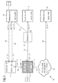
- Figure 1 shows a telecommunications system 10, the a reference telecommunications system 12, four Telecommunications systems 14 to 20, a multiplex unit 22 and includes a transparent transmission section 24.
- the telecommunications systems 12 and 14 are by a Line 26 connected.
- the telecommunications systems 14 and 16 are connected by two lines 28 and 30, which form two independent transmission links.
- a line 32 runs from the telecommunications system 12 to the multiplex unit 22 A line 32 runs.
- the multiplex unit 22 goes a line 34 to the telecommunications system 16 and a Line 36 to the telecommunications system 18. Also lies a line 38 between the telecommunications system 12 and the transparent transmission section 24.
- a line 40 leads from the transparent transmission section 24 to Telecommunication system 20.
- the telecommunications systems 12 to 20 are used for Mediation within the private network of the operator of the Telecommunications systems 12 to 20, for example one larger company.
- the multiplex unit 22 orders one fixed procedure or according to an adjustable Move transmission channels on line 32 to Transmission channels on line 34 and 36 too.
- the multiplex unit orders in reverse Transmission direction 22 also transmission channels on the Lines 34 and 36 to transmission channels on the line 32 to.
- the transparent transmission section 24 is a data transmission network in which the data are transmitted in accordance with ATM (Asynchronous Transfer Mode).
- the transparent transmission section 24 is a data transmission network that provides functions of a virtual private data transmission network.
- functions are performed a telecommunications system and a telecommunications system network by one or several public exchanges, including exchanges of the EWSD type (electronically controlled d igital W ähl s ystem) SIEMENS AG.
- the telecommunications systems 12 to 20 were in this Sequence of call identifiers NAC1 to NAC6 with the values 901, 902, 903, 904 and 906 assigned. With the help of Call indicators NAC1 to NAC6 can be Select telecommunications systems 12 to 20 directly.
- Node numbers # 1, # 2, # 3, # 4 and # 6 are defined.
- the Node numbers mentioned are greatly simplified. In fact, for example, node numbers are used that have several parts to include hierarchies in the Take into account the telecommunications system network 10 can, e.g. the node number 1-1-250, the first Number a so-called domain and the second number one designate so-called subdomain. The third number denotes then the respective telecommunications system.
- Line port numbers 1-1 through 6-1 set to the Connections of lines 26 to 40 in each To designate telecommunications systems 12 to 20.
- This too Information is simplified because it is actually Line connection numbers are used, for example four Have components, e.g. the line number 1-1-19-1, where the first part a control cabinet, the second part one Frame in the control cabinet, the third part of an insert in the frame and the fourth part from a circuit set denote the inset.
- the Lines 26, 32 and 38 in this order in the reference telecommunications system 12 line connection numbers 1-1, 1-2 and 1-3.
- the lines 28, 30 and 26 have in the Telecommunication system 14 in this order Line port numbers 2-1, 2-2 and 2-3.
- the lines 28, 30, 34 have in this order in the Telecommunication system 16 line connection numbers 3-1, 3-2 and 3-3.
- Line 36 has in the telecommunications system 18 a line terminal number 4-1.
- the line 40 has in the telecommunication system 20 the line connection number 6-1.
- Line connection numbers 1-1 to 6-1 are Line connection numbers 1-1 to 6-1 in the exemplary embodiment greatly simplified.
- the first parts of the Line port numbers usually do not match the Node numbers # 1 to # 6 match.
- each telecommunications system internal line numbers I1 to I3 for internal Designation of the connected lines or connections itself.
- lines 26, 32 and 38 are in the telecommunications system 12 with the internal Line identification I1, I2 or I3 designated.
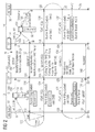
- FIG. 2 shows process steps for determining the Node number required for the telecommunications system 14 has been awarded based on the reference telecommunications system 12.
- the Telecommunication system 14 contains one Connection control unit 54 and a maintenance unit 56.
- Four timelines Z0 to Z6 relate to it Order of events in the maintenance unit 50, the Connection control unit 52, the Connection control unit 54 and the maintenance unit 56. Later times lie on the timelines Z0 to Z6 further down than earlier times.
- the dynamic Line records 60 and 62 contain data related to get the line 26. This data is only for short Periods and possibly only for individual over the Line 26 established connections valid. In contrast to there are still static line records that are permanent for the line 26 are valid. For example, in one for the line 26 in the telecommunications system 12 stored static line data set, which is shown in FIG is not shown, notes that the line 26 in the methods explained using FIG. 2 are included should.
- connection control unit 52 determines depending on the destination number, for example depending on the number of one Subscriber TlnB, the line 26 in a routing process than the line to be used for establishing the connection.
- the Connection control unit 52 checks the value of the bit position 70 of the dynamic passion record for the determined Line 26, see arrow 100.
- Connection setup message 102 is used to set up a Call connection between one to the Telecommunications system 12 connected terminal one Participant TlnA to the telecommunications system 16 connected terminal of a subscriber TlnB, see also Figure 1. Otherwise, the connection setup message is fulfilled 102 those specified in the QSIG standard for SETUP messages Requirements. For example, the Connection setup message 102 also as the destination number Telephone number of the subscriber TlnB.
- connection setup message 102 is sent via the line 26 transferred to the telecommunications system 14 and there by Connection control unit 54 processed. Due to the in the connection setup message 102 contained Information elements NodePartyNumber.inv sets the Connection control unit 54 at a time t4 in the Line data record 62, a bit position 104 of the value NULL the value ONE, see also arrow 106.
- the line data record 62d is assigned to line 26, i.e. the line through which the connection setup message 102 in the Telecommunications system 14 has been received.
- the connection control unit 54 processes the Connection setup message 102 according to the QSIG protocol, so that another connection setup message 108 to the Telecommunications system 16 is sent.
- the further one Connection setup message 108 contains none Information element NodePartyNumber.inv.
- connection message 110 which confirms that the Participant TlnB has lifted the handset of his phone.
- the Connection message 110 is a CONNECT message according to the Protocol QSIG and does not contain any of the protocol specifications additional information elements.
- the Call control unit 54 after the transmission of the Call identifier NAC2 the value of bit position 104 to the value ZERO. Otherwise, the connection message 112 is as in Standard QSIG required for a CONNECT message built up.
- Time control unit 120 Due to the reception of the signaling message 116 at a time t12 from the maintenance unit 50 Time control unit 120 started after a Predeterminable time expires, for example after 10 seconds. Occur before the timer 120 expires specified time on further assignments on line 26, so is in the associated connection setup messages due to the value ONE of bit position 70 of the Connection control unit 52 each the information element NodePartyNumber.inv inserted. In the embodiment via line 26, however, only the telecommunications system 14 reachable, of which due to the within the Time interval again and again set the value of the Bit position 104 further call identifiers NAC2 are transmitted. However, since there is already an entry in partner table 150 no further entries are created. In the Implementation of the method explained with reference to FIG.
- connection control unit 52 needs due to the in of the request message 124 contained internal Line identifier I1 no routing because the line 26 to be used for forwarding directly via the internal line identifier I1 can be determined.
- the pseudo connection message contains standard data fields 134 an information element NodeInfo.res, in which except for the internal Line identifier I1 in the reply message 132 contained data are also included. additionally contains the pseudo connection message 134 that Call number of the telecommunication system 14.
- the pseudo connection message 134 is via line 26 to Telecommunications system 12 transmitted and there from the Connection control unit 52 processed. To a Time t26 generates the connection control unit 52 based on the pseudo connection setup message 134 Reply message 136.
- the response message 136 contains the internal one Line identifier I1 of line 26 and that Call number NAC2 of the telecommunications system 14.
- the Reply message 136 is also the data of the Information element NodeInfo.res of the pseudo connection message 134 included.
- the reply message 136 at a time t30 by the maintenance unit 50 received and evaluated.
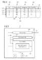
- the maintenance unit 50 contributes the node number # 2 in the evaluation in the partner table the telecommunications system 14 and the line 26 with the internal line identifier I1 on the side of the Telecommunication system 28 belonging line connection number 2-3 a, see also Figure 3.
- the maintenance unit 50 At a time t32, the maintenance unit 50 generates one Abort message 138, also called a FEAT_ABORT message referred to as.
- the abort message 138 is to the Connection control unit 52 directed and leads there a time t34 to an abort message 140, which according to QSIG protocol using the pseudo connection setup message 128 and the pseudo connection message 134 requested system resources releases.
- the abort message 140 is also called a RELEASE message designated.
- I1 to I3 are the assigned to the telecommunications system 12 Line connection numbers by the internal Line identifier I1 to I3 designated lines noted.
- line 26 with line code I1 For example, line port number 1-1 is noted.
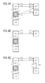
- Figures 4A to 4C show for the Telecommunication system network 10 determined network topologies in the case of FIG. 4A before a fault, in the case of FIG. 4B during a fault and in the case of Figure 4C after the Execution of a transitional measure until the final one Eliminate the fault.
- the method explained with reference to FIG. 2 is not only for the reference telecommunications system 12 but also for the other telecommunications systems 14 to 20 of Telecommunications system network 10 performed.
- the one there generated partner tables 150 become a central Computer unit transmitted and there for graphic display the network topology evaluated.
- the result is in Figure 4A shown.
- the telecommunication systems are through their Node numbers # 1 to # 6.
- the Line connections are by line connection numbers 1-1 referred to 6-1.
- the multiplex unit 22 and the transparent transmission section 24 are not shown, because the method according to the invention is not carried out in them becomes.
- the method according to the invention is used in each case Commissioning of a telecommunications system 12 to 20 executed so that all telecommunications systems 12 to 20 be taken into account when recording the network topology.
- the method according to the invention is carried out regularly Distances in the individual telecommunications systems 12 to 20 executed, both a synchronous execution as Asynchronous execution is also possible.
- execution i.e. on so - called polling, is also achieved that disturbances or the decommissioning of a telecommunications system are recorded automatically.
- the Multiplex unit 22 fails.
- the central computer unit After performing the im previous section explained procedures in all Telecommunications systems 12 to 20 and the transmission of updated partner tables 150 to the central Computer unit, the central computer unit generates the in Figure 4B shows the network topology, e.g. on a display unit.
- the two directly from the Telecommunication system 12 with the node number # 1 for Telecommunications system 16 with node number # 3 or to the telecommunications system 18 with the node number # 4 leading transmission lines 34 and 36 are no longer shown. Due to the change in network topology an error message is automatically generated by the central computer, that indicates a malfunction. To eliminate the fault a new connection will be established between the Telecommunications system 16 with node number # 3 and the telecommunications system 18 with the node number # 4 connected.
- a transmission link 180 is now located directly between the telecommunications systems 16 and 18 and the Telecommunications systems with node numbers # 3 and # 4.
- the line connection number was the Transmission path 180 on the side of the Telecommunication system 16 the line connection number 3-4 and on the side of the telecommunications system 18 Assigned to line port number 4-2.
- FIG. 5 shows the structure of the reference telecommunications system 12 with regard to the implementation of the invention Procedural units involved.
- the Telecommunication system 12 contains a transmission unit 200, a receiving unit 202 and a control unit 204.
- the transmission unit 200 is used to transmit the data in the Telecommunications system 12 generated Signaling messages on line 26 and others connected to the telecommunications system 12 Lines, e.g. line 32.
- the receiving unit 202 is used to receive the for Telecommunications system 12 determined Signaling messages on the to the Telecommunications system 12 connected lines 26, 32 and 38.
- the incoming signaling messages are from the receiving unit 202 to the control unit 204 forwarded, see arrow 206.
- the control unit 204 evaluates the received ones Signaling messages according to the QSIG protocol from and controls the transmission unit 200 so that according to the protocol Reply messages are generated, see arrow 208.
- the Control unit 204 contains the maintenance unit 50 and the Connection control unit 52.
- the control unit 204 stores the partner table 150 in a storage unit 210 down, see arrow 212.
- the functions of the transmission unit 200, the reception unit 202 and the control unit 204 are used in the exemplary embodiment Aid is provided by circuits that have no programs To run.
- Aid is provided by circuits that have no programs To run.
- the method explained with reference to FIG. 2 can be run regardless of whether the partner telecommunications system 28 a transit telecommunication system or is an end telecommunication system, i.e. a Telecommunication system on which the called subscriber connected.
- the reference telecommunications system can a transit telecommunication system or an initial telecommunication system be, i.e. a Telecommunication system on which the calling subscriber connected.
- it is not necessary that the connection message 112 due to the Connection establishment message 102 is generated. The important thing is that the connection message 102 on a line 26 is transmitted for which bit position 104 or one of the Bit position 104 corresponding bit position has the value ONE.
Landscapes
- Engineering & Computer Science (AREA)
- Computer Networks & Wireless Communication (AREA)
- Telephonic Communication Services (AREA)
- Data Exchanges In Wide-Area Networks (AREA)
Abstract
Description
- Figur 1
- einen Telekommunikationsanlagenverbund mit einer Bezugs-Telekommunikationsanlage,
- Figur 2
- Verfahrensschritte zum Ermitteln der Telekommunikationsanlagennummer einer der Bezugs-Telekommunikationsanlage benachbarten Telekommunikationsanlage,
- Figur 3
- eine Partnertabelle zum Speichern der ermittelten Telekommunikationsanlagennummer,
- Figuren 4A bis 4C
- für den Telekommunikationsanlagenverbund ausgehend von mehreren Partnertabellen ermittelte Netztopologien vor einer Störung, während einer Störung und nach der Ausführung einer Übergangsmaßnahme bis zur Beseitigung der Störung, und
- Figur 5
- den Aufbau der Bezugs-Telekommunikationsanlage.
die Signalisierungsnachricht 116 ist an die Wartungseinheit 50 gerichtet und enthält als Parameter:
- das interne Leitungskennzeichen I1 der Leitung 26,
- das mit der Verbindungsnachricht 112 übermittelte Rufkennzeichen NAC2 der Telekommunikationsanlage 14.
- das interne Leitungskennzeichen I1,
- das Rufkennzeichen NAC2, und
- ein Kommando AM CMD, mit dem weitere Kennzeichendaten angefordert werden.
- Ursprungsrufnummer: NAC1,
- Zielrufnummer: NAC2,
- ein Informationsfeld NodeInfo.inv in dem das Kommando AM CMD enthalten ist.
- das interne Leitungskennzeichen I3, und
- das Kommando AM CMD.
- die Netzknotennummer #2, der Telekommunikationsanlage 14, in der sich die Wartungseinheit 56 befindet, und
- die zum internen Kennzeichen I3 gehörende Leitungsanschlussnummer 2-3 der Leitung 26 in der Telekommunikationsanlage 14.
- das interne Leitungskennzeichen I3,
- das Kommando AM CMD,
- die Netzknotennummer #2, und
- die Leitungsanschlussnummer 2-3.
- internes Leitungskennzeichen I1,
- Rufkennzeichen der benachbarten Telekommunikationsanlage 14: 902,
- Netzknotennummer der benachbarten Telekommunikationsanlage 14: #2, und
- Leitungsanschlusskennzeichen in der benachbarten Telekommunikationsanlage 14: 2-3. Wird das an Hand der Figur 2 erläuterte Verfahren für die Leitung 32 ausgeführt, so entstehen Einträge in den Zeilen 154 und 156. Beim Durchführen des Verfahrens für die Leitung 38 entstehen die Einträge in der Zeile 158.
Claims (20)
- Verfahren zum Übermitteln eines Kennzeichendatums (NAC2, #2) einer Netzknoteneinheit (14),
bei dem eine Übertragungsstrecke (26) zwischen einer Bezugs-Netzknoteneinheit (12) und einer Partner-Netzknoteneinheit (14) eines Datenübertragungsnetzes (10) liegt,
bei dem über die Übertragungsstrecke (26) von der Bezugs-Netzknoteneinheit (12) zu der Partner-Netzknoteneinheit (14) mindestens eine Signalisierungsnachricht (102) übertragen wird, die zur Verbindungssteuerung für die Übertragung von Nutzdaten zwischen zwei Endgeräten (TlnA, TlnB) des Datenübertragungsnetzes (10) dient,
bei dem in die Signalisierungsnachricht (102) automatisch ein Nachrichtenelement eingefügt wird, mit dem die Übertragung eines Kennzeichendatums (NAC2) angefordert wird, das die Partner-Netzknoteneinheit (14) oder einen Bestandteil der Partner-Netzknoteneinheit (14) kennzeichnet,
und bei dem das Kennzeichendatum von der Partner-Netzknoteneinheit (14) zu der Bezugs-Netzknoteneinheit (12) mit einer Rück-Signalisierungsnachricht (112) übertragen wird. - Verfahren nach Anspruch 1, dadurch gekennzeichnet, dass das Kennzeichendatum ein Verbindungskennzeichen (NAC2) ist, mit dessen Hilfe eine Anforderung an die Partner-Netzknoteneinheit (14) gestellt werden kann.
- Verfahren nach Anspruch 2, dadurch gekennzeichnet, dass automatisch mit Hilfe des Verbindungskennzeichens (NAC2) von der Bezugs-Netzknoteneinheit (12) an die Partner-Netzknoteneinheit (14) eine Anforderung (128) zur Übertragung mindestens eines weiteren Kennzeichendatums (#2) gestellt wird, das die Partner-Netzknoteneinheit (14) oder einen Bestandteil der Partner-Netzknoteneinheit (14) kennzeichnet,
und dass das weitere Kennzeichendatum (#2) von der Partner-Netzknoteneinheit (14) zur Bezugs-Netzknoteneinheit (12) übertragen wird. - Verfahren nach einem der vorhergehenden Ansprüche, dadurch gekennzeichnet, dass das Kennzeichendatum (NAC2) und/oder das weitere Kennzeichendatum (#2) für das Erfassen der Topologie und/oder zum Festlegen von Weiterleitungstabellen verwendet werden.
- Verfahren nach einem der vorhergehenden Ansprüche, dadurch gekennzeichnet, dass das Verfahren in mehreren Netzknoteneinheiten (12 bis 20) ausgeführt wird,
und/oder dass die Kennzeichendaten (NAC) und/oder die weiteren Kennzeichendaten (#1 bis #6) zentral gesammelt werden. - Verfahren nach einem der vorhergehenden Ansprüche, dadurch gekennzeichnet, dass das Datenübertragungsnetz (10) ein durchschaltevermitteltes Datenübertragungsnetz (10) ist, in dem abhängig von den Signalisierungsdaten Übertragungsstrecken und/oder Übertragungskanäle von Übertragungsstrecken verschaltet werden,
und/oder dass die Übertragungsstrecke (26) eine Leitung oder eine Funkübertragungsstrecke ist,
und/oder dass die Netzknoteneinheit (12 bis 20) abhängig von der Signalisierungsnachricht (102) Vermittlungsfunktionen erbringt und/oder dass die Netzknoteneinheit eine Nebenstellenanlage (12 bis 20) eines Nebenstellenanlagenverbundes (10) ist,
und/oder dass die Nutzdaten Gesprächsdaten oder andere Anwenderdaten sind. - Verfahren nach einem der vorhergehenden Ansprüche, dadurch gekennzeichnet, dass die Signalisierungsnachricht (102) eine Verbindungsaufbaunachricht ist und/oder dass die Rück-Signalisierungsnachricht (112) einen Verbindungsaufbau bestätigt,
und/oder dass die Signalisierungsnachricht (102) und/oder die Rück-Signalisierungsnachricht (112) gemäß dem Protokoll ISUP oder dem Protokoll QSIG oder gemäß einem auf einem dieser Protokolle aufbauenden Protokoll übermittelt wird. - Verfahren nach einem der Ansprüche 3 bis 7, dadurch gekennzeichnet, dass das weitere Kennzeichendatum (#2) ohne Aufbau einer zusätzlichen Nutzdatenverbindung angefordert und übermittelt wird (128).
- Verfahren nach einem der Ansprüche 3 bis 8, dadurch gekennzeichnet, dass ein weiteres Kennzeichendatum (3-2) zur Kennzeichnung des Anschlusses der Übertragungsstrecke (26) in der Partner-Netzknoteneinheit (14) angefordert und übertragen wird,
und/oder dass ein weiteres Kennzeichendatum (#2) zur Kennzeichnung der Partner-Netzknoteneinheit (14) angefordert und übertragen wird,
und/oder dass das weitere Kennzeichendatum (3-2) zur Kennzeichnung des Anschlusses und/oder dass das weitere Kennzeichendatum (#2) zur Kennzeichnung der Partner-Netzknoteneinheit für die Wartung des Datenübertragungsnetzes (10) festgelegt worden ist. - Verfahren nach einem der Ansprüche 3 bis 9, dadurch gekennzeichnet, dass eine Erfassungszeitdauer (120) vorgegeben wird,
dass während der Erfassungszeitdauer (120) das Verfahren abhängig von den während der Erfassungszeitdauer (120) auftretenden Signalisierungsnachrichten (102, 112) für mehrere Übertragungsstrecken (26 bis 32) der Bezugs-Netzknoteneinheit (12) und/oder mehrmals pro Übertragungsstrecke (32) ausgeführt wird,
und/oder dass die für die Erfassungszeitdauer (120) empfangenen Kennzeichendaten (NAC) vorzugsweise mit ihrer Zuordnung zu einer Übertragungsstrecke (26, 32) gespeichert werden,
und/oder dass nach Ablauf der Erfassungszeitdauer (120) die weiteren Kennzeichendaten (#2) mit Hilfe der gespeicherten Kennzeichendaten (NAC) angefordert werden (128). - Verfahren nach Anspruch 10, dadurch gekennzeichnet, dass vor Beginn der Erfassungszeitdauer (120) ein Vermerk (70) vorzugsweise in einem der Übertragungsstrecke (26) zugeordneten Datensatz (60) gespeichert wird,
dass abhängig vom Vermerk (70) das Nachrichtenelement in die Signalisierungsnachricht (102) eingefügt wird,
dass beim Fehlen des Vermerks (70) das Nachrichtenelement nicht in die Signalisierungsnachricht (102) eingefügt wird,
und/oder dass die Rück-Signalisierungsnachricht (112) den Beginn der Erfassungszeitdauer (120) festlegt,
und dass der Vermerk (70) erst am Ende der Erfassungszeitdauer (120) entfernt wird. - Verfahren nach Anspruch 10 oder 11, dadurch gekennzeichnet, dass in der Partner-Netzknoteneinheit (14) ein Vermerk (104) vorzugsweise in einem der Übertragungsstrecke (26) zugeordneten Datensatz (26) gespeichert wird, wenn das Nachrichtenelement empfangen wird,
dass abhängig von dem Vermerk (104) das Kennzeichendatum (NAC) in eine Rück-Signalisierungsnachricht (112) eingefügt wird,
dass beim Fehlen des Vermerks (104) in Rück-Signalisierungsnachrichten (112) kein Kennzeichendatum eingefügt wird,
und dass der Vermerk (104) beim Übertragen einer Rück-Signalisierungsnachricht (112) mit einem Kennzeichendatum (NAC) entfernt wird. - Verfahren nach einem der vorhergehenden Ansprüche, dadurch gekennzeichnet, dass für mindestens eine an der Bezugs-Netzknoteneinheit (12) angeschlossene Übertragungsstrecke (26) vermerkt wird, dass ein Verfahren nach einem der vorhergehenden Ansprüche ausgeführt werden soll,
und/oder dass für mindestens eine an der Bezugs-Netzknoteneinheit (12) angeschlossene Übertragungsstrecke (26) vermerkt wird, dass ein Kennzeichendatum nur manuell vorgegeben wird,
und/oder dass für mindestens eine an der Bezugs-Netzknoteneinheit (12) angeschlossene Übertragungsstrecke (26) vermerkt wird, dass ein Wechsel von einer manuellen Vorgabe zu einem automatischen Erfassen eines Kennzeichendatums zulässig ist. - Verfahren nach einem der vorhergehenden Ansprüche, dadurch gekennzeichnet, dass zwischen der Bezugs-Netzknoteneinheit (12) und der Partner-Netzknoteneinheit (14) keine weitere Netzknoteneinheit liegt, in welcher zumindest die auf die Partner-Netzknoteneinheit (14) bezogenen Verfahrensschritte eines Verfahrens nach einem der Ansprüche 1 bis 13 ausgeführt werden.
- Verfahren nach einem der vorhergehenden Ansprüche, dadurch gekennzeichnet, dass zwischen der Bezugs-Netzknoteneinheit (12) und der Partner-Netzknoteneinheit (14) eine Multiplexeinheit (22) liegt, die vorzugsweise im Rahmen eines Zeitmultiplexverfahrens eine Multiplexfunktion und/oder eine Demultiplexfunktion für die Übertragungsstrecke (32) und mindestens zwei weitere an die Multiplexeinheit (22) angeschlossene Übertragungsstrecken (34, 36) erbringt.
- Verfahren nach einem der vorhergehenden Ansprüche, dadurch gekennzeichnet, dass die Übertragungsstrecke (38) zu einem weiteren Datenübertragungsnetz (24) führt, für das ein anderes Signalisierungsverfahren zur Verbindungssteuerung festgelegt worden ist,
und dass die Signalisierungsnachrichten des Datenübertragungsnetzes in ihrer Struktur und in ihrem Wert unverändert über das weitere Datenübertragungsnetz (24) übertragen werden,
und/oder dass das weitere Datenübertragungsnetz die Funktion eines virtuellen Privatnetzes erbringt. - Verfahren nach einem der vorhergehenden Ansprüche, dadurch gekennzeichnet, dass das Verfahren wiederholt, vorzugsweise periodisch, für eine Übertragungsstrecke ausgeführt wird, über die noch keine Rück-Signalisierungsnachricht empfangen worden ist,
und/oder dass für eine Übertragungsstrecke, für die eine Rück-Signalisierungsnachricht empfangen worden ist, wiederholt, vorzugsweise periodisch, geprüft wird, ob die Partner-Netzknoteneinheit weiterhin über die Übertragungsstrecke erreichbar ist. - Vorrichtung (12), insbesondere vermittlungstechnische Einrichtung,
mit mindestens einer Anschlusseinheit (1-1) für den Anschluss einer Übertragungsstrecke (26), die zu einer Partner-Netzknoteneinheit (12) führt,
mit einer Sendeeinheit (200), die über die Übertragungsstrecke (26) mindestens eine Signalisierungsnachricht (102) sendet, die zur Verbindungssteuerung für die Übertragung von Nutzdaten zwischen zwei Endgeräten (TlnA, TlnB) eines Datenübertragungsnetzes (10) dient,
mit einer Empfangseinheit (202), die über die Übertragungsstrecke (26) eine Rück-Signalisierungsnachricht (112) empfängt, die ebenfalls zur Verbindungssteuerung für die Übertragung von Nutzdaten dient,
und mit einer Steuereinheit (204) zum Ansteuern der Sendeeinheit (200) und der Empfangseinheit (202),
dadurch gekennzeichnet, dass die Steuereinheit (204) eine Kennzeichendatenerfassungseinheit (50) enthält, die in die Signalisierungsnachricht (102) automatisch ein Nachrichtenelement einfügt, mit dem die Übertragung eines Kennzeichendatums (NAC) angefordert wird, das die Partner-Netzknoteneinheit (14) oder einen Bestandteil der Partner-Netzknoteneinheit (14) kennzeichnet,
und/oder dass die Kennzeichendatenerfassungseinheit (50) nach dem Empfang des Kennzeichendatums (NAC) in der Rück-Signalisierungsnachricht (112) mit Hilfe des Kennzeichendatums (NAC) von der Partner-Netzknoteneinheit (14) mindestens ein weiteres Kennzeichendatum (#2) zur Kennzeichnung der Partner-Netzknoteneinheit (14) oder eines Bestandteils der Partner-Netzknoteneinheit (14) anfordert und von der Empfangseinheit (202) entgegennimmt. - Vorrichtung (12) nach Anspruch 18, dadurch gekennzeichnet, dass die Vorrichtung weitere Einheiten enthält, die mindestens einen auf die Bezugs-Netzknoteneinheit (12) bezogenen Verfahrensschritt nach einem der Ansprüche 1 bis 17 ausführt.
- Programm mit einer Befehlsfolge dadurch gekennzeichnet, dass bei der Ausführung der Befehlsfolge durch einen Prozessor (P1) ein Verfahren nach einem der Ansprüche 1 bis 17 ausgeführt wird.
Applications Claiming Priority (2)
| Application Number | Priority Date | Filing Date | Title |
|---|---|---|---|
| DE10159261 | 2001-12-03 | ||
| DE10159261A DE10159261A1 (de) | 2001-12-03 | 2001-12-03 | Verfahren zum Übermitteln eines Kennzeichendatums für eine Netzknoteneinheit, zugehörige Vorrichtung und zugehöriges Programm |
Publications (3)
| Publication Number | Publication Date |
|---|---|
| EP1317150A2 true EP1317150A2 (de) | 2003-06-04 |
| EP1317150A3 EP1317150A3 (de) | 2007-08-22 |
| EP1317150B1 EP1317150B1 (de) | 2015-10-21 |
Family
ID=7707834
Family Applications (1)
| Application Number | Title | Priority Date | Filing Date |
|---|---|---|---|
| EP02102529.1A Expired - Lifetime EP1317150B1 (de) | 2001-12-03 | 2002-11-04 | Verfahren zum Übermitteln eines Kennzeichendatums einer Netzknoteneinheit, zugehörige Vorrichtung und zugehöriges Programm |
Country Status (3)
| Country | Link |
|---|---|
| US (1) | US7486668B2 (de) |
| EP (1) | EP1317150B1 (de) |
| DE (1) | DE10159261A1 (de) |
Families Citing this family (3)
| Publication number | Priority date | Publication date | Assignee | Title |
|---|---|---|---|---|
| US8306199B2 (en) * | 2006-10-20 | 2012-11-06 | Nokia Corporation | Accounting in a transit network |
| US8400452B2 (en) * | 2008-05-08 | 2013-03-19 | Motorola Solutions, Inc. | Method and system for segmented propagation visualization |
| ES2739665T3 (es) * | 2016-03-02 | 2020-02-03 | Kyynel Oy | Adaptación de enlace en comunicaciones inalámbricas |
Family Cites Families (11)
| Publication number | Priority date | Publication date | Assignee | Title |
|---|---|---|---|---|
| US5377262A (en) | 1991-12-30 | 1994-12-27 | At&T Corp. | Telecommunication switching system having adaptive routing switching nodes |
| US5229717A (en) * | 1992-05-22 | 1993-07-20 | General Electric Company | Simultaneous two-contrast fast spin echo NMR imaging |
| US5499290A (en) * | 1993-01-28 | 1996-03-12 | Bellsouth Corporation | AIN non-call associated signalling for service nodes and service control points in a telephone system |
| US5592477A (en) * | 1994-09-12 | 1997-01-07 | Bell Atlantic Network Services, Inc. | Video and TELCO network control functionality |
| WO1996013927A1 (en) * | 1994-10-27 | 1996-05-09 | Telefonaktiebolaget Lm Ericsson | System and method of providing enhanced subscriber services in a multi-node telecommunication network |
| US5541513A (en) * | 1995-04-14 | 1996-07-30 | General Electric Company | MRI center point artifact elimination using realtime receiver phase control |
| US5672969A (en) * | 1996-04-25 | 1997-09-30 | General Electric Company | Reduction of Nyquist ghost artifacts in oblique echo planar imaging |
| US6728205B1 (en) * | 1997-02-19 | 2004-04-27 | Massachusetts Institute Of Technology | Method and apparatus for automatic protection switching |
| US6137876A (en) | 1997-12-04 | 2000-10-24 | Ericsson Inc | Network call trace |
| US6658022B1 (en) * | 1998-09-30 | 2003-12-02 | Cisco Technology, Inc. | Signaling protocol for controlling voice calls in a packet switching network |
| US6327358B1 (en) * | 1999-04-27 | 2001-12-04 | Nortel Networks Limited | System and method for rerouting data calls to internet service provider via lowest access point in a telephone network |
-
2001
- 2001-12-03 DE DE10159261A patent/DE10159261A1/de not_active Withdrawn
-
2002
- 2002-08-20 US US10/225,210 patent/US7486668B2/en not_active Expired - Fee Related
- 2002-11-04 EP EP02102529.1A patent/EP1317150B1/de not_active Expired - Lifetime
Non-Patent Citations (1)
| Title |
|---|
| None |
Also Published As
| Publication number | Publication date |
|---|---|
| EP1317150B1 (de) | 2015-10-21 |
| EP1317150A3 (de) | 2007-08-22 |
| US20030103531A1 (en) | 2003-06-05 |
| US7486668B2 (en) | 2009-02-03 |
| DE10159261A1 (de) | 2003-06-18 |
Similar Documents
| Publication | Publication Date | Title |
|---|---|---|
| DE69632888T2 (de) | Dienst- und Informationsverwaltungssystem für ein Telekommunikationsnetzwerk | |
| DE69028502T2 (de) | Vorrichtung zur Weglenkung von Paketnachrichten | |
| DE3903257C2 (de) | ||
| EP0766443A2 (de) | Verfahren zur Ermittlung von freien Agenten-Kommunikationsendgeräten in Kommunikationsnetzen mit einer automatischen Anrufverteilung | |
| DE60030273T2 (de) | Verfahren und systeme zur lenkung von zeichengabenachrichten in einem kommunikationsnetz unter verwendung von sprechkreisadress (cic)-information | |
| EP2469885B1 (de) | Verfahren zur Integration von Funktionen eines Telekommunikationsnetzes in ein Datennetz | |
| DE60032070T2 (de) | Architektur zur Bereitstellung von Leistungsmerkmalen für drahtlose Anrufe in einem drahtlosen Telekommunikationssystem | |
| EP1207670A2 (de) | Dienst zur automatischen Übermittlung von Paketdaten | |
| EP1387589A1 (de) | Media Gateway zur Bereitstellung der PSTN/ISDN Dienste in Netzwerken der nächsten Generation | |
| EP1317150B1 (de) | Verfahren zum Übermitteln eines Kennzeichendatums einer Netzknoteneinheit, zugehörige Vorrichtung und zugehöriges Programm | |
| DE60127450T2 (de) | Verfahren zum einrichten von kommunikationswegen zwischen zugriffspunkten eines vermittlungssystems und das verfahren implementierendes vermittlungssystem | |
| EP0923254A2 (de) | Verfahren zur Beschaffung von Instruktionen bezüglich eines Zielteilnehmers in einem Telekommunikationsnetz und Knotenpunkte hierfür | |
| WO2000021309A1 (de) | Verfahren zur behandlung von in-calls bei in-dienstrufnummernportabilität | |
| DE69836658T2 (de) | Gerät und Verfahren für Kommunikationsinhaltsaufzeichnung | |
| EP1407621B1 (de) | Vorrichtung zum übertragen von zeichengabemeldungen | |
| DE19827285A1 (de) | Verfahren, Server und Kommunikationsknoten zum Aufbau gebührenoptimierter Kommunikationsverbindungen | |
| WO2001091430A1 (de) | Verfahren und kommunikationsanordnung zum vermitteln von kommunikationsbeziehungen an in zumindest einem kommunikationsnetz angeordnete und zumindest einer gruppe zugeordnete teilnehmeranschlüsse | |
| EP1535477B1 (de) | Verfahren zum weiterleiten von signalisierungsnachrichten und zugehörige komponenten | |
| EP1311101A1 (de) | Bereitstellung von IVR Ressourcen in BICC Netzen | |
| EP1502448B1 (de) | Verfahren zum erfassen von anrufen und zugehörige einheiten | |
| DE602004004923T2 (de) | Verfahren zur Herstellung einer Direktkoordinationsverbindung zwischen einer ersten und einer zweiten Steuerzentrale zur Ausführung von Diensten | |
| EP1225753B1 (de) | Verteiltes automatisches Anrufverteilsystem mit Notfall-Betriebsart | |
| DE10145987A1 (de) | Verfahren zur Auswahl eines Leistungsmerkmals und zugehörige Einheiten | |
| DE19742582C1 (de) | Verfahren und Telekommunikationsanlage zum Verteilen von Daten in einem Telekommunikationsnetz | |
| DE60320585T2 (de) | Verfahren und Anordnung zur Auswahl einer Verbindung zwischen einem Zugangsnetz und einer Ortsvermittlungsstelle |
Legal Events
| Date | Code | Title | Description |
|---|---|---|---|
| PUAI | Public reference made under article 153(3) epc to a published international application that has entered the european phase |
Free format text: ORIGINAL CODE: 0009012 |
|
| AK | Designated contracting states |
Designated state(s): AT BE BG CH CY CZ DE DK EE ES FI FR GB GR IE IT LI LU MC NL PT SE SK TR |
|
| AX | Request for extension of the european patent |
Extension state: AL LT LV MK RO SI |
|
| PUAL | Search report despatched |
Free format text: ORIGINAL CODE: 0009013 |
|
| AK | Designated contracting states |
Kind code of ref document: A3 Designated state(s): AT BE BG CH CY CZ DE DK EE ES FI FR GB GR IE IT LI LU MC NL PT SE SK TR |
|
| AX | Request for extension of the european patent |
Extension state: AL LT LV MK RO SI |
|
| 17P | Request for examination filed |
Effective date: 20080220 |
|
| AKX | Designation fees paid |
Designated state(s): DE FR GB IT |
|
| RAP1 | Party data changed (applicant data changed or rights of an application transferred) |
Owner name: SIEMENS ENTERPRISE COMMUNICATIONS GMBH & CO. KG |
|
| 17Q | First examination report despatched |
Effective date: 20110725 |
|
| RAP1 | Party data changed (applicant data changed or rights of an application transferred) |
Owner name: UNIFY GMBH & CO. KG |
|
| GRAP | Despatch of communication of intention to grant a patent |
Free format text: ORIGINAL CODE: EPIDOSNIGR1 |
|
| INTG | Intention to grant announced |
Effective date: 20150422 |
|
| GRAS | Grant fee paid |
Free format text: ORIGINAL CODE: EPIDOSNIGR3 |
|
| GRAA | (expected) grant |
Free format text: ORIGINAL CODE: 0009210 |
|
| AK | Designated contracting states |
Kind code of ref document: B1 Designated state(s): DE FR GB IT |
|
| REG | Reference to a national code |
Ref country code: GB Ref legal event code: FG4D Free format text: NOT ENGLISH |
|
| REG | Reference to a national code |
Ref country code: DE Ref legal event code: R081 Ref document number: 50216097 Country of ref document: DE Owner name: UNIFY GMBH & CO. KG, DE Free format text: FORMER OWNER: SIEMENS AKTIENGESELLSCHAFT, 80333 MUENCHEN, DE |
|
| REG | Reference to a national code |
Ref country code: FR Ref legal event code: PLFP Year of fee payment: 14 |
|
| REG | Reference to a national code |
Ref country code: DE Ref legal event code: R096 Ref document number: 50216097 Country of ref document: DE |
|
| PGFP | Annual fee paid to national office [announced via postgrant information from national office to epo] |
Ref country code: GB Payment date: 20151126 Year of fee payment: 14 Ref country code: DE Payment date: 20151130 Year of fee payment: 14 |
|
| PGFP | Annual fee paid to national office [announced via postgrant information from national office to epo] |
Ref country code: FR Payment date: 20151127 Year of fee payment: 14 |
|
| PG25 | Lapsed in a contracting state [announced via postgrant information from national office to epo] |
Ref country code: IT Free format text: LAPSE BECAUSE OF FAILURE TO SUBMIT A TRANSLATION OF THE DESCRIPTION OR TO PAY THE FEE WITHIN THE PRESCRIBED TIME-LIMIT Effective date: 20151021 |
|
| REG | Reference to a national code |
Ref country code: DE Ref legal event code: R097 Ref document number: 50216097 Country of ref document: DE |
|
| PLBE | No opposition filed within time limit |
Free format text: ORIGINAL CODE: 0009261 |
|
| STAA | Information on the status of an ep patent application or granted ep patent |
Free format text: STATUS: NO OPPOSITION FILED WITHIN TIME LIMIT |
|
| 26N | No opposition filed |
Effective date: 20160722 |
|
| REG | Reference to a national code |
Ref country code: DE Ref legal event code: R082 Ref document number: 50216097 Country of ref document: DE Representative=s name: FRITZSCHE PATENTANWAELTE, DE Ref country code: DE Ref legal event code: R081 Ref document number: 50216097 Country of ref document: DE Owner name: UNIFY GMBH & CO. KG, DE Free format text: FORMER OWNER: UNIFY GMBH & CO. KG, 81379 MUENCHEN, DE |
|
| REG | Reference to a national code |
Ref country code: DE Ref legal event code: R119 Ref document number: 50216097 Country of ref document: DE |
|
| GBPC | Gb: european patent ceased through non-payment of renewal fee |
Effective date: 20161104 |
|
| REG | Reference to a national code |
Ref country code: FR Ref legal event code: ST Effective date: 20170731 |
|
| PG25 | Lapsed in a contracting state [announced via postgrant information from national office to epo] |
Ref country code: FR Free format text: LAPSE BECAUSE OF NON-PAYMENT OF DUE FEES Effective date: 20161130 |
|
| PG25 | Lapsed in a contracting state [announced via postgrant information from national office to epo] |
Ref country code: DE Free format text: LAPSE BECAUSE OF NON-PAYMENT OF DUE FEES Effective date: 20170601 Ref country code: GB Free format text: LAPSE BECAUSE OF NON-PAYMENT OF DUE FEES Effective date: 20161104 |