EP1317138A1 - Wireless camera - Google Patents
Wireless camera Download PDFInfo
- Publication number
- EP1317138A1 EP1317138A1 EP01963531A EP01963531A EP1317138A1 EP 1317138 A1 EP1317138 A1 EP 1317138A1 EP 01963531 A EP01963531 A EP 01963531A EP 01963531 A EP01963531 A EP 01963531A EP 1317138 A1 EP1317138 A1 EP 1317138A1
- Authority
- EP
- European Patent Office
- Prior art keywords
- circuit
- signals
- encoding
- transmission
- unit
- Prior art date
- Legal status (The legal status is an assumption and is not a legal conclusion. Google has not performed a legal analysis and makes no representation as to the accuracy of the status listed.)
- Withdrawn
Links
Images







Classifications
-
- H—ELECTRICITY
- H04—ELECTRIC COMMUNICATION TECHNIQUE
- H04N—PICTORIAL COMMUNICATION, e.g. TELEVISION
- H04N23/00—Cameras or camera modules comprising electronic image sensors; Control thereof
- H04N23/50—Constructional details
- H04N23/51—Housings
-
- H—ELECTRICITY
- H04—ELECTRIC COMMUNICATION TECHNIQUE
- H04L—TRANSMISSION OF DIGITAL INFORMATION, e.g. TELEGRAPHIC COMMUNICATION
- H04L27/00—Modulated-carrier systems
- H04L27/26—Systems using multi-frequency codes
- H04L27/2601—Multicarrier modulation systems
-
- H—ELECTRICITY
- H04—ELECTRIC COMMUNICATION TECHNIQUE
- H04N—PICTORIAL COMMUNICATION, e.g. TELEVISION
- H04N23/00—Cameras or camera modules comprising electronic image sensors; Control thereof
- H04N23/60—Control of cameras or camera modules
- H04N23/66—Remote control of cameras or camera parts, e.g. by remote control devices
Definitions
- the present invention relates to a wireless camera for use in a relaying from the spot for television broadcasting.
- wireless cameras have been used to perform a relaying from the spot for television broadcasting such as news programs, sports programs, and various event programs.
- video signals and audio signals picked up and gathered by the wireless camera are transmitted to a base relay station such as a relay car using ground waves employing radio transmission.
- a base relay station such as a relay car using ground waves employing radio transmission.
- the camera angle is spread and degree of freedom is increased, the mobility of a wireless camera is improved at the spot where a relaying for television broadcasting is performed.
- video signals and audio signals are digitized and modulated in the digital modulation manner.
- the present invention has an object to overcome the above-mentioned drawbacks of the prior art by providing a wireless camera which can be operated by single operator with its mobility desirably secured.
- a wireless camera including pick up means, encoding means for encoding video signals picked up by the pick up means to generate transmission data of a predetermined encoding system, modulation means for orthogonal frequency-division-multiplex modulating the transmission data encoded by the encoding means, and transmission means for frequency-converting modulated signals generated by the modulation means into signals of a radio frequency band, and radiating frequency-converted signals via an antenna, wherein the pick up means, the encoding means, the modulation means, and the transmission means are housed in a housing or a unitable housing.
- the wireless camera has the pick up means, the encoding means, the modulation means for performing orthogonal frequency-division-multiplex modulation, the transmission means, and the antenna housed in a housing or a unitable housing.
- a ground digital radio relay system (referred to as a radio relay system, hereinafter) to perform a relaying from the spot for television broadcasting such as news programs, sports programs, and various event programs will further be described below concerning the best modes for carrying out the present invention with reference to the accompanying drawings.
- Fig. 1 shows the configuration of a radio relay system 1 according to the present invention.
- the radio relay system 1 includes a wireless camera 11 for shooting a subject, a reception relay station 12 for receiving transmission signals from the wireless camera 11.
- the reception relay station 12 includes an external reception unit 13, an internal reception unit 14, and a plurality of IF cables 15 which connects the external reception unit 13 and the internal reception unit 14.
- the radio relay system 1 is used to perform a relaying from the spot for television broadcasting such as news programs, sports programs, and various event programs, and is a system adapted for transmitting video signals etc. of a video subject shot by the wireless camera 11 to the reception relay station 12 using ground waves employing radio transmission.
- the camera angle and shooting position are not restrained by cables etc. which connect the wireless camera 11 and the reception relay station 12. Also, the mobility of the wireless camera 11 is improved at the spot where a relaying for television broadcasting is performed.
- transport streams conforming to the MPEG 2 Systems are employed as radio transmission signals from the wireless camera 11 to the reception relay station 12, and the OFDM (Orthogonal Frequency Division Multiplex) modulation manner is employed as a modulation manner.
- OFDM Orthogonal Frequency Division Multiplex
- FIG.2 and FIG.3 show schematic views of the wireless camera 11, while FIG.4 shows a block diagram of the wireless camera 11.
- the wireless camera 11 includes a main body unit 16 provided with a pick up unit etc., an encoding/transmission unit 17 attached to the main body unit 16, and a battery unit 18 attached to the encoding/transmission unit 17.
- the encoding/transmission unit 17 is removably attached to the main body unit 16, and the battery unit 18 is also removably attached to the encoding/transmission unit 17.
- the encoding/transmission unit 17 When the encoding/transmission unit 17 is attached to the main body unit 16, the encoding/transmission unit 17 is electrically connected to the main body unit 16.
- the battery unit 18 When the battery unit 18 is attached to the encoding/transmission unit 17, the main body unit 16 and the encoding/transmission unit 17 can be supplied with electric power by the battery unit 18.
- the encoding/transmission unit 17 is provided with a transmission antenna 19.
- the transmission antenna 19 transmits video signals etc. picked up by the wireless camera 11 by employing radio transmission.
- the transmission antenna 19 is a non-directional antenna.
- the main body unit 16 includes a pick up unit 21 and a microphone 22.
- the pick up unit 21 is composed of a pick up optical system, a CCD image sensor, an A/D converter, a camera signal processing unit, etc.
- the pick up unit 21 performs analog-to-digital conversion and timing processing for video signals picked up and converted to electric signals by the CCD image sensor to generate baseband digital video signals.
- the pick up unit 21 sends thus picked up and processed baseband digital video signals and synchronization signals of the digital video signals to the encoding/transmission unit 17.
- the microphone 22 gathers audio speech or sound at respective relay spots, and digitize gathered audio signals to generate baseband digital audio signals.
- the microphone 22 sends thus gathered and processed baseband digital audio signals to the encoding/transmission unit 17.
- the encoding/transmission unit 17 includes the transmission antenna 19, an encoding/modulation unit 23, a transmission unit 24, an operation input unit 25 which is operated by the user to perform input processing, a display unit 26 for displaying set up information etc. to the user.
- the transmission unit 24 in the encoding/transmission unit 17 includes a frequency converter 27 and a high-frequency amplifier 28.
- the encoding/modulation unit 23 receives baseband digital video signals and baseband digital audio signals from the main body unit 16. Also, the encoding/modulation unit 23 receives predetermined data signals from the main body unit 16. The encoding/modulation unit 23 compresses and encodes digital video signals and digital audio signals based on the MPEG 2 Systems. Then, the encoding/modulation unit 23 multiplexes respective compressed data, other control data, etc. to generate transport streams conforming to the MPEG 2 Systems.
- the encoding/modulation unit 23 performs predetermined transmission-line-encoding or OFDM frame construction for generated transport streams such as energy diffusion, RS encoding, convolutional interleaving, inner code encoding, bit interleaving, symbol interleaving, mapping corresponding to modulation manner, and insertion of predetermined pilot signals and null signals.
- the encoding/modulation unit 23 performs OFDM modulation for transmission-line-encoded data streams such as orthogonal transformation for making 2,048 I, Q signals one symbol and performing IFFT (Inverse Fast Fourier Transform) operation to generate time-domain OFDM signals, guard interval addition for adding guard interval to time-domain OFDM signals by copying and pasting the latter half of one effective symbol to the first half thereof, orthogonal modulation for orthogonal-modulating time-domain OFDM signals to which guard interval is added to generate IF signals of an intermediate frequency band.
- the encoding/modulation unit 23 generates IF signals of an intermediate frequency band by performing the transmission-line-encoding and the OFDM modulation.
- the IF signals output from the encoding/modulation unit 23 is sent to the frequency converter 27 in the transmission unit 24.
- the frequency converter 27 in the transmission unit 24 up-converts carrier frequency of IF signals to generate RF signals for radio transmission. Then, RF signals are sent to the high-frequency amplifier 28 in the transmission unit 24.
- the high-frequency amplifier 28 in the transmission unit 24 high-frequency-amplifies RF signals, and the transmission antenna 19 radiates amplified RF signals.
- radio transmission signals from the wireless camera 11 are transmitted to the reception relay station 12.
- the wireless camera 11 can transmit video signals of a video subject to the reception relay station 12 using ground waves employing radio transmission by encoding picked up signals of a video subject, generating transport streams, and then performing OFDM modulation for generated transport streams.
- the encoding/modulation unit 23 includes a CPU 31, a camera connector I/F (Interface) 32, a delay circuit 33, a VITC (Vertical Interface Time Code) circuit 34, a pre-filtering circuit 35, an encoder I/F circuit 36, a video encoding circuit 37, a first audio encoding circuit 38, a second audio encoding circuit 39, a first FIFO (First In First Out) circuit 40, a second FIFO circuit 41, a buffer circuit 42, an MUX (Multiplex) circuit 43, a transmission-line-encoding/OFDMmodulation circuit 44, a transmission analog processing circuit 45, a TS output processing circuit 46, a RAM (Random Access Memory) 47, and a flush memory 48.
- a CPU 31 a camera connector I/F (Interface) 32, a delay circuit 33, a VITC (Vertical Interface Time Code) circuit 34, a pre-filtering circuit 35, an encoder I/F circuit 36, a video encoding circuit
- the CPU 31 is connected to the delay circuit 33, VITC circuit 34, pre-filtering circuit 35, encoder I/F circuit 36, video encoding circuit 37, first audio encoding circuit 38, second audio encoding circuit 39, MUX circuit 43 and transmission-line-encoding/OFDM modulation circuit 44, via a bus 30.
- the CPU 31 performs set up of various parameters and operation controlling for these respective circuits via the bus 30.
- the CPU 31 is connected to the operation input unit 25 via the bus 30, and receives operation input information from the operation input unit 25 to perform set up of respective circuits in accordance with the operation input information.
- the CPU 31 is connected to the display unit 26 via the bus 30, and performs controlling for displaying current set up contents of respective circuits.
- the CPU 31 is connected to the RAM 47 and flush memory 48 via the bus 30.
- the RAM 47 is a volatile memory, in which data processed by the CPU 31 is stored.
- the flush memory 48 is a nonvolatile memory, in which parameters which are required to be preserved after a power switch is turned off is stored.
- the camera connector I/F (Interface) 32 is an interface for making a connection with the main body unit 16.
- the encoding/modulation unit 23 receives baseband digital video signals (Video), synchronization signals thereof (HD/VD), and baseband digital audio signals (Audio), from the main body unit 16 via the camera connector I/F (Interface) 32.
- the encoding/modulation unit 23 can receive audio signals of four channels from the main body unit 16. When the audio signals of four channels from the main body unit 16 are received, audio signals of two channels are multiplexed and sent in the form of one audio stream. That is, the encoding/modulation unit 23 receives two audio streams from the main body unit 16.
- An audio stream including audio signals of channel 1 and those of channel 2 is referred to as first audio signals (Audio ch 1/2), while an audio stream including audio signals of channel 3 and those of channel 4 is referred to as second audio signals (Audio ch 3/4).
- the baseband digital video signals (Video) from the main body unit 16 are sent to the delay circuit 33. Also, the synchronization signals of the digital video signals (HD/VD) are sent to the VITC circuit 34.
- the first and second audio signals (Audio ch 1/2, ch 3/4) from the main body unit 16 are sent to the encoder I/F circuit 36.
- the delay circuit 33 delays the input baseband digital video signals by predetermined period.
- the baseband digital video signals delayed by the delay circuit 33 are sent to the VITC circuit 34.
- the VITC circuit 34 extracts time code information included in the baseband digital video signals.
- the extracted time code information is sent to the CPU 31, and is used when time stamp for MPEG encoding processing is generated.
- the baseband digital video signals (Video), from which the time code information is extracted, and the synchronization signals of the digital video signals (HD/VD) are sent to the pre-filtering circuit 35.
- the pre-filtering circuit 35 performs band limitation for video signals.
- the baseband digital video signals (Video) and the synchronization signals of the digital video signals (HD/VD) which have been processed under the band limitation of the pre-filtering circuit 35 are sent to the encoder I/F circuit 36.
- the encoder I/F circuit 36 performs pre-processing of MPEG encoding such as adjustment of angle of view and audio encoding for the baseband digital video signals (Video) and the first and second audio signals (Audio ch 1/2, ch 3/4).
- the baseband digital video signals (Video) which are pre-processed by the encoder I/F circuit 36 are sent to the video encoding circuit 37.
- the first audio signals (Audio ch 1/2) which are pre-processed by the encoder I/F circuit 36 are sent to the first audio encoding circuit 38, while the second audio signals (Audio ch 3/4) which are pre-processed by the encoder I/F circuit 36 are sent to the second audio encoding circuit 39.
- the video encoding circuit 37 performs video compression and encoding for the baseband digital video signals based on the MPEG 2 Systems.
- Video signals (video elementary stream (V_ES)) which are compressed and encoded by the video encoding circuit 37 are resent to the encoder I/F circuit 36, and are then sent to and stored in the buffer circuit 42 after passing through the encoder I/F circuit 36.
- V_ES video elementary stream
- the first audio encoding circuit 38 performs audio compression and encoding for the first baseband digital audio signals based on the MPEG Systems. Audio signals (first audio elementary stream (A_ES 1/2)) which are compressed and encoded by the first audio encoding circuit 38 are sent to the first FIFO circuit 40, where data thereof is temporary delayed, and are then sent to and stored in the buffer circuit 42.
- Audio signals first audio elementary stream (A_ES 1/2)
- A_ES 1/2 first audio elementary stream
- the second audio encoding circuit 39 performs audio compression and encoding for the second baseband digital audio signals based on the MPEG Systems. Audio signals (second audio elementary stream (A_ES 3/4)) which are compressed and encoded by the second audio encoding circuit 39 are sent to the second FIFO circuit 41, where data thereof is temporary delayed, and are then sent to and stored in the buffer circuit 42.
- Audio signals second audio elementary stream (A_ES 3/4)
- A_ES 3/4 second audio elementary stream
- the MUX circuit 43 reads out the video elementary stream (V_ES) and the first and second audio elementary streams (A_ES 1/2, A_ES 3/4) from the buffer circuit 42, and packets data of these elementary streams to generate TS packets each being data unit.
- the MUX circuit 43 multiplexes the three elementary streams with the packet unit to generate transport streams conforming to the MPEG 2 Systems.
- the MUX circuit 43 generates TS packets including transmission control information based on information supplied from the CPU 31 if necessary, and multiplexes the TS packets into the transport streams.
- Transport streams generated by the MUX circuit 43 are sent to the transmission-line-encoding/OFDM modulation circuit 44 or the TS output processing circuit 46.
- the transmission-line-encoding/OFDM modulation circuit 44 performs transmission-line-encoding and OFDM modulation for input transport streams to generate IF signals. IF signals generated by the transmission-line-encoding/OFDM modulation circuit 44 is sent to the transmission analog processing circuit 45.
- the transmission analog processing circuit 45 performs filtering and analog matching for input transmission-line-encoded and OFDM-modulated data streams sent from the transmission-line-encoding/OFDM modulation circuit 44.
- IF signals which are analog-processed by the transmission analog processing circuit 45 are sent to the frequency converter 27 in the transmission unit 24 via a coaxial cable, etc.
- the TS output processing circuit 46 performs pull-up processing of power supply voltage for input transport streams sent from the MUX circuit 43 to generate transport streams conforming to the specification of the serial transmission format. Transport streams which have been processed under the pull-up processing of power supply voltage by the TS output processing circuit 46 are sent to the outside of the wireless camera 11 via a coaxial cable, etc.
- the TS output processing circuit 46 is an optional circuit which is used in transmitting picked up signals of the wireless camera 11 without employing radio broadcasting but employing wire broadcasting.
- the transmission-line-encoding/OFDM modulation circuit 44 includes an MUX adaptation/energy diffusion circuit 50, a reed solomon encoder 51, a convolutional interleaving circuit 52, a convolutional encoder 53, a bit/symbol interleaving circuit 54, a mapping circuit 55, a frame adaptation circuit 56, an IFFT circuit 57, a guard interval addition circuit 58, a D/A converter 59, and a TPS generation circuit 60.
- the transmission-line-encoding/OFDM modulation circuit 44 receives transport streams from the MUX circuit 43 arranged upstream thereof . Thus received transport streams are sent to the MUX adaptation/energy diffusion circuit 50 of the transmission-line-encoding/OFDM modulation circuit 44.
- the MUX adaptation/energy diffusion circuit 50 performs bit inversion for synchronization byte of leading 1 byte of TS packets every 8 TS packets to correct the synchronization byte from 47h to B8h. At this time, the MUX adaptation/energy diffusion circuit 50 simultaneously initializes a shift-register for generating pseudorandom binary sequence (PRBS) which is used in performing energy diffusion every 8 TS packets by predetermined seed value (initial value). For example, the PRBS series is (x 15 + x 14 + 1), and seed value is 009Ah.
- PRBS pseudorandom binary sequence
- the MUX adaptation/energy diffusion circuit 50 performs energy diffusion by operating exclusive OR of data of TS packets excluding synchronization byte (1 byte) and PRBS. Data series which have been processed under energy diffusion are sent to the reed solomon encoder 51.
- the reed solomon encoder 51 performs reed solomon encoding for input data series, and adds parity of 16 bytes thereto every TS packet. Data series to which parity is added are sent to the convolutional interleaving circuit 52.
- the convolutional interleaving circuit 52 performs convolutional interleaving for input data series. Data series which have been processed under convolutional interleaving are sent to the convolutional encoder 53.
- the bit/symbol interleaving circuit 54 performs interleaving for frequency in OFDM symbol and performs interleaving for bits to be allocated to mapping points. Data series which have been processed under interleaving are sent to the mapping circuit 55.
- the mapping circuit 55 divides data series on the basis of code length corresponding to modulation manner (for example, 6-bit code length in case of 64 QAM), and adds divided data series to predetermined mapping points. By thus allocating data series to mapping points, two-dimensional information composed of I, Q components is output. Data series of two-dimensional information are sent to the frame adaptation circuit 56.
- the frame adaptation circuit 56 inserts predetermined pilot signals, transmission parameter signaling (TPS), and null signals sent from the TPS generation circuit 60 into mapped data series of two-dimensional information, or perform OFDM frame construction. Data series which have been processed under OFDM frame construction are sent to the IFFT circuit 57.
- TPS transmission parameter signaling
- the IFFT circuit 57 makes 2,048I, Q signals one OFDM symbol, and performs IFFT operation in one lot. Data series which have been processed under IFFT operation are sent to the guard interval addition circuit 58 every one effective symbol.
- the guard interval addition circuit 58 adds guard interval to effective symbol by copying and pasting the latter quarter signal wave of one effective symbol output from the IFFT circuit 57 to the leading portion thereof. Data series to which guard interval is added are sent to the D/A converter 59.
- the D/A converter 59 converts digital signals to analog signals, and outputs the converted signals as OFDM-modulated signals.
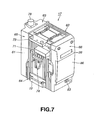
- FIG.7 shows a perspective view of the encoding/transmission unit 17.
- the encoding/transmission unit 17 is substantially of a rectangular solid.
- a surface to which the main body unit 16 is attached is a front surface 61
- a surface, which is the opposite of the front surface 61, to which the battery unit 18 is attached is a rear surface 62.
- a surface which faces upward when the main body unit 16 is attached to the encoding/transmission unit 17 is a top surface 63
- a surface which faces downward is a bottom surface 64.
- a surface which is located at the left side of the front surface 61 when viewed from the front surface 61 side is a left surface 65
- a surface which is located at the right side of the front surface 61 is a right surface 66.
- FIG.8 shows a plan view of the encoding/transmission unit 17 viewed from the front surface 61 side.
- the front surface 61 is provided with a connector unit 71 for making a connection with the main body unit 16, which has a connector 71a of, for example, 40 pins.
- the connector 71a is connected to a connection terminal of the main body unit 16.
- the connector 71a receives baseband digital video signals and baseband digital audio signals etc. from the main body unit 16.
- the front surface 61 is provided with a main body side power supply output connector 72. DC power is supplied to the main body unit 16 via the main body power supply output connector 72.
- the front surface 61 is provided with joint mechanisms 73, 74.
- the main body unit 16 and the encoding/transmission unit 17 are mechanically connected to each other by the joint mechanisms 73, 74.
- FIG.9 shows a plan view of the encoding/transmission unit 17 viewed from the rear surface 62 side.
- the rear surface 62 is provided with a battery side power supply input connector 76. DC power is supplied to the encoding/transmission unit 17 from the battery unit 18 via the battery side power supply input connector 76.
- the rear surface 62 is provided with a joint mechanism 77. The encoding/transmission unit 17 and the battery unit 18 are mechanically connected to each other by the joint mechanisms 77.
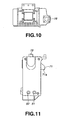
- FIG.10 shows a plan view of the encoding/transmission unit 17 viewed from the top surface 63 side.
- the top surface 63 is provided with an N connector 78 for making a connection with an antenna.
- the transmission antenna 19 is removably connected to the N connector 78.
- the bottom surface 64 is provided with an external power supply input terminal 79 to which DC power is supplied from an external DC power supply, and an external power supply output terminal 80 which supplies DC power to an external device.
- FIG.11 shows a plan view of the encoding/transmission unit 17 viewed from the left surface 65 side.
- the left surface 65 is provided with coaxial connectors 81, 82 for outputting transport streams.
- FIG.12 and FIG.13 show plan views of the encoding/transmission unit 17 viewed from the right surface 66 side.
- the right surface 66 is provided with a power switch 83 and a display unit 26.
- the right surface 66 is provided with an operation input unit 25 which is used by the user in performing various set up for the wireless camera 11.
- the operation input unit 25 is covered by a panel cover 86 for preventing mis-operation when shooting a subject. The user can use the operation input unit 25 by sliding the panel cover 86 downward.
- the operation input unit 25 is provided with a cross-shaped cursor button 91 for moving set up items, a menu button 92 for changing set up menus, an enter button 93 for registering set up, and a back-light switch for turning on a back-light of the display unit 26.
- the user can perform various set up for the wireless camera 11 by confirming the contents displayed on the display unit 26 and operating the operation input unit 25.
- parameter set up items As the parameter set up items which are set up by the operation input unit 25, there are generally parameter set up for RF signals, parameter set up for baseband signals, and parameter set up for encoding transport streams. These parameter set up items are displayed on the display unit 26 in the form of a directory structure, as shown in FIG.14. Specifically, at first, a menu window 95 as a menu screen is displayed. Then the screen can be moved to detailed parameter set up screens of respective parameter set up items by selecting an RF setting window 96 as a parameter set up screen for RF signals, a BB setting window 97 as a parameter set up screen for baseband signals, or an ENC setting window 98 as a parameter set up screen for encoding transport streams, from the menu window 95.
- RF center freq RF signals center frequency
- RF emit power set up for RF signals emitting power
- RF emission control set up for RF signals emission control
- RF emission confirm RF signals emission confirmation
- RF center freq a center frequency of from 2,400 to 2,700 MHz can be selected.
- power of three stages of High, Middle, or Low can be selected.
- OFDM, CW, or OFF can be selected.
- the set up items for baseband signals of the BB setting window 97 there are set up for digital modulation manner of baseband signals (Constellation), set up for transmission code rate (Code rate), set up for guard interval length of OFDM modulation (Guard interval), and set up for time interleave amount at the time of transmission-line-encoding (Time interleave).
- Constellation as a digital orthogonal modulation manner, 64 QAM, 16 QAM, or QPSK can be selected.
- 64 QAM, 16 QAM, or QPSK can be selected.
- 64 QAM, 16 QAM, or QPSK can be selected.
- In performing set up for Code rate as a code rate, 7/8, 5/6, 3/4, 2/3, or 1/2 can be selected.
- In performing set up for Guard interval as a guard interval length, 1/32, 1/16, 1/8, or 1/4 can be selected.
- Time interleave as a delay amount of time interleave, four stages of Fast (largest delay amount), Run, Walk, or Off
- Profile and level As the set up items for encoding transport streams of the ENC setting window 98, there are set up for profile and level (Profile & level), set up for video signals coded rate (Coded video rate), set up for audio layer (Audio layer), set up for first audio signals component mode (Audio comp. mode ch 1/2), set up for second audio signals component mode (Audio comp.
- mode ch 3/4 set up for first audio signals coded rate (Coded audio rate ch 1/2), set up for second audio signals coded rate(Coded audio rate ch 3/4), set up for transport streams coded rate (TS rate), set up for PID of TS packets including video signals (PID video), set up for PID of TS packets including first audio signals (PID audio ch 1/2), set up for PID of TS packets including PMT (PID PMT), set up for PID of TS packets of PCR (PID PCR), set up for 1 packet byte length (TS byte length), and set up for transport streams transmission mode (TS Stream mode).
- profile and level is set up and fixed at MP@ML.
- a coded rate of from 1,500 to 15,000 kbps can be selected.
- compression mode of MPEG 1 audio layer 1 or MPEG 1 audio layer 2 can be selected.
- Audio comp. mode ch 1/2 as the contents of a first audio signal component, Stereo, Dual, or Off can be selected.
- Audio comp. mode ch 3/4 as the contents of a second audio signal component, Stereo, Dual, or Off can be selected.
- a coded rate of from 32 to 448 kbps can be selected.
- a coded rate of from 32 to 448 kbps can be selected.
- a coded rate of transport streams of from 2,500 to 17,000 kbps can be selected.
- a byte length of 188 bytes or 204 bytes can be selected.
- packet transmission or burst transmission can be selected.
- the reception relay station 12 includes the external reception unit 13, the internal reception unit 14, and the plural IF cables 15 which connects the external reception unit 13 and the internal reception unit 14.
- the external reception unit 13 includes a reception antenna 100, a high-frequency amplifier 101, and a frequency converter 102.
- the internal reception unit 14 includes an OFDM demodulation/transmission-line-decoding circuit 103, and a TS output unit 104.
- the reception antenna 100 receives transmission waves transmitted from the wireless camera 11, and send thus received RF signals to the high-frequency amplifier 101.
- the high-frequency amplifier 101 high-frequency-amplifies RF signals received by the reception antenna 100, and high-frequency-amplified RF signals are sent to the frequency converter 102.
- the frequency converter 102 down-converts carrier frequency of high-frequency-amplified RF signals to generate IF signals.
- the external reception unit 13 receives transmission waves transmitted from the wireless camera 11 using the reception antenna 100, and frequency-converts received RF signals to IF signals of an intermediate frequency band.
- IF signals output from the external reception unit 13 is supplied to the OFDM demodulation/transmission-line-decoding circuit 103 in the internal reception unit 14 via the IF cables 15.
- the OFDM demodulation/transmission-line-decoding circuit 103 performs channel selection and orthogonal demodulation for received IF signals. Also, the OFDMdemodulation/transmission-line-decoding circuit 103 performs synchronization processing such as FFT window synchronization and symbol timing synchronization, while concurrently performing OFDM demodulation such as orthogonal transformation for performing FFT (Fast Fourier Transform) processing every effective symbol to generate frequency-domain OFDM signals, waveform equalization, and demapping to demodulate transmission data. Furthermore, the OFDM demodulation/transmission-line-decoding circuit 103 performs transmission-line-decoding for demodulated transmission data such as symbol deinterleaving, bit . deinterleaving, inner code decoding, convolutional deinterleaving, and RS decoding, to decode transport streams. Decoded transport streams are sent to the TS output unit 104.
- synchronization processing such as FFT window synchronization and symbol timing synchronization
- OFDM demodulation such as
- the TS output unit 104 performs smoothing for transport streams sent from the OFDM demodulation/transmission-line-decoding circuit 103.
- the internal reception unit 14 performs channel selection for selecting predetermined frequency from received IF signals, and OFDM demodulation/transmission-line-decoding, to decode transport streams transmitted from the wireless camera 11.
- Transport streams output from the internal reception unit 14 are transmitted to a broadcasting station, and information thereof is processed and delivered to viewers.
- the OFDM demodulation/transmission-line-decoding circuit 103 includes an A/D converter 111, a digital orthogonal demodulation circuit 112, an FFT operation circuit 113, a narrow-band fc error calculation (FAFC) circuit 114, a broad-band fc error calculation (WAFC) circuit 115, a numeric control oscillation (NCO) circuit 116, an equalizer 117, a demapping circuit 118, a Transmission Parameter Signaling (TPS) demodulation circuit 119, a bit/symbol deinterleaving circuit 120, a viterbi decoding circuit 121, a convolutional deinterleaving circuit 122, a reed solomon decoding circuit 123, and a MUX adaptation/energy inverse diffusion circuit 124.
- A/D converter 111 the OFDM demodulation/transmission-line-decoding circuit 103
- FFT operation circuit 113 FFT operation circuit 113
- FAFC narrow-band fc error calculation
- IF signals supplied from the external reception unit 13 via the IF cables 15 are sent to the A/D converter 111.
- the A/D converter 111 digitizes IF signals. Digitized IF signals are sent to the digital orthogonal demodulation circuit 112. The A/D converter 111 performs quantization using double clock such that effective symbol and guard interval of OFDM time-domain signals are sampled by 4,096 samples and 1,024 samples, respectively.
- the digital orthogonal demodulation circuit 112 performs orthogonal demodulation for digitized IF signals using a carrier signal of a predetermined frequency (carrier frequency) to generate baseband OFDM signals.
- Baseband OFDM signals sent from the digital orthogonal demodulation circuit 112 are time-domain signals before being processed under FFT operation. So, baseband signals to be processed by FFT operation, which have been processed under digital orthogonal demodulation are referred to as OFDM time-domain signals, hereinafter.
- the OFDM time-domain signals become complex signals having real axis components (I channel signals) and imaginary axis components (Q channel signals) after being processed under orthogonal demodulation.
- the OFDM time-domain signals sent from the digital orthogonal demodulation circuit 112 are sent to the FFT operation circuit 113 and the narrow-band fc error calculation circuit 114.
- the FFT operation circuit 113 performs FFT operation for the OFDM time-domain signals, and extracts and outputs data which is orthogonal-modulated to respective subcarriers.
- Signals sent from the FFT operation circuit 113 are frequency-domain signals after being processed under FFT operation. So, signals which have been processed under FFT operation are referred to as OFDM frequency-domain signals, hereinafter.
- the FFT operation circuit 113 extracts signals in the range of effective symbol length of such as 2,048 samples from one OFDM symbol, or excludes signals in the range of guard interval from one OFDM symbol, and performs FFT operation for extracted 2048-sample OFDM time-domain signals. Specifically, the start point of the operation is between the boundary of OFDM symbol and the end of guard interval.
- the operation range is referred to as FFT window.
- the OFDM frequency-domain signals sent from the FFT operation circuit 113 become, similar to the OFDM time-domain signals, complex signals havingreal axis components (I channel signals) and imaginary axis components (Q channel signals).
- the OFDM frequency-domain signals are sent to the broad-band fc error calculation circuit 115 and the equalizer 117.
- the narrow-band fc error calculation circuit 114 calculates carrier frequency error included in the OFDM time-domain signals. Specifically, the narrow-band fc error calculation circuit 114 calculates narrow-band carrier frequency error with precision of under ⁇ 1/2 of frequency interval of subcarriers. Carrier frequency error is center frequency position error of the OFDM time-domain signals, which is generated due to gap of reference frequency output from a local oscillator of the frequency converter 102, and error ratio of output data is enlarged as the carrier frequency error increases. Narrow-band carrier frequency error obtained by the narrow-band fc error calculation circuit 114 is sent to the NCO circuit 116.
- the broad-band fc error calculation circuit 115 calculates carrier frequency error included in the OFDMtime-domain signals. Specifically, the broad-band fc error calculation circuit 115 calculates broad-band carrier frequency error with precision of frequency interval of subcarriers. The broad-band fc error calculation circuit 115 obtains a shift amount by referring to a continual pilot signal (CP signal) and calculates the shift degree of the CP signal from the original insertion point thereof. Broad-band carrier frequency error obtained by the broad-band fc error calculation circuit 115 is sent to the NCO circuit 116.
- CP signal continual pilot signal
- the NCO circuit 116 sums up narrow-band carrier frequency error with precision of under ⁇ 1/2 of frequency interval of subcarriers calculated by the narrow-band fc error calculation circuit 114 and broad-band carrier frequency error with precision of frequency interval of subcarriers calculated by the broad-band fc error calculation circuit 115, and generates carrier frequency error correction signals, which frequency increases and decreases in accordance with summed up carrier frequency error.
- the carrier frequency error correction signals are complex signals, and are sent to the digital orthogonal demodulation circuit 112.
- the carrier frequency error correction signals correct carrier frequency fc based on the carrier frequency error correction signals, while performing digital orthogonal demodulation.
- the equalizer 117 performs phase equalization and amplitude equalization for the OFDM frequency-domain signals using a scattered pilot signal (SP signal).
- SP signal scattered pilot signal
- the OFDM frequency-domain signals which have been processed under phase equalization and amplitude equalization are sent to the demapping circuit 118 and the TPS demodulation circuit 119.
- the TPS demodulation circuit 119 separates TPS signals allocated to predetermined frequency component, and demodulate information of code rate, modulation manner, and guard interval length from the separated TPS signals.
- the demapping circuit 118 performs demapping for the OFDM frequency-domain signals which have been processed under phase equalization and amplitude equalization by the equalizer 117 in accordance with the modulation manner thereof. Data which has been processed under demapping is sent to the bit/symbol deinterleaving circuit 120.
- the bit/symbol deinterleaving circuit 120 performs the opposite processing of bit interleaving and symbol interleaving which are performed at the transmission-line-encoding/OFDM modulation circuit 44. Data which has been processed under bit deinterleaving and symbol deinterleaving is sent to the viterbi decoding circuit 121.
- the viterbi decoding circuit 121 performs maximum likelihood decoding using viterbi algorithm. Data which has been processed under maximum likelihood decoding is sent to the convolutional deinterleaving circuit 122.
- the convolutional deinterleaving circuit 122 performs the opposite processing of convolutional interleaving which is performed at the transmission-line-encoding/OFDM modulation circuit 44. Data which has been processed under convolutional deinterleaving is sent to the reed solomon decoding circuit 123.
- the reed solomon decoding circuit 123 performs reed solomon decoding based on parity of 16 bytes which is added to input data series at the transmission-line-encoding/OFDM modulation circuit 44, and corrects error if error is detected. Data which has been processed under reed solomon decoding is sent to the MUX adaptation/energy inverse diffusion circuit 124.
- the MUX adaptation/energy inverse diffusion circuit 124 keep synchronization byte of leading 1 byte of TS packets intact in case the synchronization byte is 47h, while, in case the synchronization byte is B8h, performing bit inversion to correct the synchronization byte from B8h to 47h.
- the MUX adaptation/energy inverse diffusion circuit 124 simultaneously initializes a shift-register for generating pseudorandom binary sequence (PRBS) which is used in performing energy diffusion every TS packet whose synchronization byte is B8h by predetermined seed value.
- PRBS pseudorandom binary sequence
- the PRBS series is (x 15 + x 14 + 1), and seed value is 009Ah.
- the MUX adaptation/energy inverse diffusion circuit 124 performs energy inverse diffusion by operating exclusive OR of data of TS packets excluding synchronization byte (1 byte) and PRBS. Data series which have been processed under energy inverse diffusion are sent to the TS output unit 104 as transport streams.
- radio relay system 1 can be applied to such as a golf relaying, marathon relaying, concert relaying, stadium relaying of soccer, baseball, athletic sports, etc., interview relaying of news, monitoring of a fire station or police station, school broadcasting, and security management.
- the wireless camera 11 can be used as a player camera, multi-camera, or gallery camera. Also, in case of applying the radio relay system 1 to a marathon relaying, the wireless camera 11 can be used as a motorcycle camera, relay car camera, or roadside camera. Also, in case of applying the radio relay system 1 to a concert relaying, the wireless camera 11 can be used as a live video camera, or audience camera. Also, In case of applying the radio relay system 1 to a stadium relaying, the wireless camera 11 can be used as a camera for ground level shooting. Also, In case of applying the radio relay system 1 to an interview relaying of news, the wireless camera 11 can be used as a camera for use in the place where cables cannot be arranged. Also, in case of applying the radio relay system 1 to monitoring of a fire station or police station, since real time transmission becomes possible, immediacy or instancy can be achieved.
- the radio relay system 1 has the pick up unit 21, the video encoding circuit 37, the transmission-line-encoding/OFDM modulation circuit 44, the transmission unit 24, and the battery unit 18 housed in a housing or a unitable housing.
- the wireless camera 11 can be operated by one operator without the need of help of an assistant.
- the wireless camera according to the present invention has the pick up means, the encoding means, the modulation means for performing orthogonal frequency-division-multiplex modulation, the transmission means, and the antenna housed in a housing or a unitable housing.
- the wireless camera according to the present invention can be operated by one operator.
Landscapes
- Engineering & Computer Science (AREA)
- Signal Processing (AREA)
- Multimedia (AREA)
- Computer Networks & Wireless Communication (AREA)
- Two-Way Televisions, Distribution Of Moving Picture Or The Like (AREA)
- Television Systems (AREA)
Abstract
A wireless camera 11 includes a main body unit 16, encoding/transmission unit 17, and a battery unit 18. The encoding/transmission unit 17 includes a encoding/modulation unit 23 for performing MPEG 2 encoding and OFDM modulation, frequency converter 27, high-frequency amplifier 28, and a transmission antenna 19. The main body unit 16, encoding/transmission unit 17, and battery unit 18 are unitedly configured. <IMAGE>
Description
The present invention relates to a wireless camera for use in a relaying from the
spot for television broadcasting.
Conventionally, wireless cameras have been used to perform a relaying from the
spot for television broadcasting such as news programs, sports programs, and various
event programs. When such a wireless camera is used, video signals and audio signals
picked up and gathered by the wireless camera are transmitted to a base relay station
such as a relay car using ground waves employing radio transmission. Thus, when
such a wireless camera is used, since it is not necessary to take time to arrange and
remove cables, less labor is required as compared with a conventional camera which
is connected to cables. Also, since the camera angle is spread and degree of freedom
is increased, the mobility of a wireless camera is improved at the spot where a relaying
for television broadcasting is performed.
Recently, in transmitting video signals and audio signals obtained by such a
wireless camera, video signals and audio signals are digitized and modulated in the
digital modulation manner.
On the other hand, in a relay system employing such a wireless camera, it is
difficult to secure transmission quality under the fading environment caused by
movement and multipath. So, it is necessary to secure a transmission path all the time
in shooting a subject by making an assistant, other than an operator of a wireless
camera body, operate transmitting apparatuses such as a transmitter and a transmission
antenna which are separated from the wireless camera body.
Accordingly, the present invention has an object to overcome the above-mentioned
drawbacks of the prior art by providing a wireless camera which can be
operated by single operator with its mobility desirably secured.
The above object can be attained by providing a wireless camera, including pick
up means, encoding means for encoding video signals picked up by the pick up means
to generate transmission data of a predetermined encoding system, modulation means
for orthogonal frequency-division-multiplex modulating the transmission data encoded
by the encoding means, and transmission means for frequency-converting modulated
signals generated by the modulation means into signals of a radio frequency band, and
radiating frequency-converted signals via an antenna, wherein the pick up means, the
encoding means, the modulation means, and the transmission means are housed in a
housing or a unitable housing.
The wireless camera has the pick up means, the encoding means, the
modulation means for performing orthogonal frequency-division-multiplex
modulation, the transmission means, and the antenna housed in a housing or a unitable
housing.
A ground digital radio relay system (referred to as a radio relay system,
hereinafter) to perform a relaying from the spot for television broadcasting such as
news programs, sports programs, and various event programs will further be described
below concerning the best modes for carrying out the present invention with reference
to the accompanying drawings.
Fig. 1 shows the configuration of a radio relay system 1 according to the present
invention.
As shown in FIG.1, the radio relay system 1 includes a wireless camera 11 for
shooting a subject, a reception relay station 12 for receiving transmission signals from
the wireless camera 11. The reception relay station 12 includes an external reception
unit 13, an internal reception unit 14, and a plurality of IF cables 15 which connects
the external reception unit 13 and the internal reception unit 14.
The radio relay system 1 is used to perform a relaying from the spot for
television broadcasting such as news programs, sports programs, and various event
programs, and is a system adapted for transmitting video signals etc. of a video subject
shot by the wireless camera 11 to the reception relay station 12 using ground waves
employing radio transmission. In the radio relay system 1, the camera angle and
shooting position are not restrained by cables etc. which connect the wireless camera
11 and the reception relay station 12. Also, the mobility of the wireless camera 11 is
improved at the spot where a relaying for television broadcasting is performed.
In the radio relay system 1, transport streams conforming to the MPEG 2
Systems are employed as radio transmission signals from the wireless camera 11 to the
reception relay station 12, and the OFDM (Orthogonal Frequency Division Multiplex)
modulation manner is employed as a modulation manner. By generating and
transmitting digitized transport streams from a video subject, it becomes possible to
transmit video signals and audio signals of high quality with less S/N ratio
deterioration as compared with the case in which signals of a video subject are
transmitted in an analog manner. Also, when the OFDM modulation manner is
employed, image deterioration caused by variation of electric field intensity due to
reception in the moving state can be suppressed, and influence caused by multipath
disturbance can also be suppressed. So, by employing the OFDM modulation manner,
video signals and audio signals can be transmitted with high quality.
Next, the wireless camera 11 will be explained in detail.
FIG.2 and FIG.3 show schematic views of the wireless camera 11, while FIG.4
shows a block diagram of the wireless camera 11.
As shown in FIG.2, the wireless camera 11 includes a main body unit 16
provided with a pick up unit etc., an encoding/transmission unit 17 attached to the
main body unit 16, and a battery unit 18 attached to the encoding/transmission unit 17.
As shown in FIG.3, the encoding/transmission unit 17 is removably attached to the
main body unit 16, and the battery unit 18 is also removably attached to the
encoding/transmission unit 17.
When the encoding/transmission unit 17 is attached to the main body unit 16,
the encoding/transmission unit 17 is electrically connected to the main body unit 16.
When the battery unit 18 is attached to the encoding/transmission unit 17, the main
body unit 16 and the encoding/transmission unit 17 can be supplied with electric
power by the battery unit 18. Also, the encoding/transmission unit 17 is provided with
a transmission antenna 19. The transmission antenna 19 transmits video signals etc.
picked up by the wireless camera 11 by employing radio transmission. The
transmission antenna 19 is a non-directional antenna.
As shown in FIG.4, the main body unit 16 includes a pick up unit 21 and a
microphone 22.
The pick up unit 21 is composed of a pick up optical system, a CCD image
sensor, an A/D converter, a camera signal processing unit, etc. The pick up unit 21
performs analog-to-digital conversion and timing processing for video signals picked
up and converted to electric signals by the CCD image sensor to generate baseband
digital video signals. The pick up unit 21 sends thus picked up and processed
baseband digital video signals and synchronization signals of the digital video signals
to the encoding/transmission unit 17.
The microphone 22 gathers audio speech or sound at respective relay spots, and
digitize gathered audio signals to generate baseband digital audio signals. The
microphone 22 sends thus gathered and processed baseband digital audio signals to the
encoding/transmission unit 17.
The encoding/transmission unit 17 includes the transmission antenna 19, an
encoding/modulation unit 23, a transmission unit 24, an operation input unit 25 which
is operated by the user to perform input processing, a display unit 26 for displaying set
up information etc. to the user. The transmission unit 24 in the encoding/transmission
unit 17 includes a frequency converter 27 and a high-frequency amplifier 28.
The encoding/modulation unit 23 receives baseband digital video signals and
baseband digital audio signals from the main body unit 16. Also, the
encoding/modulation unit 23 receives predetermined data signals from the main body
unit 16. The encoding/modulation unit 23 compresses and encodes digital video
signals and digital audio signals based on the MPEG 2 Systems. Then, the
encoding/modulation unit 23 multiplexes respective compressed data, other control
data, etc. to generate transport streams conforming to the MPEG 2 Systems.
Furthermore, the encoding/modulation unit 23 performs predetermined
transmission-line-encoding or OFDM frame construction for generated transport
streams such as energy diffusion, RS encoding, convolutional interleaving, inner code
encoding, bit interleaving, symbol interleaving, mapping corresponding to modulation
manner, and insertion of predetermined pilot signals and null signals. Also, the
encoding/modulation unit 23 performs OFDM modulation for transmission-line-encoded
data streams such as orthogonal transformation for making 2,048 I, Q signals
one symbol and performing IFFT (Inverse Fast Fourier Transform) operation to
generate time-domain OFDM signals, guard interval addition for adding guard interval
to time-domain OFDM signals by copying and pasting the latter half of one effective
symbol to the first half thereof, orthogonal modulation for orthogonal-modulating
time-domain OFDM signals to which guard interval is added to generate IF signals of
an intermediate frequency band. Thus, the encoding/modulation unit 23 generates IF
signals of an intermediate frequency band by performing the transmission-line-encoding
and the OFDM modulation. The IF signals output from the
encoding/modulation unit 23 is sent to the frequency converter 27 in the transmission
unit 24.
The frequency converter 27 in the transmission unit 24 up-converts carrier
frequency of IF signals to generate RF signals for radio transmission. Then, RF
signals are sent to the high-frequency amplifier 28 in the transmission unit 24.
The high-frequency amplifier 28 in the transmission unit 24 high-frequency-amplifies
RF signals, and the transmission antenna 19 radiates amplified RF signals.
Then, radio transmission signals from the wireless camera 11 are transmitted
to the reception relay station 12.
As described above, the wireless camera 11 can transmit video signals of a
video subject to the reception relay station 12 using ground waves employing radio
transmission by encoding picked up signals of a video subject, generating transport
streams, and then performing OFDM modulation for generated transport streams.
Next, referring to FIG.5, internal circuit configuration of the
encoding/modulation unit 23 in the encoding/transmission unit 17 will be explained
in detail.
As shown in FIG.5, the encoding/modulation unit 23 includes a CPU 31, a
camera connector I/F (Interface) 32, a delay circuit 33, a VITC (Vertical Interface
Time Code) circuit 34, a pre-filtering circuit 35, an encoder I/F circuit 36, a video
encoding circuit 37, a first audio encoding circuit 38, a second audio encoding circuit
39, a first FIFO (First In First Out) circuit 40, a second FIFO circuit 41, a buffer circuit
42, an MUX (Multiplex) circuit 43, a transmission-line-encoding/OFDMmodulation
circuit 44, a transmission analog processing circuit 45, a TS output processing circuit
46, a RAM (Random Access Memory) 47, and a flush memory 48.
The CPU 31 is connected to the delay circuit 33, VITC circuit 34, pre-filtering
circuit 35, encoder I/F circuit 36, video encoding circuit 37, first audio encoding circuit
38, second audio encoding circuit 39, MUX circuit 43 and transmission-line-encoding/OFDM
modulation circuit 44, via a bus 30. The CPU 31 performs set up of
various parameters and operation controlling for these respective circuits via the bus
30. Also, the CPU 31 is connected to the operation input unit 25 via the bus 30, and
receives operation input information from the operation input unit 25 to perform set
up of respective circuits in accordance with the operation input information. Also, the
CPU 31 is connected to the display unit 26 via the bus 30, and performs controlling
for displaying current set up contents of respective circuits. Also, the CPU 31 is
connected to the RAM 47 and flush memory 48 via the bus 30. The RAM 47 is a
volatile memory, in which data processed by the CPU 31 is stored. The flush memory
48 is a nonvolatile memory, in which parameters which are required to be preserved
after a power switch is turned off is stored.
The camera connector I/F (Interface) 32 is an interface for making a connection
with the main body unit 16. The encoding/modulation unit 23 receives baseband
digital video signals (Video), synchronization signals thereof (HD/VD), and baseband
digital audio signals (Audio), from the main body unit 16 via the camera connector I/F
(Interface) 32. The encoding/modulation unit 23 can receive audio signals of four
channels from the main body unit 16. When the audio signals of four channels from
the main body unit 16 are received, audio signals of two channels are multiplexed and
sent in the form of one audio stream. That is, the encoding/modulation unit 23
receives two audio streams from the main body unit 16. An audio stream including
audio signals of channel 1 and those of channel 2 is referred to as first audio signals
(Audio ch 1/2), while an audio stream including audio signals of channel 3 and those
of channel 4 is referred to as second audio signals (Audio ch 3/4).
The baseband digital video signals (Video) from the main body unit 16 are sent
to the delay circuit 33. Also, the synchronization signals of the digital video signals
(HD/VD) are sent to the VITC circuit 34. The first and second audio signals (Audio
ch 1/2, ch 3/4) from the main body unit 16 are sent to the encoder I/F circuit 36.
The delay circuit 33 delays the input baseband digital video signals by
predetermined period. The baseband digital video signals delayed by the delay circuit
33 are sent to the VITC circuit 34.
The VITC circuit 34 extracts time code information included in the baseband
digital video signals. The extracted time code information is sent to the CPU 31, and
is used when time stamp for MPEG encoding processing is generated. The baseband
digital video signals (Video), from which the time code information is extracted, and
the synchronization signals of the digital video signals (HD/VD) are sent to the pre-filtering
circuit 35.
The pre-filtering circuit 35 performs band limitation for video signals. The
baseband digital video signals (Video) and the synchronization signals of the digital
video signals (HD/VD) which have been processed under the band limitation of the
pre-filtering circuit 35 are sent to the encoder I/F circuit 36.
The encoder I/F circuit 36 performs pre-processing of MPEG encoding such as
adjustment of angle of view and audio encoding for the baseband digital video signals
(Video) and the first and second audio signals (Audio ch 1/2, ch 3/4). The baseband
digital video signals (Video) which are pre-processed by the encoder I/F circuit 36 are
sent to the video encoding circuit 37. The first audio signals (Audio ch 1/2) which are
pre-processed by the encoder I/F circuit 36 are sent to the first audio encoding circuit
38, while the second audio signals (Audio ch 3/4) which are pre-processed by the
encoder I/F circuit 36 are sent to the second audio encoding circuit 39.
The video encoding circuit 37 performs video compression and encoding for the
baseband digital video signals based on the MPEG 2 Systems. Video signals (video
elementary stream (V_ES)) which are compressed and encoded by the video encoding
circuit 37 are resent to the encoder I/F circuit 36, and are then sent to and stored in the
buffer circuit 42 after passing through the encoder I/F circuit 36.
The first audio encoding circuit 38 performs audio compression and encoding
for the first baseband digital audio signals based on the MPEG Systems. Audio signals
(first audio elementary stream (A_ES 1/2)) which are compressed and encoded by the
first audio encoding circuit 38 are sent to the first FIFO circuit 40, where data thereof
is temporary delayed, and are then sent to and stored in the buffer circuit 42.
The second audio encoding circuit 39 performs audio compression and
encoding for the second baseband digital audio signals based on the MPEG Systems.
Audio signals (second audio elementary stream (A_ES 3/4)) which are compressed and
encoded by the second audio encoding circuit 39 are sent to the second FIFO circuit
41, where data thereof is temporary delayed, and are then sent to and stored in the
buffer circuit 42.
The MUX circuit 43 reads out the video elementary stream (V_ES) and the first
and second audio elementary streams (A_ES 1/2, A_ES 3/4) from the buffer circuit 42,
and packets data of these elementary streams to generate TS packets each being data
unit. The MUX circuit 43 multiplexes the three elementary streams with the packet
unit to generate transport streams conforming to the MPEG 2 Systems. Also, the
MUX circuit 43 generates TS packets including transmission control information
based on information supplied from the CPU 31 if necessary, and multiplexes the TS
packets into the transport streams. Transport streams generated by the MUX circuit
43 are sent to the transmission-line-encoding/OFDM modulation circuit 44 or the TS
output processing circuit 46.
The transmission-line-encoding/OFDM modulation circuit 44 performs
transmission-line-encoding and OFDM modulation for input transport streams to
generate IF signals. IF signals generated by the transmission-line-encoding/OFDM
modulation circuit 44 is sent to the transmission analog processing circuit 45.
The transmission analog processing circuit 45 performs filtering and analog
matching for input transmission-line-encoded and OFDM-modulated data streams sent
from the transmission-line-encoding/OFDM modulation circuit 44. IF signals which
are analog-processed by the transmission analog processing circuit 45 are sent to the
frequency converter 27 in the transmission unit 24 via a coaxial cable, etc.
The TS output processing circuit 46 performs pull-up processing of power
supply voltage for input transport streams sent from the MUX circuit 43 to generate
transport streams conforming to the specification of the serial transmission format.
Transport streams which have been processed under the pull-up processing of power
supply voltage by the TS output processing circuit 46 are sent to the outside of the
wireless camera 11 via a coaxial cable, etc. The TS output processing circuit 46 is an
optional circuit which is used in transmitting picked up signals of the wireless camera
11 without employing radio broadcasting but employing wire broadcasting.
Next, referring to FIG.6, configuration of the transmission-line-encoding/OFDM
modulation circuit 44 in the encoding/modulation unit 23 will be
explained in detail.
As shown in FIG.6, the transmission-line-encoding/OFDM modulation circuit
44 includes an MUX adaptation/energy diffusion circuit 50, a reed solomon encoder
51, a convolutional interleaving circuit 52, a convolutional encoder 53, a bit/symbol
interleaving circuit 54, a mapping circuit 55, a frame adaptation circuit 56, an IFFT
circuit 57, a guard interval addition circuit 58, a D/A converter 59, and a TPS
generation circuit 60.
The transmission-line-encoding/OFDM modulation circuit 44 receives transport
streams from the MUX circuit 43 arranged upstream thereof . Thus received transport
streams are sent to the MUX adaptation/energy diffusion circuit 50 of the
transmission-line-encoding/OFDM modulation circuit 44.
The MUX adaptation/energy diffusion circuit 50 performs bit inversion for
synchronization byte of leading 1 byte of TS packets every 8 TS packets to correct the
synchronization byte from 47h to B8h. At this time, the MUX adaptation/energy
diffusion circuit 50 simultaneously initializes a shift-register for generating
pseudorandom binary sequence (PRBS) which is used in performing energy diffusion
every 8 TS packets by predetermined seed value (initial value). For example, the
PRBS series is (x15 + x14 + 1), and seed value is 009Ah. The MUX adaptation/energy
diffusion circuit 50 performs energy diffusion by operating exclusive OR of data of TS
packets excluding synchronization byte (1 byte) and PRBS. Data series which have
been processed under energy diffusion are sent to the reed solomon encoder 51.
The reed solomon encoder 51 performs reed solomon encoding for input data
series, and adds parity of 16 bytes thereto every TS packet. Data series to which parity
is added are sent to the convolutional interleaving circuit 52.
The convolutional interleaving circuit 52 performs convolutional interleaving
for input data series. Data series which have been processed under convolutional
interleaving are sent to the convolutional encoder 53.
The convolutional encoder 53 performs convolutional encoding using two
encoders which are of G1 = 171 (Octal) and of G2 = 133 (Octal), and performs 2-bit
encoding for 1-bit input data. In case punctured processing is performed, 2-bit output
encoded data is punctured. Data series which have been processed under
convolutional encoding are sent to the bit/symbol interleaving circuit 54.
The bit/symbol interleaving circuit 54 performs interleaving for frequency in
OFDM symbol and performs interleaving for bits to be allocated to mapping points.
Data series which have been processed under interleaving are sent to the mapping
circuit 55.
The mapping circuit 55 divides data series on the basis of code length
corresponding to modulation manner (for example, 6-bit code length in case of 64
QAM), and adds divided data series to predetermined mapping points. By thus
allocating data series to mapping points, two-dimensional information composed of
I, Q components is output. Data series of two-dimensional information are sent to the
frame adaptation circuit 56.
The frame adaptation circuit 56 inserts predetermined pilot signals, transmission
parameter signaling (TPS), and null signals sent from the TPS generation circuit 60
into mapped data series of two-dimensional information, or perform OFDM frame
construction. Data series which have been processed under OFDM frame construction
are sent to the IFFT circuit 57.
The IFFT circuit 57 makes 2,048I, Q signals one OFDM symbol, and performs
IFFT operation in one lot. Data series which have been processed under IFFT
operation are sent to the guard interval addition circuit 58 every one effective symbol.
The guard interval addition circuit 58 adds guard interval to effective symbol
by copying and pasting the latter quarter signal wave of one effective symbol output
from the IFFT circuit 57 to the leading portion thereof. Data series to which guard
interval is added are sent to the D/A converter 59.
The D/A converter 59 converts digital signals to analog signals, and outputs the
converted signals as OFDM-modulated signals.
Thus generated OFDM-modulated signals are sent to the transmission analog
processing circuit 45.
Next, configuration of the encoding/transmission unit 17 will be explained in
detail.
FIG.7 shows a perspective view of the encoding/transmission unit 17.
As shown, the encoding/transmission unit 17 is substantially of a rectangular
solid. Of respective surfaces of the encoding/transmission unit 17, a surface to which
the main body unit 16 is attached is a front surface 61, while a surface, which is the
opposite of the front surface 61, to which the battery unit 18 is attached is a rear
surface 62. A surface which faces upward when the main body unit 16 is attached to
the encoding/transmission unit 17 is a top surface 63, while a surface which faces
downward is a bottom surface 64. A surface which is located at the left side of the
front surface 61 when viewed from the front surface 61 side is a left surface 65, while
a surface which is located at the right side of the front surface 61 is a right surface 66.
FIG.8 shows a plan view of the encoding/transmission unit 17 viewed from the
front surface 61 side. The front surface 61 is provided with a connector unit 71 for
making a connection with the main body unit 16, which has a connector 71a of, for
example, 40 pins. The connector 71a is connected to a connection terminal of the
main body unit 16. The connector 71a receives baseband digital video signals and
baseband digital audio signals etc. from the main body unit 16. Also, the front surface
61 is provided with a main body side power supply output connector 72. DC power
is supplied to the main body unit 16 via the main body power supply output connector
72. Also, the front surface 61 is provided with joint mechanisms 73, 74. The main
body unit 16 and the encoding/transmission unit 17 are mechanically connected to
each other by the joint mechanisms 73, 74.
FIG.9 shows a plan view of the encoding/transmission unit 17 viewed from the
rear surface 62 side. The rear surface 62 is provided with a battery side power supply
input connector 76. DC power is supplied to the encoding/transmission unit 17 from
the battery unit 18 via the battery side power supply input connector 76. Also, the
rear surface 62 is provided with a joint mechanism 77. The encoding/transmission unit
17 and the battery unit 18 are mechanically connected to each other by the joint
mechanisms 77.
FIG.10 shows a plan view of the encoding/transmission unit 17 viewed from the
top surface 63 side. The top surface 63 is provided with an N connector 78 for making
a connection with an antenna. The transmission antenna 19 is removably connected
to the N connector 78.
The bottom surface 64 is provided with an external power supply input terminal
79 to which DC power is supplied from an external DC power supply, and an external
power supply output terminal 80 which supplies DC power to an external device.
FIG.11 shows a plan view of the encoding/transmission unit 17 viewed from the
left surface 65 side. The left surface 65 is provided with coaxial connectors 81, 82 for
outputting transport streams.
FIG.12 and FIG.13 show plan views of the encoding/transmission unit 17
viewed from the right surface 66 side. The right surface 66 is provided with a power
switch 83 and a display unit 26. Also, the right surface 66 is provided with an
operation input unit 25 which is used by the user in performing various set up for the
wireless camera 11. The operation input unit 25 is covered by a panel cover 86 for
preventing mis-operation when shooting a subject. The user can use the operation
input unit 25 by sliding the panel cover 86 downward. The operation input unit 25 is
provided with a cross-shaped cursor button 91 for moving set up items, a menu button
92 for changing set up menus, an enter button 93 for registering set up, and a back-light
switch for turning on a back-light of the display unit 26. The user can perform
various set up for the wireless camera 11 by confirming the contents displayed on the
display unit 26 and operating the operation input unit 25.
Next, the contents of parameters set up by the wireless camera 11 using the
operation input unit 25 will be explained.
As the parameter set up items which are set up by the operation input unit 25,
there are generally parameter set up for RF signals, parameter set up for baseband
signals, and parameter set up for encoding transport streams. These parameter set up
items are displayed on the display unit 26 in the form of a directory structure, as
shown in FIG.14. Specifically, at first, a menu window 95 as a menu screen is
displayed. Then the screen can be moved to detailed parameter set up screens of
respective parameter set up items by selecting an RF setting window 96 as a parameter
set up screen for RF signals, a BB setting window 97 as a parameter set up screen for
baseband signals, or an ENC setting window 98 as a parameter set up screen for
encoding transport streams, from the menu window 95.
As the set up items for RF signals of the RF setting window 96, there are set up
for RF signals center frequency (RF center freq), set up for RF signals emitting power
(RF emit power), set up for RF signals emission control (RF emission control), and set
up for RF signals emission confirmation (RF emission confirm). In performing set up
for RF center freq, a center frequency of from 2,400 to 2,700 MHz can be selected.
In performing set up for RF emit power, power of three stages of High, Middle, or
Low can be selected. In performing set up for RF emission control, OFDM, CW, or
OFF can be selected.
As the set up items for baseband signals of the BB setting window 97, there are
set up for digital modulation manner of baseband signals (Constellation), set up for
transmission code rate (Code rate), set up for guard interval length of OFDM
modulation (Guard interval), and set up for time interleave amount at the time of
transmission-line-encoding (Time interleave). In performing set up for Constellation,
as a digital orthogonal modulation manner, 64 QAM, 16 QAM, or QPSK can be
selected. In performing set up for Code rate, as a code rate, 7/8, 5/6, 3/4, 2/3, or 1/2
can be selected. In performing set up for Guard interval, as a guard interval length,
1/32, 1/16, 1/8, or 1/4 can be selected. In performing set up for Time interleave, as a
delay amount of time interleave, four stages of Fast (largest delay amount), Run, Walk,
or Off (no delay) can be selected.
As the set up items for encoding transport streams of the ENC setting window
98, there are set up for profile and level (Profile & level), set up for video signals
coded rate (Coded video rate), set up for audio layer (Audio layer), set up for first
audio signals component mode (Audio comp. mode ch 1/2), set up for second audio
signals component mode (Audio comp. mode ch 3/4), set up for first audio signals
coded rate (Coded audio rate ch 1/2), set up for second audio signals coded rate(Coded
audio rate ch 3/4), set up for transport streams coded rate (TS rate), set up for PID of
TS packets including video signals (PID video), set up for PID of TS packets including
first audio signals (PID audio ch 1/2), set up for PID of TS packets including PMT
(PID PMT), set up for PID of TS packets of PCR (PID PCR), set up for 1 packet byte
length (TS byte length), and set up for transport streams transmission mode (TS
Stream mode).
In performing set up for Profile & level, profile and level is set up and fixed at
MP@ML. In performing set up for Coded video rate, a coded rate of from 1,500 to
15,000 kbps can be selected. In performing set up for Audio layer, compression mode
of MPEG 1 audio layer 1 or MPEG 1 audio layer 2 can be selected. In performing set
up for Audio comp. mode ch 1/2, as the contents of a first audio signal component,
Stereo, Dual, or Off can be selected. In performing set up for Audio comp. mode ch
3/4, as the contents of a second audio signal component, Stereo, Dual, or Off can be
selected. In performing set up for Coded audio rate ch 1/2, a coded rate of from 32 to
448 kbps can be selected. In performing set up for Coded audio rate ch 3/4, a coded
rate of from 32 to 448 kbps can be selected. In performing set up for TS rate, a coded
rate of transport streams of from 2,500 to 17,000 kbps can be selected. In performing
set up for TS byte length, a byte length of 188 bytes or 204 bytes can be selected. In
performing TS Stream mode, packet transmission or burst transmission can be
selected.
Next, referring to FIG.15, configuration of the reception relay station 12 will
be explained in detail.
As has been described, the reception relay station 12 includes the external
reception unit 13, the internal reception unit 14, and the plural IF cables 15 which
connects the external reception unit 13 and the internal reception unit 14.
The external reception unit 13 includes a reception antenna 100, a high-frequency
amplifier 101, and a frequency converter 102. On the other hand, the
internal reception unit 14 includes an OFDM demodulation/transmission-line-decoding
circuit 103, and a TS output unit 104.
The reception antenna 100 receives transmission waves transmitted from the
wireless camera 11, and send thus received RF signals to the high-frequency amplifier
101.
The high-frequency amplifier 101 high-frequency-amplifies RF signals received
by the reception antenna 100, and high-frequency-amplified RF signals are sent to the
frequency converter 102.
The frequency converter 102 down-converts carrier frequency of high-frequency-amplified
RF signals to generate IF signals.
Thus, the external reception unit 13 receives transmission waves transmitted
from the wireless camera 11 using the reception antenna 100, and frequency-converts
received RF signals to IF signals of an intermediate frequency band. IF signals output
from the external reception unit 13 is supplied to the OFDM
demodulation/transmission-line-decoding circuit 103 in the internal reception unit 14
via the IF cables 15.
The OFDM demodulation/transmission-line-decoding circuit 103 performs
channel selection and orthogonal demodulation for received IF signals. Also, the
OFDMdemodulation/transmission-line-decoding circuit 103 performs synchronization
processing such as FFT window synchronization and symbol timing synchronization,
while concurrently performing OFDM demodulation such as orthogonal
transformation for performing FFT (Fast Fourier Transform) processing every
effective symbol to generate frequency-domain OFDM signals, waveform
equalization, and demapping to demodulate transmission data. Furthermore, the
OFDM demodulation/transmission-line-decoding circuit 103 performs transmission-line-decoding
for demodulated transmission data such as symbol deinterleaving, bit
. deinterleaving, inner code decoding, convolutional deinterleaving, and RS decoding,
to decode transport streams. Decoded transport streams are sent to the TS output unit
104.
The TS output unit 104 performs smoothing for transport streams sent from the
OFDM demodulation/transmission-line-decoding circuit 103.
Thus, the internal reception unit 14 performs channel selection for selecting
predetermined frequency from received IF signals, and OFDM
demodulation/transmission-line-decoding, to decode transport streams transmitted
from the wireless camera 11. Transport streams output from the internal reception
unit 14 are transmitted to a broadcasting station, and information thereof is processed
and delivered to viewers.
Next, OFDM demodulation/transmission-line-decoding will be explained in
detail.
Referring to FIG.16, internal circuit configuration of the OFDM
demodulation/transmission-line-decoding circuit 103 in the internal reception unit 14
will be explained in detail.
As shown in FIG.16, the OFDM demodulation/transmission-line-decoding
circuit 103 includes an A/D converter 111, a digital orthogonal demodulation circuit
112, an FFT operation circuit 113, a narrow-band fc error calculation (FAFC) circuit
114, a broad-band fc error calculation (WAFC) circuit 115, a numeric control
oscillation (NCO) circuit 116, an equalizer 117, a demapping circuit 118, a
Transmission Parameter Signaling (TPS) demodulation circuit 119, a bit/symbol
deinterleaving circuit 120, a viterbi decoding circuit 121, a convolutional
deinterleaving circuit 122, a reed solomon decoding circuit 123, and a MUX
adaptation/energy inverse diffusion circuit 124.
IF signals supplied from the external reception unit 13 via the IF cables 15 are
sent to the A/D converter 111.
The A/D converter 111 digitizes IF signals. Digitized IF signals are sent to the
digital orthogonal demodulation circuit 112. The A/D converter 111 performs
quantization using double clock such that effective symbol and guard interval of
OFDM time-domain signals are sampled by 4,096 samples and 1,024 samples,
respectively.
The digital orthogonal demodulation circuit 112 performs orthogonal
demodulation for digitized IF signals using a carrier signal of a predetermined
frequency (carrier frequency) to generate baseband OFDM signals. Baseband OFDM
signals sent from the digital orthogonal demodulation circuit 112 are time-domain
signals before being processed under FFT operation. So, baseband signals to be
processed by FFT operation, which have been processed under digital orthogonal
demodulation are referred to as OFDM time-domain signals, hereinafter. The OFDM
time-domain signals become complex signals having real axis components (I channel
signals) and imaginary axis components (Q channel signals) after being processed
under orthogonal demodulation.
The OFDM time-domain signals sent from the digital orthogonal demodulation
circuit 112 are sent to the FFT operation circuit 113 and the narrow-band fc error
calculation circuit 114.
The FFT operation circuit 113 performs FFT operation for the OFDM time-domain
signals, and extracts and outputs data which is orthogonal-modulated to
respective subcarriers. Signals sent from the FFT operation circuit 113 are frequency-domain
signals after being processed under FFT operation. So, signals which have
been processed under FFT operation are referred to as OFDM frequency-domain
signals, hereinafter.
The FFT operation circuit 113 extracts signals in the range of effective symbol
length of such as 2,048 samples from one OFDM symbol, or excludes signals in the
range of guard interval from one OFDM symbol, and performs FFT operation for
extracted 2048-sample OFDM time-domain signals. Specifically, the start point of the
operation is between the boundary of OFDM symbol and the end of guard interval.
The operation range is referred to as FFT window.
So, the OFDM frequency-domain signals sent from the FFT operation circuit
113 become, similar to the OFDM time-domain signals, complex signals havingreal
axis components (I channel signals) and imaginary axis components (Q channel
signals). The OFDM frequency-domain signals are sent to the broad-band fc error
calculation circuit 115 and the equalizer 117.
The narrow-band fc error calculation circuit 114 calculates carrier frequency
error included in the OFDM time-domain signals. Specifically, the narrow-band fc
error calculation circuit 114 calculates narrow-band carrier frequency error with
precision of under ±1/2 of frequency interval of subcarriers. Carrier frequency error
is center frequency position error of the OFDM time-domain signals, which is
generated due to gap of reference frequency output from a local oscillator of the
frequency converter 102, and error ratio of output data is enlarged as the carrier
frequency error increases. Narrow-band carrier frequency error obtained by the
narrow-band fc error calculation circuit 114 is sent to the NCO circuit 116.
The broad-band fc error calculation circuit 115 calculates carrier frequency
error included in the OFDMtime-domain signals. Specifically, the broad-band fc error
calculation circuit 115 calculates broad-band carrier frequency error with precision of
frequency interval of subcarriers. The broad-band fc error calculation circuit 115
obtains a shift amount by referring to a continual pilot signal (CP signal) and
calculates the shift degree of the CP signal from the original insertion point thereof.
Broad-band carrier frequency error obtained by the broad-band fc error calculation
circuit 115 is sent to the NCO circuit 116.
The NCO circuit 116 sums up narrow-band carrier frequency error with
precision of under ±1/2 of frequency interval of subcarriers calculated by the
narrow-band fc error calculation circuit 114 and broad-band carrier frequency error
with precision of frequency interval of subcarriers calculated by the broad-band fc
error calculation circuit 115, and generates carrier frequency error correction signals,
which frequency increases and decreases in accordance with summed up carrier
frequency error. The carrier frequency error correction signals are complex signals,
and are sent to the digital orthogonal demodulation circuit 112. The carrier frequency
error correction signals correct carrier frequency fc based on the carrier frequency
error correction signals, while performing digital orthogonal demodulation.
The equalizer 117 performs phase equalization and amplitude equalization for
the OFDM frequency-domain signals using a scattered pilot signal (SP signal). The
OFDM frequency-domain signals which have been processed under phase equalization
and amplitude equalization are sent to the demapping circuit 118 and the TPS
demodulation circuit 119.
The TPS demodulation circuit 119 separates TPS signals allocated to
predetermined frequency component, and demodulate information of code rate,
modulation manner, and guard interval length from the separated TPS signals.
The demapping circuit 118 performs demapping for the OFDM frequency-domain
signals which have been processed under phase equalization and amplitude
equalization by the equalizer 117 in accordance with the modulation manner thereof.
Data which has been processed under demapping is sent to the bit/symbol
deinterleaving circuit 120.
The bit/symbol deinterleaving circuit 120 performs the opposite processing of
bit interleaving and symbol interleaving which are performed at the transmission-line-encoding/OFDM
modulation circuit 44. Data which has been processed under bit
deinterleaving and symbol deinterleaving is sent to the viterbi decoding circuit 121.
The viterbi decoding circuit 121 performs maximum likelihood decoding using
viterbi algorithm. Data which has been processed under maximum likelihood
decoding is sent to the convolutional deinterleaving circuit 122.
The convolutional deinterleaving circuit 122 performs the opposite processing
of convolutional interleaving which is performed at the transmission-line-encoding/OFDM
modulation circuit 44. Data which has been processed under
convolutional deinterleaving is sent to the reed solomon decoding circuit 123.
The reed solomon decoding circuit 123 performs reed solomon decoding based
on parity of 16 bytes which is added to input data series at the transmission-line-encoding/OFDM
modulation circuit 44, and corrects error if error is detected. Data
which has been processed under reed solomon decoding is sent to the MUX
adaptation/energy inverse diffusion circuit 124.
The MUX adaptation/energy inverse diffusion circuit 124 keep synchronization
byte of leading 1 byte of TS packets intact in case the synchronization byte is 47h,
while, in case the synchronization byte is B8h, performing bit inversion to correct the
synchronization byte from B8h to 47h. At this time, the MUX adaptation/energy
inverse diffusion circuit 124 simultaneously initializes a shift-register for generating
pseudorandom binary sequence (PRBS) which is used in performing energy diffusion
every TS packet whose synchronization byte is B8h by predetermined seed value. For
example, the PRBS series is (x15 + x14 + 1), and seed value is 009Ah. The MUX
adaptation/energy inverse diffusion circuit 124 performs energy inverse diffusion by
operating exclusive OR of data of TS packets excluding synchronization byte (1 byte)
and PRBS. Data series which have been processed under energy inverse diffusion are
sent to the TS output unit 104 as transport streams.
Thus configured radio relay system 1 can be applied to such as a golf relaying,
marathon relaying, concert relaying, stadium relaying of soccer, baseball, athletic
sports, etc., interview relaying of news, monitoring of a fire station or police station,
school broadcasting, and security management.
In case of applying the radio relay system 1 to outdoor shooting such as a golf
relaying and marathon relaying, extensive range shooting becomes possible when the
reception relay station 12 is mounted to a relay car 130, as shown in FIG.17. In this
case, a satellite transmission apparatus 131 and a parabolic antenna 132 is mounted
to the relay car 130, and transport streams output from the internal reception unit 14
are transmitted to a broadcasting station via a satellite line. On the other hand, in case
of applying the radio relay system 1 to monitoring of a fire station or police station,
and security management, an MPEG decoder 133 and a monitor 134 is prepared , and
transport streams output from the internal reception unit 14 are decoded and displayed
by the monitor 134, as shown in FIG.18.
Furthermore, in case of applying the radio relay system 1 to a golf relaying, the
wireless camera 11 can be used as a player camera, multi-camera, or gallery camera.
Also, in case of applying the radio relay system 1 to a marathon relaying, the wireless
camera 11 can be used as a motorcycle camera, relay car camera, or roadside camera.
Also, in case of applying the radio relay system 1 to a concert relaying, the wireless
camera 11 can be used as a live video camera, or audience camera. Also, In case of
applying the radio relay system 1 to a stadium relaying, the wireless camera 11 can be
used as a camera for ground level shooting. Also, In case of applying the radio relay
system 1 to an interview relaying of news, the wireless camera 11 can be used as a
camera for use in the place where cables cannot be arranged. Also, in case of applying
the radio relay system 1 to monitoring of a fire station or police station, since real time
transmission becomes possible, immediacy or instancy can be achieved.
As in the above, according to the present invention, the radio relay system 1 has
the pick up unit 21, the video encoding circuit 37, the transmission-line-encoding/OFDM
modulation circuit 44, the transmission unit 24, and the battery unit
18 housed in a housing or a unitable housing.
So, the wireless camera 11 can be operated by one operator without the need
of help of an assistant.
The wireless camera according to the present invention has the pick up means,
the encoding means, the modulation means for performing orthogonal frequency-division-multiplex
modulation, the transmission means, and the antenna housed in a
housing or a unitable housing.
So, the wireless camera according to the present invention can be operated by
one operator.
Claims (1)
- A wireless camera, comprising:wherein the pick up means, the encoding means, the modulation means, and the transmission means are housed in a housing or a unitable housing.pick up means;encoding means for encoding video signals picked up by the pick up means to generate transmission data of a predetermined encoding system;modulation means for orthogonal frequency-division-multiplexmodulating the transmission data encoded by the encoding means; andtransmission means for frequency-converting modulated signals generated by the modulation means into signals of a radio frequency band, and radiating frequency-converted signals via an antenna;
Applications Claiming Priority (3)
| Application Number | Priority Date | Filing Date | Title |
|---|---|---|---|
| JP2000272241 | 2000-09-07 | ||
| JP2000272241 | 2000-09-07 | ||
| PCT/JP2001/007801 WO2002021829A1 (en) | 2000-09-07 | 2001-09-07 | Wireless camera |
Publications (2)
| Publication Number | Publication Date |
|---|---|
| EP1317138A1 true EP1317138A1 (en) | 2003-06-04 |
| EP1317138A4 EP1317138A4 (en) | 2008-10-01 |
Family
ID=18758395
Family Applications (1)
| Application Number | Title | Priority Date | Filing Date |
|---|---|---|---|
| EP01963531A Withdrawn EP1317138A4 (en) | 2000-09-07 | 2001-09-07 | Wireless camera |
Country Status (4)
| Country | Link |
|---|---|
| US (1) | US7030910B2 (en) |
| EP (1) | EP1317138A4 (en) |
| JP (1) | JPWO2002021829A1 (en) |
| WO (1) | WO2002021829A1 (en) |
Families Citing this family (21)
| Publication number | Priority date | Publication date | Assignee | Title |
|---|---|---|---|---|
| US7260369B2 (en) * | 2005-08-03 | 2007-08-21 | Kamilo Feher | Location finder, tracker, communication and remote control system |
| CA2809894C (en) | 2001-06-27 | 2017-12-12 | Skky Incorporated | Improved media delivery platform |
| AT413455B (en) * | 2002-01-18 | 2006-03-15 | Christian Ing Mag Tschida | SYSTEM WITH A CAMERA, PASSIVE ACCESSORY COMPONENT AND CONTROL DEVICE HIEFÜR |
| JP4346966B2 (en) | 2003-06-13 | 2009-10-21 | キヤノン株式会社 | Imaging device |
| US20050012823A1 (en) * | 2003-07-17 | 2005-01-20 | Young Kevin L. | Communication systems, camera devices, and communication methods |
| US20090322937A1 (en) * | 2003-07-17 | 2009-12-31 | Battelle Energy Alliance, Llc | Sealed camera assembly and heat removal system therefor |
| JP2005354419A (en) * | 2004-06-10 | 2005-12-22 | Sony Corp | Video camera |
| US20050282504A1 (en) * | 2004-06-21 | 2005-12-22 | Ming-Hsiang Yeh | Apparatus for monitoring and recording audio and video |
| JP4229041B2 (en) * | 2004-10-08 | 2009-02-25 | ソニー株式会社 | Signal reproducing apparatus and method |
| US20070178936A1 (en) * | 2004-12-23 | 2007-08-02 | Chiang Kuo C | Hand-held portable device with wireless data transfer module |
| US20060253891A1 (en) * | 2005-03-29 | 2006-11-09 | Ming-Tsen Wu | Multi-channel wireless digital video monitoring system |
| JP4504873B2 (en) * | 2005-05-31 | 2010-07-14 | 富士フイルム株式会社 | Camera system, main body adapter, and head adapter |
| KR20070079719A (en) * | 2006-02-03 | 2007-08-08 | 삼성전자주식회사 | Apparatus and method for receiving data in portable broadcasting terminal |
| EP2100454B1 (en) | 2006-11-20 | 2019-10-30 | Axis AB | Wireless network camera systems |
| US20080313686A1 (en) * | 2007-06-13 | 2008-12-18 | Matvey Thomas R | Handheld camcorder accessory with pre-programmed wireless internet access for simplified webcasting and handheld camcorder with built-in pre-programmed wireless internet access for simplified webcasting and method of commercially supplying and supporting same |
| KR101459757B1 (en) * | 2007-10-12 | 2014-11-12 | 엘지이노텍 주식회사 | Camera using DMB transmission |
| EP2238758A4 (en) | 2008-01-24 | 2013-12-18 | Micropower Technologies Inc | Video delivery systems using wireless cameras |
| US8754929B1 (en) * | 2011-05-23 | 2014-06-17 | John Prince | Real time vergence control for 3D video capture and display |
| US11770798B2 (en) | 2015-03-27 | 2023-09-26 | Hanwha Techwin Co., Ltd. | Surveillance method and apparatus |
| KR102369793B1 (en) * | 2015-12-03 | 2022-03-03 | 한화테크윈 주식회사 | Surveillance method and apparatus |
| US10785398B1 (en) * | 2020-06-09 | 2020-09-22 | Dieter B. Bukolt | Mobile video recorder apparatus |
Family Cites Families (23)
| Publication number | Priority date | Publication date | Assignee | Title |
|---|---|---|---|---|
| JPH0444777A (en) | 1990-06-11 | 1992-02-14 | Seiichi Takasugi | Muscle training equipment having form correcting function for sport exercise such as golf |
| JPH0444777U (en) * | 1990-08-21 | 1992-04-16 | ||
| JPH0548942A (en) | 1991-06-18 | 1993-02-26 | Sony Corp | Video wireless transmitter |
| JPH0591072A (en) | 1991-09-30 | 1993-04-09 | Nec Corp | High speed data transfer system |
| JPH0591072U (en) * | 1992-05-11 | 1993-12-10 | 株式会社メイテック | Wireless transmitter for video camera |
| US5568205A (en) * | 1993-07-26 | 1996-10-22 | Telex Communications, Inc. | Camera mounted wireless audio/video transmitter system |
| JPH07250269A (en) | 1994-02-25 | 1995-09-26 | Kisei Sha | Connector with transmitter |
| US5584070A (en) * | 1994-12-29 | 1996-12-10 | Motorola, Inc. | Wireless pager with separable receiver unit and transmitter unit |
| WO1996031051A1 (en) * | 1995-03-30 | 1996-10-03 | Polaroid Corporation | Passive transceiver for electronic still cameras |
| US6009336A (en) * | 1996-07-10 | 1999-12-28 | Motorola, Inc. | Hand-held radiotelephone having a detachable display |
| JPH10276343A (en) * | 1997-03-31 | 1998-10-13 | N H K Technical Service:Kk | Method for executing television relay broadcast |
| US6166729A (en) * | 1997-05-07 | 2000-12-26 | Broadcloud Communications, Inc. | Remote digital image viewing system and method |
| JPH1117994A (en) * | 1997-06-27 | 1999-01-22 | Ikegami Tsushinki Co Ltd | Imaging device |
| US6996077B1 (en) * | 1997-07-03 | 2006-02-07 | Kabushiki Kaisha Toshiba | Satellite broadcasting system |
| JPH1155211A (en) | 1997-07-29 | 1999-02-26 | Nippon Hoso Kyokai <Nhk> | Bidirectional transmission system for OFDM signal and transmission / reception device |
| US6535243B1 (en) * | 1998-01-06 | 2003-03-18 | Hewlett- Packard Company | Wireless hand-held digital camera |
| JP3454136B2 (en) * | 1998-02-23 | 2003-10-06 | ソニー株式会社 | Wireless transmission method |
| US6522352B1 (en) * | 1998-06-22 | 2003-02-18 | Motorola, Inc. | Self-contained wireless camera device, wireless camera system and method |
| FI116957B (en) * | 1998-10-29 | 2006-04-13 | Nokia Corp | Method for data transfer between mobile communicator and special device and a data transfer device |
| US6744823B1 (en) * | 1998-12-24 | 2004-06-01 | Sumitomo Electric Industries, Ltd. | Communication system between road and vehicle |
| JP2001185265A (en) * | 1999-12-28 | 2001-07-06 | Jst Mfg Co Ltd | Printed circuit board cap and low insertion force connector |
| JP2002084252A (en) * | 2000-09-07 | 2002-03-22 | Sony Corp | OFDM modulator, OFDM demodulator, and OFDM transmission / reception system |
| JP5021114B2 (en) * | 2000-09-07 | 2012-09-05 | ソニー株式会社 | Wireless relay system and method |
-
2001
- 2001-09-07 WO PCT/JP2001/007801 patent/WO2002021829A1/en not_active Ceased
- 2001-09-07 EP EP01963531A patent/EP1317138A4/en not_active Withdrawn
- 2001-09-07 US US10/129,202 patent/US7030910B2/en not_active Expired - Fee Related
- 2001-09-07 JP JP2002526111A patent/JPWO2002021829A1/en active Pending
Also Published As
| Publication number | Publication date |
|---|---|
| JPWO2002021829A1 (en) | 2004-01-22 |
| US7030910B2 (en) | 2006-04-18 |
| US20030107655A1 (en) | 2003-06-12 |
| EP1317138A4 (en) | 2008-10-01 |
| WO2002021829A1 (en) | 2002-03-14 |
Similar Documents
| Publication | Publication Date | Title |
|---|---|---|
| US7030910B2 (en) | Wireless camera | |
| US7076725B2 (en) | Digital data radio receiving device and method | |
| US7505398B2 (en) | OFDM modulation/demodulation system | |
| US8151305B2 (en) | Mobile television broadcast system | |
| KR100497478B1 (en) | Method for acquiring data transmitted on a transmission channel | |
| US20040169733A1 (en) | Wireless imaging device control method | |
| EP1841106A2 (en) | DAB-compatible transmitting and receiving method and system for terrestrial mobile multimedia broadcasting | |
| KR20100059293A (en) | Added information insertion apparatus and method in broadcasting system | |
| US7317930B2 (en) | Wireless transmission/reception system | |
| US20130128956A1 (en) | Apparatus and method for receiving signals | |
| JP2002344965A (en) | Data transmission system | |
| Slimani et al. | Results of the DVB-T2 field trial in Germany | |
| US20060190803A1 (en) | System and method for error correction in high definition TV signal | |
| KR101372402B1 (en) | Digital broadcasting transmission/receiption apparatus and method | |
| US20080287081A1 (en) | Receiver for Receiving Multiple Standards | |
| KR102281856B1 (en) | Apparatus for converting broadcasting signal method for using the same | |
| Lee et al. | Field trials for terrestrial digital multimedia broadcasting system | |
| JP2011151566A (en) | Broadcast system, broadcasting signal transmitter-receiver, and broadcasting signal transmission method | |
| JP4356471B2 (en) | Wireless camera device | |
| CN112383784A (en) | Video playing method, video transmission method and VR cluster playing system | |
| JP2005229467A (en) | Wireless receiver | |
| GB2510651A (en) | Spread spectrum communication system with separate spreading codes for header and payload portions | |
| JP2006165934A (en) | Digital broadcasting receiving system, portable terminal and digital broadcasting receiving device | |
| JP2019087895A (en) | Broadcast transmission system | |
| JP2002084253A (en) | OFDM transmitter and OFDM receiver |
Legal Events
| Date | Code | Title | Description |
|---|---|---|---|
| PUAI | Public reference made under article 153(3) epc to a published international application that has entered the european phase |
Free format text: ORIGINAL CODE: 0009012 |
|
| 17P | Request for examination filed |
Effective date: 20020625 |
|
| AK | Designated contracting states |
Designated state(s): AT BE CH CY DE DK ES FI FR GB GR IE IT LI LU MC NL PT SE TR |
|
| AX | Request for extension of the european patent |
Extension state: AL LT LV MK RO SI |
|
| RBV | Designated contracting states (corrected) |
Designated state(s): DE FR GB |
|
| A4 | Supplementary search report drawn up and despatched |
Effective date: 20080828 |
|
| 17Q | First examination report despatched |
Effective date: 20081119 |
|
| STAA | Information on the status of an ep patent application or granted ep patent |
Free format text: STATUS: THE APPLICATION HAS BEEN WITHDRAWN |
|
| 18W | Application withdrawn |
Effective date: 20091116 |