EP1317134A2 - Image processing apparatus and method that avoids generation of moiré - Google Patents
Image processing apparatus and method that avoids generation of moiré Download PDFInfo
- Publication number
- EP1317134A2 EP1317134A2 EP02258144A EP02258144A EP1317134A2 EP 1317134 A2 EP1317134 A2 EP 1317134A2 EP 02258144 A EP02258144 A EP 02258144A EP 02258144 A EP02258144 A EP 02258144A EP 1317134 A2 EP1317134 A2 EP 1317134A2
- Authority
- EP
- European Patent Office
- Prior art keywords
- image data
- resolution
- unit
- spatial filtering
- average
- Prior art date
- Legal status (The legal status is an assumption and is not a legal conclusion. Google has not performed a legal analysis and makes no representation as to the accuracy of the status listed.)
- Granted
Links
Images



Classifications
-
- G—PHYSICS
- G06—COMPUTING OR CALCULATING; COUNTING
- G06T—IMAGE DATA PROCESSING OR GENERATION, IN GENERAL
- G06T3/00—Geometric image transformations in the plane of the image
- G06T3/40—Scaling of whole images or parts thereof, e.g. expanding or contracting
- G06T3/4007—Scaling of whole images or parts thereof, e.g. expanding or contracting based on interpolation, e.g. bilinear interpolation
-
- H—ELECTRICITY
- H04—ELECTRIC COMMUNICATION TECHNIQUE
- H04N—PICTORIAL COMMUNICATION, e.g. TELEVISION
- H04N1/00—Scanning, transmission or reproduction of documents or the like, e.g. facsimile transmission; Details thereof
- H04N1/40—Picture signal circuits
- H04N1/40075—Descreening, i.e. converting a halftone signal into a corresponding continuous-tone signal; Rescreening, i.e. combined descreening and halftoning
Definitions
- the present invention generally relates to image processing apparatuses, and particularly relates to an image processing apparatus which reduces moiré that is generated when a screen dot image is scanned as an input document.
- moiré density fluctuation
- Factors that cause moiré include 1) interference between the screen dot pitches of the document and the sampling interval at the time of image scans that generate each pixel value, and 2) non-linier processing such as the. saturation of density levels caused by spatial filtering or steep changes in input/output values caused by ⁇ processing.
- a method that suppresses the generation of moiré caused by the first factor includes blurring the input image data by use of a smoothing filter.
- a method that suppresses the generation of moiré caused by the second factor includes employing weak spatial filtering so as to avoid the saturation of image data or employing smooth ⁇ processing.
- the related-art methods as described above can properly reduce moiré relating to a screen dot image, but gives rise to a problem in that line drawings such as letters are blurred so as to result in the degradation of image resolution and sharpness. It is possible to obtain images having less moiré by increasing the sampling interval used at the time of image scans. This creates a problem, however, in that a CCD-based scanning device having high resolution is necessary, thereby increasing costs.
- the invention provides an image processing apparatus includes a spatial filtering unit which applies spatial filtering to input image data to generate filtered image data such that the spatial filtering provides a broader dynamic range for outputs than for inputs, and a high-resolution conversion unit which interpolates the filtered image data in a first direction by an average of values of two pixels adjacent in the first direction, in a second direction perpendicular to the first direction by an average of values of two pixels adjacent in the second direction, and in a direction diagonal to the first and second directions by an average of four pixels surrounding a pixel of interest, thereby converting the filtered image data into high-resolution image data.
- a spatial filtering unit which applies spatial filtering to input image data to generate filtered image data such that the spatial filtering provides a broader dynamic range for outputs than for inputs
- a high-resolution conversion unit which interpolates the filtered image data in a first direction by an average of values of two pixels adjacent in the first direction, in a second direction perpendicular to the first direction by an average
- the spatial filtering that provides a broader dynamic range for outputs is employed to avoid non-linear processing, and, then, the filtered image data is converted into high-resolution image data.
- subsequent non-linear processing such as limiting the dynamic range to the original range can be performed without having moiré typically generated by non-linear processing.
- two pixels adjacent in the first direction are averaged for use in interpolation regarding the first direction
- two pixels adjacent in the second direction are averaged for use in interpolation regarding the second direction.
- four pixels surrounding a pixel of interest are averaged for use in interpolation regarding the diagonal direction.
- the present invention provides a method of processing an image as performed by the image processing apparatus described above.
- the image processing apparatus as described above is constructed such that the spatial filtering unit includes a plurality of filter circuits, the plurality of filter circuits applying spatial filtering concurrently to a plurality of lines of the input image data, so as to generate a plurality of the filtered image data concurrently that are spaced apart in the second direction by a predetermined number of lines, the plurality of the filtered image data being supplied to the high-resolution conversion unit.
- the spatial filtering unit includes a plurality of filter circuits, the plurality of filter circuits applying spatial filtering concurrently to a plurality of lines of the input image data, so as to generate a plurality of the filtered image data concurrently that are spaced apart in the second direction by a predetermined number of lines, the plurality of the filtered image data being supplied to the high-resolution conversion unit.
- a plurality of filter circuits are provided, which concurrently generate respective image data that are spaced apart in the second direction by such a number of lines as necessary for the conversion of image resolution. This reduces the size of FIFO memories that is necessary for the conversion of image resolution.
- the image processing apparatus as described above is such that a first filter circuit of the plurality of filter circuits multiplies a line of the input image data by a first filter coefficient, and a second filter circuit of the plurality of filter circuits multiplies the line of the input image data by a second filter coefficient by utilizing a result of the multiplication by the first filter circuit.
- an image processing apparatus includes a high-resolution conversion unit which interpolates input image data in a first direction by an average of values of two pixels adjacent in the first direction, in a second direction perpendicular to the first direction by an average of values of two pixels adjacent in the second direction, and in a direction diagonal to the first and second directions by an average of four pixels surrounding a pixel of interest, thereby converting the input image data into high-resolution image data, and a spatial filtering unit which applies spatial filtering to the high-resolution image data.
- the input image data is converted into the high-resolution image data first, and, then, the filtering operation with data saturation that is non-linear processing is performed. This suppresses the generation of moiré caused by non-linear processing.
- the image data is interpolated to generate the high-resolution image data, two pixels adjacent in the first direction are averaged for use in interpolation regarding the first direction, and two pixels adjacent in the second direction are averaged for use in interpolation regarding the second direction. Further, four pixels surrounding a pixel of interest are averaged for use in interpolation regarding the diagonal direction.
- Fig.1 is a block diagram showing a schematic configuration of an image processing apparatus according to the first embodiment of the present invention.
- the image processing apparatus of Fig.1 includes an input unit 101, a spatial filtering unit 102, a high-resolution conversion unit 103, a gamma correction unit 104, a halftone processing unit 105, and an output unit 106.
- the input unit 101 obtains image data by scanning a document.
- the spatial filtering unit 102 applies spatial filtering to the image data such that the spatial filtering provides a broader dynamic range.
- the high-resolution conversion unit 103 changes image resolution to higher image resolution by interpolating the image data processed by the spatial filtering unit 102.
- the gamma correction unit 104 applies gamma correction to the image data that is given higher resolution by the high-resolution conversion unit 103.
- the halftone processing unit 105 applies halftone processing to the image data that has undergone gamma correction by the gamma correction unit 104.
- the output unit 106 outputs image data on a paper sheet or the like after the halftone processing by the halftone processing unit 105.
- the image processing apparatus of Fig.1 may be a copier machine.
- the input unit corresponds to the image scanner that optically scans a document image
- the output unit corresponds to the image formation unit that creates an image of the scanned document on a photosensitive drum or the like, develops the image, and transfers the image onto a paper sheet, followed by fixing the image on the paper sheet.
- the image processing apparatus of Fig.1 may be a computer to which a scanner and a printer are connected.
- the input unit corresponds to the scanner that optically scans a document
- the portion that performs subsequent image processing corresponds to the computer.
- the output unit corresponds to the printer that generates a printout of an output image.
- the image processing apparatus of the present invention may be regarded as the portion that performs actual image processing, i.e., a portion that excludes the input unit 101 and the spatial filtering unit 102, and includes the spatial filtering unit 102, the high-resolution conversion unit 103, the gamma correction unit 104, and the halftone processing unit 105.
- the image processing apparatus of the present invention may be provided as a board carrying an ASIC (application specific integrated circuit) or the like, which implements the image processing portion of Fig.1 (the spatial filtering unit 102, the high-resolution conversion unit 103, the gamma correction unit 104, and the halftone processing unit 105).
- ASIC application specific integrated circuit
- the input unit 101 includes a 600-dpi/8-bit scanner (i.e., having a 600 dpi resolution and 8-bit image levels per dot).
- the input unit 101 scans the image data of a document, and supplies 600-dpi/8-bit image data to the spatial filtering unit 102.
- the spatial filtering unit 102 performs spatial filtering inclusive of MTF (modulation transfer function) correction such as edge sharpening.
- MTF modulation transfer function
- the spatial filtering unit 102 applies spatial filtering to the 600-dpi/8-bit image data supplied from the input unit 101 such that the spatial filtering provides a broader dynamic range for output values (16 bits) than for input values (8 bits).
- the spatial filtering unit 102 thus supplies 600-dpi/16-bit image data to the high-resolution conversion unit 103.
- spatial filtering is performed as having the same dynamic range for both input values and output values (i.e., the same number of image levels). If the input/output dynamic range is the same and 8 bits, for example, the image levels ranges from 0 to 255, and the number of image levels is 256. When spatial filtering having such configuration is applied, the resulting values may go below 0 or go above 255. Since the output values have to be limited to the range between 0 and 255, values below 0 or above 255 will be truncated.
- the spatial filtering unit 102 insures that such truncation does not occur, i.e., insures that saturation at the upper end and lower end of the image levels does not occur.
- the spatial filtering unit 102 provides an output dynamic range (i.e., the number of image levels) that is sufficiently wider (e.g., 16 bits) than the input dynamic range (e.g., 8 bits). This suppresses moiré caused by non-linear processing.
- Non-linear processing such as spatial filtering'with saturation generally generates harmonic components in the frequency domain in addition to the frequency components of an original image.
- the harmonic components act as aliasing errors in the frequency domain.
- the aliasing error components interfere with the sampling interval, thereby generating moiré that results from non-linear processing.
- Provision of a sufficiently broad output dynamic range i.e., the large number of image levels) such as provided by the spatial filtering unit 102 eliminates saturation, thereby suppressing moiré caused by non-linear processing,
- the high-resolution conversion unit 103 changes image resolution and restricts the dynamic range with respect to the 600-dpi/16-bit image data supplied from the spatial filtering unit 102. As a result, the high-resolution conversion unit 103 supplies 1200-dpi/8-bit image data to the gamma correction unit 104.
- image data includes a black level and a white level reflecting the characteristics of the print/display medium, so that the data values are limited by an upper end and a lower end.
- values of image data need to be restricted to a range that is represented by a proper number of bits such as 8 bits. Namely, it is necessary to limit the broader dynamic range comprised of 16 bits to the 8 bit range after this broader dynamic range is provided by the spatial filtering unit 102.
- the resulting image will be the same as that obtained when the spatial filtering unit 102 is applied by providing only 8 bits for output values. This undermines the original intention that led to the use of the broader dynamic range.
- interpolation processing is performed to change 600-dpi image data to 1200-dpi image data, followed by limiting the range of image data to the 8-bit range.
- moiré caused by non-linear processing is generated by interference between aliasing error components and the sampling interval.
- Conversion of image data into hither-resolution image data through interpolation as described above creates an effect that is equivalent to the effect of shortening of the sampling interval.
- harmonic components are generated, therefore, the effect of aliasing errors in the frequency domain diminishes.
- the 16-bit dynamic range is limited to the 8-bit dynamic range after the conversion of image resolution into higher resolution, the effect of aliasing errors caused by harmonic components is not so significant, thereby generating an image with less moiré.
- the gamma correction unit 104 applies gamma conversion to the 1200-dpi/8-bit image data supplied from the high-resolution conversion unit 103, and supplies the 1200-dpi/8-bit image data to the halftone processing unit 105.
- the halftone processing unit 105 performs halftone processing on the 1200-dpi/8-bit image data transferred from the gamma correction unit 104 so as to binarize the image data, thereby providing 1200-dpi/1-bit image data to the output unit 106.
- binarization is employed in this example, conversion into multi-value data may alternatively be performed.
- the output unit 106 includes a printer unit, and prints the 1200-dpi/1-bit image data on a paper sheet when the image data is supplied from the halftone processing unit 105.
- Fig.2 through Fig.5 will be referred to first, to describe the detail of processing that is performed by the high-resolution conversion unit 103.
- the high-resolution conversion unit 103 converts 600-dpi image data into 1200-dpi image data.
- Fig.2 is an illustrative drawing showing an example of a 4-x-4 image data.
- A, B, C, and D designate values of 600-dpi pixels
- a1, a2, a3, b1, b2, b3, c1, c2, c3, d1, d2, and d3 designate values of interpolated pixels that are used to generate 1200-dpi image data.
- the pixel value interpolated in the main scan direction is an average of two pixel values adjacent in the main scan direction.
- the pixel value interpolated in the sub-scan direction is an average of two pixel values adjacent in the sub-scan direction.
- the pixel value interpolated in a diagonal direction is an average of four pixels surrounding the pixel of interest as shown in the equation (3).
- Figs.3A through 3C are illustrative drawings showing examples of filter coefficients of the high-resolution conversion unit 103.
- Fig.3A shows the filter in the main scan direction
- Fig.3B the filter in the sub-scan direction
- Fig.3C the filter in the diagonal direction.
- Figs.4A through 4C are illustrative drawings showing filter coefficients for converting image resolution into higher resolution that are used in the related-art system.
- Related-art multi-rate filters employ the filter coefficients as shown in Figs.4A through 4C.
- Fig.4A shows the filter in the main scan direction
- Fig.4B the filter in the sub-scan direction
- Fig.4C the filter in the diagonal direction.
- Conversion into higher image resolution can be generalized as a smoothing filter by inserting "0"s into original data.
- conversion from 600 dpi to 1200 dpi is equivalent to the application of a smoothing filter by inserting "0"s at every other position in the original data.
- smoothing filter coefficients for obtaining the pixel value a1 are defined as follows. -1, 0, 5, 8, 5, 0, -1 These coefficients are obtained by generalizing the multi-rate filter of Fig.4A corresponding to the 600-dpi resolution by inserting "0"s in the multi-rate filter coefficients to form a smoothing filter having half the pixel interval corresponding to the 1200-dpi resolution.
- the center value of the filter is "8", which corresponds to the total value of the coefficients of the multi-rate filter shown in Fig.4A. This center value is used to conform to the division of a filter output by "8", such division being necessary in order to standardize the filter output.
- smoothing filter coefficients for obtaining the pixel value a1 according to the first embodiment are as follows. 1, 2, 1 These coefficients are obtained by generalizing the filter of Fig.3A corresponding to the 600-dpi resolution to form a smoothing filter having half the pixel interval corresponding to the 1200-dpi resolution.
- the center value of the filter is "2", which corresponds to the total value of the coefficients of the filter shown in Fig.3A. This center value is used to conform to the division of a filter output by "2", such division being necessary in order to standardize the filter output.
- the smoothing filter serves to remove excess frequency components that are generated by the insertion of "0"s.
- the filter (4) can cut off the frequency components more steeply than the filter (5).
- Fig.5 is a chart for explaining the operation and frequency characteristics of the high-resolution conversion unit 103.
- the horizontal axis represents image resolution (dpi)
- the vertical axis represents frequency characteristics (gain).
- the frequency characteristics of the filter (4) and the filter (5) are illustrated.
- the filter (4) is more idealistic.
- images are degraded and blurred through the optical system, leaving almost no frequency components that reach the Nyquist frequency. Because of this, a filter having characteristics with a gentle slope such as the filter (5) can insure sufficient image quality for practical purposes, which was confirmed by experiment.
- Figs.3A through 3C are sufficient in terms of image quality.
- the filter coefficients shown in Figs.3A through 3C are simple, and can be implemented through addition and shifting, thereby making it possible to reduce the amount of computation. Further, since reference in the sub-scan direction is made only with respect to an adjacent line, the size of line memories can also be reduced.
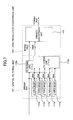
- Fig.6 is a block diagram showing an example of the construction of the spatial filtering unit 102 and the high-resolution conversion unit 103 shown in Fig.1.
- the spatial filtering unit 102 includes four line delays (FIFO 8k x 8) 111a through 111d corresponding to four horizontal lines, and further includes a filtering unit (7 x 5) 112 for performing 7-pixel-by-5-pixel filtering on image data.
- the high-resolution conversion unit 103 includes a line delay (FIFO 8k x 16) 121 corresponding to one horizontal line, and further includes a density conversion unit 122.
- the filtering unit 112 carries out filtering on a 5-line-by-5-line basis in the sub-scan direction.
- the line delays (FIFO 8k x 8) 111a through 111c that are equal in amount to four lines become necessary.
- the density conversion unit 122 converts 600-dpi image data into 1200-dpi image data as described in connection with Figs.3A through 3C, which requires the line delay (FIFO 8k x 16) 121 that is equal in amount to one line.
- Fig.7 is a block diagram showing another example of the construction of the spatial filtering unit 102 and the high-resolution conversion unit 103 shown in Fig.1.
- the spatial filtering unit 102 includes five line delays (FIFO 8k x 8) 111a through 111e and two filtering units (7 x 5) 112a and 112b for performing 7-pixel-by-5-pixel filtering on image data.
- the high-resolution conversion unit 103 includes the density conversion unit 122 that converts image data into high-resolution image data when the image data is supplied from the filtering units 112a and 112b.
- image data having been subjected filtering with a broader dynamic range is converted into high-resolution image data not by use of a line delay, but by use of a plurality of filtering operations that are performed concurrently on the 8-bit image data, part of which is delayed by a line delay before the filtering operation.
- the five line delays (FIFO 8k x 8) 111a through 111e delay the 8-bit data prior to the filter operation.
- the filtering units 112a and 112b then perform filtering operations concurrently, and supply the respective image data to the density conversion unit 122 of the high-resolution conversion unit 103.
- the filtering unit 112b supplies filtered image data that is delayed relative to the image data of the filtering unit 112a in the sub-scan direction by such a line delay as necessary for the density conversion.
- the density conversion unit 122 processes the 16-bit filtered data as described in connection with Fig.2.
- the 1200-dpi generated data is the same as the data generated by the construction shown in Fig.6.
- the construction of Fig.7 has four FIFO memories (8k x k) that are one-memory fewer.
- the line delay (FIFO 8k x 16) 121 is worth two FIFO memories having 8k-x-8 construction, resulting in the total of 6 line delays if the line delays (FIFO 8k x 8) 111a through 111d are included.
- only 5 FIFO (8k x 8) memories are used, which is one-memory fewer than the number of FIFO (8k x 8) memories used in the construction of Fig.6.
- Fig.7 needs twice as much hardware for filtering (i.e., filtering unit) as needed for the construction of Fig.6.
- the size of the filtering unit is significantly smaller than the size of a FIFO memory, so that the construction of Fig.7 can maintain the same performance as that of Fig.6 while reducing the amount of hardware in its entirety.
- Fig.7 provides a plurality of filter circuits, which concurrently generate respective'image data that are spaced apart in the sub-scan direction by such a number of lines as necessary for the conversion of image resolution. This reduces the size of FIFO memories that is necessary for the conversion of image resolution.
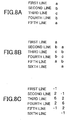
- Fig.7 can reduce the memory size compared with the construction of Fig.6, but suffers a drawback in that the amount of computation increases. If the filtering computation is performed by hardware, no problem arises since the size of filter circuits are significantly smaller than the size of FIFO memories. If the filtering computation is carried out by a CPU or the like, however, an increase in the computation load will present a problem. In the construction of Fig.7, therefore, the filter coefficients of the filtering units 112a and 112b may be defined as follows in order to reduce the amount of computation. In the following, for the sake of simplicity of explanation, a description will be given only with regard to filter coefficients of the filter in the sub-scan direction. Figs.8A through 8D are illustrative drawings for explaining an example of the filter coefficients used in the filtering units 112a and 112b.
- filter coefficients are selected in such a manner that a result of multiplication by a given coefficient will be obtained from a result of multiplication by another coefficient.
- the filter coefficients a, b, and c are -1, 2, and 6, respectively, for example.
- the following multiplication is to be further made with respect to each line: second line: -1; third line: 2; forth line: 6; fifth line: 2; and sixth line -1.
- Use of such filter coefficients makes it possible to perform the following operation.
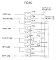
- Fig.8D is an illustrative drawing showing a construction that performs the filtering operation as described above.
- the construction shown in Fig.8D includes inverting units 151a through 151d, multiplication-by-two operation unit 152a through 152d, multiplication-by-four operation units 153a through 153b, and adders 154a and 154b.
- the multiplication-by-two operation unit 152b multiplies the data of the third line by 2, the result of which is output from the filtering unit 112a.
- the multiplication-by-four operation unit 153 multiplies the data of the third line by 4.
- the result of multiplication by 2 and the result of multiplication by 4 are added together by the adder 154a, thereby generating an output of the filtering unit 112b.
- the filter coefficients are selected such that a result of calculation based on a given filter coefficient can be obtained from a result of calculation based on another filter coefficient.
- This allows a plurality of filtering units to operate concurrently without having a proportionate increase in the amount of processing in commensurate with the number of filtering units. Accordingly, it is possible to achieve high speed processing by efficient computation when a CPU or the like performs filtering. Even when filtering is performed by dedicated hardware, an advantageous effect is obtained in that the size of circuitry is reduced. Especially, if provision is made to use only multiplication by 2 n (n: integer) for filtering operation, shift operations are all that is necessary. This achieves efficient processing.
- the input unit 101 scans image data
- the spatial filtering unit 102 performs spatial filtering on the image data supplied form the input unit 101 such as to provide a broader dynamic range.
- the high-resolution conversion unit 103 interpolates the image data processed by the spatial filtering unit 102 to convert the image data into high-resolution image data, followed by limiting the dynamic range.
- moiré is suppressed even when the moiré is generated by interference between the intervals of screen dots of the original document and the sampling interval used for obtaining pixel values at the time of image scans, or even when the moiré is generated by non-linear processing such as data saturation during spatial filtering or strong gamma processing.
- the image data is interpolated to generate high-resolution image data
- two pixels adjacent in the main scan direction are averaged for use in interpolation regarding the main scan direction
- two pixels adjacent in the sub-scan direction are averaged for use in interpolation regarding the sub-scan direction.
- four pixels surrounding a pixel of interest are averaged for use in interpolation regarding a diagonal direction.
- Fig.9 is a block diagram showing a schematic construction of the image processing apparatus according to a second embodiment of the present invention.
- the image processing apparatus of Fig.9 includes an input unit 201, a high-resolution conversion unit 202, a spatial filtering unit 203, a gamma correction unit 204, a halftone processing unit 205, and an output unit 206.
- the input unit 201 may be a scanner or the like, and obtains image data by scanning a document.
- the high-resolution conversion unit 202 changes image resolution to higher image resolution by interpolating the image data obtained by the input unit 201.
- the spatial filtering unit 203 applies spatial filtering to the image data supplied from the high-resolution conversion unit 202.
- the gamma correction unit 204 applies gamma correction to the image data supplied from the spatial filtering unit 203.
- the input unit 201 includes a 600-dpi/8-bit scanner.
- the input unit 201 scans the image data of a document, and supplies 600-dpi/8-bit image data to the high-resolution conversion unit 202.
- the high-resolution conversion unit 202 converts image resolution into higher image resolution with respect to the 600-dpi/8-bit image data supplied from the input unit 201, followed by supplying 1200-dpi/8-bit image data to the spatial filtering unit 203.
- the high-resolution conversion unit 202 performs the same interpolation as that performed by the high-resolution conversion unit 103 of the first embodiment.
- the spatial filtering unit 203 applies spatial filtering to the 1200-dpi/8-bit image data supplied from the high-resolution conversion unit 202.
- the spatial filtering unit 203 then supplies 1200-dpi/8-bit image data to the gamma correction unit 204,
- the gamma correction unit 204 applies gamma conversion to the 1200-dpi/8-bit image data supplied from the spatial filtering unit 203, and supplies the 1200-dpi/8-bit image data to the halftone processing unit 205.
- the halftone processing unit 205 performs halftone processing on the 1200-dpi/8-bit image data transferred from the gamma correction unit 204 so as to binarize the image data, thereby providing 1200-dpi/1-bit image data to the output unit 206.
- binarization is employed in this example, conversion into multi-value data may alternatively be performed.
- the output unit 206 includes a printer unit, and prints the 1200-dpi/1-bit image data on a paper sheet when the image data is supplied from the halftone processing unit 205.
- the input unit 201 scans image data, and the high-resolution conversion unit 202 interpolates the image data supplied form the input unit 201 to convert image resolution to higher image resolution.
- the spatial filtering unit 203 applies spatial filtering to the image data that has undergone image-resolution conversion by the high-resolution conversion unit 202.
- moiré is suppressed even when the moiré is generated by interference between the intervals of screen dots of the original document and the sampling interval used for obtaining pixel values at the time of image scans, or even when the moiré is generated by non-linear processing such as data saturation during spatial filtering or strong gamma processing.
- the image data is interpolated to generate high-resolution image data
- two pixels adjacent in the main scan direction are averaged for use in interpolation regarding the main scan direction
- two pixels adjacent in the sub-scan direction are averaged for use in interpolation regarding the sub-scan direction.
- four pixels surrounding a pixel of interest are averaged for use in interpolation regarding a diagonal direction.
- Fig.10 is a block diagram showing a schematic construction of the image processing apparatus according to a third embodiment of the present invention.
- the image processing apparatus of Fig.1 includes an input unit 301, a spatial filtering unit 302, a high-resolution conversion unit 303, a gamma correction unit 304, a low-resolution conversion unit 305, a halftone processing unit 306, and an output unit 307.
- the input unit 301 may be a scanner, and obtains image data by scanning a document.
- the spatial filtering unit 302 applies spatial filtering to the image data such that the spatial filtering provides a broader dynamic range.
- the high-resolution conversion unit 303 changes image resolution to higher image resolution by interpolating the image data processed by the spatial filtering unit 302.
- the gamma correction unit 304 applies gamma correction to the image data that is given higher resolution by the high-resolution conversion unit 303.
- the low-resolution conversion unit 305 converts high image resolution into low image resolution with respect to the image data that has undergone gamma correction by the gamma correction unit 304.
- the input unit 301 includes a 600-dpi/8-bit scanner.
- the input unit 301 scans the image data of a document, and supplies 600-dpi/8-bit image data to the spatial filtering unit 302.
- the spatial filtering unit 302 applies spatial filtering to the 600-dpi/8-bit image data supplied from the input unit 301 such that the spatial filtering provides a broader dynamic range for output values (16 bits) than for input values (8 bits).
- the spatial filtering unit 302 thus supplies 600-dpi/16-bit image data to the high-resolution conversion unit 303.
- the high-resolution conversion unit 303 changes image resolution and restricts the dynamic range with respect to the 600-dpi/16-bit image data supplied from the spatial filtering unit 302. As a result, the high-resolution conversion unit 303 supplies 1200-dpi/8-bit image data to the gamma correction unit 304.
- the spatial filtering unit 302 and the high-resolution conversion unit 303 may have the same constructions as the spatial filtering unit 102 and the high-resolution conversion unit 103, respectively, of the first embodiment.
- the gamma correction unit 304 applies gamma conversion to the 1200-dpi/8-bit image data supplied from the high-resolution conversion unit 303, and supplies the 1200-dpi/8-bit image data to the low-resolution conversion unit 305.
- the low-resolution conversion unit 305 converts image resolution into lower image resolution with respect to the 1200-dpi/8-bit image data supplied from the gamma correction unit 304, thereby supplying 600-dpi/8-bit image data to the halftone processing unit 306. Since high frequency components are unnecessary and undesirably cause moiré, it is preferable to apply a smoothing filter that cuts off high frequency components prior to the conversion of image resolution into lower image resolution.
- the filter (4) shown in Fig.5 would be best suited for this purpose. In practice, however, the filter (5) produces almost the same image quality in output images.
- the filter (5) i.e., the filters shown in Figs.3A through 3C
- the halftone processing unit 306 performs halftone processing on the 600-dpi/8-bit image data transferred from the low-resolution conversion unit 305 so as to binarize the image data, thereby providing 600-dpi/1-bit image data to the output unit 307.
- binarization is employed in this example, conversion into multi-value data may alternatively be performed.
- the output unit 307 includes a printer unit, and prints the 600-dpi/1-bit image data on a paper sheet when the image data is supplied from the halftone processing unit 306.
- the input unit 301 scans image data
- the spatial filtering unit 302 performs spatial filtering on the image data supplied from the input unit 301 such as to provide a broader dynamic range.
- the high-resolution conversion unit 303 interpolates the image data processed by the spatial filtering unit 302 to convert the image data into high-resolution image data, followed by limiting the dynamic range.
- the low-resolution conversion unit 305 converts the high-resolution image data into low-resolution image data.
- moiré is suppressed even when the moiré is generated by interference between the intervals of screen dots of the original document and the sampling interval used for obtaining pixel values at the time of image scans, or even when the moiré is generated by non-linear processing such as data saturation during spatial filtering or strong gamma processing.
- image data is interpolated to generate high-resolution image data, or when filtering is applied prior to the conversion of image resolution into lower image resolution, two pixels adjacent in the main scan direction are averaged for use in interpolation regarding the main scan direction, and two pixels adjacent in the sub-scan direction are averaged for use in interpolation regarding the sub-scan direction.
Landscapes
- Engineering & Computer Science (AREA)
- Physics & Mathematics (AREA)
- General Physics & Mathematics (AREA)
- Theoretical Computer Science (AREA)
- Multimedia (AREA)
- Signal Processing (AREA)
- Image Processing (AREA)
- Facsimile Image Signal Circuits (AREA)
- Editing Of Facsimile Originals (AREA)
Abstract
Description
Claims (11)
- An image processing apparatus, comprisinga spatial filtering unit which applies spatial filtering to input image data to generate filtered image data such that said spatial filtering provides a broader dynamic range for outputs than for inputs; anda high-resolution conversion unit which interpolates the filtered image data in a first direction by an average of values of two pixels adjacent in the first direction, in a second direction perpendicular to the first direction by an average of values of two pixels adjacent in the second direction, and in a direction diagonal to the first and second directions by an average of four pixels surrounding a pixel of interest, thereby converting the filtered image data into high-resolution image data.
- The image processing apparatus as claimed in claim 1, further comprising:a unit which limits the dynamic range of the high-resolution image data; anda low-resolution conversion unit which converts the high-resolution image data having the limited dynamic range into low-resolution image data.
- The image processing apparatus as claimed. in claim 2, wherein said low-resolution conversion unit filters the high-resolution image data having the limited dynamic range in the first direction by an average of values of two pixels adjacent in the first direction, in the second direction by an average of values of two pixels adjacent in the second direction, and in the diagonal direction by an average of four pixels surrounding a pixel of interest, thereby cutting off high-frequency components of the high-resolution image data having the limited dynamic range prior to the conversion of the high-resolution image data having the limited dynamic range into the low-resolution image data.
- The image processing apparatus as claimed in claim 1, 2 or 3, wherein said spatial filtering unit includes a plurality of filter circuits, said plurality of filter circuits applying spatial filtering concurrently to a plurality of lines of the input image data, so as to generate a plurality of the filtered image data concurrently that are spaced apart in the second direction by a predetermined number of lines, said plurality of the filtered image data being supplied to the high-resolution conversion unit.
- The image processing apparatus as claimed in claim 4, wherein a first filter circuit of said plurality of filter circuits multiplies a line of the input image data by a first filter coefficient, and a second filter circuit of said plurality of filter circuits multiplies the line of the input image data by a second filter coefficient by utilizing a result of the multiplication by said first filter circuit.
- The information processing apparatus as claimed in claim 1, 2, 3, 4 or 5 implemented as a board having a semiconductor integrated circuit mounted thereon, said semiconductor integrated circuit implementing said spatial filtering unit and said high-resolution conversion unit.
- An information processing apparatus, comprisingan input unit which optically scans a document to generate input image data;a spatial filtering unit which applies spatial filtering to the input image data to generate filtered image data such that said spatial filtering provides a broader dynamic range for outputs than for inputs;a high-resolution conversion unit which interpolates the filtered image data in a first direction by an average of values of two pixels adjacent in the first direction, in a second direction perpendicular to the first direction by an average of values of two pixels adjacent in the second direction, and in a direction diagonal to the first and second directions by an average of four pixels surrounding a pixel of interest, thereby converting the filtered image data into high-resolution image data, followed by limiting the dynamic range of the high-resolution image data; andan output unit which prints, on a paper sheet, image data that has undergone predetermined processing after being output from said high-resolution conversion unit.
- An image processing apparatus, comprising:a high-resolution conversion unit which interpolates input image data in a first direction by an average of values of two pixels adjacent in the first direction, in a second direction perpendicular to the first direction by an average of values of two pixels adjacent in the second direction, and in a direction diagonal to the first and second directions by an average of four pixels surrounding a pixel of interest, thereby converting the input image data into high-resolution image data; anda spatial filtering unit which applies spatial filtering to the high-resolution image data.
- A method of processing an image, comprising the steps of:applying spatial filtering to input image data to generate filtered image data such that said spatial filtering provides a broader dynamic range for outputs than for inputs; andinterpolating the filtered image data in a first direction by an average of values of two pixels adjacent in the first direction, in a second direction perpendicular to the first direction by an average of values of two pixels adjacent in the second direction, and in a direction diagonal to the first and second directions by an average of four pixels surrounding a pixel of interest, thereby converting the filtered image data into high-resolution image data.
- The method as claimed in claim 9, further comprising the steps of:limiting the dynamic range of the high-resolution image data; andconverting the high-resolution image data having the limited dynamic range into low-resolution image data.
- The method as claimed in claim 10, wherein said step of converting the high-resolution image data having the limited dynamic range into low-resolution image data includes filtering the high-resolution image data having the limited dynamic range in the first direction by an average of values of two pixels adjacent in the first direction, in the second direction by an average of values of two pixels adjacent in the second direction, and in the diagonal direction by an average of four pixels surrounding a pixel of interest, thereby cutting off high-frequency components of the high-resolution image data having the limited dynamic range prior to the conversion of the high-resolution image data having the limited dynamic range into the low-resolution image data.
Applications Claiming Priority (4)
| Application Number | Priority Date | Filing Date | Title |
|---|---|---|---|
| JP2001367702 | 2001-11-30 | ||
| JP2001367702 | 2001-11-30 | ||
| JP2002342093 | 2002-11-26 | ||
| JP2002342093A JP2003230010A (en) | 2001-11-30 | 2002-11-26 | Image processing apparatus and image processing method |
Publications (3)
| Publication Number | Publication Date |
|---|---|
| EP1317134A2 true EP1317134A2 (en) | 2003-06-04 |
| EP1317134A3 EP1317134A3 (en) | 2005-03-09 |
| EP1317134B1 EP1317134B1 (en) | 2009-07-01 |
Family
ID=26624819
Family Applications (1)
| Application Number | Title | Priority Date | Filing Date |
|---|---|---|---|
| EP02258144A Expired - Lifetime EP1317134B1 (en) | 2001-11-30 | 2002-11-27 | Image processing apparatus and method that avoids generation of moiré |
Country Status (4)
| Country | Link |
|---|---|
| US (1) | US7206002B2 (en) |
| EP (1) | EP1317134B1 (en) |
| JP (1) | JP2003230010A (en) |
| DE (1) | DE60232772D1 (en) |
Cited By (1)
| Publication number | Priority date | Publication date | Assignee | Title |
|---|---|---|---|---|
| CN101001387B (en) * | 2006-01-11 | 2010-05-12 | 华晶科技股份有限公司 | Method for judging minimum direction of image local information change by utilizing majority decision |
Families Citing this family (56)
| Publication number | Priority date | Publication date | Assignee | Title |
|---|---|---|---|---|
| US7064740B2 (en) | 2001-11-09 | 2006-06-20 | Sharp Laboratories Of America, Inc. | Backlit display with improved dynamic range |
| JP2004336453A (en) * | 2003-05-08 | 2004-11-25 | Ricoh Co Ltd | Copying machine, image processing system, program and storage medium |
| JP2004336487A (en) * | 2003-05-08 | 2004-11-25 | Ricoh Co Ltd | Facsimile apparatus, program and storage medium |
| JP2004341760A (en) * | 2003-05-15 | 2004-12-02 | Ricoh Co Ltd | Image forming apparatus, program, and storage medium |
| US8471852B1 (en) | 2003-05-30 | 2013-06-25 | Nvidia Corporation | Method and system for tessellation of subdivision surfaces |
| US7623105B2 (en) | 2003-11-21 | 2009-11-24 | Sharp Laboratories Of America, Inc. | Liquid crystal display with adaptive color |
| US7532192B2 (en) | 2004-05-04 | 2009-05-12 | Sharp Laboratories Of America, Inc. | Liquid crystal display with filtered black point |
| US7777714B2 (en) | 2004-05-04 | 2010-08-17 | Sharp Laboratories Of America, Inc. | Liquid crystal display with adaptive width |
| US8395577B2 (en) | 2004-05-04 | 2013-03-12 | Sharp Laboratories Of America, Inc. | Liquid crystal display with illumination control |
| US7612757B2 (en) | 2004-05-04 | 2009-11-03 | Sharp Laboratories Of America, Inc. | Liquid crystal display with modulated black point |
| US7505018B2 (en) | 2004-05-04 | 2009-03-17 | Sharp Laboratories Of America, Inc. | Liquid crystal display with reduced black level insertion |
| US7602369B2 (en) | 2004-05-04 | 2009-10-13 | Sharp Laboratories Of America, Inc. | Liquid crystal display with colored backlight |
| US7872631B2 (en) | 2004-05-04 | 2011-01-18 | Sharp Laboratories Of America, Inc. | Liquid crystal display with temporal black point |
| US7023451B2 (en) | 2004-06-14 | 2006-04-04 | Sharp Laboratories Of America, Inc. | System for reducing crosstalk |
| CN1728761A (en) * | 2004-06-16 | 2006-02-01 | 株式会社理光 | Image processing device, image processing method, and image processing program |
| US7556836B2 (en) | 2004-09-03 | 2009-07-07 | Solae, Llc | High protein snack product |
| US7898519B2 (en) | 2005-02-17 | 2011-03-01 | Sharp Laboratories Of America, Inc. | Method for overdriving a backlit display |
| US8050511B2 (en) | 2004-11-16 | 2011-11-01 | Sharp Laboratories Of America, Inc. | High dynamic range images from low dynamic range images |
| US8050512B2 (en) | 2004-11-16 | 2011-11-01 | Sharp Laboratories Of America, Inc. | High dynamic range images from low dynamic range images |
| US7525528B2 (en) | 2004-11-16 | 2009-04-28 | Sharp Laboratories Of America, Inc. | Technique that preserves specular highlights |
| US8571346B2 (en) * | 2005-10-26 | 2013-10-29 | Nvidia Corporation | Methods and devices for defective pixel detection |
| US7750956B2 (en) * | 2005-11-09 | 2010-07-06 | Nvidia Corporation | Using a graphics processing unit to correct video and audio data |
| US8588542B1 (en) * | 2005-12-13 | 2013-11-19 | Nvidia Corporation | Configurable and compact pixel processing apparatus |
| US9143657B2 (en) | 2006-01-24 | 2015-09-22 | Sharp Laboratories Of America, Inc. | Color enhancement technique using skin color detection |
| US8737832B1 (en) | 2006-02-10 | 2014-05-27 | Nvidia Corporation | Flicker band automated detection system and method |
| JP4232113B2 (en) * | 2006-02-17 | 2009-03-04 | ソニー株式会社 | Data processing apparatus, data processing method, and program |
| US8594441B1 (en) | 2006-09-12 | 2013-11-26 | Nvidia Corporation | Compressing image-based data using luminance |
| US8049685B2 (en) * | 2006-11-09 | 2011-11-01 | Global Oled Technology Llc | Passive matrix thin-film electro-luminescent display |
| US8941580B2 (en) | 2006-11-30 | 2015-01-27 | Sharp Laboratories Of America, Inc. | Liquid crystal display with area adaptive backlight |
| US8553758B2 (en) * | 2007-03-02 | 2013-10-08 | Sony Corporation | Motion parameter engine for true motion |
| US8723969B2 (en) * | 2007-03-20 | 2014-05-13 | Nvidia Corporation | Compensating for undesirable camera shakes during video capture |
| US8724895B2 (en) | 2007-07-23 | 2014-05-13 | Nvidia Corporation | Techniques for reducing color artifacts in digital images |
| US8570634B2 (en) * | 2007-10-11 | 2013-10-29 | Nvidia Corporation | Image processing of an incoming light field using a spatial light modulator |
| JP4912270B2 (en) * | 2007-10-16 | 2012-04-11 | キヤノン株式会社 | Image processing apparatus and control method thereof |
| US9177368B2 (en) * | 2007-12-17 | 2015-11-03 | Nvidia Corporation | Image distortion correction |
| US8780128B2 (en) * | 2007-12-17 | 2014-07-15 | Nvidia Corporation | Contiguously packed data |
| US8698908B2 (en) * | 2008-02-11 | 2014-04-15 | Nvidia Corporation | Efficient method for reducing noise and blur in a composite still image from a rolling shutter camera |
| US9379156B2 (en) * | 2008-04-10 | 2016-06-28 | Nvidia Corporation | Per-channel image intensity correction |
| US8363728B2 (en) * | 2008-04-18 | 2013-01-29 | Sony Corporation | Block based codec friendly edge detection and transform selection |
| US8139883B2 (en) * | 2008-07-29 | 2012-03-20 | Sony Corporation | System and method for image and video encoding artifacts reduction and quality improvement |
| US20100067818A1 (en) * | 2008-09-15 | 2010-03-18 | Sony Corporation, A Japanese Corporation | System and method for high quality image and video upscaling |
| US8373718B2 (en) | 2008-12-10 | 2013-02-12 | Nvidia Corporation | Method and system for color enhancement with color volume adjustment and variable shift along luminance axis |
| US8749662B2 (en) * | 2009-04-16 | 2014-06-10 | Nvidia Corporation | System and method for lens shading image correction |
| US9008464B2 (en) * | 2009-06-16 | 2015-04-14 | University-Industry Cooperation Group Of Kyung Hee University | Media data customization |
| US8698918B2 (en) * | 2009-10-27 | 2014-04-15 | Nvidia Corporation | Automatic white balancing for photography |
| JP5803268B2 (en) | 2010-07-23 | 2015-11-04 | 株式会社リコー | Image forming apparatus, image forming method, and program |
| JP2013024564A (en) | 2011-07-14 | 2013-02-04 | Ricoh Co Ltd | Image inspection apparatus, image inspection system and image inspection method |
| CN102523373A (en) * | 2011-12-07 | 2012-06-27 | 天津天地伟业物联网技术有限公司 | Filtering noise reduction system and filtering noise reduction method of video data |
| US9798698B2 (en) | 2012-08-13 | 2017-10-24 | Nvidia Corporation | System and method for multi-color dilu preconditioner |
| US9508318B2 (en) | 2012-09-13 | 2016-11-29 | Nvidia Corporation | Dynamic color profile management for electronic devices |
| JP6097524B2 (en) * | 2012-10-29 | 2017-03-15 | キヤノン株式会社 | Image processing method, image processing apparatus, and program |
| US9307213B2 (en) | 2012-11-05 | 2016-04-05 | Nvidia Corporation | Robust selection and weighting for gray patch automatic white balancing |
| US9418400B2 (en) | 2013-06-18 | 2016-08-16 | Nvidia Corporation | Method and system for rendering simulated depth-of-field visual effect |
| US9826208B2 (en) | 2013-06-26 | 2017-11-21 | Nvidia Corporation | Method and system for generating weights for use in white balancing an image |
| US9756222B2 (en) | 2013-06-26 | 2017-09-05 | Nvidia Corporation | Method and system for performing white balancing operations on captured images |
| JP7424076B2 (en) | 2020-01-29 | 2024-01-30 | 株式会社リコー | Image processing device, image processing system, imaging device, image processing method and program |
Family Cites Families (22)
| Publication number | Priority date | Publication date | Assignee | Title |
|---|---|---|---|---|
| US4987496A (en) * | 1989-09-18 | 1991-01-22 | Eastman Kodak Company | System for scanning halftoned images |
| US5513016A (en) * | 1990-10-19 | 1996-04-30 | Fuji Photo Film Co. | Method and apparatus for processing image signal |
| US5387983A (en) * | 1991-09-27 | 1995-02-07 | Minolta Camera Kabushiki Kaisha | Facsimile apparatus comprising converting means for converting binary image data into multi-value image data and image processing apparatus judging pseudo half-tone image |
| JPH0630263A (en) * | 1992-07-13 | 1994-02-04 | Mita Ind Co Ltd | Color image processing circuit |
| US5608824A (en) * | 1993-01-22 | 1997-03-04 | Olympus Optical Co., Ltd. | Image processing apparatus in which filters having different filtering characteristics can be switched among themselves |
| US6319682B1 (en) * | 1995-10-04 | 2001-11-20 | Cytoscan Sciences, L.L.C. | Methods and systems for assessing biological materials using optical and spectroscopic detection techniques |
| US6118547A (en) * | 1996-07-17 | 2000-09-12 | Canon Kabushiki Kaisha | Image processing method and apparatus |
| JPH11177744A (en) | 1997-12-08 | 1999-07-02 | Ricoh Co Ltd | Digital linked copy system |
| JP3733446B2 (en) | 1998-03-12 | 2006-01-11 | 株式会社リコー | Digital copier |
| JP3660182B2 (en) | 1999-12-03 | 2005-06-15 | 株式会社リコー | Image processing device |
| JP2001169068A (en) | 1999-12-14 | 2001-06-22 | Ricoh Co Ltd | IMAGE PROCESSING DEVICE, IMAGE PROCESSING METHOD, AND COMPUTER-READABLE RECORDING MEDIUM RECORDING PROGRAM FOR CAUSING COMPUTER TO EXECUTE THE METHOD |
| JP2001186332A (en) | 1999-12-27 | 2001-07-06 | Ricoh Co Ltd | IMAGE PROCESSING DEVICE, IMAGE PROCESSING METHOD, AND COMPUTER-READABLE RECORDING MEDIUM RECORDING PROGRAM FOR CAUSING COMPUTER TO EXECUTE THE METHOD |
| US7038818B2 (en) | 1999-12-27 | 2006-05-02 | Ricoh Company, Ltd | Method and apparatus for image processing method, and a computer product |
| JP3922859B2 (en) | 1999-12-28 | 2007-05-30 | 株式会社リコー | Image processing apparatus, image processing method, and computer-readable recording medium storing program for causing computer to execute the method |
| JP3732702B2 (en) | 2000-01-31 | 2006-01-11 | 株式会社リコー | Image processing device |
| JP3789711B2 (en) | 2000-01-31 | 2006-06-28 | 株式会社リコー | Image processing device |
| JP2001273267A (en) | 2000-03-27 | 2001-10-05 | Ricoh Co Ltd | SIMD type processor, parallel processing device, image processing device, copier, printer, facsimile device, scanner, parallel processing method, image processing method, and computer-readable recording medium storing a program for causing a computer to execute the method |
| JP2001320584A (en) | 2000-05-08 | 2001-11-16 | Ricoh Co Ltd | Image processing apparatus and image forming apparatus |
| JP4148655B2 (en) | 2000-09-01 | 2008-09-10 | 株式会社リコー | Image reading apparatus, image forming apparatus, and white reference data creation method |
| JP3907155B2 (en) | 2000-09-04 | 2007-04-18 | 株式会社リコー | Image data correction apparatus, image reading apparatus, and image forming apparatus |
| JP4086520B2 (en) | 2001-03-19 | 2008-05-14 | 株式会社リコー | Multi-valued image encoding and decoding method and apparatus |
| JP4129812B2 (en) | 2001-05-24 | 2008-08-06 | 株式会社リコー | Image processing method, apparatus, and image forming apparatus |
-
2002
- 2002-11-26 JP JP2002342093A patent/JP2003230010A/en active Pending
- 2002-11-27 DE DE60232772T patent/DE60232772D1/en not_active Expired - Lifetime
- 2002-11-27 US US10/305,102 patent/US7206002B2/en not_active Expired - Fee Related
- 2002-11-27 EP EP02258144A patent/EP1317134B1/en not_active Expired - Lifetime
Cited By (1)
| Publication number | Priority date | Publication date | Assignee | Title |
|---|---|---|---|---|
| CN101001387B (en) * | 2006-01-11 | 2010-05-12 | 华晶科技股份有限公司 | Method for judging minimum direction of image local information change by utilizing majority decision |
Also Published As
| Publication number | Publication date |
|---|---|
| JP2003230010A (en) | 2003-08-15 |
| EP1317134B1 (en) | 2009-07-01 |
| US20030122825A1 (en) | 2003-07-03 |
| US7206002B2 (en) | 2007-04-17 |
| DE60232772D1 (en) | 2009-08-13 |
| EP1317134A3 (en) | 2005-03-09 |
Similar Documents
| Publication | Publication Date | Title |
|---|---|---|
| EP1317134B1 (en) | Image processing apparatus and method that avoids generation of moiré | |
| CA2132248C (en) | Apparatus and method for arbitrary binary resolution conversion | |
| US6101285A (en) | Filter for producing continuous tone images from halftone digital images data | |
| US6839152B2 (en) | Adaptive filtering method and apparatus for descreening scanned halftoned image representations | |
| US5513016A (en) | Method and apparatus for processing image signal | |
| US9215345B2 (en) | Method and system for inverse halftoning utilizing inverse projection of predicted errors | |
| US20090097776A1 (en) | Image processing apparatus and control method therefor | |
| JP3912633B2 (en) | Image processing method and apparatus | |
| CN1717919A (en) | Image processing apparatus | |
| JP3176195B2 (en) | Image processing device | |
| US20080266580A1 (en) | Scaling methods for binary image data | |
| EP0817466A2 (en) | Edge enhanced error diffusion | |
| EP2111032B1 (en) | Image processing apparatus and method thereof | |
| JP4610517B2 (en) | Method and system for extending binary image data to contone image data | |
| US5701363A (en) | Binary to multi-value conversion apparatus for improved image reduction and enlargement | |
| JP2010278933A (en) | Image processing apparatus, image forming apparatus, image processing method, program, and recording medium | |
| US7106478B2 (en) | Image processing device and method for controlling the same | |
| US6285803B1 (en) | Method and apparatus for resolution enhancement by synthesis of scan signals | |
| JP3631609B2 (en) | Image processing apparatus and image processing method | |
| JP2746772B2 (en) | Image signal processing method and apparatus | |
| JP3784537B2 (en) | Image processing device | |
| US8331732B2 (en) | Binary reduction with structure preservation and density control | |
| JP3729612B2 (en) | Image processing apparatus and image processing method | |
| JPH1141602A (en) | Image processing device | |
| JPH11252368A (en) | Image processing device |
Legal Events
| Date | Code | Title | Description |
|---|---|---|---|
| PUAI | Public reference made under article 153(3) epc to a published international application that has entered the european phase |
Free format text: ORIGINAL CODE: 0009012 |
|
| 17P | Request for examination filed |
Effective date: 20021127 |
|
| AK | Designated contracting states |
Designated state(s): AT BE BG CH CY CZ DE DK EE ES FI FR GB GR IE IT LI LU MC NL PT SE SK TR |
|
| AX | Request for extension of the european patent |
Extension state: AL LT LV MK RO SI |
|
| PUAL | Search report despatched |
Free format text: ORIGINAL CODE: 0009013 |
|
| AK | Designated contracting states |
Kind code of ref document: A3 Designated state(s): AT BE BG CH CY CZ DE DK EE ES FI FR GB GR IE IT LI LU MC NL PT SE SK TR |
|
| AX | Request for extension of the european patent |
Extension state: AL LT LV MK RO SI |
|
| AKX | Designation fees paid |
Designated state(s): DE FR GB |
|
| 17Q | First examination report despatched |
Effective date: 20051012 |
|
| GRAP | Despatch of communication of intention to grant a patent |
Free format text: ORIGINAL CODE: EPIDOSNIGR1 |
|
| GRAS | Grant fee paid |
Free format text: ORIGINAL CODE: EPIDOSNIGR3 |
|
| GRAA | (expected) grant |
Free format text: ORIGINAL CODE: 0009210 |
|
| AK | Designated contracting states |
Kind code of ref document: B1 Designated state(s): DE FR GB |
|
| REG | Reference to a national code |
Ref country code: GB Ref legal event code: FG4D |
|
| REF | Corresponds to: |
Ref document number: 60232772 Country of ref document: DE Date of ref document: 20090813 Kind code of ref document: P |
|
| PLBE | No opposition filed within time limit |
Free format text: ORIGINAL CODE: 0009261 |
|
| STAA | Information on the status of an ep patent application or granted ep patent |
Free format text: STATUS: NO OPPOSITION FILED WITHIN TIME LIMIT |
|
| 26N | No opposition filed |
Effective date: 20100406 |
|
| REG | Reference to a national code |
Ref country code: FR Ref legal event code: PLFP Year of fee payment: 14 |
|
| REG | Reference to a national code |
Ref country code: FR Ref legal event code: PLFP Year of fee payment: 15 |
|
| PGFP | Annual fee paid to national office [announced via postgrant information from national office to epo] |
Ref country code: FR Payment date: 20161118 Year of fee payment: 15 Ref country code: GB Payment date: 20161122 Year of fee payment: 15 |
|
| PGFP | Annual fee paid to national office [announced via postgrant information from national office to epo] |
Ref country code: DE Payment date: 20171121 Year of fee payment: 16 |
|
| GBPC | Gb: european patent ceased through non-payment of renewal fee |
Effective date: 20171127 |
|
| REG | Reference to a national code |
Ref country code: FR Ref legal event code: ST Effective date: 20180731 |
|
| PG25 | Lapsed in a contracting state [announced via postgrant information from national office to epo] |
Ref country code: FR Free format text: LAPSE BECAUSE OF NON-PAYMENT OF DUE FEES Effective date: 20171130 |
|
| PG25 | Lapsed in a contracting state [announced via postgrant information from national office to epo] |
Ref country code: GB Free format text: LAPSE BECAUSE OF NON-PAYMENT OF DUE FEES Effective date: 20171127 |
|
| REG | Reference to a national code |
Ref country code: DE Ref legal event code: R119 Ref document number: 60232772 Country of ref document: DE |
|
| PG25 | Lapsed in a contracting state [announced via postgrant information from national office to epo] |
Ref country code: DE Free format text: LAPSE BECAUSE OF NON-PAYMENT OF DUE FEES Effective date: 20190601 |