EP1317058A2 - Excitation controller for synchronous machine - Google Patents
Excitation controller for synchronous machine Download PDFInfo
- Publication number
- EP1317058A2 EP1317058A2 EP02010228A EP02010228A EP1317058A2 EP 1317058 A2 EP1317058 A2 EP 1317058A2 EP 02010228 A EP02010228 A EP 02010228A EP 02010228 A EP02010228 A EP 02010228A EP 1317058 A2 EP1317058 A2 EP 1317058A2
- Authority
- EP
- European Patent Office
- Prior art keywords
- voltage
- hsvc
- synchronous machine
- module type
- value
- Prior art date
- Legal status (The legal status is an assumption and is not a legal conclusion. Google has not performed a legal analysis and makes no representation as to the accuracy of the status listed.)
- Granted
Links
Images



Classifications
-
- H—ELECTRICITY
- H02—GENERATION; CONVERSION OR DISTRIBUTION OF ELECTRIC POWER
- H02P—CONTROL OR REGULATION OF ELECTRIC MOTORS, ELECTRIC GENERATORS OR DYNAMO-ELECTRIC CONVERTERS; CONTROLLING TRANSFORMERS, REACTORS OR CHOKE COILS
- H02P9/00—Arrangements for controlling electric generators for the purpose of obtaining a desired output
- H02P9/14—Arrangements for controlling electric generators for the purpose of obtaining a desired output by variation of field
- H02P9/26—Arrangements for controlling electric generators for the purpose of obtaining a desired output by variation of field using discharge tubes or semiconductor devices
- H02P9/30—Arrangements for controlling electric generators for the purpose of obtaining a desired output by variation of field using discharge tubes or semiconductor devices using semiconductor devices
- H02P9/305—Arrangements for controlling electric generators for the purpose of obtaining a desired output by variation of field using discharge tubes or semiconductor devices using semiconductor devices controlling voltage
Definitions
- the present invention relates in general to an excitation controller for a synchronous machine. More particularly, the invention relates to an excitation controller for a synchronous machine which contributes to the enhancement of stabilizing a voltage in an electric power system.
- a conventional excitation controller for a synchronous machine described in United States Patent No. US 6,265,852 B1 for example has a high side voltage control (hereinafter, referred to as "HSVC” for short, when applicable) function of controlling a high side voltage of a main transformer in such a way that it becomes equal to a control reference value.
- This HSVC function is a function which is added to an automatic voltage regulator (hereinafter, referred to as "AVR" for short, when applicable) in the form of a software.
- the present invention has been made in order to solve the above-mentioned problem associated with the prior art, and it is therefore an object of the present invention to obtain an excitation controller for a synchronous machine in which the HSVC function can be obtained without exchanging an existing AVR.
- An excitation controller for a synchronous machine includes: a voltage detector for detecting an output terminal voltage of the synchronous machine connected to a transmission system through a transformer; a current detector for detecting a current outputted by the synchronous machine; a module type HSVC (High Side Voltage Control) apparatus for operating arithmetically a reactive power on the basis of output signals from the voltage detector and the current detector, operating arithmetically a reactive current value from the generator terminal voltage and the reactive power, operating arithmetically a high side voltage value from the reactive current value thus arithmetically operated and a reactance of the transformer and outputting a correction signal based on a deviation between the high side voltage value thus arithmetically operated and a voltage setting value; an automatic voltage regulator, having a voltage setter, for outputting a command which is obtained by adding the correction signal to a voltage setting value provided by the voltage setter; and an exciter for carrying out field control of said synchronous machine on the basis of the command issued from the automatic voltage regulator
- the module type HSVC apparatus includes an HMI (Human Machine Interface) for carrying out setting of a reference voltage, and setting and display of control logic.
- HMI Human Machine Interface
- the module type HSVC apparatus includes a connection unit having a communication function for connecting the HMI to a network.
- the module type HSVC apparatus has an input unit for inputting therethrough a voltage setting value from the automatic voltage regulator and outputs a correction signal based on a deviation between the inputted voltage setting value and the arithmetically operated high side voltage value.
- the synchronous machines are connected in parallel with one another to the transmission system through the transformer, the voltage detector, the current detector, the module type HSVC apparatus, the automatic voltage regulator, and the exciter are provided for each of the synchronous machines, and each of the module type HSVC apparatuses carries out control for suppressing a cross current on the basis of an input of a reactive power from the other module type HSVC apparatus.
- the module type HSVC apparatus includes an analog output unit for outputting therethrough an arithmetic operation result.
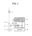
- Fig. 1 is a block diagram showing a configuration of an overall excitation controller for a synchronous machine according to Embodiment 1 of the present invention.
- the excitation controller for a synchronous machine shown in Fig. 1 is additionally provided with an excitation controller 4 which is employed in order to add an HSVC function (hereinafter, referred to as "module type HSVC apparatus" for short, when applicable) in addition to the configuration including a potential transformer (hereinafter, referred to as "PT" for short, when applicable) 2 for detecting an output voltage of a synchronous machine 1, a current transformer (hereinafter, referred to as "CT” for short, when applicable) 3 for detecting an output current of the synchronous machine 1, an existing AVR 5 for adjusting an voltage of a generator on the basis of outputs of the PT 2 and the CT 3, and an exciter 6 for controlling a field of the synchronous machine 1 on the basis of a command issued from the AVR 5.
- a potential transformer hereinafter, referred to as "PT” for
- the module type HSVC apparatus 4 is adapted to add a correction signal, which is used to provide the HSVC function, to a voltage setting value of the existing AVR 5 to control the exciter 6, and also is adapted to carry out the control in such a way that a high side voltage of a main transformer 7 becomes equal to a reference voltage setting value.
- the module type HSVC apparatus 4 arithmetically operates a terminal output, an effective power and a reactive power of a generator on the basis of the outputs from the PT 2 and the CT 3, arithmetically operates a reactive current value, which the synchronous machine 1 outputs, from the terminal voltage and the reactive power of the generator, arithmetically operates a high side voltage value from the reactive current value thus arithmetically operated and a reactance of the main transformer 7, and then outputs a correction signal in correspondence to a deviation between the high side voltage thus arithmetically operated and a reference voltage setting value.
- the module type HSVC apparatus 4 in a module case, includes: a power source circuit 8 for supplying an electric power for the module type HSVC apparatus 4; an auxiliary potential transformer/current transformer (hereinafter, referred to as "auxiliary PT/CT" for short, when applicable) 9; an analog input unit 10 for a three-phase current/voltage for reading out a terminal voltage and a current of the synchronous machine 1 through the auxiliary PT/CT 9; an arithmetic operation unit 11 for operating arithmetically a correction signal which is used to realize the HSVC function and to control the overall module on the basis of an output signal from the analog input unit 10 for a three-phase current/voltage; an analog output unit 12 for outputting the correction signal, which has been arithmetically operated in the arithmetic operation unit 11, to the existing AVR 5; a digital input unit 13 for providing a digital input signal which is used to switch the state of the function of the module type HSVC apparatus 4 over to effectiveness/
- auxiliary PT/CT
- the analog input unit 10 for a three-phase current/voltage receives as its inputs detection signals from the PT 2 and the CT 3 through the auxiliary PT/CT 9 to measure a terminal current and a terminal voltage of the synchronous machine 1.
- the arithmetic operation unit 11 arithmetically operates a generator terminal voltage, an effective power and a reactive power on the basis of an output signal from the analog input unit 10 for a three-phase current/voltage, arithmetically operates a reactive current from the generator terminal voltage and the reactive power which have been arithmetically operated, and arithmetically operates a high side voltage value from those arithmetically operated values and the known reactance of the main transformer 7. Then, the arithmetic operation unit 11 outputs a correction signal, which has been obtained on the basis of a deviation between the high side voltage value thus arithmetically operated and the setting value thereof, to the AVR 5 through the analog output unit 12.
- the module type HSVC apparatus 4 realizes the HSVC function. It should be noted that the confirmation and the change of the setting value for the arithmetic operation are both carried out through the display/setting unit 14 mounted to the module, and the use and the omission of the function are both carried out through the digital input unit 13.
- Embodiment 1 it is possible to add the HSVC function to the controller without exchanging an existing AVR.
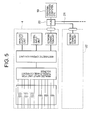
- a tool 16 such as a personal computer may also be directly connected to the arithmetic operation unit 11 in order to realize the display function and the setting function using the tool 16.
- a network connection unit 17 having a communication function to establish a connection to a network 18 may also be connected to the arithmetic operation unit 11 in order to realize the display function and the setting function of the arithmetic operation unit 11, from a distant place, by a tool 19 such as a personal computer connected to the network 18.
- this module type HSVC apparatus 4 which has been developed is mounted for each of a plurality of connected synchronous machines.
- a tool 19 such as a single personal computer may also be connected to a plurality of module type HSVC apparatuses 4, 22, etc., through a HUB 20 or the like and a network 21 in order to realize the display function and the setting function at the same time.
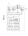
- the voltage setting value of the existing AVR 5 is inputted as the setting value from the display/setting unit 14 of the module type HSVC apparatus 4, alternatively, as shown in Fig. 6, a analog input unit 23 may also be added to read out the voltage setting value of the existing AVR in order to set automatically the voltage setting value of the existing AVR.
- Fig. 7 is a block diagram, partly in circuit diagram, showing the state in which two synchronous machines 1 and 24 are operated in parallel with each other.
- a module type HSVC apparatus 25 similarly to the synchronous machine 1, is mounted to the synchronous machine 24 as well.
- the outputs thereof become unbalanced so that a cross current is caused to flow. Therefore, the output reactive power signals of the synchronous machines 1 and 24 are outputted from the analog output units 12 to be read out by the analog input units 23, respectively, through a signal line 26 shown in Fig. 7, whereby the control of suppressing the cross current can be carried out. For this reason, the suppression of the cross current may be implemented with the configuration shown in Fig. 6.
- an output signal of the analog output unit 12 also may be outputted to a check pin (not shown) mounted to the module case to measure the internal arithmetic operation value using a measuring instrument, such as an oscilloscope.
- Embodiments 1 to 7 described above may be combined with each other to be used. Therefore, the apparatuses may be available in which the apparatuses of Embodiments 1 to 7 are simultaneously used.
- an excitation controller for a synchronous machine includes: a voltage detector for detecting an output terminal voltage of a synchronous machine connected to a transmission system through a transformer; a current detector for detecting a current outputted by the synchronous machine; a module type HSVC (High Side Voltage Control) apparatus for operating arithmetically a reactive power on the basis of output signals from the voltage detector and the current detector, operating arithmetically a reactive current value from the generator terminal voltage and the reactive power, operating arithmetically a high side voltage value from the reactive current value thus arithmetically operated and a reactance of the transformer and outputting a correction signal based on a deviation between the high side voltage value thus arithmetically operated and a voltage setting value; an automatic voltage regulator, having a voltage setter, for outputting a command which is obtained by adding the correction signal to a voltage setting value provided by the voltage setter; and an exciter for carrying out the field control of the synchronous machine on
- module type HSVC apparatus includes an HMI (Human Machine Interface) for carrying out the setting of a reference voltage, and the setting and display of control logic, it is possible to carry out readily the confirmation and change of a setting value.
- HMI Human Machine Interface
- module type HSVC apparatus includes a connection unit having a communication function for connecting the HMI to a network, it is possible to carry out readily the confirmation and change of a setting value from a distant place.
- the above-mentioned module type HSVC apparatus has an input unit for inputting therethrough a voltage setting value from the above-mentioned automatic voltage regulator and outputs a correction signal based on a deviation between the inputted voltage setting value and the arithmetically operated high side voltage value, it is possible to obtain an HSVC function without exchanging an existing AVR.
- the above-mentioned synchronous machines which are connected in parallel with one another are connected to the transmission system through a transformer, the voltage detector, the current detector, the module type HSVC apparatus, the automatic voltage regulator, and the exciter are provided for each of the synchronous machines, and each of the module type HSVC apparatuses carries out the control for suppressing a cross current on the basis of an input of a reactive power from another module type HSVC apparatus. Therefore, it is possible to carry out the control with which the synchronous machines connected to in parallel with one another cooperate.
- the above-mentioned module type HSVC apparatus includes an analog output unit for outputting therethrough the arithmetic operation result, it is possible to measure the arithmetic operation result from the outside.
Landscapes
- Engineering & Computer Science (AREA)
- Power Engineering (AREA)
- Control Of Eletrric Generators (AREA)
Abstract
Description
Claims (6)
- An excitation controller for a synchronous machine comprising:a voltage detector (2) for detecting an output terminal voltage of said synchronous machine (1) connected to a transmission system through a transformer (7);a current detector (3) for detecting a current outputted by said synchronous machine (1);a module type HSVC (High Side Voltage Control) apparatus (4) for operating arithmetically a reactive power on the basis of output signals from said voltage detector (2) and said current detector (3), operating arithmetically a reactive current value from the generator terminal voltage and the reactive power, operating arithmetically a high side voltage value from the reactive current value thus arithmetically operated and a reactance of said transformer (7) and outputting a correction signal based on a deviation between the high side voltage value thus arithmetically operated and a voltage setting value;an automatic voltage regulator (5), having a voltage setter, for outputting a command which is obtained by adding the correction signal to a voltage setting value provided by said voltage setter; andan exciter (6) for carrying out field control of said synchronous machine on the basis of the command issued from said automatic voltage regulator (5).
- An excitation controller for a synchronous machine according to claim 1, wherein said module type HSVC apparatus (4) includes an HMI (Human Machine Interface) (14) for carrying out setting of a reference voltage, and setting and display of control logic.
- An excitation controller for a synchronous machine according to claim 2, wherein said module type HSVC apparatus (4) includes a connection unit (17) having a communication function for connecting said HMI (19) to a network.
- An excitation controller for a synchronous machine according to any one of claims 1 to 3, wherein said module type HSVC apparatus (4) has an input unit (23) for inputting therethrough a voltage setting value from said automatic voltage regulator (5) and outputs a correction signal based on a deviation between the inputted voltage setting value and the arithmetically operated high side voltage value.
- An excitation controller for a synchronous machine according to any one of claims 1 to 4, wherein said synchronous machines (1, 24) are connected in parallel with one another to the transmission system through the transformer (7);
said voltage detector, said current detector, said module type HSVC apparatus (4, 25), said automatic voltage regulator, and said exciter are provided for each of said synchronous machines (1, 24); and
each of said module type HSVC apparatuses (4, 25) carries out control for suppressing a cross current on the basis of an input of a reactive power from the other module type HSVC apparatus (25, 4). - An excitation controller for a synchronous machine according to any one of claims 1 to 5, wherein said module type HSVC apparatus (4) includes an analog output unit (12) for outputting therethrough arithmetic operation result.
Applications Claiming Priority (2)
| Application Number | Priority Date | Filing Date | Title |
|---|---|---|---|
| JP2001366369 | 2001-11-30 | ||
| JP2001366369A JP2003169500A (en) | 2001-11-30 | 2001-11-30 | Excitation control device for synchronous machine |
Publications (3)
| Publication Number | Publication Date |
|---|---|
| EP1317058A2 true EP1317058A2 (en) | 2003-06-04 |
| EP1317058A3 EP1317058A3 (en) | 2005-02-02 |
| EP1317058B1 EP1317058B1 (en) | 2007-04-18 |
Family
ID=19176277
Family Applications (1)
| Application Number | Title | Priority Date | Filing Date |
|---|---|---|---|
| EP02010228A Expired - Lifetime EP1317058B1 (en) | 2001-11-30 | 2002-05-16 | Excitation controller for synchronous machine |
Country Status (5)
| Country | Link |
|---|---|
| US (1) | US6762592B2 (en) |
| EP (1) | EP1317058B1 (en) |
| JP (1) | JP2003169500A (en) |
| CN (1) | CN1266826C (en) |
| DE (1) | DE60219577T2 (en) |
Families Citing this family (20)
| Publication number | Priority date | Publication date | Assignee | Title |
|---|---|---|---|---|
| CA2379444C (en) * | 2000-06-19 | 2006-08-01 | Mitsubishi Denki Kabushiki Kaisha | Excitation control device and excitation control method |
| JP3778176B2 (en) | 2002-05-28 | 2006-05-24 | セイコーエプソン株式会社 | LIGHT EMITTING DEVICE AND ELECTRONIC DEVICE |
| US6975946B2 (en) * | 2003-06-23 | 2005-12-13 | Saudi Arabian Oil Company | Reactive power optimization with adaptive excitation control |
| US7119452B2 (en) * | 2003-09-03 | 2006-10-10 | General Electric Company | Voltage control for wind generators |
| JP4116595B2 (en) * | 2004-06-30 | 2008-07-09 | ファナック株式会社 | Motor control device |
| CN101192806B (en) * | 2006-11-23 | 2010-10-27 | 全汉企业股份有限公司 | Control method and control circuit for transformer excitation period |
| US8560201B2 (en) * | 2007-05-31 | 2013-10-15 | Caterpillar Inc. | Gen-Set control system having proactive load relief |
| WO2008147357A1 (en) * | 2007-05-31 | 2008-12-04 | Caterpillar Inc. | System and method for engine load management |
| US8058753B2 (en) * | 2008-10-31 | 2011-11-15 | General Electric Company | Wide area transmission control of windfarms |
| RU2465716C1 (en) * | 2011-07-29 | 2012-10-27 | Алексей Валериевич Бумагин | Device to control excitation of synchronous generator |
| JP5843664B2 (en) * | 2012-03-06 | 2016-01-13 | 三菱電機株式会社 | Power plant |
| US9371821B2 (en) | 2012-08-31 | 2016-06-21 | General Electric Company | Voltage control for wind turbine generators |
| US9164148B2 (en) | 2013-04-12 | 2015-10-20 | Kato Engineering Inc. | Systems and methods for detecting over/under excitation faults |
| CN104518481A (en) * | 2013-10-08 | 2015-04-15 | 山东迪生电气股份有限公司 | Method for improving overvoltage protection sensitivity of generator-transformer unit |
| CN103986383B (en) * | 2014-05-28 | 2016-06-15 | 南方电网科学研究院有限责任公司 | A reactive power-voltage comprehensive control method and its control system on the high voltage side of a power plant |
| RU2580944C1 (en) * | 2014-10-27 | 2016-04-10 | Федеральное бюджетное образовательное учреждение высшего профессионального образования "Волжская государственная академия водного транспорта" (ФБОУ ВПО ВГАВТ) | Device for correction of shape of voltage curve |
| RU2625351C1 (en) * | 2016-03-30 | 2017-07-13 | Федеральное государственное бюджетное образовательное учреждение высшего образования "Волжский государственный университет водного транспорта" (ФГБОУ ВО ВГУВТ) | Voltage compensation device |
| WO2020172578A1 (en) * | 2019-02-22 | 2020-08-27 | Basler Electric Company | Advanced cross-current compensation system and method for enhancing reactive current sharing |
| CN112072976A (en) * | 2020-07-23 | 2020-12-11 | 中国电力科学研究院有限公司 | Q-axis excitation control device of double-shaft excitation phase modulator |
| JP7341966B2 (en) * | 2020-09-16 | 2023-09-11 | 三菱重工業株式会社 | Field control device and field control method for synchronous machine |
Family Cites Families (13)
| Publication number | Priority date | Publication date | Assignee | Title |
|---|---|---|---|---|
| JPS53120117A (en) * | 1977-03-30 | 1978-10-20 | Hitachi Ltd | Excitation control system for generator |
| US4350947A (en) * | 1980-02-25 | 1982-09-21 | Fuji Electric Co. Ltd. | System for predicting desynchronization of a synchronous machine |
| US4639657A (en) * | 1984-08-30 | 1987-01-27 | Basler Electric Company | Electrical control apparatus and methods |
| JPS6216098A (en) * | 1985-07-10 | 1987-01-24 | Toshiba Corp | Controller for excitation of synchronous machine |
| US5045779A (en) * | 1986-05-06 | 1991-09-03 | General Electric Company | Method and apparatus for testing dynamoelectric machine rotors |
| US4812729A (en) * | 1986-08-19 | 1989-03-14 | Hitachi Ltd. | Protecting apparatus for secondary excitation type variable speed AC generator/motor |
| US5440222A (en) * | 1991-07-15 | 1995-08-08 | Mitsubishi Denki Kabushiki Kaisha | Excitation control apparatus for synchronous machine |
| JP2846261B2 (en) * | 1994-11-30 | 1999-01-13 | 三菱電機株式会社 | Power system stabilizer |
| JPH11252775A (en) * | 1998-03-06 | 1999-09-17 | Mitsubishi Electric Corp | Digital protective relay |
| JP3435066B2 (en) * | 1998-07-31 | 2003-08-11 | 三菱電機株式会社 | Power system stabilizing apparatus and power system stabilizing method |
| JP3558919B2 (en) * | 1999-04-14 | 2004-08-25 | 三菱電機株式会社 | Excitation control device and excitation control method |
| JP3873564B2 (en) * | 2000-02-28 | 2007-01-24 | 三菱電機株式会社 | Excitation control device and excitation control method |
| US6555929B1 (en) * | 2000-10-24 | 2003-04-29 | Kohler Co. | Method and apparatus for preventing excessive reaction to a load disturbance by a generator set |
-
2001
- 2001-11-30 JP JP2001366369A patent/JP2003169500A/en active Pending
-
2002
- 2002-04-22 US US10/126,688 patent/US6762592B2/en not_active Expired - Fee Related
- 2002-05-16 DE DE60219577T patent/DE60219577T2/en not_active Expired - Lifetime
- 2002-05-16 EP EP02010228A patent/EP1317058B1/en not_active Expired - Lifetime
- 2002-08-07 CN CN02129709.6A patent/CN1266826C/en not_active Expired - Fee Related
Also Published As
| Publication number | Publication date |
|---|---|
| US20030102848A1 (en) | 2003-06-05 |
| CN1423413A (en) | 2003-06-11 |
| DE60219577D1 (en) | 2007-05-31 |
| EP1317058A3 (en) | 2005-02-02 |
| CN1266826C (en) | 2006-07-26 |
| US6762592B2 (en) | 2004-07-13 |
| DE60219577T2 (en) | 2007-12-27 |
| EP1317058B1 (en) | 2007-04-18 |
| JP2003169500A (en) | 2003-06-13 |
Similar Documents
| Publication | Publication Date | Title |
|---|---|---|
| EP1317058B1 (en) | Excitation controller for synchronous machine | |
| US6465978B2 (en) | Dynamic motor drive torque control based on power switching device temperature feedback | |
| JP2009171723A (en) | Test instrument for digital protective relay | |
| EP2993781A1 (en) | Control device and drive device for motor | |
| SU1351524A3 (en) | System for generating and distributing electric energy | |
| US5302906A (en) | Method and arrangement for determining a load angle of a generator which is connected to an electrical supply network | |
| JPH0787659A (en) | Tester and test system | |
| KR200429174Y1 (en) | Automatic voltage regulator inspection device and inspection system using the same | |
| JPS6051240B2 (en) | X-ray device | |
| CN117706956A (en) | Generator simulation system and simulation method | |
| SU1760533A1 (en) | Device for supply of loads with stabilized d c voltage | |
| KR100742485B1 (en) | Method and apparatus for inducing the characteristics of utility signals in an AC machine drive system | |
| JPH06339300A (en) | Detecting shaft torsion torque of generator by instantaneous power | |
| JP2000339040A (en) | Power supply system and supply voltage control method in the system | |
| JPH09127172A (en) | Protection relay test equipment | |
| JPH09201098A (en) | Parallel compensation automatic voltage regulator | |
| JPH0556563A (en) | Power flow controller for distribution system | |
| JP3288114B2 (en) | Microcomputer | |
| JPH11285259A (en) | Inverter parallel operation control method | |
| KR0181792B1 (en) | Integrated circuit inspection system of speed meter controller of vehicle | |
| JPH11143561A (en) | Voltage fluctuation suppression device | |
| SU1064484A1 (en) | Automatic system for compensating reactive power of electric-arc furnace | |
| JPH0787798A (en) | Control device for gas turbine power generation facility | |
| JPS5934049B2 (en) | Synchronous machine step-out prediction method | |
| JP2024128660A (en) | Measurement system and method |
Legal Events
| Date | Code | Title | Description |
|---|---|---|---|
| PUAI | Public reference made under article 153(3) epc to a published international application that has entered the european phase |
Free format text: ORIGINAL CODE: 0009012 |
|
| AK | Designated contracting states |
Designated state(s): AT BE CH CY DE DK ES FI FR GB GR IE IT LI LU MC NL PT SE TR |
|
| AX | Request for extension of the european patent |
Extension state: AL LT LV MK RO SI |
|
| PUAL | Search report despatched |
Free format text: ORIGINAL CODE: 0009013 |
|
| AK | Designated contracting states |
Kind code of ref document: A3 Designated state(s): AT BE CH CY DE DK ES FI FR GB GR IE IT LI LU MC NL PT SE TR |
|
| AX | Request for extension of the european patent |
Extension state: AL LT LV MK RO SI |
|
| 17P | Request for examination filed |
Effective date: 20050225 |
|
| 17Q | First examination report despatched |
Effective date: 20050621 |
|
| AKX | Designation fees paid |
Designated state(s): CH DE GB LI |
|
| RAP1 | Party data changed (applicant data changed or rights of an application transferred) |
Owner name: MITSUBISHI DENKI KABUSHIKI KAISHA |
|
| GRAP | Despatch of communication of intention to grant a patent |
Free format text: ORIGINAL CODE: EPIDOSNIGR1 |
|
| GRAS | Grant fee paid |
Free format text: ORIGINAL CODE: EPIDOSNIGR3 |
|
| GRAA | (expected) grant |
Free format text: ORIGINAL CODE: 0009210 |
|
| AK | Designated contracting states |
Kind code of ref document: B1 Designated state(s): CH DE GB LI |
|
| REG | Reference to a national code |
Ref country code: CH Ref legal event code: EP |
|
| REF | Corresponds to: |
Ref document number: 60219577 Country of ref document: DE Date of ref document: 20070531 Kind code of ref document: P |
|
| REG | Reference to a national code |
Ref country code: GB Ref legal event code: 727 |
|
| REG | Reference to a national code |
Ref country code: GB Ref legal event code: 727A |
|
| PLBE | No opposition filed within time limit |
Free format text: ORIGINAL CODE: 0009261 |
|
| STAA | Information on the status of an ep patent application or granted ep patent |
Free format text: STATUS: NO OPPOSITION FILED WITHIN TIME LIMIT |
|
| 26N | No opposition filed |
Effective date: 20080121 |
|
| REG | Reference to a national code |
Ref country code: GB Ref legal event code: 727B |
|
| REG | Reference to a national code |
Ref country code: GB Ref legal event code: 746 Effective date: 20110513 |
|
| PGFP | Annual fee paid to national office [announced via postgrant information from national office to epo] |
Ref country code: CH Payment date: 20110512 Year of fee payment: 10 |
|
| REG | Reference to a national code |
Ref country code: DE Ref legal event code: R084 Ref document number: 60219577 Country of ref document: DE Effective date: 20110704 Ref country code: DE Ref legal event code: R084 Ref document number: 60219577 Country of ref document: DE Effective date: 20110506 |
|
| PGFP | Annual fee paid to national office [announced via postgrant information from national office to epo] |
Ref country code: GB Payment date: 20110511 Year of fee payment: 10 |
|
| PGFP | Annual fee paid to national office [announced via postgrant information from national office to epo] |
Ref country code: DE Payment date: 20110511 Year of fee payment: 10 |
|
| REG | Reference to a national code |
Ref country code: CH Ref legal event code: PL |
|
| GBPC | Gb: european patent ceased through non-payment of renewal fee |
Effective date: 20120516 |
|
| PG25 | Lapsed in a contracting state [announced via postgrant information from national office to epo] |
Ref country code: LI Free format text: LAPSE BECAUSE OF NON-PAYMENT OF DUE FEES Effective date: 20120531 Ref country code: CH Free format text: LAPSE BECAUSE OF NON-PAYMENT OF DUE FEES Effective date: 20120531 |
|
| REG | Reference to a national code |
Ref country code: DE Ref legal event code: R119 Ref document number: 60219577 Country of ref document: DE Effective date: 20121201 |
|
| PG25 | Lapsed in a contracting state [announced via postgrant information from national office to epo] |
Ref country code: GB Free format text: LAPSE BECAUSE OF NON-PAYMENT OF DUE FEES Effective date: 20120516 |
|
| PG25 | Lapsed in a contracting state [announced via postgrant information from national office to epo] |
Ref country code: DE Free format text: LAPSE BECAUSE OF NON-PAYMENT OF DUE FEES Effective date: 20121201 |