EP1317055A2 - Van de Graaf MEMS electrostatic generator - Google Patents
Van de Graaf MEMS electrostatic generator Download PDFInfo
- Publication number
- EP1317055A2 EP1317055A2 EP02258190A EP02258190A EP1317055A2 EP 1317055 A2 EP1317055 A2 EP 1317055A2 EP 02258190 A EP02258190 A EP 02258190A EP 02258190 A EP02258190 A EP 02258190A EP 1317055 A2 EP1317055 A2 EP 1317055A2
- Authority
- EP
- European Patent Office
- Prior art keywords
- charged species
- protrusion
- moveable component
- drain
- source
- Prior art date
- Legal status (The legal status is an assumption and is not a legal conclusion. Google has not performed a legal analysis and makes no representation as to the accuracy of the status listed.)
- Withdrawn
Links
Images


Classifications
-
- H—ELECTRICITY
- H02—GENERATION; CONVERSION OR DISTRIBUTION OF ELECTRIC POWER
- H02N—ELECTRIC MACHINES NOT OTHERWISE PROVIDED FOR
- H02N1/00—Electrostatic generators or motors using a solid moving electrostatic charge carrier
- H02N1/06—Influence generators
- H02N1/10—Influence generators with non-conductive charge carrier
-
- H—ELECTRICITY
- H02—GENERATION; CONVERSION OR DISTRIBUTION OF ELECTRIC POWER
- H02N—ELECTRIC MACHINES NOT OTHERWISE PROVIDED FOR
- H02N1/00—Electrostatic generators or motors using a solid moving electrostatic charge carrier
- H02N1/06—Influence generators
- H02N1/10—Influence generators with non-conductive charge carrier
- H02N1/12—Influence generators with non-conductive charge carrier in the form of a conveyor belt, e.g. van de Graaff machine
-
- Y—GENERAL TAGGING OF NEW TECHNOLOGICAL DEVELOPMENTS; GENERAL TAGGING OF CROSS-SECTIONAL TECHNOLOGIES SPANNING OVER SEVERAL SECTIONS OF THE IPC; TECHNICAL SUBJECTS COVERED BY FORMER USPC CROSS-REFERENCE ART COLLECTIONS [XRACs] AND DIGESTS
- Y10—TECHNICAL SUBJECTS COVERED BY FORMER USPC
- Y10S—TECHNICAL SUBJECTS COVERED BY FORMER USPC CROSS-REFERENCE ART COLLECTIONS [XRACs] AND DIGESTS
- Y10S29/00—Metal working
- Y10S29/90—Methods and apparatus for assembly by electrostatic attraction
-
- Y—GENERAL TAGGING OF NEW TECHNOLOGICAL DEVELOPMENTS; GENERAL TAGGING OF CROSS-SECTIONAL TECHNOLOGIES SPANNING OVER SEVERAL SECTIONS OF THE IPC; TECHNICAL SUBJECTS COVERED BY FORMER USPC CROSS-REFERENCE ART COLLECTIONS [XRACs] AND DIGESTS
- Y10—TECHNICAL SUBJECTS COVERED BY FORMER USPC
- Y10S—TECHNICAL SUBJECTS COVERED BY FORMER USPC CROSS-REFERENCE ART COLLECTIONS [XRACs] AND DIGESTS
- Y10S977/00—Nanotechnology
- Y10S977/84—Manufacture, treatment, or detection of nanostructure
-
- Y—GENERAL TAGGING OF NEW TECHNOLOGICAL DEVELOPMENTS; GENERAL TAGGING OF CROSS-SECTIONAL TECHNOLOGIES SPANNING OVER SEVERAL SECTIONS OF THE IPC; TECHNICAL SUBJECTS COVERED BY FORMER USPC CROSS-REFERENCE ART COLLECTIONS [XRACs] AND DIGESTS
- Y10—TECHNICAL SUBJECTS COVERED BY FORMER USPC
- Y10T—TECHNICAL SUBJECTS COVERED BY FORMER US CLASSIFICATION
- Y10T29/00—Metal working
- Y10T29/49—Method of mechanical manufacture
- Y10T29/49002—Electrical device making
- Y10T29/4902—Electromagnet, transformer or inductor
-
- Y—GENERAL TAGGING OF NEW TECHNOLOGICAL DEVELOPMENTS; GENERAL TAGGING OF CROSS-SECTIONAL TECHNOLOGIES SPANNING OVER SEVERAL SECTIONS OF THE IPC; TECHNICAL SUBJECTS COVERED BY FORMER USPC CROSS-REFERENCE ART COLLECTIONS [XRACs] AND DIGESTS
- Y10—TECHNICAL SUBJECTS COVERED BY FORMER USPC
- Y10T—TECHNICAL SUBJECTS COVERED BY FORMER US CLASSIFICATION
- Y10T29/00—Metal working
- Y10T29/49—Method of mechanical manufacture
- Y10T29/49002—Electrical device making
- Y10T29/49117—Conductor or circuit manufacturing
-
- Y—GENERAL TAGGING OF NEW TECHNOLOGICAL DEVELOPMENTS; GENERAL TAGGING OF CROSS-SECTIONAL TECHNOLOGIES SPANNING OVER SEVERAL SECTIONS OF THE IPC; TECHNICAL SUBJECTS COVERED BY FORMER USPC CROSS-REFERENCE ART COLLECTIONS [XRACs] AND DIGESTS
- Y10—TECHNICAL SUBJECTS COVERED BY FORMER USPC
- Y10T—TECHNICAL SUBJECTS COVERED BY FORMER US CLASSIFICATION
- Y10T29/00—Metal working
- Y10T29/49—Method of mechanical manufacture
- Y10T29/49002—Electrical device making
- Y10T29/49117—Conductor or circuit manufacturing
- Y10T29/49124—On flat or curved insulated base, e.g., printed circuit, etc.
- Y10T29/4913—Assembling to base an electrical component, e.g., capacitor, etc.
- Y10T29/49133—Assembling to base an electrical component, e.g., capacitor, etc. with component orienting
- Y10T29/49137—Different components
Definitions
- the present invention relates generally to a method for transferring electronic charge and to a Van De Graaf device.
- it relates to power supplies for applications and devices that require small, low-cost, high voltage power supplies.
- These power supplies can be used, for example, in high-density and ultra-high-density data storage devices.
- FIG. 1 illustrates a portion of a Van De Graaf apparatus according to the related art.
- a Van De Graaf apparatus is typically manufactured on a macroscopic scale and is often used to raise the hair of students during high school science demonstrations as the students touch the apparatus with their hands.
- the portion of the apparatus illustrated in FIG. 1 has a charged species source 10 that is connected to an electrical ground 20.
- a belt 30 In close proximity to the edge or tip of the charged species source 10 is a belt 30 that is wrapped around a first roller 40 and a second roller 50.
- the belt 30 travels in a closed path around the rollers 40, 50 as the rollers 40, 50 turn or spin about their fixed axes 45, 55.
- the first roller 40 is either positively or negatively charged and the second roller 50 either remains uncharged or is oppositely charged relative to the first roller 40.
- the charged species drain 60 is electrically connected to a device 70 such as a power supply or capacitor. During operation, the Van De Graaf apparatus supplies a current to the device 70.
- the charged species source 10 generally is made from a metal or other conductive material.
- the charged species source 10 generally takes the shape of a pin or a comb. However, other geometries are sometimes used.
- the belt 30 is typically made of rubber.
- the first roller 40 typically is made from a material other than rubber.
- the second roller 50 is typically made of a material that is neither the material used to make the belt 30 nor the material used to make the first roller 40. However, under certain circumstances, the second roller 50 and the belt 30 are made from the same material.
- the charged species drain 60 can be made from a metal or other conducting material.
- the charged species drain 60 is often in the shape of a pin or a comb, although other geometries are sometimes used.
- the device 70 to which the charged species drain 60 is electrically connected can be any type of apparatus that would benefit from a high potential current being supplied to it.
- the first roller 40 When operating the Van De Graaf apparatus, the first roller 40 typically undergoes a charging process.
- the first roller 40 can be either positively or negatively charged, depending on the type of charged species that are used to supply current to the device 70. For example, if electrons are used, the first roller 40 is positively charged.
- charged species may be supplied to the first roller 40 from an outside source.
- the first roller 40 can be tribocharged.
- Tribocharging involves "frictional charging" between two contacting surfaces that are made from different materials. Since different materials attract electrons with different amounts of force, tribocharging operates on the principle that, when two different materials rub against each other, the electrons in the surface atoms of one material will be more strongly attracted to the other material and will effectively “tear off” of one material in order to attach themselves to the other. If the materials continue to rub against each other over time, one material will become more and more negatively charged while the other material will become more and more positively charged as surface atom electrons continue to move from one material to the other.
- the surfaces of the first roller 40 and of the belt 30 move relative to each other when the first roller 40 turns and moves the belt 30. Also, because the belt 30 and first roller 40 are made from different materials, charged species from the surface of the belt 30 are transferred to the surface of the first roller 40. Therefore, over time the first roller 40 becomes charged. The belt also gets charged, but because it is larger, the charged species are more diffuse.
- the material from which the second roller 50 is made can be chosen such that, as the surface of the belt 30 moves relative to the second roller 50, tribocharging occurs that is opposite in polarity to the tribocharging that occurs between the first roller 40 and the belt 30.
- the belt 30 can tribocharge the first roller 40 with one type of charged specie and can charge the second roller 50 with an oppositely charged specie.
- the belt 30 and the second roller 50 can be manufactured from the same material, thereby preventing tribocharging. Also, even if different materials are used to make the belt 30 and second roller 50, the charged species that build up in the second roller 50 can be quickly removed by an external electrical connection.
- the charged species source 10 is "turned on” and charged species begin to flow towards the tip of the charged species source 10 closest to the belt 30.
- the charged species at the tip of the charged species source 10 then get attracted by the charged first roller 40 and travel towards it. However, the charged species do not travel through the belt 30 and therefore effectively become attached to the belt 30.
- the moving belt 30 transports the charged species from a position near the first roller 40 to a position near the oppositely charged or uncharged second roller 50. Once the charged species are near the second roller 50, they either experience no electrostatic forces between themselves and the second roller 50 or experience repulsive electrostatic forces that repel the charged species away from the second roller 50.
- the unattracted or repelled charged species they approach the charged species drain 60.
- the species get close enough to the drain 60, they move off of the surface of the belt 30, through the drain 60, and to the device 70 where they supply a current at a high electrostatic potential.
- the related art device illustrated in FIG. 1 has the disadvantage that it can only be used on a macroscopic scale. Further, a significant amount of energy is required to move the belt 30 by using the first roller 40 and second roller 50.
- a method of manufacturing an electronic-charge-transferring device that includes providing a charged species source and a charge species drain, and manufacturing a moveable component for transferring charge to the charged species drain, a first protrusion proximate to the moveable component, and a second protrusion proximate to the moveable component, wherein the moveable component is positioned in close proximity to the charged species source, and wherein at least one of the moveable component, the first protrusion and the second protrusion is micro-manufactured.
- a method of transferring electric charge that includes providing a first charged species source and a first charged species drain, micro-manufacturing at least one of a first moveable component, a first protrusion, and a second protrusion, wherein the moveable component is positioned proximate to the first charged species source and the first charged species drain, and wherein the first protrusion and the second protrusion each contact the first moveable component, and moving the first moveable component relative to the first charged species source and the first charged species drain.
- a van de graaf device that includes a moveable component, a charged species source proximate to the moveable component, a charged species drain proximate to the moveable component, a first protrusion contacting the moveable component, and a second protrusion contacting the moveable component, wherein at least one of the moveable component, the first protrusion and the second protrusion is micro-machined.
- FIG. 2 illustrates an embodiment of a micro-fabricated Van De Graaf apparatus according to the present invention.
- the apparatus illustrated in FIG. 2 includes a charged species source 10 connected to a electronic ground 20.
- the apparatus of FIG. 2 also includes a charged species drain 60 electrically connected to a device 70. Both the charged species source 10 and drain 60 are positioned either proximate to, or in contact with, a plate 80.
- the plate 80 can be any component that has the ability to move relative to the source 10 and drain 60.
- the plate 80 may be able to translate relative to the source 10 and drain 60 or may be able to rotate about a rotation axis 85.
- a micromover (not illustrated), such as the one disclosed in U.S. Patent No. 5,557,596 to Gibson, et al., may be used.
- the plate 80, source 10, and drain 60 can all be manufactured according to standard micro-machining techniques or can be manufactured on a nanometer scale.
- first protrusion 90 and a second protrusion 100 are also included in the apparatus illustrated in FIG. 2.
- the plate 80 can move relative to the protrusions 90, 100 either by translating or rotating.
- a micro-fabricated van de graaf apparatus can be used in a variety of applications.
- such an apparatus can be used to supply current to a micro-fabricated device such as, but not limited to, a power supply or data storage device like the ultra-high density storage device disclosed in U.S. Patent No. 5,557,596 to Gibson, et al.
- the source 10 and the drain 60 can each be of any geometry including, but not limited to, a pin or a comb.
- the source 10 and drain 60 can be made from or include a conductive material such as, but not limited to, a metal or metal alloy.
- the plate 80 can be made from or include a material that is capable of being micro-manufactured or nano-manufactured. According to certain embodiments, the material is one that is capable of moving relative to the protrusions 90, 100 without experiencing significant wear. In other words, in certain embodiments, the plate 80 is able to move relative to the protrusions 90, 100 a number of times, and in one or more directions, without failing.
- the plate 80 can be manufactured to include a non-conductive material.
- the translating plate 80 can include a rubber-like material or a polymer material such as, but not limited to, a photoresist layer that has been hardened to resist wear.
- the protrusions 90, 100 can be micro-manufactured and can be chosen to have dimensions on a micro-meter scale or smaller.
- the first protrusion 90 can include a material that is different from a material included in either the plate 80 or the second protrusion 100.
- the second protrusion 100 can include a material that is also different from a material in the first protrusion 90 and the plate 80.
- the source 10 is "turned on” and charged species flow to the tip of the source 10 closest to the plate 80.
- the plate 80 (or another moveable component) can be made to oscillate along a direction parallel to the surfaces of the protrusions 90, 100 that are in contact with the plate 80.
- the plate 80 can translate across the xy-plane or may rotate around the rotation axis 85.
- the first protrusion 90 can be charged opposite to the charge of the species that flow from the source 10. Charging of the first protrusion 90 can either be done by an external device or by tribocharging with the plate 80 as the plate 80 moves relative to the first protrusion 90.
- the second protrusion 100 can be of the same polarity as the charged species that are emanating from the source 10. On the other hand, the second protrusion 100 can remain uncharged. When the second protrusion 100 remains uncharged, charge can either be removed from the second protrusion 100 by an external device or the second protrusion 100 can be chosen such that it contains the same materials as the plate 80 and therefore does not tribocharge.
- the charged species can be attracted to the first protrusion 90 because of the opposite polarity of the first protrusion 90. However, the charged species do not travel through the plate 80 and instead collect on the surface of the plate 80. When the plate 80 moves relative to the first protrusion 90 and toward the drain 60, the charged species on the surface of the plate 80 are also moved towards the drain 60.
- the second protrusion 100 either provides a repulsive electrostatic force or provides no electrostatic force. Either way, the charged species can be attracted to the drain 60 and migrate through the drain 60 and towards the device 70, thereby supplying the device 70 with a current.
- the source 10 and drain 60 are generally positioned in close proximity to the plate 80.
- the plate 80 can be rotated around the fixed rotation axis 85. Under a rotating plate 80 configuration, the charged species on the surface of the plate 80 travel through a semicircular path instead of a linear one. Nonetheless, a current is still generated and supplied to the device 70.
- multiple sources 10 and drains 60 can be used in conjunction with one or more plates 80, first protrusions 90 and second protrusions 100.
- each plate 80 can be oscillated between the sources 10 and drains 60 at periodic rates that are out of phase with each other.
- a translating plate 80 when one translating plate 80 is at the beginning of an oscillation between a source 10 and a drain 60, another translating plate 80 can be half-way through its oscillation, and yet a third translating plate 80 can be at the end of its oscillation towards a drain 60, and in the process of moving back towards a source 10.
- simultaneous translating plates 80 are in operation and oscillating out of phase with each other, a more steady current can be generated to the device 70.
- a rotating plate 80 multiple sources 10, drains 60 and first and second protrusions 90, 100 can still be used, but the net effect would be an increasing current to the device 70.
- the length of the translating plate 80 often defines the distance over which the plate 80 oscillates. Since a portion of the plate generally remains over the source 10 in order to pick up charge species that are then translated to the electron drain 60, once the source 10 is near the edge of the translating plate 80, the oscillation reverses itself and the translating plate 80 is generally reset to its initial position. Then, the entire process is resumed as the plate 80 once again picks up and translates charged species between the source 10 and the drain 60.
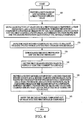
- FIG. 3 illustrates a flowchart of a method of manufacturing an electronic-charge-transferring device according to certain embodiments of the present invention.
- This method may start with step 200, which specifies that a charged species source 10 and a charged species drain 60 be provided.
- the source 10 and drain 60 can be micro-manufactured, though no particular size limitations are made on the source 10 and drain 60.
- Step 200 may also provide the source 10 and drain 60 to be in contact with a moveable component, such as, but not limited to, the plate 80 illustrated in FIG. 2.
- Step 210 specifies the manufacture of the moveable component for transferring charge to the charged species drain 60, a first protrusion 90 proximate to the moveable component, and a second protrusion 100 proximate to the moveable component, wherein the moveable component is positioned in close proximity to the charged species source 10, and wherein at least one of the moveable component, the first protrusion 90 and the second protrusion 100 is micro-manufactured.
- Step 210 may, according to certain embodiments, specify including a first material in the first protrusion 90 and a second material, different from the first material, in the second protrusion 100. Further, step 210 may specify including a third material, different from the first material and the second material, in the moveable component.
- Step 220 specifies that the first protrusion 90 and the second protrusion 100 be positioned in contact with the moveable component. In such embodiment, there is friction between the protrusions 90, 100 and the moveable component.
- Step 230 specifies that a device 70 be electrically connected to the charged species drain 60. Any device 70 is within the scope of the present invention, so long as the device 70 could benefit from the current of charged species flowing through the drain 60.
- FIG. 4 illustrates a flowchart of a method of transferring electric charge according to certain embodiments of the present invention.
- step 300 specifies that a first charged species source 10 and a first charged species drain 60 be provided.
- the source 10 and drain 60 may be micro-manufactured, although no particular size restrictions are placed on either the source 10 or the drain 60.
- Step 310 specifies micro-manufacture at least one of a first moveable component, a first protrusion 90, and a second protrusion 100, wherein the moveable component is positioned proximate to the first charged species source 10 and the first charged species drain 60, and wherein the first protrusion 90 and the second protrusion 100 each contact the first moveable component. Also, although step 310 specifies micro-manufacturing, nanometer-scaled manufacturing and larger-scaled manufacturing are also within the scope of certain embodiments of the present invention.
- Step 320 specifies moving the first moveable component relative to the first charged species source 10 and the first charged species drain 60.
- the moving step 320 includes translating the first moveable component relative to the first charged species source 10.
- the first moveable component may be rotated about a rotation axis 85.
- Step 330 specifies tribocharging the first protrusion 90 and the second protrusion 100.
- the first charged species drain 60 may be used to supply an electric current to a device 70.
- the device 70 may be any item that would benefit from being supplied from an electrical current.
- Step 350 then specifies providing a second moveable component, a second charged species source, and a second charged species drain, each positioned proximate to the second moveable component, and a third protrusion and a fourth protrusion, each positioned proximate the second moveable component, wherein the first charged species drain 60 and the second charged species drain are each electrically connected to a device 70.
- Step 360 then specifies moving the second moveable component out of phase with the first moveable component. In such a configuration, when a translating first moveable component is moving away from the first charged species drain 60, the second moveable component may move toward the second charged species drain, thereby providing the device 70 with a more steady electric current.
Landscapes
- Thin Film Transistor (AREA)
- Electrostatic Charge, Transfer And Separation In Electrography (AREA)
- Electrostatic Separation (AREA)
- Piezo-Electric Or Mechanical Vibrators, Or Delay Or Filter Circuits (AREA)
- Container, Conveyance, Adherence, Positioning, Of Wafer (AREA)
Abstract
Description
Claims (10)
- A method of transferring electric charge comprising:providing a first charged species source (10) and a first charged species drain (60);micro-manufacturing at least one of a first moveable component (80), a first protrusion (90), and a second protrusion (100), wherein the moveable component (80) is positioned proximate to the first charged species source (10) and the first charged species drain (60), and wherein the first protrusion (90) and the second protrusion (100) each contact the first moveable component (80); andmoving the first moveable component (80) relative to the first charged species source (10) and the first charged species drain (60).
- A method as claimed in claim 1, wherein the providing step comprises micro-manufacturing the first charged species source (10) and the first charged species drain (60).
- A method as claimed in claim 1 or 2, wherein the moving step comprises translating the first moveable component (80) relative to the first charged species source (60).
- A method as claimed in any preceding claim, wherein the moving step comprises rotating the first moveable component (80) about a rotation axis (85).
- A method as claimed in any preceding claim, further comprising tribocharging the first protrusion (90) and the second protrusion (100).
- A method as claim in any preceding claim, further comprising providing a second moveable component, a second charged species source and a second charged species drain, each positioned proximate to the second moveable component, and a third protrusion and a fourth protrusion, each positioned proximate the second moveable component, wherein the first charged species drain (60) and the second charged species drain are each electrically connected to a device (70).
- A method as claimed in claim 6, further comprising moving the second movable component out of phase with the first moveable component (80).
- A van de graaf device comprising:a moveable component (80);a charged species source (10) proximate to the moveable component (80);a charged species drain (60) proximate to the moveable component (80);a first protrusion (90) contacting the moveable component (80); anda second protrusion (100) contacting the moveable component (80), wherein at least one of the moveable component (80), the first protrusion (90) and the second protrusion (100) is micro-machined.
- A van de graaf device as claimed in claim 8, wherein the charged species source (10) and the charged species drain (60) are micro-machined.
- A van de graaf device as claimed in claim 8 or 9, wherein the first protrusion (90) comprises a material that can be tribocharged by a material comprised in the moveable component (80).
Applications Claiming Priority (2)
| Application Number | Priority Date | Filing Date | Title |
|---|---|---|---|
| US09/995,765 US6990732B2 (en) | 2001-11-29 | 2001-11-29 | Method of manufacturing a micrometer-scaled electronic-charge-transferring device |
| US995765 | 2001-11-29 |
Publications (2)
| Publication Number | Publication Date |
|---|---|
| EP1317055A2 true EP1317055A2 (en) | 2003-06-04 |
| EP1317055A3 EP1317055A3 (en) | 2004-09-08 |
Family
ID=25542185
Family Applications (1)
| Application Number | Title | Priority Date | Filing Date |
|---|---|---|---|
| EP02258190A Withdrawn EP1317055A3 (en) | 2001-11-29 | 2002-11-28 | Van de Graaf MEMS electrostatic generator |
Country Status (4)
| Country | Link |
|---|---|
| US (2) | US6990732B2 (en) |
| EP (1) | EP1317055A3 (en) |
| JP (1) | JP2003230287A (en) |
| CN (1) | CN1421988B (en) |
Families Citing this family (5)
| Publication number | Priority date | Publication date | Assignee | Title |
|---|---|---|---|---|
| US20120056505A1 (en) * | 2010-09-07 | 2012-03-08 | Victor Mayorkis | Electrostatic generating apparatus for generating an electrostatic charge |
| CN103780122B (en) * | 2013-02-01 | 2015-12-09 | 北京纳米能源与系统研究所 | A sliding friction nanogenerator set |
| CN103780124B (en) * | 2013-03-12 | 2015-12-09 | 北京纳米能源与系统研究所 | A sliding friction nanogenerator set |
| CN103780131B (en) * | 2013-07-12 | 2015-11-25 | 北京纳米能源与系统研究所 | A kind of friction generator |
| CN105702283B (en) * | 2014-11-27 | 2018-08-10 | 北京纳米能源与系统研究所 | Movement locus memory storage based on triboelectrification and accumulating method |
Family Cites Families (15)
| Publication number | Priority date | Publication date | Assignee | Title |
|---|---|---|---|---|
| GB719687A (en) | 1951-11-21 | 1954-12-08 | Noel Joseph Felici | Improvements in or relating to electrostatic machines |
| DE1044941B (en) | 1953-11-06 | 1958-11-27 | Mach Electrostatiques S A M E | Device for the exchange of electricity in electrostatic machines |
| US2831988A (en) | 1956-02-13 | 1958-04-22 | Sames Mach Electrostat | Means for excitation and commutation of electrostatic machines |
| US3614481A (en) * | 1969-06-16 | 1971-10-19 | Robert B Halliday | Electrostatic generator |
| US4014605A (en) * | 1973-12-03 | 1977-03-29 | Xerox Corporation | Transfer system with tailored illumination |
| US4004175A (en) * | 1974-12-16 | 1977-01-18 | The United States Of America As Represented By The Secretary Of The Army | High voltage particle accelerator utilizing polycrystalline ferroelectric ceramic material |
| US4440638A (en) * | 1982-02-16 | 1984-04-03 | U.T. Board Of Regents | Surface field-effect device for manipulation of charged species |
| GB8504481D0 (en) * | 1985-02-21 | 1985-03-27 | Soszek P | Circuitry |
| JPS627378A (en) * | 1985-06-11 | 1987-01-14 | Nippon Fuijitetsuku Kiki Kk | Voltage doubler electrostatic high-tension generating set |
| US4943750A (en) * | 1987-05-20 | 1990-07-24 | Massachusetts Institute Of Technology | Electrostatic micromotor |
| US5083167A (en) * | 1989-05-09 | 1992-01-21 | Canon Kabushiki Kaisha | Image forming apparatus for supplying different amounts of electric charge to an end portion of a transfer material |
| US6104107A (en) * | 1992-05-08 | 2000-08-15 | Uniline Limited | Method and apparatus for single line electrical transmission |
| US5557596A (en) * | 1995-03-20 | 1996-09-17 | Gibson; Gary | Ultra-high density storage device |
| US5829598A (en) * | 1995-04-28 | 1998-11-03 | Separation Technologies, Inc. | Method and apparatus for electrostatic separation |
| TW374211B (en) * | 1995-08-03 | 1999-11-11 | Ibm | Machine structures fabricated of multiple microstructure layers |
-
2001
- 2001-11-29 US US09/995,765 patent/US6990732B2/en not_active Expired - Fee Related
-
2002
- 2002-11-25 JP JP2002341035A patent/JP2003230287A/en active Pending
- 2002-11-28 EP EP02258190A patent/EP1317055A3/en not_active Withdrawn
- 2002-11-28 CN CN021527911A patent/CN1421988B/en not_active Expired - Fee Related
-
2003
- 2003-06-10 US US10/459,324 patent/US6978537B2/en not_active Expired - Fee Related
Also Published As
| Publication number | Publication date |
|---|---|
| CN1421988B (en) | 2010-05-26 |
| US6978537B2 (en) | 2005-12-27 |
| JP2003230287A (en) | 2003-08-15 |
| US20030200651A1 (en) | 2003-10-30 |
| US6990732B2 (en) | 2006-01-31 |
| CN1421988A (en) | 2003-06-04 |
| EP1317055A3 (en) | 2004-09-08 |
| US20030099080A1 (en) | 2003-05-29 |
Similar Documents
| Publication | Publication Date | Title |
|---|---|---|
| Park et al. | Nanoscale, electrified liquid jets for high-resolution printing of charge | |
| US20190115132A1 (en) | Levitated Motor-Actuator with Parallel Dipole Line Trap System | |
| US6990732B2 (en) | Method of manufacturing a micrometer-scaled electronic-charge-transferring device | |
| KR20130143021A (en) | Ion generation device | |
| US6636717B2 (en) | Developing device including first and second developer carrying devices with insufficiently-charged developer control feature | |
| EP0461507A2 (en) | Meterless single component development | |
| JP2004117419A5 (en) | ||
| JP2003275656A (en) | Electrostatic powder coating equipment | |
| JPH0519632A (en) | Developing device | |
| US5602632A (en) | Belt applicator for developing ink or toner on a print member | |
| JP2002214910A (en) | Developing device and image forming apparatus provided with the same | |
| JPS62168175A (en) | Developing device | |
| JP2001018440A (en) | Particle charging device and developing device | |
| JP2003093986A (en) | Cleaning method and cleaning device | |
| JPH04335682A (en) | Image forming device | |
| JPH05181392A (en) | Electrophotographic device | |
| JP2002346997A (en) | Microactuator and its application | |
| JP2005258345A (en) | Developing apparatus and developing method | |
| EP2159648B1 (en) | A method to charge toner for electrophotography using carbon nanotubes or other nanostructures | |
| JPH0313974A (en) | Electrophotographic developing device | |
| JPH0610372Y2 (en) | Development device | |
| JPH04116679A (en) | Device for recovering developer | |
| JP2006317791A (en) | Method and apparatus for separating and collecting developer for electrophotography or coating agent for electrostatic coating | |
| JP2004126163A (en) | Charging device for image forming apparatus | |
| JPH06348107A (en) | Image forming device |
Legal Events
| Date | Code | Title | Description |
|---|---|---|---|
| PUAI | Public reference made under article 153(3) epc to a published international application that has entered the european phase |
Free format text: ORIGINAL CODE: 0009012 |
|
| AK | Designated contracting states |
Designated state(s): AT BE BG CH CY CZ DE DK EE ES FI FR GB GR IE IT LI LU MC NL PT SE SK TR |
|
| AX | Request for extension of the european patent |
Extension state: AL LT LV MK RO SI |
|
| PUAL | Search report despatched |
Free format text: ORIGINAL CODE: 0009013 |
|
| AK | Designated contracting states |
Kind code of ref document: A3 Designated state(s): AT BE BG CH CY CZ DE DK EE ES FI FR GB GR IE IT LI LU MC NL PT SE SK TR |
|
| AX | Request for extension of the european patent |
Extension state: AL LT LV MK RO SI |
|
| RIC1 | Information provided on ipc code assigned before grant |
Ipc: 7H 02N 1/10 B Ipc: 7H 02N 1/12 A |
|
| 17P | Request for examination filed |
Effective date: 20050228 |
|
| AKX | Designation fees paid |
Designated state(s): DE GB |
|
| STAA | Information on the status of an ep patent application or granted ep patent |
Free format text: STATUS: THE APPLICATION HAS BEEN WITHDRAWN |
|
| 18W | Application withdrawn |
Effective date: 20060203 |