EP1316954A2 - Recording and regeneration apparatus and data erasure method for use in the recording and regeneration apparatus - Google Patents
Recording and regeneration apparatus and data erasure method for use in the recording and regeneration apparatus Download PDFInfo
- Publication number
- EP1316954A2 EP1316954A2 EP02020062A EP02020062A EP1316954A2 EP 1316954 A2 EP1316954 A2 EP 1316954A2 EP 02020062 A EP02020062 A EP 02020062A EP 02020062 A EP02020062 A EP 02020062A EP 1316954 A2 EP1316954 A2 EP 1316954A2
- Authority
- EP
- European Patent Office
- Prior art keywords
- data
- erasure
- recording
- disk
- disk medium
- Prior art date
- Legal status (The legal status is an assumption and is not a legal conclusion. Google has not performed a legal analysis and makes no representation as to the accuracy of the status listed.)
- Withdrawn
Links
- 230000008929 regeneration Effects 0.000 title claims abstract description 22
- 238000011069 regeneration method Methods 0.000 title claims abstract description 22
- 238000000034 method Methods 0.000 title claims description 19
- 238000004590 computer program Methods 0.000 claims description 6
- 230000004044 response Effects 0.000 abstract description 5
- 230000006870 function Effects 0.000 description 3
- 238000010586 diagram Methods 0.000 description 2
- 238000002360 preparation method Methods 0.000 description 2
- 230000010365 information processing Effects 0.000 description 1
- 230000003287 optical effect Effects 0.000 description 1
- 230000000007 visual effect Effects 0.000 description 1
Images


Classifications
-
- G—PHYSICS
- G11—INFORMATION STORAGE
- G11B—INFORMATION STORAGE BASED ON RELATIVE MOVEMENT BETWEEN RECORD CARRIER AND TRANSDUCER
- G11B19/00—Driving, starting, stopping record carriers not specifically of filamentary or web form, or of supports therefor; Control thereof; Control of operating function ; Driving both disc and head
- G11B19/02—Control of operating function, e.g. switching from recording to reproducing
Definitions
- the present invention relates to a recording and regeneration apparatus and a data erasure method for use in the recording and regeneration apparatus, and more particularly to a technique for securely erasing data from a recording and regeneration apparatus.
- disk drive In general, in information processing apparatuses such as personal computers, a hard disk drive (hereinafter referred to simply as a "disk drive”) is used as an external storage device.
- a disk drive is a device that writes to and reads from a disk medium.
- small and thin-type disk drives have been developed.
- disk drives are used as storage devices in portable electronic apparatuses such as portable computers and PDAs (Personal Digital Assistants).
- Disk drives are also used to record audio/visual ("AV") data in various types of Digital AV apparatuses such as, for example, digital TVs and digital VCRs.
- AV Audio/visual
- a medium a floppy disk, for example
- a dedicated data erasure program capable of reliably erasing all the data stored on a disk drive.
- a personal computer executes a dedicated data erasure program from a floppy disk, thereby erasing the data on the disk.
- Japanese Patent Laid-Open No. 6-150326 discloses a disk recording and regeneration device having a data erasure instruction key. If the data erasure instruction key is operated by a user while power is applied to the device, the device will erase data on the disk.
- the device disclosed in the above-named patent may be discarded or resold with data remaining on the disk.
- power will necessarily be removed from the device.
- the data erasure instruction key be operated (for example, by a new owner) once power has been reapplied to the device. Therefore, there remains a danger of disclosure to third parties of the data stored on the disk.
- a recording and regeneration device for reliably erasing data stored on a disk medium which does not require a particular working environment such as a host system or a medium that stores a dedicated data erasure program.
- the recording and regeneration device comprises a disk medium on which data is recorded; a switching means for switching to an erasure instruction generating position for generating an erasure instruction, the erasure instruction generating position being maintained after the switching means is switched thereto; and a control means having an erasure mode for executing, in response to the erasure instruction, data erasure processing for erasing data recorded on the disk medium.
- the recording and regeneration device comprises a disk medium on which data is recorded; a control means having an erasure mode for executing, in response to an erasure instruction, data erasure processing for erasing data recorded on the disk medium; and switching means operable for switching between a first position for generating the erasure instruction and a second position for not generating the erasure instruction; wherein while the switching means is maintained in the first position, the control means remains in the erasure mode.
- the recording and regeneration device comprises a disk medium on which data is recorded, an on-board memory, on-board means for generating an erasure instruction and on-board control means for executing, when the erasure instruction is generated, a computer program stored in the on-board memory, the computer program providing data erasure processing to erase data recorded on the disk medium.
- the erasure instruction designates an erasure mode of the on-board control means.
- the on-board control means assumes one of a normal operation mode when the erasure instruction is not generated and an erasure mode when the erasure instruction is generated, the on-board control means executing, in the normal operation mode, at least one of writing of data to the disk medium and reading of data from the disk medium in accordance with a command from a host system, and the on-board control means executing, in the erasure mode, the data erasure processing.
- the on-board control means may determine, upon application of power to the recording and regeneration device, whether or not the erasure instruction is generated.
- the on-board control means may comprise an on-board processor.
- the on-board processor executes, when the erasure instruction is generated, a data erasure program stored in a non-volatile on-board memory, the data erasure program for erasing data recorded on the disk medium.
- a method for erasing data recorded on a disk medium in a recording and regeneration device.
- the method comprises providing on a housing of the recording and regeneration apparatus a switching means which generates an erasure instruction when the switching means is operated, providing an on-board memory and providing on-board control means for executing, when the erasure instruction is generated, a computer program stored in the on-board memory, the computer program providing data erasure processing to erase data recorded on the disk medium.
- the switching means may comprise a jumper switch or a jumper pin.
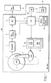
- FIG. 1 is a block diagram illustrating the configuration of a disk drive according to an embodiment of the invention.
- a disk drive 100 is used as, for example, a storage device for a host system 20 such as a computer. In the description below, it is supposed that the disk drive 100 is a hard disk drive.
- the disk drive 100 is an electromechanical device for controlling the rotation of a disk medium 1 (hereinafter referred to simply as a "disk”) as a magnetic recording medium, thereby reading and writing data from and to the disk 1.
- the housing of the disk drive 100 comprises a base unit (not shown) on which the components of the disk drive 100 are mounted, and a top cover (not shown) joined with the base unit to form the housing of the disk drive 100.
- the housing houses the disk 1, a magnetic head 2, spindle motor (SPM) 3, actuator 4, voice coil motor (VCM) 5 and motor driver IC 6.
- SPM spindle motor
- VCM voice coil motor
- the housing of the disk drive 100 can be designed to mount one or more disks 1, it is supposed here, for the sake of explanation, that only one disk 1 is mounted.
- the disk 1 is rotatably mounted on the base unit.
- a surface of the disk 1 has a data region for magnetically storing data.
- the spindle motor (SPM) 3 is provided to drive and rotate the disk 1. When the disk drive 100 operates, the disk 1 is rotated at a predetermined speed by the spindle motor (SPM) 3.
- the magnetic head 2 is mounted on the free end of the actuator 4 that is driven and rotated by the voice coil motor (VCM) 5, and reads and writes data from and to the disk 1.
- VCM voice coil motor
- the actuator 4 is used to position the magnetic head 2 to a target position on the disk 1.
- the magnetic head 2 comprises a slider, and a write head element and read head element mounted on the slider.
- the write head element is used to magnetically write data to the disk 1, while the read head element is used to magnetically read data from the disk 1.
- the motor driver IC 6 comprises a VCM driver 60 for supplying a driving current to the voice coil motor (VCM) 5, and an SMP driver 61 for supplying a driving current to the spindle motor (SPM) 3.
- the voice coil motor (VCM) 5 is supplied with a driving current from the VCM driver 60 included in the motor drive IC 6.
- the motor drive IC 6 is controlled by a CPU 10.
- the housing of the disk drive 100 houses a preamplifier circuit 7, R/W channel 8, disk controller (HDC) 9, CPU 10, memory 11 and power supply circuit 12.
- the preamplifier circuit 7 has a read amplifier and write amplifier.
- the read amplifier amplifies a read data signal output from the read head element of the magnetic head 2.
- the write amplifier converts a write data signal input from the R/W channel 8 into a write current signal and supplies the resultant signal to the write head of the magnetic head 2.
- the R/W channel 8 is a signal processing IC for processing a read/write data signal (including a servo data signal).
- the disk controller (HDC) 9 has an interface function for interfacing the disk drive 100 and the host system 20 (e.g., a personal computer, digital device, etc.).
- the CPU 10 is a processor device for controlling the operation of the disk drive 100, and controls the servo system, normal read/write operations, and data erasure processing, etc.
- the memory 11 may comprise a flash memory as a non-volatile memory.
- the memory 11 may also comprise RAM, ROM, etc.
- the programs stored on-board the disk drive 100 in the memory 11 include a data erasure program 110 for executing the aforementioned data erasure processing.
- the data erasure program 110 may, as an example, be stored in the flash memory.
- the data erasure program 110 is a program for causing the disk drive 100 itself to automatically execute a data erasure operation for erasing all data recorded on the data region of the disk 1.
- the CPU 10 executes the data erasure program 110. This means that the disk drive 100 itself can execute the data erasure operation for erasing all data recorded on the disk 1, without the control of the host system 20.
- the power supply circuit 12 provides a power supply voltage necessary to operate each component of the disk drive 100, using externally supplied power.
- the housing of the disk drive 100 has a data erasure switch 13.
- the data erasure switch 13 is an operation switch for instructing the disk drive 100 to execute the data erasure operation (e.g., a jumper switch, jumper pin, DIP switch, toggle switch, or any other suitable switching device that may be configured by a user such that a position of the switching device is maintained (i.e., "remembered") after being configured. While the switching device is maintained in this position, the disk drive 100 is instructed to execute the data erasure operation).
- the data erasure switch 13 In response to the operation of the data erasure switch 13 by a user, the data erasure switch 13 generates an erasure instruction signal ES for designating an operation mode of the disk drive to be an erasure mode for executing the data erasure operation.
- the erasure switch 13 Once the erasure switch 13 has been operated (for example, once a jumper switch or jumper pin has been configured by the user), the operation mode of the disk drive will remain in the erasure mode until the configuration of the erasure switch 13 is changed, i.e., the operation mode of the disk drive is maintained.
- the CPU 10 assumes the erasure mode and executes the data erasure program 110.
- the data erasure operation for erasing all data recorded on the disk 1 is automatically executed without any control of the host system 20.
- FIG. 2 is a view illustrating the outward appearance of the disk drive 100, according to embodiments of the present invention.
- the data erasure switch 13 is provided on the bottom of the housing of the disk drive 100, i.e., on the reverse surface 101 of the base unit, so that a user can operate it.
- An interface connector 14 to be connected to the host system 20 is provided at an end of the housing of the disk drive 100.
- the connector 14 has a power supply pin 140 as well as various signal pins. When the disk drive 100 is connected to the host system 20, the disk drive 100 is supplied with power from the host system 20 via the power supply pin 140.
- the disk drive 100 is used housed in the main unit of the host system 20 such as a personal computer. Suppose here, for example, that the disk drive 100 will be disposed of.
- the disk drive 100 is detached from the main unit of the host system 20.
- an external power supply such as a battery 200 (or an AC adapter (not shown)) is connected to the power supply pin 140 of the disk drive 100, thereby supplying the disk drive 100 with power (PS) for driving it.
- an indicator 201 formed of, for example, a light emitting diode ("LED") used to indicate the start of data erasure processing can be connected to a predetermined signal output pin 141 of the connector 14.
- the CPU 10 outputs a control signal for lighting the indicator 201 via the output terminal 141, while the data erasure operation is executed.
- LED light emitting diode
- FIG. 3 illustrates a procedure for the data erasure operation, according to embodiments of the present invention.
- the disk drive 100 When the battery 200 is connected to power supply pin 140 of the disk drive 100, the disk drive 100 is powered on.
- the CPU 10 executes initialization processing for various types of preparation processing necessary to activate the disk drive 100 (step S1). After that, the CPU 10 determines whether or not an instruction to enter the erasure mode has been issued (i.e., whether or not erasure switch 13 has been operated) (step S2).
- the switch 13 In this state, if a user has operated the data erasure switch 13 of the disk drive 100, the switch 13 generates the erasure instruction signal ES. Upon generation of the erasure instruction signal ES, the CPU 10 determines that an instruction to enter the erasure mode has been issued (the answer at step S2 is YES). On the other hand, if the erasure instruction signal ES is not generated, the CPU 10 enters into a normal operation mode. Thus, the CPU 10 determines whether or not the switch 13 is operated when the disk drive 100 is powered on through use of the battery 200 or other power source and assumes the normal operation mode or the erasure mode in accordance with the determination result.
- the CPU 10 executes a data writing operation and a data reading operation in accordance with commands from the host system 20, (i.e., if the disk drive 100 is still attached to the main unit of the host system 20).
- the CPU 10 executes the data erasure program 110, thereby executing the following processing independently of the host system 20.
- the CPU 10 starts preparation processing for executing the data erasure operation (step S3). Specifically, at the step S3, the CPU 10 drives the spindle motor (SPM) 3 via the SPM driver 61 to rotate the disk 1. Further, the CPU 10 outputs a control signal for controlling the indicator 201 via the output pin 141 of the connector 14, thereby lighting the indicator 201. From the lighting of the indicator 201, the user can recognize that the data erasure function of the disk drive 100 has been validated.
- SPM spindle motor
- the CPU 10 drives the actuator 4 via the VCM driver 60, thereby starting the data erasure processing for erasing all data recorded on the data region of the disk 1 (i.e., all user data including data and programs, such as the operating system and application programs) (step S4).
- the CPU 10 may execute a write operation (over-writing) for sequentially writing random data patterns to all data sectors on the data region of the disk 1, using the R/W channel 8 and magnetic head 2.
- a write operation over-writing
- data recorded on all the data sectors of the disk 1 is reliably erased.
- data on all the data sectors of the disk 1 is replaced with meaningless data, which means that the original user data is reliably and securely erased. The original user data can no longer be restored.
- formatting processing for executing physical format processing may be executed instead of writing random data patterns. This processing also makes it difficult to restore the previous user data.
- Servo data necessary for servo control is also recorded on the data region of the disk 1.
- the data region of the disk 1 comprises a plurality of data sectors for storing user data, and a plurality of servo sectors storing servo data used for positioning the magnetic head 2.
- the servo data is excluded from the to-be-erased targets, (i.e., the servo data is preserved on the disk 1).
- random data patterns are written to the data sectors, while no such writing is executed on the servo sectors.
- the disk drive 100 can again be used as a storage device for the host system 20 or another system only if the disk 1 of the disk drive 100 is formatted.
- the CPU 10 stops the operation of the disk drive 100 (step S6). Specifically, the CPU 10 stops the rotation of the spindle motor (SPM) 3 via the SPM driver 61, and switches off the indicator 201. From the switching off of the indicator 201, the user recognizes that the data erasure processing of the disk drive 100 is completed.
- SPM spindle motor
- the disk drive 100 will automatically execute the data erasure processing. Consequently, the disk drive 100 itself can erase the data recorded on the disk 1, without requiring a special working environment such as a host system or a medium that stores the data erasure program.
- the indicator 201 is not an essential element.
- the user can recognize the completion of the data erasure processing simply by measuring the time period elapsing from the start of data erasure processing.
- the switch 13 has been operated (i.e., configured)
- the user may mark the beginning of data erasure processing as the point in time when power is applied to the disk drive.
- the disk drive of the embodiment is assumed to be a hard disk drive, it may be another type of disk drive such as, but not limited to, a rewritable optical disk drive.
- a hard disk drive that does not record servo data, it may be necessary, of course, to execute a process for erasing all data recorded on the disk (the process may include format processing and/or random-pattern-writing processing).
- the switch 13 is provided on the housing of the disk drive 100.
- the erasure instruction signal ES designating the erasure mode may be provided to the CPU 10, in response to a dedicated signal or command input from outside the disk drive 100 via a predetermined pin or pins of the connector 14.
- the dedicated command signal may be input to a predetermined signal input pin 143 of the connector 14, as shown in FIG. 2.
- the erasure mode may be configured by the user by setting an erasure status indicator in a memory, for example memory 11.
- the erasure status indicator may be, for example, a status bit or status word stored in an address location of the memory.
- the CPU 10 may check the erasure status indicator and may execute a data erasure program stored in the memory for erasing the data when the erasure status indicator indicates an erasure mode of the CPU 10.
Landscapes
- Storage Device Security (AREA)
- Signal Processing For Digital Recording And Reproducing (AREA)
Abstract
Description
Claims (11)
- A recording and regeneration apparatus, characterized by comprising:a disk medium (1) on which data is recorded;a switch (13) operable for generating an erasure instruction;a memory (11); anda processor (10) for executing a data erasure program permanently stored in the memory (11) for erasing data recorded on the disk medium (1) when the erasure instruction is generated.
- The recording and regeneration apparatus according to claim 1, characterized in that the on-board processor (10) determines whether or not the erasure instruction is generated upon application of power to the recording and regeneration apparatus.
- The recording and regeneration apparatus according to claim 1, characterized in that the switch (13) is at least one of a jumper switch, a jumper pin, a DIP switch and a toggle switch.
- A method of erasing data recorded on a disk medium (1) in a recording and regeneration apparatus, characterized by comprising:providing a switching means (13) which generates an erasure instruction when the switching means (13) is operated;providing a memory (11); andproviding control means (10) for executing, when the erasure instruction is generated, a computer program stored in the memory (11), the computer program providing data erasure processing to erase data recorded on the disk medium (1).
- The method according to claim 4, characterized in that the erasure instruction designates an erasure mode of the control means (10).
- The method according to claim 4, characterized in that the control means (10) determines whether or not the erasure instruction is generated upon application of power to the recording and regeneration apparatus.
- The method according to claim 4, characterized in that the switching means (13) comprises at least one of a jumper switch, a jumper pin, a DIP switch and a toggle switch.
- The method according to claim 4, characterized in that the control means (10) assumes one of a normal operation mode when the erasure instruction is not generated and an erasure mode when the erasure instruction is generated, the control means (10) executing, in the normal operation mode, at least one of writing of data to the disk medium (1) and reading of data from the disk medium (1) in accordance with a command from a host system, and the means (10) executing, in the erasure mode, the data erasure processing.
- The method according to claim 4, characterized by further comprising providing means (201) for indicating whether the data erasure processing is executed.
- The method according to claim 9, characterized in that the indicating means (201) comprises a light emitting diode.
- The method according to claim 4, characterized in that a surface of the disk medium (1) has a data region which records data, the data region including a plurality of data sectors which store user data, and a plurality of servo sectors which store servo data, and wherein the control means (10) includes means for erasing the user data of all the data sectors, while preserving the servo data on the disk medium (1).
Applications Claiming Priority (2)
| Application Number | Priority Date | Filing Date | Title |
|---|---|---|---|
| JP2001367250A JP3673213B2 (en) | 2001-11-30 | 2001-11-30 | Disk storage device and data erasing method applied to the same |
| JP2001367250 | 2001-11-30 |
Publications (2)
| Publication Number | Publication Date |
|---|---|
| EP1316954A2 true EP1316954A2 (en) | 2003-06-04 |
| EP1316954A3 EP1316954A3 (en) | 2004-05-26 |
Family
ID=19177028
Family Applications (1)
| Application Number | Title | Priority Date | Filing Date |
|---|---|---|---|
| EP02020062A Withdrawn EP1316954A3 (en) | 2001-11-30 | 2002-09-06 | Recording and regeneration apparatus and data erasure method for use in the recording and regeneration apparatus |
Country Status (3)
| Country | Link |
|---|---|
| US (1) | US20030103288A1 (en) |
| EP (1) | EP1316954A3 (en) |
| JP (1) | JP3673213B2 (en) |
Families Citing this family (19)
| Publication number | Priority date | Publication date | Assignee | Title |
|---|---|---|---|---|
| US7483342B2 (en) * | 2003-02-28 | 2009-01-27 | Dell Products L.P. | Method and system for reconditioning optical storage media to write updated information |
| JP4651291B2 (en) * | 2004-03-12 | 2011-03-16 | 株式会社リコー | Information processing apparatus, image processing apparatus, and image forming apparatus |
| US20050228938A1 (en) * | 2004-04-07 | 2005-10-13 | Rajendra Khare | Method and system for secure erasure of information in non-volatile memory in an electronic device |
| JP2006031268A (en) * | 2004-07-14 | 2006-02-02 | Sharp Corp | Information processing apparatus and storage control apparatus |
| US7536502B2 (en) | 2004-07-23 | 2009-05-19 | Funai Electric Co., Ltd. | Controller device to be connected to IEEE 1394 serial bus |
| EP1659474A1 (en) * | 2004-11-15 | 2006-05-24 | Thomson Licensing | Method and USB flash drive for protecting private content stored in the USB flash drive |
| US20060120235A1 (en) * | 2004-12-06 | 2006-06-08 | Teac Aerospace Technologies | System and method of erasing non-volatile recording media |
| JP2008523468A (en) * | 2004-12-06 | 2008-07-03 | テイアック エアロスペース テクノロジーズ インコーポレイテッド | Non-volatile recording medium erasing system and method |
| JP4653497B2 (en) * | 2005-01-12 | 2011-03-16 | 株式会社アイ・オー・データ機器 | Portable storage device |
| US7739462B2 (en) * | 2005-02-23 | 2010-06-15 | International Business Machines Corporation | Policy based data shredding for storage controller |
| JP2009512968A (en) * | 2005-10-20 | 2009-03-26 | エンスコンス データ テクノロジー インコーポレイテッド | Hard drive eraser |
| JP2008021344A (en) * | 2006-07-11 | 2008-01-31 | Hitachi Ltd | Hard disk device and data erasing method |
| DE102008012199A1 (en) | 2008-03-03 | 2009-09-17 | Weber, Christof | Data media e.g. hard disk, erasing device, has insert elements provided for receiving data media in fiber channel and small computer system interface formats, and controllers for simultaneous controlling of different data medium types |
| JP4893856B2 (en) | 2008-09-12 | 2012-03-07 | 富士通株式会社 | Storage device mounting frame, storage expansion device, and storage device control method |
| JP4945655B2 (en) * | 2010-04-13 | 2012-06-06 | 株式会社リコー | Information processing apparatus, image processing apparatus, information processing method, computer program, and recording medium |
| US9530436B1 (en) | 2010-08-12 | 2016-12-27 | Western Digital Technologies, Inc. | Methods and systems for providing data security in data storage devices |
| JP5959238B2 (en) * | 2012-03-06 | 2016-08-02 | 富士通テン株式会社 | Vehicle control apparatus and vehicle control method |
| JP6598453B2 (en) | 2014-11-12 | 2019-10-30 | キヤノン株式会社 | Information processing apparatus, control method, and program |
| US10656854B1 (en) * | 2019-10-22 | 2020-05-19 | Apricorn | Method and portable storage device with internal controller that can self-verify the device and self-convert the device from current mode to renewed mode without communicating with host |
Family Cites Families (11)
| Publication number | Priority date | Publication date | Assignee | Title |
|---|---|---|---|---|
| GB2227107B (en) * | 1978-10-14 | 1990-10-10 | Emi Ltd | Equipment for electronically storing data |
| US4851936A (en) * | 1986-08-15 | 1989-07-25 | Fuji Photo Film Co., Ltd. | Erasing method for erasing information corrected on a magnetic recording medium |
| JP2830149B2 (en) * | 1989-08-31 | 1998-12-02 | キヤノン株式会社 | Erasing device |
| JP3305737B2 (en) * | 1991-11-27 | 2002-07-24 | 富士通株式会社 | Confidential information management method for information processing equipment |
| WO1997004395A1 (en) * | 1995-07-20 | 1997-02-06 | Dallas Semiconductor Corporation | Method and apparatus for encryption key creation |
| JP4033310B2 (en) * | 1997-12-16 | 2008-01-16 | 富士通株式会社 | Auxiliary storage device for information equipment and information equipment |
| DE19942141C2 (en) * | 1998-10-06 | 2003-12-04 | Ricoh Kk | Method and device for deleting data after a forgery |
| US6377526B1 (en) * | 1999-04-01 | 2002-04-23 | Plasmon Ide, Inc. | Erasable WORM optical disk and method of writing thereto multiple times |
| US20010025343A1 (en) * | 2000-03-27 | 2001-09-27 | Roy Chrisop | Random bit mask generation for obscuring data on nonvolatile memory device |
| JP2002245635A (en) * | 2001-02-21 | 2002-08-30 | Matsushita Electric Ind Co Ltd | Optical disk data erasing device and optical disk data erasing method |
| US6731447B2 (en) * | 2001-06-04 | 2004-05-04 | Xerox Corporation | Secure data file erasure |
-
2001
- 2001-11-30 JP JP2001367250A patent/JP3673213B2/en not_active Expired - Fee Related
-
2002
- 2002-09-05 US US10/235,416 patent/US20030103288A1/en not_active Abandoned
- 2002-09-06 EP EP02020062A patent/EP1316954A3/en not_active Withdrawn
Also Published As
| Publication number | Publication date |
|---|---|
| EP1316954A3 (en) | 2004-05-26 |
| US20030103288A1 (en) | 2003-06-05 |
| JP2003167681A (en) | 2003-06-13 |
| JP3673213B2 (en) | 2005-07-20 |
Similar Documents
| Publication | Publication Date | Title |
|---|---|---|
| US20030103288A1 (en) | Recording and regeneration apparatus and data erasure method for use in the recording and regeneration apparatus | |
| US7934030B1 (en) | Disk drive comprising code segments for interfacing with a component such as a read channel | |
| US8412876B2 (en) | Storage device with multiple storage units and control method thereof | |
| US5717887A (en) | System for the automatic substitution of control firmware embedded in a removable disk drive | |
| JP2008523468A (en) | Non-volatile recording medium erasing system and method | |
| JP2005216476A (en) | Automatic data update method in data storage system and disk drive using the same | |
| US7490357B2 (en) | Data protection in data storage system | |
| JPWO2004109676A1 (en) | Information recording / reproducing apparatus and method | |
| KR19980066323A (en) | Initializing method of hard disk drive and copying device therefor | |
| JPH0546001B2 (en) | ||
| US20080010504A1 (en) | Method and apparatus for storing data in a disk drive with nonvolatile memory | |
| KR100630713B1 (en) | Spindle Motor Starting Current Control Method and Disk Drive Using the Same | |
| US7389378B2 (en) | Write processing method for stream type commands and medium storage apparatus | |
| JPH0714290A (en) | Operating and control method of disk apparatus | |
| US20150205543A1 (en) | Storage device and data storing method | |
| JP2006172533A (en) | Servo information writing method and apparatus | |
| KR100417226B1 (en) | Method for realizing scam protocol of hard disk drive | |
| JPH09312084A (en) | Information recording device | |
| JP2007200458A (en) | Magnetic disk drive and data erasing method | |
| JPH065008A (en) | Testing method for magnetic disk device | |
| JP2992837B2 (en) | Magnetic storage device | |
| JP2006099856A (en) | Recording media drive | |
| JPH08194903A (en) | Data writing method and floppy disc apparatus utilizing the method | |
| JP2003141702A (en) | Disk storage and write control method | |
| US20040240329A1 (en) | Optical disk recording apparatus including an operating face panel capable of visual indication of recording status |
Legal Events
| Date | Code | Title | Description |
|---|---|---|---|
| PUAI | Public reference made under article 153(3) epc to a published international application that has entered the european phase |
Free format text: ORIGINAL CODE: 0009012 |
|
| 17P | Request for examination filed |
Effective date: 20020906 |
|
| AK | Designated contracting states |
Designated state(s): AT BE BG CH CY CZ DE DK EE ES FI FR GB GR IE IT LI LU MC NL PT SE SK TR |
|
| AX | Request for extension of the european patent |
Extension state: AL LT LV MK RO SI |
|
| PUAL | Search report despatched |
Free format text: ORIGINAL CODE: 0009013 |
|
| AK | Designated contracting states |
Kind code of ref document: A3 Designated state(s): AT BE BG CH CY CZ DE DK EE ES FI FR GB GR IE IT LI LU MC NL PT SE SK TR |
|
| AX | Request for extension of the european patent |
Extension state: AL LT LV MK RO SI |
|
| AKX | Designation fees paid |
Designated state(s): DE FR GB |
|
| STAA | Information on the status of an ep patent application or granted ep patent |
Free format text: STATUS: THE APPLICATION IS DEEMED TO BE WITHDRAWN |
|
| 18D | Application deemed to be withdrawn |
Effective date: 20060607 |