EP1316890A2 - Computer system with multiple system controllers - Google Patents
Computer system with multiple system controllers Download PDFInfo
- Publication number
- EP1316890A2 EP1316890A2 EP02258233A EP02258233A EP1316890A2 EP 1316890 A2 EP1316890 A2 EP 1316890A2 EP 02258233 A EP02258233 A EP 02258233A EP 02258233 A EP02258233 A EP 02258233A EP 1316890 A2 EP1316890 A2 EP 1316890A2
- Authority
- EP
- European Patent Office
- Prior art keywords
- system controller
- primary
- controller
- controllers
- computer system
- Prior art date
- Legal status (The legal status is an assumption and is not a legal conclusion. Google has not performed a legal analysis and makes no representation as to the accuracy of the status listed.)
- Withdrawn
Links
Images



Classifications
-
- G—PHYSICS
- G06—COMPUTING OR CALCULATING; COUNTING
- G06F—ELECTRIC DIGITAL DATA PROCESSING
- G06F11/00—Error detection; Error correction; Monitoring
- G06F11/07—Responding to the occurrence of a fault, e.g. fault tolerance
- G06F11/16—Error detection or correction of the data by redundancy in hardware
- G06F11/20—Error detection or correction of the data by redundancy in hardware using active fault-masking, e.g. by switching out faulty elements or by switching in spare elements
- G06F11/2097—Error detection or correction of the data by redundancy in hardware using active fault-masking, e.g. by switching out faulty elements or by switching in spare elements maintaining the standby controller/processing unit updated
-
- G—PHYSICS
- G06—COMPUTING OR CALCULATING; COUNTING
- G06F—ELECTRIC DIGITAL DATA PROCESSING
- G06F11/00—Error detection; Error correction; Monitoring
- G06F11/07—Responding to the occurrence of a fault, e.g. fault tolerance
- G06F11/16—Error detection or correction of the data by redundancy in hardware
- G06F11/20—Error detection or correction of the data by redundancy in hardware using active fault-masking, e.g. by switching out faulty elements or by switching in spare elements
- G06F11/2002—Error detection or correction of the data by redundancy in hardware using active fault-masking, e.g. by switching out faulty elements or by switching in spare elements where interconnections or communication control functionality are redundant
- G06F11/2005—Error detection or correction of the data by redundancy in hardware using active fault-masking, e.g. by switching out faulty elements or by switching in spare elements where interconnections or communication control functionality are redundant using redundant communication controllers
-
- G—PHYSICS
- G06—COMPUTING OR CALCULATING; COUNTING
- G06F—ELECTRIC DIGITAL DATA PROCESSING
- G06F11/00—Error detection; Error correction; Monitoring
- G06F11/07—Responding to the occurrence of a fault, e.g. fault tolerance
- G06F11/16—Error detection or correction of the data by redundancy in hardware
- G06F11/20—Error detection or correction of the data by redundancy in hardware using active fault-masking, e.g. by switching out faulty elements or by switching in spare elements
- G06F11/2017—Error detection or correction of the data by redundancy in hardware using active fault-masking, e.g. by switching out faulty elements or by switching in spare elements where memory access, memory control or I/O control functionality is redundant
-
- G—PHYSICS
- G06—COMPUTING OR CALCULATING; COUNTING
- G06F—ELECTRIC DIGITAL DATA PROCESSING
- G06F15/00—Digital computers in general; Data processing equipment in general
- G06F15/16—Combinations of two or more digital computers each having at least an arithmetic unit, a program unit and a register, e.g. for a simultaneous processing of several programs
- G06F15/177—Initialisation or configuration control
-
- G—PHYSICS
- G06—COMPUTING OR CALCULATING; COUNTING
- G06F—ELECTRIC DIGITAL DATA PROCESSING
- G06F9/00—Arrangements for program control, e.g. control units
- G06F9/06—Arrangements for program control, e.g. control units using stored programs, i.e. using an internal store of processing equipment to receive or retain programs
- G06F9/44—Arrangements for executing specific programs
- G06F9/4401—Bootstrapping
- G06F9/4405—Initialisation of multiprocessor systems
Definitions
- This invention relates generally to computer systems, and, more particularly, to a method and apparatus involving multiple system controllers, such as in a multi-domain computer system.
- ASPs Applications Service Providers
- a single mid-range server may be configured for a plurality of domains, where each domain may act as a separate machine by running its own instance of an operating system to perform one or more of the configured tasks.
- a system controller in one aspect of the present invention, includes a processor, a memory, and a plurality of input/output (I/O) controllers. Each I/O controller is configurable with a plurality of I/O connections to another system controller. Each of the plurality of I/O controllers is further configurable with an I/O connection to each of one or more monitored devices.
- I/O controller input/output
- a computer system in another aspect of the present invention, includes one or more sensors, one or more processors, one or more memories, one or more I/O devices, and a plurality of system controllers.
- Each system controller includes a processor, a memory, and a plurality of I/O controllers.
- Each I/O controller is configurable with a plurality of I/O connections to another of the plurality of system controllers.
- Each of the plurality of I/O controllers is further configurable with an I/O connection to each of one or more sensors.
- the plurality of system controllers includes a primary system controller and a secondary system controller.
- the primary system controller is configured to configure the one or more processors, the one or more memories, and the one or more I/O devices into one or more domains.
- the primary system controller is further configured to update secondary system controller with a system configuration.
- This computer system includes a plurality of sensors, a center plane, one or more processor boards coupled to the center plane, one or more I/O boards coupled to the center plane, and a plurality of system controllers each coupled to the center plane, the one or more processor boards, and the one or more I/O boards.
- Each of the plurality of system controllers includes a plurality of I/O controllers.
- Each I/O controller is configurable with a plurality of I/O connections to a different system controller.
- Each I/O controller is further configurable with an I/O connection to each of the plurality of sensors.
- a method of operating a computer system includes booting a plurality of system controllers configured as a primary system controller and at least one secondary system controller and booting one or more domains in the computer system from the primary system controller.
- the method also includes updating a system configuration on the primary system controller and updating the system configuration on the secondary system controller from the primary system controller.
- systems and methods such as these can provide support for automatic system control fail over, which enables automatic fail over for the system controllers.
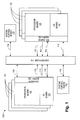
- the computer system 100 comprises a pair of system control boards 102, 105 coupled through a center plane 110 (e . g ., a back plane or a switch) via a plurality of respective communication links 116 to a plurality of system board sets 120.
- the communication links 116 take the form of edge connectors for making electrical or optical connections. It will be appreciated, however, that the communication links 116 may alternatively take the form of cables or various other types of interfaces without departing from the scope of the present invention.
- one of the system control boards 102 serves as the "primary" system control board for providing system controller resources for the computer system 100 and managing the overall operation thereof.
- Another "secondary" system control board 105 which may be functionally and/or structurally identical to the primary system control board 102, serves as a backup for managing the system 100 if the primary system control board 102 fails or is otherwise made unavailable.
- Each system controller board 102, 105 provides several services to the computer system 100. These services may include master clock generation and control, domain initialization, configuration, and reconfiguration, electrical power control, system component failover control, and user notification and interfacing.
- the plurality of communications links 116 provides monitor and control signals between the system control boards 102, 105 and the plurality of system board sets 120.
- the computer system 100 further includes the plurality of system board sets 120 coupled to the center plane 110 via a plurality of respective communication links 115.
- the communication links 115 include data links and address links.
- the communication links 115 take the form of edge connectors for making electrical or optical connections. It will be appreciated, however, that the communication links 115 may alternatively take the form of cables or various other types of interfaces without departing from the scope of the present invention.
- the system board sets 120 each comprise one or more boards, which may include a processor board 125, an I/O board 130, and an expander board 135.
- the processor board 125 may include a plurality of processors and/or memories for executing various computing tasks.
- the I/O board 130 may manage I/O cards, such as peripheral component interface (PCI) cards and optical cards that are installed in the system 100 for connection to various I/O devices (not shown).
- PCI peripheral component interface
- the expander board 135 allows both the processor board 125 and I/O board 130 to interface with the center plane 110.
- the computer system 100 may include up to eighteen expander boards 135, with each expander board 135 having a slot for accommodating a single processor board 125 and a single I/O board 130, for thirty-six boards 125, 130.
- the expander board 135 may alternatively be configured to accommodate various arrangements of processor boards 125 and I/O boards 130.
- the expander board 135 may be alternatively configured to accommodate two processor boards 125 or two I/O boards 130, instead of one processor board 125 and one I/O board 130 as shown in Fig. 1, without departing from the scope of the present invention.
- the computer system 100 may be configured with a greater or fewer numbers of boards 125, 130, 135 than provided in the examples above without departing from the scope of the present invention.
- the center plane 110 serves as a communication medium for the plurality of system board sets 120 and system control boards 102, 105 to communicate with one another.
- the center plane 110 takes the form of a plurality of 18 x 18 crossbars to accommodate communications between the thirty-six boards 125, 130. Accordingly, the center plane 110 may permit the two system control boards 102, 105 to communicate with each other or with other system board sets 120, as well as to allow the system board sets 120 to communicate with each other.
- the system resources (e . g ., processor boards 125, I/O boards 130) of the computer system 100 may be dynamically subdivided under the control of the system controller boards 102, 105 into a plurality of system domains, where each domain may have a separate boot disk to execute a specific instance of an operating system, separate and/or shared disk storage, network interfaces, and/or I/O interfaces.
- Each domain may in effect operate as a separate machine that performs a variety of user-configured services.
- one or more domains may be designated as an application server, a web server, a database server, etc.
- each domain may be allocated to a specific department within a company or organization.
- one domain may be allocated to a marketing department and another domain may be allocated to an accounting department to accommodate their respective computing needs.
- the computer system 100 may be shared by a few smaller companies or organizations through a computer service company, where it would otherwise be impractical for any one company or organization to purchase and maintain the computer system 100.
- each such company or organization could be allocated a specific grouping of system resources from the system 100 ( i . e ., allocated one or more domains) for their individual use.
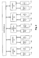
- Fig. 2 shows a block diagram of an example of a domain configuration that may be employed in the system of Fig. 1, according to one embodiment of the present invention.
- the system resources of the computer system 100 are divided into two domains under the control of the system controller boards 102, 105.
- the first domain is identified by the numeral "1”, and the system resources (e . g ., processor boards 125, I/O boards 130, etc.) that are allocated to the first domain are labeled accordingly.
- the second domain is identified by the numeral "2", and its corresponding grouping of system resources are labeled by the numeral "2".
- expander boards 205, 210 are associated by the primary system controller board 102 with processor boards 230, 240 and I/O boards 235, 245 that are allocated within domain 1.
- Expander boards 215, 220 are associated by the primary system controller board 102 with processor boards 260, 270 and I/O boards 265, 275 that are allocated within domain 2.
- each domain defines a particular grouping of system resources within the computer system 100 to perform a particular task or set of tasks, which the domain is formed to accomplish.
- the expander board 135 When the expander board 135 is interfaced with a processor board 125 and I/O board 130 within the same domain, it is referred to as a "non-split" expander or a "non-split” slot.
- the expander boards 205, 210 and the expander boards 215, 220 are non-split expanders because they are interfaced with system resources from a single domain.
- the expander boards 205, 210 respectively interface with the processor boards 230, 240 and the I/O boards 235, 245 from the same domain ( i . e ., domain 1).
- the expander boards 215, 220 respectively interface with the processor boards 260, 270 and the I/O boards 265, 275 from the same domain ( i . e ., domain 2).
- the expander board 225 (i . e ., expander C), on the other hand, interfaces with system resources from differing domains. That is, the expander board 225 is interfaced with the processor board 250 from domain 1 and the I/O board 255 from domain 2.
- the expander board 135 is interfaced with system resources from differing domains, it is referred to as a "split" expander or "split" slot. Accordingly, in the example provided in Fig. 2, the expander board 225 is a split expander.
- a domain may be formed of an entire system board set 120, one or more boards (e.g., processor board 125, I/O board 130) from selected system board sets 120, or a combination thereof. Additionally, it will be appreciated that physical proximity of the boards is not necessary to be within a particular domain. It will further be appreciated that the number of domains need not necessarily be limited to two as shown in the example of Figure 2, but may include several additional domains. For example, it is conceivable for each system board set 120 within the system 100 to form its own respective domain. Alternatively, all system board sets 120 may form a single domain. It will also be appreciated that several other arrangements of the system resources may be formed, and, thus, need not be limited to the particular arrangement of system resources illustrated in Fig. 2.
- the system 100 is configured to perform intra -domain communication, i . e ., communication solely within domain 1 and communication solely within domain 2, but not between domains 1 and 2.
- intra-domain communication within the computer system 100
- the transactions that occur in one domain on a non-split expander board do not affect the transactions that occur in the other domain because the expander board 135 interfaces solely with processor and/or I/O boards 125, 130 within one domain ( i . e ., either domain 1 or domain 2).
- the transactions for the processor board 250 (shown in Fig. 2) of domain 1 and the I/O board 255 of domain 2 that are coupled to the split expander 225 are independent of one another, i.e., communication occurs solely between the system resources within domain 1 and solely between the system resources of domain 2.
- the split expander board 225 With the split expander board 225, however, intra-domain communication of one domain may be adversely affected if the other domain is "down" ( i . e ., has failed). That is, because the split expander board 225 handles transactions for both domains, if one domain goes down (such as domain 1, for example), it may adversely affect the operation of the other domain ( i . e ., domain 2) sharing the split expander board 225. Accordingly, if the system resources for one domain go down, the system resources for the other domain may go down as well because of the two independent domains sharing the same expander board 135. The primary system controller board 102 handles the reconfiguration within the failed domain without affecting other domains to the extent possible (e.g., when no split expander board 225 is involved).
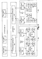
- FIG. 3 depicts a block diagram of an example of a system board set (expander board D 215, processor board 260, I/O board 265) coupled to the center plane 110, according to one embodiment of the present invention.
- the center plane 110 includes an address crossbar 305, a response crossbar 310, and a data crossbar 315.
- the expander board D 215 includes a system address controller 320 and a system data controller 325.
- the system address controller 320 is coupled to the address crossbar 305 and the response crossbar 310.
- the system data controller 325 is coupled to the data crossbar 315.
- the illustrated embodiment of the processor board 260 includes an address repeater 330, a data switch 335, a plurality of processors (CPUs) 355, a plurality of memories 360, and a plurality of data switches 350.
- the address repeater 330 is coupled to receive address information from the system address controller 320.
- the address repeater 330 is also coupled to transmit address information to one or more CPUs 355.
- the data switch 335 is coupled to receive data from the system data controller 325.
- Each CPU 355 is coupled to receive address information from the address repeater 330 and to provide address information to a respective memory 360.
- Each data switch 350 is coupled to receive data through the data switch 335.
- Each data switch 350 is also coupled to provide data to a plurality of the CPUs 355 and a plurality of the memories 360.
- the illustrated embodiment of the I/O board 265 includes an address repeater 340, a data switch 345, a plurality of I/O controllers ( e . g ., PCI controllers) 365, and a plurality of I/O cards ( e . g ., PCI cards) 370.
- the address repeater 340 is coupled to receive address information from the system address controller 320.
- the address repeater 340 is also coupled to transmit address information to each PCI controller 365.
- the data switch 345 is coupled to receive data from the system data controller 325.
- Each PCI controller 365 is coupled to receive address information from the address repeater 340 and to provide address information to a respective plurality of PCI cards 370.
- Each PCI controller 365 is also coupled to receive data through the data switch 345 and to provide data to the respective plurality of PCI cards 370.
- Each of the respective plurality of PCI cards 370 is additionally configured to share data directly.
- each of the plurality of PCI cards 370 is placed in a hot swappable PCI cassette (not shown) for ease of removal and replacement.
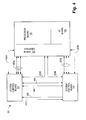
- FIG. 4 shows a functional block diagram 400 of redundant interconnections among a system board set 120 and two system controller boards 102 and 105 according to one embodiment of the present invention.
- the block diagram 400 includes the primary system controller board 102, the secondary system controller board 105, and the system board set 120, which includes the processor board 125, the I/O board 130, and the expander board 135.
- the primary system controller board 102 is connected to the secondary system controller board 105 through an IIC (Inter-Integrated Circuit) link 460 sourced on the primary system controller board 102, an IIC link 465 sourced on the secondary system controller board 105, and Ethernet links 440 and 445.
- the primary system controller board 102 is connected to one or more expander boards 135 in the computer system 100 through a console bus 428A as well as a plurality of IIC links 455A.
- the primary system controller board 102 is also connected to one or more I/O boards 130 in the computer system 100 through Ethernet link 435A.
- the secondary system controller board 105 is connected to one or more expander boards 135 in the computer system 100 through a console bus 428B as well as a plurality of IIC links 455B.
- the secondary system controller board 105 is also connected to one or more I/O boards 130 in the computer system 100 through Ethernet link 435B.
- system controller board 102 an embodiment of the system controller board 102, according to one embodiment of the present invention, is shown.
- the system controller board 105 is identical to the system controller board 102 (although this is not required for all embodiments of the present invention).
- the system controller board 102 includes a master clock generator 505, a processor (CPU) 510, a memory 515, a bootable device 520, a first communications controller (e.g., Ethernet, token ring, etc.) 530, a console bus controller 525, and a second communications controller ( e . g ., IIC, System Management Bus, etc.) 550.
- a plurality of communications links (e.g., configured as 100BaseTX Ethernet) 435, 440, 445 is connected to the Ethernet controller 530.
- the plurality of Ethernet links 435 is configurable to couple to the plurality of I/O boards 130 in the computer system 100.
- the Ethernet links 440 and 445 are configurable to connect to another system controller board ( e .
- the console bus 428 is an 8-bit wide monitoring and control bus with a separate link coupled to each expander board 135. Other embodiments may use a different bus width for the console bus 428.
- a plurality of communications links e . g ., two-wire serial lines
- 460, 465 is connected to the IIC controller 550.
- the plurality of IIC links 455 is configurable to couple to or through the plurality of expander boards 135.
- the IIC links 460 and 465 are configurable to connect to and from another system controller board (e.g., 105), respectively.
- the master clock generator 505 outputs a master clock signal to be routed over clock line 501 to each of the various components of the computer system 100 that requires the master clock signal. Any suitable implementation of clock production and distribution known in the art may be employed.
- the processor 510 executes an operating system and program code that, along with the hardware (and any appropriate firmware) of the computer system 100, control the computer system 100.
- the processor 510 and the memory 515 may be implemented as desired using, for example, a SPARC® chip 510 and any variety of DRAM (dynamic random access memory) 515, as are well known in the art.
- SPARC® refers to products based on an architecture developed by SUN MICROSYSTEMS, INC.).
- the operating system is loaded from the bootable device 520.
- the bootable device 425 may be a SCSI (Small Computer Systems Interface, ANSI X3.131 - 1986) storage device such as a hard disk drive, or other device configured to initialize the operating system, as is well known in the art.
- a controller and/or interface for the bootable device 425 are well known in the art and for brevity will not be described herein.
- the Ethernet controller 530 may be implemented using a RIOTM ASIC (Application Specific Integrated Circuit).
- the RIOTM ASIC 545 available from SUN MICROSYSTEMS, INC., is a high performance I/O controller chip including an IEEE 802.3 MAC (Media Access Controller).
- the console bus controller 525 and the IIC controller 550 may be implemented using ASICs configured for those purposes.
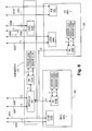
- FIG. 6 this depicts a block diagram showing control and monitoring signal paths in the example of a system board set of Fig. 3, according to one embodiment of the present invention.
- An IIC link 455A from the primary system controller board 102 and an IIC link 455B from the secondary system controller board 105 connect to logic 640A on the expander board 215.
- a console bus 428A from the primary system controller board 102 and a console bus 428B from the secondary system controller board 105 connect to a repeater 605 on the expander board 215.
- a console bus link extends from the repeater 605 to a monitoring chip (MC) 610A on the expander board 215.
- One or more IIC links extend from the monitoring chip 610A to one or more sensors 615.
- Two sensors 615A and 615B are shown on the expander board 215, however, those skilled in the art will appreciate that more or fewer sensors may be used, as dictated by the number and type of parameters being sensed.
- Another console bus link extends from the repeater 605 to a monitoring chip (MC) 610B on the processor board 260.
- One or more IIC links extend from the monitoring chip 610B to one or more sensors 615. Two sensors 615C and 615D are shown on the processor board 260.
- An IIC link 455A from the primary system controller board 102 and an IIC link 455B from the secondary system controller board 105 couple through the expander board 215 to logic 640B on the processor board 260.
- Another console bus link extends from the repeater 605 to a monitoring chip (MC) 610C on the I/O board 265.
- One or more IIC links extend from the monitoring chip 610C to one or more sensors 615.
- Two sensors 615E and 615F are shown on the I/O board 265.
- An IIC link 455A from the primary system controller board 102 and an IIC link 455B from the secondary system controller board 105 couple through the expander board 215 to logic 640C on the I/O board 265.
- the Ethernet link 435A from the primary system controller board 102 and the Ethernet link 435B from the secondary system controller board 105 couple through the expander board 215 to a hub 620 on the I/O board 265.
- the logic 640A, 640B, and 640C may be implemented as power monitoring and control circuits. Other circuits, such as for temperature monitoring and control, etc., may also be used.
- the monitoring chips 610A, 610B, and 610C may be differentiated based on where ( i . e ., board 215, 260, or 265) the MC 610 is placed. On the expander board 215, the monitoring chip 610A may monitor and/or control temperature, data throughput, data routing, and the like. On the processor board 260, the monitoring chip 610B may monitor and/or control booting configurations, routing configurations, reconfiguration, and the like.
- the monitoring chip 610C may monitor and/or control booting configurations, routing configurations, reconfiguration, data throughput, and the like.
- the sensors 615A-615F are appropriate to the respective function or device to be monitored.
- additional control lines may be routed on the expander board 215, the processor board 260, and/or the I/O board 265 from the respective monitoring chip 610 as needed.
- the logic 640A, 640B, and 640C may be discrete logic or an integrated circuit and may also be referred to herein as monitoring chips, control chips, and/or sensors, or the like.
- the plurality of IIC links from the MC 610A, the MC 610B, and MC 610C may transfer JTAG signals transmitted over the console bus links 428A and 428B.
- JTAG signals are well known in the art, referring to IEEE Standard 1149.1-1990 Test Access Port and Boundary-Scan Architecture and successors for the testing of internal interconnections.
- a memory (not shown), such as a SEEPROM (Serial Electrically Erasable Programmable ROM) configured with manufacturing information, serial numbers, and/or configuration data, may be coupled to one of the IIC links.
- SEEPROM Serial Electrically Erasable Programmable ROM
- the plurality of communication links 455, 560, 465 may be implemented using any desired protocol and is not restricted to the two-wire serial connections and protocols ( i . e ., IIC, etc.) described herein.
- the method 700 includes booting two system controllers 102, 105 in the computer system 100, in block 705. There may be more system controllers 102, 105 also booted in block 705. The method 700 also includes booting one or more domains in the computer system 100, in block 710.
- the one or more domains may be booted by, or under the control of, the primary system controller 102.
- the method 700 includes monitoring the computer system 100, in block 715. Monitoring the computer system 100 may include receiving monitoring data at the primary system controller 102, in block 760. Monitoring the computer system 100 may also include receiving monitoring data at the secondary system controller 105, in block 765. Monitoring the computer system 100 may also include updating the secondary system controller 105 from the primary system controller 102, in block 770.
- the method 700 also includes providing a heartbeat signal from the primary controller 102 to the secondary system controller 105, in block 720.
- the heartbeat signal may be provided at a predetermined interval.
- the heartbeat signal may be provided over one of the plurality of Ethernet links 440, 445 between the primary controller 102 and the secondary system controller 105.
- the method 700 may also include reconfiguring the computer system 100, in block 730.
- the reconfiguration may be performed by, or under the control of, the primary system controller 102.
- the reconfiguration may include creating, removing, and/or reconfiguring domains in the computer system 100.
- the reconfiguration may also include modifying connections, monitoring, and/or control functions in the computer system 100.
- the method also includes updating the secondary system controller 105 from the primary system controller 102, in block 735. Updating the secondary system controller 105 may include updating a system configuration stored at the secondary system controller 105.
- the method 800 includes determining if the heartbeat signal has been received at the secondary system controller 105, in decision block 805. If the heartbeat signal has been received, then the method 800 continues with decision block 810. If the heartbeat signal has not been received, then the method 800 continues with block 815.
- the method 800 determines if the updates correspond to the sensor data.
- the updates include changes to the system configuration stored at the secondary system controller 105.
- the sensor data includes data received from the sensors 615. If the updates correspond to the sensor data, then the method 800 may return to decision block 805. If the updates do not correspond to the sensor data, then the method moves to block 815.
- the method 800 includes the secondary system controller 105 taking over the operations of the primary system controller 102.
- the secondary system controller 105 has determined that the primary system controller 102 has failed.
- the method 800 optionally includes replacing the failed primary system controller 102, from block 815, with a new secondary system controller 105 (block 820).
- the original secondary system controller 105 is now the new primary system controller 102.
- monitoring and control of the computer system 100 are substantially continuous due to the failover of the system controller functions from the primary system controller 102 to the secondary system controller 105.
- the failed primary system controller 102 may then be replaced with the new secondary system controller 105.
- redundant monitoring and control links 440, 445, 460, 465, etc. may allow for the failover between the primary system controller 102 and the secondary system controller 105 to be seamless to the operations of the computer system 100.
- the secondary system controller 105 will then take over for the "failed" primary system controller 102.
- the "failed" primary system controller may then be removed as desired.
- the "failed" primary system controller 102 may then be reinitialized as the new secondary system controller 105. The user may thus reverse the roles of the primary system controller 102 and the secondary system controller 105, as desired.
- the software-implemented aspects described herein are typically encoded on some form of program storage medium or implemented over some type of transmission medium.
- the program storage medium may be magnetic (e.g., a floppy disk or a hard drive) or optical (e.g., a compact disk read only memory, or "CD ROM"), and may be read only or random access.
- the transmission medium may be twisted wire pairs, coaxial cable, optical fiber, or some other suitable transmission medium known to the art.
Landscapes
- Engineering & Computer Science (AREA)
- Theoretical Computer Science (AREA)
- Physics & Mathematics (AREA)
- General Engineering & Computer Science (AREA)
- General Physics & Mathematics (AREA)
- Software Systems (AREA)
- Quality & Reliability (AREA)
- Computer Hardware Design (AREA)
- Computer Security & Cryptography (AREA)
- Hardware Redundancy (AREA)
- Multi Processors (AREA)
Abstract
Description
Claims (32)
- A system controller, comprising:a processor;a memory; anda plurality of input/output (I/O) controllers each configurable with a plurality of I/O connections to another system controller, wherein each of the plurality of I/O controllers is further configurable with an I/O connection to each of one or more monitored devices.
- The system controller of claim 1, wherein one of the plurality of I/O controllers includes an Ethernet controller.
- The system controller of claim 1 or 2, wherein one of the plurality of I/O controllers includes an IIC controller.
- The system controller of any preceding claim, wherein the processor executes software configured to monitor the one or more monitored components over the I/O connections to each of the one or more monitored devices.
- The system controller of claim 4, wherein the software is further configured to update a configuration of at least one of the one or more monitored components in response to data received from the one or more monitored devices.
- The system controller of claim 5, wherein the software is further configured to update the another system controller with the configuration of the at least one of the one or more monitored components.
- The system controller of any preceding claim, further comprising a bootable device.
- The system controller of claim 7, wherein the bootable device is configured to store an operating system executable by the processor, wherein the bootable device is further configured to store software including instructions that configure the processor to monitor the one or more monitored devices.
- A computer system, comprising:one or more sensors;a plurality of system controller as claimed in preceding claim,
wherein the plurality of system controllers includes a primary system controller and a secondary system controller;one or more processors;one or more memories; andone or more I/O devices;
wherein the primary system controller is configured to configure the one or more processors,
the one or more memories, and the one or more I/O devices into one or more domains, and wherein the primary system controller is further configured to update the secondary
system controller with a system configuration. - A computer system, comprising:one or more sensors;a plurality of system controller, each comprising;wherein the plurality of system controllers includes a primary system controller and a secondary system controller;a processor;a memory; anda plurality of input/output (I/O) controllers each configurable with a plurality of I/O connections to another of the plurality of system controllers, wherein each of the plurality of I/O controllers is further configurable with an I/O connection to each of one or more sensors;one or more processors;one or more memories; andone or more I/O devices;
wherein the primary system controller is configured to configure the one or more processors,
the one or more memories, and the one or more I/O devices into one or more domains, and wherein the primary system controller is further configured to update the secondary
system controller with a system configuration. - The computer system of claim 10, wherein the processor in each system controller executes software configured to monitor the one or more sensors over the I/O connections to each of the one or more sensors.
- The computer system of claim 11, further comprising:wherein the software is further configured to update a configuration of the device associated with the sensor in response to data received from the sensor.a device associated with a sensor of the one or more sensors;
- The computer system of claim 12, wherein the software is further configured to update the one or more secondary system controllers with the configuration of the device associated with the sensor.
- The computer system of claim 12 or 13, further comprising:wherein the software is further configured to update the memory associated with the devicea memory associated with the device associated with the sensor, wherein the memory is configured to store configuration data for the device;
associated with the sensor over the I/O connection. - A computer system, comprising:a plurality of sensors;a center plane;one or more processor boards coupled to the center plane;one or more input/output (I/O) boards coupled to the center plane; anda plurality of system controllers each coupled to the center plane, the one or more processor boards, and the one or more I/O boards, wherein each of the plurality of system controllers includes a plurality of input/output (I/O) controllers each configurable with a plurality of I/O connections to another of the plurality of system controllers, wherein each of the plurality of I/O controllers is further configurable with an I/O connection to each of the plurality of sensors.
- The computer system of claim 15, wherein each of the one or more processor boards includes at least one of the plurality of sensors.
- The computer system of claim 15 or 16, wherein each of the one or more I/O boards includes at least one of the plurality of sensors.
- The computer system of any of claims 15 to 17, wherein the center plane includes at least one of the plurality of sensors.
- A method of operating a computer system, the method comprising:booting a plurality of system controllers configured as a primary system controller and at least one secondary system controller;booting one or more domains in the computer system from the primary system controller;updating a system configuration on the primary system controller; andupdating the system configuration on the secondary system controller from the primary system controller.
- The method of claim 19, further comprising:monitoring the computer system from the primary system controller.
- The method of claim 20, wherein monitoring the computer system from the primary system controller further comprises monitoring at least one of the one or more domains from the primary system controller.
- The method of any of claims 19 to 21, further comprising:monitoring the computer system from the secondary system controller.
- The method of claim 22, wherein monitoring the computer system from the secondary system controller comprises monitoring at least one of the one or more domains from the secondary system controller.
- The method of any of claims 19 to 23, further comprising:providing a heartbeat signal from the primary system controller to the secondary system controller.
- The method of claim 24, wherein providing the heartbeat signal from the primary system controller to the secondary system controller comprises providing the heartbeat signal from the primary system controller to the secondary system controller at a predetermined interval.
- The method of claim 24 or 25, further comprising:receiving the heartbeat signal from the primary system controller at the secondary system controller.
- The method of any of claims 24 to 26, further comprising:failing to receive the heartbeat signal from the primary system controller at the secondary system controller;determining that the primary system controller is a failed primary system controller, in response to failing to receive the heartbeat signal from the primary system controller at the secondary system controller; andreplacing the failed primary system controller with the secondary system controller as the primary system controller, in response to determining that the primary system controller is the failed primary system controller.
- The method of claim 27, further comprising:removing the failed primary system controller; andreplacing the failed primary system controller with a secondary system controller.
- The method of claim 27 or 28, further comprising:monitoring the computer system from the primary system controller.
- A computer readable medium encoded with instructions that, when executed by a computer system, perform a method for operating the computer system as claimed in any of claims 19 to 29.
- A computer readable medium encoded with instructions that, when executed by a computer system, perform a method for operating the computer system, the method comprising:booting a plurality of system controllers configured as a primary system controller and at least one secondary system controller;booting one or more domains in the computer system from the primary system controller;updating a system configuration on the primary system controller; andupdating the system configuration on the secondary system controller from the primary system controller.
- A computer system, comprising:a plurality of system controllers configured as a primary system controller and at least one secondary system controller;means for booting plurality of system controllersmeans for booting one or more domains in the computer system;means for updating a system configuration on the primary system controller; andmeans for updating the system configuration on the secondary system controller.
Applications Claiming Priority (2)
| Application Number | Priority Date | Filing Date | Title |
|---|---|---|---|
| US998019 | 2001-11-30 | ||
| US09/998,019 US6901531B2 (en) | 2001-11-30 | 2001-11-30 | Automatic system control failover |
Publications (2)
| Publication Number | Publication Date |
|---|---|
| EP1316890A2 true EP1316890A2 (en) | 2003-06-04 |
| EP1316890A3 EP1316890A3 (en) | 2006-03-29 |
Family
ID=25544663
Family Applications (1)
| Application Number | Title | Priority Date | Filing Date |
|---|---|---|---|
| EP02258233A Withdrawn EP1316890A3 (en) | 2001-11-30 | 2002-11-29 | Computer system with multiple system controllers |
Country Status (2)
| Country | Link |
|---|---|
| US (1) | US6901531B2 (en) |
| EP (1) | EP1316890A3 (en) |
Cited By (1)
| Publication number | Priority date | Publication date | Assignee | Title |
|---|---|---|---|---|
| GB2398404A (en) * | 2003-02-13 | 2004-08-18 | Sun Microsystems Inc | Configuring the boot options of a multi-domain system |
Families Citing this family (11)
| Publication number | Priority date | Publication date | Assignee | Title |
|---|---|---|---|---|
| US7035952B2 (en) * | 2003-09-24 | 2006-04-25 | Hewlett-Packard Development Company, L.P. | System having storage subsystems and a link coupling the storage subsystems |
| US7039741B2 (en) * | 2003-09-25 | 2006-05-02 | International Business Machines Corporation | Method and apparatus for implementing resilient connectivity in a serial attached SCSI (SAS) domain |
| US7155552B1 (en) * | 2004-09-27 | 2006-12-26 | Emc Corporation | Apparatus and method for highly available module insertion |
| US7412291B2 (en) * | 2005-01-12 | 2008-08-12 | Honeywell International Inc. | Ground-based software tool for controlling redundancy management switching operations |
| US20070233926A1 (en) * | 2006-03-10 | 2007-10-04 | Inventec Corporation | Bus width automatic adjusting method and system |
| US9058306B2 (en) | 2006-08-31 | 2015-06-16 | Dell Products L.P. | Redundant storage enclosure processor (SEP) implementation for use in serial attached SCSI (SAS) environment |
| KR101079592B1 (en) * | 2006-11-03 | 2011-11-04 | 삼성전자주식회사 | Display apparatus and information update method thereof |
| US9710342B1 (en) * | 2013-12-23 | 2017-07-18 | Google Inc. | Fault-tolerant mastership arbitration in a multi-master system |
| CN109697179B (en) * | 2017-10-24 | 2022-06-24 | 英业达科技有限公司 | Hardware resource expansion system and hot plug management device |
| US11579592B2 (en) | 2019-08-12 | 2023-02-14 | Battelle Energy Alliance, Llc | Systems and methods for control system security |
| US20250330369A1 (en) * | 2024-04-22 | 2025-10-23 | Arista Networks, Inc. | Fast Detection of OAM Processor (OAMP) Failure Using Hardware Acceleration |
Family Cites Families (11)
| Publication number | Priority date | Publication date | Assignee | Title |
|---|---|---|---|---|
| US5070477A (en) * | 1987-04-13 | 1991-12-03 | Unisys Coporation | Port adapter system including a controller for switching channels upon encountering a wait period of data transfer |
| US4894828A (en) * | 1987-12-22 | 1990-01-16 | Amdahl Corporation | Multiple sup swap mechanism |
| US5163052A (en) * | 1989-10-12 | 1992-11-10 | Ncr Corporation | High reliability computer diagnostics system |
| US5832222A (en) * | 1996-06-19 | 1998-11-03 | Ncr Corporation | Apparatus for providing a single image of an I/O subsystem in a geographically dispersed computer system |
| US5957985A (en) * | 1996-12-16 | 1999-09-28 | Microsoft Corporation | Fault-resilient automobile control system |
| US6009535A (en) * | 1997-06-30 | 1999-12-28 | Emc Corporation | SCSI adaptor failover for a disk drive system |
| US6279046B1 (en) * | 1999-05-19 | 2001-08-21 | International Business Machines Corporation | Event-driven communications interface for logically-partitioned computer |
| US6742139B1 (en) * | 2000-10-19 | 2004-05-25 | International Business Machines Corporation | Service processor reset/reload |
| US20030061326A1 (en) | 2001-09-25 | 2003-03-27 | Gilbert Gary L. | Managing one or more domains in a system |
| US6915450B2 (en) | 2001-11-01 | 2005-07-05 | Sun Microsystems, Inc. | Method and apparatus for arbitrating transactions between domains in a computer system |
| US20030097556A1 (en) | 2001-11-16 | 2003-05-22 | Gilbert Gary L. | Method and apparatus for providing simplified booting of domains in a multi-domain computer system |
-
2001
- 2001-11-30 US US09/998,019 patent/US6901531B2/en not_active Expired - Lifetime
-
2002
- 2002-11-29 EP EP02258233A patent/EP1316890A3/en not_active Withdrawn
Cited By (3)
| Publication number | Priority date | Publication date | Assignee | Title |
|---|---|---|---|---|
| GB2398404A (en) * | 2003-02-13 | 2004-08-18 | Sun Microsystems Inc | Configuring the boot options of a multi-domain system |
| GB2398404B (en) * | 2003-02-13 | 2005-06-01 | Sun Microsystems Inc | Method and apparatus for configuring the boot options of a multi-domain system |
| US7181604B2 (en) | 2003-02-13 | 2007-02-20 | Sun Microsystems, Inc. | Method and apparatus for configuring the boot options of a multi-domain system |
Also Published As
| Publication number | Publication date |
|---|---|
| EP1316890A3 (en) | 2006-03-29 |
| US6901531B2 (en) | 2005-05-31 |
| US20030105987A1 (en) | 2003-06-05 |
Similar Documents
| Publication | Publication Date | Title |
|---|---|---|
| US6023736A (en) | System for dynamically configuring I/O device adapters where a function configuration register contains ready/not ready flags corresponding to each I/O device adapter | |
| TWI331281B (en) | Method and apparatus for shared i/o in a load/store fabric | |
| US6901531B2 (en) | Automatic system control failover | |
| TWI328168B (en) | Method of and circuitry for reconfiguring links of a pci express bus of an information handling system, and information handling system | |
| US7120711B2 (en) | System and method for communicating over intra-hierarchy and inter-hierarchy links | |
| US7631050B2 (en) | Method for confirming identity of a master node selected to control I/O fabric configuration in a multi-host environment | |
| US6917999B2 (en) | Platform and method for initializing components within hot-plugged nodes | |
| EP0898227A1 (en) | Semaphore in system I/O space | |
| TWI807800B (en) | Datacenter-ready secure control module and control method | |
| US12361133B2 (en) | System-level service discovery in a multi-baseboard management controller (BMC) environment | |
| US7734858B2 (en) | Fabric interposer for blade compute module systems | |
| US20030018923A1 (en) | Platform and method for supporting hibernate operations | |
| US12461878B2 (en) | System, method, apparatus and architecture for dynamically configuring device fabrics | |
| US11093426B1 (en) | USB recepticle configuration and system therefor | |
| US12332990B2 (en) | Extended reality assistance provided via security protocol data model (SPDM) | |
| US20060174085A1 (en) | Storage enclosure and method for the automated configuration of a storage enclosure | |
| US6704823B1 (en) | Method and apparatus for dynamic allocation of interrupt lines through interrupt sharing | |
| US11442763B2 (en) | Virtual machine deployment system using configurable communication couplings | |
| US20200341924A1 (en) | Processor/Endpoint Connection Configuration System | |
| US6769069B1 (en) | Service processor control of module I / O voltage level | |
| US11093422B2 (en) | Processor/endpoint communication coupling configuration system | |
| US20030097556A1 (en) | Method and apparatus for providing simplified booting of domains in a multi-domain computer system | |
| CN118410003B (en) | Computer motherboard and method for setting central processing unit | |
| US20070237071A1 (en) | Input-output fabric conflict detection and resolution in a blade compute module system | |
| US20250138968A1 (en) | Systems and methods to abstract hardware access in baseboard management controllers (bmcs) |
Legal Events
| Date | Code | Title | Description |
|---|---|---|---|
| PUAI | Public reference made under article 153(3) epc to a published international application that has entered the european phase |
Free format text: ORIGINAL CODE: 0009012 |
|
| AK | Designated contracting states |
Designated state(s): AT BE BG CH CY CZ DE DK EE ES FI FR GB GR IE IT LI LU MC NL PT SE SK TR |
|
| AX | Request for extension of the european patent |
Extension state: AL LT LV MK RO SI |
|
| PUAL | Search report despatched |
Free format text: ORIGINAL CODE: 0009013 |
|
| AK | Designated contracting states |
Kind code of ref document: A3 Designated state(s): AT BE BG CH CY CZ DE DK EE ES FI FR GB GR IE IT LI LU MC NL PT SE SK TR |
|
| AX | Request for extension of the european patent |
Extension state: AL LT LV MK RO SI |
|
| RIC1 | Information provided on ipc code assigned before grant |
Ipc: G06F 11/00 20060101ALI20060203BHEP Ipc: G06F 13/12 20060101ALI20060203BHEP Ipc: G06F 13/38 20060101AFI20030303BHEP |
|
| AKX | Designation fees paid | ||
| REG | Reference to a national code |
Ref country code: DE Ref legal event code: 8566 |
|
| STAA | Information on the status of an ep patent application or granted ep patent |
Free format text: STATUS: THE APPLICATION IS DEEMED TO BE WITHDRAWN |
|
| 18D | Application deemed to be withdrawn |
Effective date: 20060630 |