EP1316795A1 - Liquid-containing substance analyzing device and liquid-containing substance analyzing method - Google Patents
Liquid-containing substance analyzing device and liquid-containing substance analyzing method Download PDFInfo
- Publication number
- EP1316795A1 EP1316795A1 EP01956842A EP01956842A EP1316795A1 EP 1316795 A1 EP1316795 A1 EP 1316795A1 EP 01956842 A EP01956842 A EP 01956842A EP 01956842 A EP01956842 A EP 01956842A EP 1316795 A1 EP1316795 A1 EP 1316795A1
- Authority
- EP
- European Patent Office
- Prior art keywords
- liquid
- light
- substrate
- light source
- onto
- Prior art date
- Legal status (The legal status is an assumption and is not a legal conclusion. Google has not performed a legal analysis and makes no representation as to the accuracy of the status listed.)
- Granted
Links
Images




Classifications
-
- G—PHYSICS
- G01—MEASURING; TESTING
- G01N—INVESTIGATING OR ANALYSING MATERIALS BY DETERMINING THEIR CHEMICAL OR PHYSICAL PROPERTIES
- G01N21/00—Investigating or analysing materials by the use of optical means, i.e. using sub-millimetre waves, infrared, visible or ultraviolet light
- G01N21/62—Systems in which the material investigated is excited whereby it emits light or causes a change in wavelength of the incident light
- G01N21/63—Systems in which the material investigated is excited whereby it emits light or causes a change in wavelength of the incident light optically excited
- G01N21/64—Fluorescence; Phosphorescence
- G01N21/645—Specially adapted constructive features of fluorimeters
- G01N21/6452—Individual samples arranged in a regular 2D-array, e.g. multiwell plates
-
- B—PERFORMING OPERATIONS; TRANSPORTING
- B01—PHYSICAL OR CHEMICAL PROCESSES OR APPARATUS IN GENERAL
- B01L—CHEMICAL OR PHYSICAL LABORATORY APPARATUS FOR GENERAL USE
- B01L3/00—Containers or dishes for laboratory use, e.g. laboratory glassware; Droppers
- B01L3/50—Containers for the purpose of retaining a material to be analysed, e.g. test tubes
- B01L3/508—Rigid containers without fluid transport within
-
- B—PERFORMING OPERATIONS; TRANSPORTING
- B01—PHYSICAL OR CHEMICAL PROCESSES OR APPARATUS IN GENERAL
- B01L—CHEMICAL OR PHYSICAL LABORATORY APPARATUS FOR GENERAL USE
- B01L3/00—Containers or dishes for laboratory use, e.g. laboratory glassware; Droppers
- B01L3/50—Containers for the purpose of retaining a material to be analysed, e.g. test tubes
- B01L3/508—Rigid containers without fluid transport within
- B01L3/5085—Rigid containers without fluid transport within for multiple samples, e.g. microtitration plates
-
- B—PERFORMING OPERATIONS; TRANSPORTING
- B01—PHYSICAL OR CHEMICAL PROCESSES OR APPARATUS IN GENERAL
- B01L—CHEMICAL OR PHYSICAL LABORATORY APPARATUS FOR GENERAL USE
- B01L3/00—Containers or dishes for laboratory use, e.g. laboratory glassware; Droppers
- B01L3/50—Containers for the purpose of retaining a material to be analysed, e.g. test tubes
- B01L3/508—Rigid containers without fluid transport within
- B01L3/5088—Rigid containers without fluid transport within confining liquids at a location by surface tension, e.g. virtual wells on plates, wires
-
- B—PERFORMING OPERATIONS; TRANSPORTING
- B01—PHYSICAL OR CHEMICAL PROCESSES OR APPARATUS IN GENERAL
- B01L—CHEMICAL OR PHYSICAL LABORATORY APPARATUS FOR GENERAL USE
- B01L9/00—Supporting devices; Holding devices
- B01L9/56—Means for indicating position of a recipient or sample in an array
-
- G—PHYSICS
- G01—MEASURING; TESTING
- G01N—INVESTIGATING OR ANALYSING MATERIALS BY DETERMINING THEIR CHEMICAL OR PHYSICAL PROPERTIES
- G01N21/00—Investigating or analysing materials by the use of optical means, i.e. using sub-millimetre waves, infrared, visible or ultraviolet light
- G01N21/17—Systems in which incident light is modified in accordance with the properties of the material investigated
- G01N21/47—Scattering, i.e. diffuse reflection
-
- B—PERFORMING OPERATIONS; TRANSPORTING
- B01—PHYSICAL OR CHEMICAL PROCESSES OR APPARATUS IN GENERAL
- B01L—CHEMICAL OR PHYSICAL LABORATORY APPARATUS FOR GENERAL USE
- B01L2300/00—Additional constructional details
- B01L2300/08—Geometry, shape and general structure
- B01L2300/0809—Geometry, shape and general structure rectangular shaped
- B01L2300/0819—Microarrays; Biochips
-
- B—PERFORMING OPERATIONS; TRANSPORTING
- B01—PHYSICAL OR CHEMICAL PROCESSES OR APPARATUS IN GENERAL
- B01L—CHEMICAL OR PHYSICAL LABORATORY APPARATUS FOR GENERAL USE
- B01L2300/00—Additional constructional details
- B01L2300/16—Surface properties and coatings
- B01L2300/168—Specific optical properties, e.g. reflective coatings
-
- B—PERFORMING OPERATIONS; TRANSPORTING
- B01—PHYSICAL OR CHEMICAL PROCESSES OR APPARATUS IN GENERAL
- B01L—CHEMICAL OR PHYSICAL LABORATORY APPARATUS FOR GENERAL USE
- B01L3/00—Containers or dishes for laboratory use, e.g. laboratory glassware; Droppers
- B01L3/02—Burettes; Pipettes
- B01L3/0241—Drop counters; Drop formers
-
- Y—GENERAL TAGGING OF NEW TECHNOLOGICAL DEVELOPMENTS; GENERAL TAGGING OF CROSS-SECTIONAL TECHNOLOGIES SPANNING OVER SEVERAL SECTIONS OF THE IPC; TECHNICAL SUBJECTS COVERED BY FORMER USPC CROSS-REFERENCE ART COLLECTIONS [XRACs] AND DIGESTS
- Y10—TECHNICAL SUBJECTS COVERED BY FORMER USPC
- Y10T—TECHNICAL SUBJECTS COVERED BY FORMER US CLASSIFICATION
- Y10T436/00—Chemistry: analytical and immunological testing
- Y10T436/25—Chemistry: analytical and immunological testing including sample preparation
-
- Y—GENERAL TAGGING OF NEW TECHNOLOGICAL DEVELOPMENTS; GENERAL TAGGING OF CROSS-SECTIONAL TECHNOLOGIES SPANNING OVER SEVERAL SECTIONS OF THE IPC; TECHNICAL SUBJECTS COVERED BY FORMER USPC CROSS-REFERENCE ART COLLECTIONS [XRACs] AND DIGESTS
- Y10—TECHNICAL SUBJECTS COVERED BY FORMER USPC
- Y10T—TECHNICAL SUBJECTS COVERED BY FORMER US CLASSIFICATION
- Y10T436/00—Chemistry: analytical and immunological testing
- Y10T436/25—Chemistry: analytical and immunological testing including sample preparation
- Y10T436/2575—Volumetric liquid transfer
Definitions
- This invention concerns a liquid-contained substance analysis device and a liquid-contained substance analysis method for analyzing substances contained in a liquid, and particularly concerns those used for analysis of microvolumes of liquid.
- An object of this invention is thus to resolve the above problems and to provide a liquid-contained substance analysis device and a liquid-contained substance analysis method, which enable the positions of microvolumes of liquid to be ascertained smoothly and thereby enable substances contained in the liquid to be analyzed readily.
- a liquid-contained substance analysis device comprises: a mirror-finished substrate, onto which a liquid that is to be analyzed is dropped; a first light source for illuminating the substrate; a light detector, detecting scattered light resulting from the scattering of light from the first light source by the liquid or trace of the liquid that has been dropped onto the substrate; a position detector, detecting the position onto which the liquid has been dropped based on the scattered light detected by the light detector; a second light source, illuminating the position detected by the position detector with light of a shorter wavelength than the light output from the first light source; a fluorescence detector, detecting fluorescence resulting from the excitation of the liquid or trace of the liquid by the light that has been illuminated from the second light source; and an analyzer, analyzing substances contained in the liquid by the fluorescence detected by the fluorescence detector.
- the position at which the liquid exists can be detected readily. That is, since the mirror-finished substrate will not give rise to scattered light, it can be judged that the liquid or trace of the liquid exists when scattered light occurs.
- the substances contained in a microvolume of liquid can be analyzed smoothly.
- the second light source may be positioned so that the output light from the second light source intersects the normal to the substrate plane and the fluorescence detector may be positioned in the direction of the normal to the substrate plane.
- the reflected light output from the second light source will be prevented from becoming incident directly onto the fluorescence detector, thereby enabling a weak fluorescence to be detected.
- the surface of the substrate may be coated with a water-soluble organic thin film.
- the substrate surface becomes modified at a part at which a liquid has been dropped, thereby enabling the trace of the liquid to be detected even when the liquid evaporates.
- the substrate may be a silicon substrate on which a natural oxidation film has been formed.
- the substrate surface of a portion on which a liquid has been dropped becomes modified by the formation of a new silicon oxide film, thereby enabling the trace of the liquid to be detected even when the liquid evaporates.
- the above-described liquid-contained substance analysis device may furthermore be equipped with a stage for setting the substrate thereon and moving the substrate so that light from the first light source will be illuminated onto the substrate.
- the illumination positions of the light output from the first light source and second light source that illuminate the substrate can be shifted.
- a liquid-contained substance analysis method comprises: a liquid dropping step of dropping a liquid to be analyzed onto a mirror-finished substrate; a light illumination step of illuminating light onto the substrate by means of a first light source; a scattered light detection step of detecting scattered light resulting from the scattering of light from the first light source by the liquid or trace of the liquid that has been dropped onto the substrate in the liquid dropping step; a position detection step of detecting the position onto which the liquid has been dropped based on the scattered light detected in the scattered light detection step; a second light illumination step of illuminating the position detected in the position detection step with light from a second light source that outputs light of a shorter wavelength than the light output from the first light source; a fluorescence detection step of detecting the fluorescence resulting from the excitation of the liquid or trace of the liquid by the light illuminated in the second light illumination step; and an analysis step of analyzing substances contained in the liquid based on the fluorescence detected in the fluorescence detection step.
- the position at which the liquid exists can be detected readily. That is, since the mirror-finished substrate will not give rise to scattered light, it can be judged that the liquid or trace of the liquid exists when scattered light occurs.
- the substances contained in the microvolume of liquid can be analyzed smoothly.
- Fig. 1 is a diagram, showing the arrangement of a liquid-contained substance analysis device (referred to hereinafter as "analysis device") 10.
- Analysis device 10 comprises a motor-driven movable stage 12, a substrate 14, set on motor-driven movable stage 12, a liquid dropper 16 for dropping a liquid L to be analyzed onto substrate 14, and a first light source 18 and a second light source 20, each of which illuminates light onto substrate 14 and the liquid L that has been dropped onto substrate 14.
- Substrate 14 which is set on motor-driven movable stage 12, is mirror finished. Light that is perpendicularly incident on substrate 14 is thus reflected in the direction perpendicular to substrate 14.
- the surface of substrate 14 is also coated with a water-soluble thin film 14x.
- Thin film 14x is formed of a water-soluble organic thin film, in particular, water-soluble PVA (polyvinyl alcohol).
- PVA polyvinyl alcohol
- First light source 18 is positioned to output light substantially parallel to the substrate plane.
- a first half-mirror 22, is positioned along the output optical axis of first light source 18 and is tilted by 45° with respect to the optical axis .
- the output light from first light source 18 is thereby bent at a right angle in the direction of substrate 14.
- the output light bent by first half-mirror 22 is illuminated onto substrate 14.
- An objective lens 26 is disposed between first half-mirror 22 and substrate 14, and the output light from first light source 18 is illuminated onto a predetermined region (hereinafter, this predetermined region shall be referred to as "measurement spot") R on substrate 14 by means of objective lens 26.
- Objective lens 26 is preferably a dark-field lens. This is because with a dark-field objective lens 26, the illuminated light will be illuminated onto substrate 14 at an angle with respect to the substrate normal and the reflected light (from the substrate) that is directed in the substrate normal direction will thereby be reduced to enable a scattered light image of high contrast to be obtained.
- a focal depth adjustment optical device 28 is disposed along the output optical axis at a position near first light source 18 to provide an arrangement that enables the first and second light of different wavelengths to be adjusted to be equal in focal depth.
- Second light source 20 is a light source that outputs light of a shorter wavelength than first light source 18 and is an excitation light source for generation of fluorescence from liquid L. Second light source 20 outputs light substantially perpendicular to substrate 14 and is disposed so that its optical axis intersects the optical axis of the output light from first light source 18. At the position at which the output light from second light source 20 and the output light from first light source 18 intersect, a second half-mirror 24 is disposed in a manner that is tilted by 45° with respect to the output optical axis of second light source 20, and the output light from second light source 20 is thereby bent and made to progress along the same optical axis as the output light from first light source 18 and reach measurement spot R on substrate 14.
- Motor-driven movable stage 12 can move substrate 14 so that substantially the entire region of substrate 14 can be scanned by means of measurement spot R. Also, liquid dropper 16, for dropping liquid L, which is the subject of measurement, is disposed above motor-driven movable stage 12, and motor-driven movable stage 12 can move substrate 14 to a position at which liquid L is to be dropped by liquid dropper 16.
- Analysis device 10 comprises a light detector 30, which detects scattered light resulting from the scattering, by the liquid L or trace of the liquid L that exists on substrate 14, of light output from first light source 18 and illuminated onto substrate 14, and a fluorescence detector 32, which detects the fluorescence emitted from the liquid L as a result of the light output from second light source 20 and illuminated onto the liquid L that has been dropped onto substrate 14.
- Light detector 30 detects the scattered light scattered by the liquid L or a trace of the liquid L that exists on substrate 14 .
- Light detector 30 is disposed above substrate 14 so as to lie along the same straight line as substrate 14 and objective lens 26.
- An optical filter 36 for cutting light from the exterior, is disposed in front of the light detection surface of light detector 30.
- a half-mirror 34 is disposed in amanner that is tilted by 45° with respect to the normal to the substrate plane and splits the light from substrate 14 into a direction perpendicular to the optical axis.
- Fluorescence detector 32 is disposed along the optical axis of the split light. Fluorescence detector 32 detects the fluorescence emitted by excitation of substances contained in liquid L as a result of light output from second light source 20. Also, an optical filter 38, for cutting the reflected light of the excitation light output from second light source 20, is disposed in front of the light detection surface of fluorescence detector 32.
- Analysis device 10 furthermore has a computer 40.
- Computer 40 is connected to first light source 18, second light source 20, motor-driven movable stage 12, and liquid dropper 16 and controls the respective operations of these components.
- Computer 40 is also connected to light detector 30 and fluorescence detector 32, has the function of performing image processing and data analysis based on the light detected by the respective detectors 30 and 32, and thus functions as a position detector and as an analyzer.
- analysis device 10 shall now be described, and in accompaniment, a liquid-contained substance analysis method of this embodiment shall be described.
- the range onto which liquid L to be analyzed is dropped that is the range in which there is a possibility that liquid L or a trace of liquid L exists on substrate 14 shall be referred to as the "measurement range.”
- substrate 14 which has been mirror finished, is coated with a thin film 14x (510) and set on the upper surface of motor-driven movable stage 12. Substrate 14 is then moved by motor-driven movable stage 12 so that the measurement range will be set at the position onto which liquid L will be dropped by liquid dropper 16. Subsequently, a microvolume of liquid L is dropped onto substrate 14 by means of liquid dropper 16 (S12).
- Substrate 14 is then moved by motor-driven movable stage 12 so that measurement spot R will be contained within the measurement range (S14).
- Motor-driven measurement stage 12 is stopped once, light from first light source 18 is output, and light is illuminated onto measurement spot R of substrate 14 (S16) .
- the scattered light that is scattered by the liquid L or the trace of the liquid L that exists on substrate 14 is then detected by light detector 30 (S18).
- the scattered light is analyzed by computer 40 to detect the position of liquid L (S22). That is, if liquid L exists, since the illuminated light will be scattered by liquid L itself, the position of liquid L can thereby be detected. Also, even if liquid L has evaporated, since the surface of substrate 14 that has been modified by the dropped liquid L bulges so as to surround the location at which liquid L had existed, the position onto which liquid L had been dropped can be detected by analysis of the scattered light.
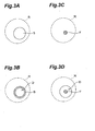
- Figs. 3A and 3B illustrate specific examples.
- Fig. 3A is a diagram, showing an image of scattered light S detected by light detector 30.
- an outline (liquid L trace) B on the surface of substrate 14 that has been modified by the dropped liquid L can be determined as shown in Fig. 3B.
- the position D onto which liquid L has been dropped is at the inner side of outline B.
- step (S14) of moving substrate 14 by means of motor-driven movable stage 12 is returned to.
- substrate 14 is moved so that the measurement spot R after movement of substrate 14 will be adjacent to the measurement spot R onto which light was illuminated previously.
- analysis device 10 judges whether or not measurements have been made for the entire measurement range (S30), and if measurements have been made for the entire measurement range, the measurements are ended. If measurements have not been made for the entire measurement range, the step of moving substrate 14 by means of motor-driven movable stage 12 is returned to again (S14).
- analysis device 10 of this embodiment has a first light source 18, which illuminates light onto a mirror-finished substrate 14, and a light detector 30, which detects the scattered light scattered by liquid L or a trace of liquid L that exists on substrate 14, if liquid L exists on substrate 14 even by a minute amount, the position of liquid L or trace of liquid L can be specified based on the detected scattered light. Analysis of an extremely minute amount of liquid L can thus be carried out smoothly.
- first light source 18 which illuminates light for detection of the position of liquid L, uses light that is longer in wavelength than the light of second light source 20, the liquid L that is subject to analysis will not be destroyed.
- liquid L which is to be analyzed
- the position of liquid L on substrate 14 is detected by illumination of light onto substrate 14 and analyzing the scattered light due to liquid L or trace of liquid L that exists on substrate 14, the position of liquid L can be detected even if it is extremely minute in amount. Analysis of an extremely minute amount of liquid L can thus be carried out smoothly.
- FIG. 4 is a diagram, showing analysis device 50 of the second embodiment.
- analysis device 50 of the second embodiment is the same in basic arrangement as analysis device 10 of the first embodiment, it differs in that second light source 20 is disposed so that light is illuminated from a direction that intersects the normal to the substrate plane.
- a lens 52 is disposed along the optical axis of the output light from second light source 20 to form an optical system for illuminating light onto a measurement spot R on a substrate 14.
- analysis device 50 of the second embodiment are the same as the operations of analysis device 10 of the first embodiment.
- analysis device 50 of the second embodiment provides the following effect.
- excitation light is made incident from a direction that intersects the normal to the substrate plane and the fluorescence that is emitted as a result of this excitation light is detected by a fluorescent detector disposed in the direction of the normal to the substrate plane. Since the reflected light of the excitation light will therefore not enter fluorescence detector 32 directly, the fluorescence emitted from liquid L can be detected even if it is weak.
- a substrate 14 which was coated on the surface with a thin film 14x formed of PVA, was used, a silicon substrate 14, having a silicon oxide film (natural oxidation film) as thin film 14x, may be used instead.
- a thin film 14x comprising silicon oxide, forms at the location onto which the liquid was dropped, thus enabling a so-called “watermark” to be left as a trace of liquid L on the silicon substrate and thus even if the liquid evaporates, the trace thereof can be detected.
- Fig. 5A is a diagram, showing the image of scattered light when a silicon substrate is used
- Fig. 5B is a diagram, showing the image of fluorescence in the same case.
- a range within a fixed radius centered about scattered light S must be set as the analysis range. The magnitude of this radius is determined by the diameter of the liquid drop formed by the extremely minute amount of the liquid, and, for example, when the liquid drop diameter is 70 ⁇ m, the analysis range is preferably set to be within a radius of 35 to 40 ⁇ m centered about scattered light S.
- substrate 14 is moved by means of motor-driven movable stage 12 to make measurement spot R be scanned over the entire measurement range of substrate 14, light may be illuminated over the entire measurement range or over a part of the measurement range (over a range wider than measurement spot R) of substrate 14 and a plurality of positions onto which liquid has been dropped may be detected in a batch by means of scattered light scattered by liquid L or traces of liquid L on substrate 14.
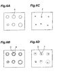
- FIGs. 6A, 6B, 6C, and 6D are diagrams, showing an example where the measurement range of substrate 14 is analyzed in a batch.
- This invention can be applied to a liquid-contained substance analysis device and a liquid-contained substance analysis method.
Landscapes
- Health & Medical Sciences (AREA)
- Chemical & Material Sciences (AREA)
- Analytical Chemistry (AREA)
- General Health & Medical Sciences (AREA)
- Clinical Laboratory Science (AREA)
- Chemical Kinetics & Catalysis (AREA)
- Hematology (AREA)
- Pathology (AREA)
- Biochemistry (AREA)
- Life Sciences & Earth Sciences (AREA)
- General Physics & Mathematics (AREA)
- Immunology (AREA)
- Physics & Mathematics (AREA)
- Nuclear Medicine, Radiotherapy & Molecular Imaging (AREA)
- Investigating, Analyzing Materials By Fluorescence Or Luminescence (AREA)
- Sampling And Sample Adjustment (AREA)
- Investigating Or Analysing Materials By Optical Means (AREA)
- Investigating Or Analysing Biological Materials (AREA)
Abstract
Description
Claims (6)
- A liquid-contained substance analysis device comprising:a mirror-finished substrate, onto which a liquid that is to be analyzed is dropped;a first light source for illuminating said substrate;a light detector, detecting scattered light resulting from the scattering of light from said first light source by said liquid or trace of said liquid that has been dropped onto said substrate;a position detector, detecting the position onto which said liquid has been dropped based on said scattered light detected by said light detector;a second light source, illuminating the position detected by said position detector with light of a shorter wavelength than the light output from said first light source;a fluorescence detector, detecting fluorescence resulting from the excitation of said liquid or trace of said liquid by the light that has been illuminated from said second light source; andan analyzer, analyzing substances contained in said liquid by the fluorescence detected by said fluorescence detector.
- The liquid-contained substance analysis device as set forth in Claim 1, wherein said second light source is positioned so that the output light from said second light source intersects the normal to the plane of said substrate plane and
said fluorescence detector is positioned in the direction of the normal to said substrate plane. - The liquid-contained substance analysis device as set forth in Claim 1, wherein the surface of said substrate is coated with a water-soluble organic thin film.
- The liquid-contained substance analysis device as set forth in Claim 1, wherein a silicon oxidation film is formed on the surface of the substrate.
- The liquid-contained substance analysis device as set forth in Claim 1, further comprising a stage for setting said substrate thereon and moving said substrate so that light from said first light source will be illuminated onto said substrate.
- A liquid-contained substance analysis method comprising:a liquid dropping step of dropping a liquid to be analyzed onto a mirror-finished substrate;a light illumination step of illuminating light onto said substrate by means of a first light source;a scattered light detection step of detecting scattered light resulting from the scattering of light from said first light source by said liquid or trace of said liquid that has been dropped onto the substrate in said liquid dropping step;a position detection step of detecting the position onto which said liquid has been dropped based on said scattered light detected in said scattered light detection step;a second light illumination step of illuminating the position detected in said position detection step with light from a second light source that outputs light of a shorter wavelength than the light output from said first light source;a fluorescence detection step of detecting the fluorescence resulting from the excitation of said liquid or trace of said liquid by the light illuminated in said second light illumination step; andan analysis step of analyzing substances contained in said liquid based on the fluorescence detected in said fluorescence detection step.
Applications Claiming Priority (3)
| Application Number | Priority Date | Filing Date | Title |
|---|---|---|---|
| JP2000244643 | 2000-08-11 | ||
| JP2000244643A JP4494606B2 (en) | 2000-08-11 | 2000-08-11 | Liquid-containing substance analysis apparatus and liquid-containing substance analysis method |
| PCT/JP2001/006938 WO2002014842A1 (en) | 2000-08-11 | 2001-08-10 | Liquid-containing substance analyzing device and liquid-containing substance analyzing method |
Publications (3)
| Publication Number | Publication Date |
|---|---|
| EP1316795A1 true EP1316795A1 (en) | 2003-06-04 |
| EP1316795A4 EP1316795A4 (en) | 2004-05-26 |
| EP1316795B1 EP1316795B1 (en) | 2005-11-16 |
Family
ID=18735303
Family Applications (1)
| Application Number | Title | Priority Date | Filing Date |
|---|---|---|---|
| EP01956842A Expired - Lifetime EP1316795B1 (en) | 2000-08-11 | 2001-08-10 | Liquid-containing substance analyzing device and liquid-containing substance analyzing method |
Country Status (6)
| Country | Link |
|---|---|
| US (1) | US6881587B2 (en) |
| EP (1) | EP1316795B1 (en) |
| JP (1) | JP4494606B2 (en) |
| AU (1) | AU2001278710A1 (en) |
| DE (1) | DE60115064T2 (en) |
| WO (1) | WO2002014842A1 (en) |
Families Citing this family (7)
| Publication number | Priority date | Publication date | Assignee | Title |
|---|---|---|---|---|
| JP4652049B2 (en) * | 2002-05-28 | 2011-03-16 | オウトジエノミクス・インコーポレーテツド | Level control pipette for automatic analyzer |
| JP4146310B2 (en) * | 2003-07-17 | 2008-09-10 | 浜松ホトニクス株式会社 | Method for evaluating composition uniformity and apparatus for evaluating composition uniformity |
| WO2011072396A1 (en) | 2009-12-18 | 2011-06-23 | Fpinnovations | An on-line macrocontaminant analyser and method |
| JP2013029326A (en) * | 2011-07-26 | 2013-02-07 | V Technology Co Ltd | Defect inspection method and defect inspection device for organic el panel |
| JP5112553B1 (en) * | 2011-09-09 | 2013-01-09 | シャープ株式会社 | Particle detector |
| WO2013162514A1 (en) * | 2012-04-24 | 2013-10-31 | Hewlett-Packard Development Company, L.P. | Apparatus for performing a sensing application |
| KR102549436B1 (en) * | 2021-04-01 | 2023-06-30 | 롭틱스(주) | Semiconductor circuit pattern inspection device using reflected light and fluorescence |
Family Cites Families (15)
| Publication number | Priority date | Publication date | Assignee | Title |
|---|---|---|---|---|
| US4934811A (en) * | 1988-04-01 | 1990-06-19 | Syntex (U.S.A.) Inc. | Apparatus and method for detection of fluorescence or light scatter |
| US5760900A (en) * | 1989-03-18 | 1998-06-02 | Canon Kabushiki Kaisha | Method and apparatus for optically measuring specimen |
| US5141871A (en) * | 1990-05-10 | 1992-08-25 | Pb Diagnostic Systems, Inc. | Fluid dispensing system with optical locator |
| US5270210A (en) * | 1992-07-16 | 1993-12-14 | Schiapparelli Biosystems, Inc. | Capacitive sensing system and wash/alignment station for a chemical analyzer |
| US5494829A (en) * | 1992-07-31 | 1996-02-27 | Biostar, Inc. | Devices and methods for detection of an analyte based upon light interference |
| JP2575270B2 (en) * | 1992-11-10 | 1997-01-22 | 浜松ホトニクス株式会社 | Method for determining base sequence of nucleic acid, method for detecting single molecule, apparatus therefor and method for preparing sample |
| JP3305181B2 (en) * | 1995-12-19 | 2002-07-22 | シスメックス株式会社 | Urine particle analyzer |
| EP0838850A3 (en) * | 1996-10-24 | 1999-05-06 | Hamamatsu Photonics K.K. | Method for placing flourescent single molecules on surface of substrate and method for visualizing structural defect of surface of substrate |
| JPH10185782A (en) * | 1996-10-24 | 1998-07-14 | Hamamatsu Photonics Kk | Method for arranging fluorescent single molecules on substrate surface and method for visualizing structural defects on substrate surface |
| US6071748A (en) * | 1997-07-16 | 2000-06-06 | Ljl Biosystems, Inc. | Light detection device |
| AU5223899A (en) * | 1998-07-27 | 2000-02-21 | Ljl Biosystems, Inc. | Apparatus and methods for spectroscopic measurements |
| JP2000111477A (en) * | 1998-09-30 | 2000-04-21 | Hamamatsu Photonics Kk | Fluorescence analysis substrate and fluorescence analyzer |
| JP3344328B2 (en) * | 1998-10-02 | 2002-11-11 | 松下電器産業株式会社 | Optical analyzer |
| US6228652B1 (en) * | 1999-02-16 | 2001-05-08 | Coulter International Corp. | Method and apparatus for analyzing cells in a whole blood sample |
| US6284465B1 (en) * | 1999-04-15 | 2001-09-04 | Agilent Technologies, Inc. | Apparatus, systems and method for locating nucleic acids bound to surfaces |
-
2000
- 2000-08-11 JP JP2000244643A patent/JP4494606B2/en not_active Expired - Fee Related
-
2001
- 2001-08-10 AU AU2001278710A patent/AU2001278710A1/en not_active Abandoned
- 2001-08-10 US US10/344,265 patent/US6881587B2/en not_active Expired - Fee Related
- 2001-08-10 DE DE60115064T patent/DE60115064T2/en not_active Expired - Fee Related
- 2001-08-10 EP EP01956842A patent/EP1316795B1/en not_active Expired - Lifetime
- 2001-08-10 WO PCT/JP2001/006938 patent/WO2002014842A1/en not_active Ceased
Also Published As
| Publication number | Publication date |
|---|---|
| WO2002014842A1 (en) | 2002-02-21 |
| DE60115064T2 (en) | 2006-08-10 |
| EP1316795A4 (en) | 2004-05-26 |
| DE60115064D1 (en) | 2005-12-22 |
| US20030170732A1 (en) | 2003-09-11 |
| AU2001278710A1 (en) | 2002-02-25 |
| EP1316795B1 (en) | 2005-11-16 |
| US6881587B2 (en) | 2005-04-19 |
| JP2002055051A (en) | 2002-02-20 |
| WO2002014842A9 (en) | 2003-01-23 |
| JP4494606B2 (en) | 2010-06-30 |
Similar Documents
| Publication | Publication Date | Title |
|---|---|---|
| US5648854A (en) | Alignment system with large area search for wafer edge and global marks | |
| US6441894B1 (en) | Optical autofocus for use with microtiter plates | |
| US6545755B1 (en) | Micro-Raman spectroscopy system for identifying foreign material on a semiconductor wafer | |
| KR100516405B1 (en) | Apparatus for inspecting an edge exposure area of wafer | |
| US7247825B2 (en) | Method and apparatus for scanning a specimen using an optical imaging system | |
| EP1932046B1 (en) | Fluorescence microscope | |
| US5446542A (en) | Mark position determining apparatus for use in exposure system | |
| EP1316795B1 (en) | Liquid-containing substance analyzing device and liquid-containing substance analyzing method | |
| EP3299861B1 (en) | Confocal raman microscope | |
| JP4320132B2 (en) | Defect observation method and defect observation apparatus | |
| US20080144006A1 (en) | Method for Measuring Topographic Structures on Devices | |
| KR20070056947A (en) | Optical system to detect the characteristics of the sample | |
| KR20010088425A (en) | X-ray spectroscopic analyzer having sample surface observation mechanism | |
| US6226087B1 (en) | Method for measuring the positions of structures on a mask surface | |
| JP2006352122A (en) | Method and system for determining drift of the position of a light beam relative to a chuck | |
| US20250012732A1 (en) | Surface inspection apparatus | |
| WO2003060589A1 (en) | Auto focussing device and method | |
| US5987160A (en) | Method and apparatus for inspecting a photoresist material by inducing and detecting fluorescence of the photoresist material | |
| KR102634513B1 (en) | Foreign substance detection apparatus, exposure apparatus and manufacturing method of article | |
| JP2000146532A (en) | Non-contact dimension measurement method by laser autofocus | |
| JP4892294B2 (en) | Microhole depth measurement method | |
| US20050112853A1 (en) | System and method for non-destructive implantation characterization of quiescent material | |
| JP7841022B2 (en) | Optical apparatus and measurement method | |
| JP2005030984A (en) | Optical measuring device | |
| JP2025152567A (en) | Laser processing method and laser processing device |
Legal Events
| Date | Code | Title | Description |
|---|---|---|---|
| PUAI | Public reference made under article 153(3) epc to a published international application that has entered the european phase |
Free format text: ORIGINAL CODE: 0009012 |
|
| 17P | Request for examination filed |
Effective date: 20030307 |
|
| AK | Designated contracting states |
Designated state(s): AT BE CH CY DE DK ES FI FR GB GR IE IT LI LU MC NL PT SE TR |
|
| AX | Request for extension of the european patent |
Extension state: AL LT LV MK RO SI |
|
| RBV | Designated contracting states (corrected) |
Designated state(s): DE FR GB |
|
| A4 | Supplementary search report drawn up and despatched |
Effective date: 20040416 |
|
| RIC1 | Information provided on ipc code assigned before grant |
Ipc: 7B 01L 3/00 B Ipc: 7G 01N 33/53 B Ipc: 7G 01N 21/64 A |
|
| GRAP | Despatch of communication of intention to grant a patent |
Free format text: ORIGINAL CODE: EPIDOSNIGR1 |
|
| GRAS | Grant fee paid |
Free format text: ORIGINAL CODE: EPIDOSNIGR3 |
|
| GRAA | (expected) grant |
Free format text: ORIGINAL CODE: 0009210 |
|
| AK | Designated contracting states |
Kind code of ref document: B1 Designated state(s): DE FR GB |
|
| REG | Reference to a national code |
Ref country code: GB Ref legal event code: FG4D |
|
| REF | Corresponds to: |
Ref document number: 60115064 Country of ref document: DE Date of ref document: 20051222 Kind code of ref document: P |
|
| ET | Fr: translation filed | ||
| PLBE | No opposition filed within time limit |
Free format text: ORIGINAL CODE: 0009261 |
|
| STAA | Information on the status of an ep patent application or granted ep patent |
Free format text: STATUS: NO OPPOSITION FILED WITHIN TIME LIMIT |
|
| 26N | No opposition filed |
Effective date: 20060817 |
|
| PGFP | Annual fee paid to national office [announced via postgrant information from national office to epo] |
Ref country code: DE Payment date: 20080821 Year of fee payment: 8 |
|
| PGFP | Annual fee paid to national office [announced via postgrant information from national office to epo] |
Ref country code: FR Payment date: 20080818 Year of fee payment: 8 |
|
| PGFP | Annual fee paid to national office [announced via postgrant information from national office to epo] |
Ref country code: GB Payment date: 20080820 Year of fee payment: 8 |
|
| GBPC | Gb: european patent ceased through non-payment of renewal fee |
Effective date: 20090810 |
|
| REG | Reference to a national code |
Ref country code: FR Ref legal event code: ST Effective date: 20100430 |
|
| PG25 | Lapsed in a contracting state [announced via postgrant information from national office to epo] |
Ref country code: FR Free format text: LAPSE BECAUSE OF NON-PAYMENT OF DUE FEES Effective date: 20090831 Ref country code: DE Free format text: LAPSE BECAUSE OF NON-PAYMENT OF DUE FEES Effective date: 20100302 |
|
| PG25 | Lapsed in a contracting state [announced via postgrant information from national office to epo] |
Ref country code: GB Free format text: LAPSE BECAUSE OF NON-PAYMENT OF DUE FEES Effective date: 20090810 |