EP1316726A2 - Control valve for variable-capacity compressor - Google Patents
Control valve for variable-capacity compressor Download PDFInfo
- Publication number
- EP1316726A2 EP1316726A2 EP02258271A EP02258271A EP1316726A2 EP 1316726 A2 EP1316726 A2 EP 1316726A2 EP 02258271 A EP02258271 A EP 02258271A EP 02258271 A EP02258271 A EP 02258271A EP 1316726 A2 EP1316726 A2 EP 1316726A2
- Authority
- EP
- European Patent Office
- Prior art keywords
- pressure
- control valve
- variable
- coil assembly
- valve
- Prior art date
- Legal status (The legal status is an assumption and is not a legal conclusion. Google has not performed a legal analysis and makes no representation as to the accuracy of the status listed.)
- Granted
Links
Images






Classifications
-
- F—MECHANICAL ENGINEERING; LIGHTING; HEATING; WEAPONS; BLASTING
- F04—POSITIVE - DISPLACEMENT MACHINES FOR LIQUIDS; PUMPS FOR LIQUIDS OR ELASTIC FLUIDS
- F04B—POSITIVE-DISPLACEMENT MACHINES FOR LIQUIDS; PUMPS
- F04B49/00—Control, e.g. of pump delivery, or pump pressure of, or safety measures for, machines, pumps, or pumping installations, not otherwise provided for, or of interest apart from, groups F04B1/00 - F04B47/00
- F04B49/02—Stopping, starting, unloading or idling control
- F04B49/03—Stopping, starting, unloading or idling control by means of valves
-
- F—MECHANICAL ENGINEERING; LIGHTING; HEATING; WEAPONS; BLASTING
- F04—POSITIVE - DISPLACEMENT MACHINES FOR LIQUIDS; PUMPS FOR LIQUIDS OR ELASTIC FLUIDS
- F04B—POSITIVE-DISPLACEMENT MACHINES FOR LIQUIDS; PUMPS
- F04B27/00—Multi-cylinder pumps specially adapted for elastic fluids and characterised by number or arrangement of cylinders
- F04B27/08—Multi-cylinder pumps specially adapted for elastic fluids and characterised by number or arrangement of cylinders having cylinders coaxial with, or parallel or inclined to, main shaft axis
- F04B27/14—Control
- F04B27/16—Control of pumps with stationary cylinders
- F04B27/18—Control of pumps with stationary cylinders by varying the relative positions of a swash plate and a cylinder block
- F04B27/1804—Controlled by crankcase pressure
-
- F—MECHANICAL ENGINEERING; LIGHTING; HEATING; WEAPONS; BLASTING
- F04—POSITIVE - DISPLACEMENT MACHINES FOR LIQUIDS; PUMPS FOR LIQUIDS OR ELASTIC FLUIDS
- F04B—POSITIVE-DISPLACEMENT MACHINES FOR LIQUIDS; PUMPS
- F04B27/00—Multi-cylinder pumps specially adapted for elastic fluids and characterised by number or arrangement of cylinders
- F04B27/08—Multi-cylinder pumps specially adapted for elastic fluids and characterised by number or arrangement of cylinders having cylinders coaxial with, or parallel or inclined to, main shaft axis
- F04B27/14—Control
- F04B27/16—Control of pumps with stationary cylinders
- F04B27/18—Control of pumps with stationary cylinders by varying the relative positions of a swash plate and a cylinder block
- F04B27/1804—Controlled by crankcase pressure
- F04B2027/184—Valve controlling parameter
- F04B2027/1854—External parameters
Definitions
- the present invention relates to a control valve for variable-capacity compressor used in air conditioners of vehicles and the like and, more particularly, to a control valve for variable-capacity compressor controlling the supply of a coolant gas in the interior of a crankcase from a delivery-pressure region as required, which is characterized by means for adjusting and setting sensitivity in a pressure-sensitive part.
- variable-capacity compressors provided with a cylinder, a piston, a wobble plate, etc. have been used, for example, as disclosed in the Japanese Patent Application Laid-Open No. 9-268973, in compressing and delivering a coolant gas of an air conditioner for automobiles.
- a known variable-capacity compressor of the above-described type is provided with a coolant-gas passage that communicates with a delivery-pressure region and a crankcase, and configured so as to change the inclination angle of the wobble plate by adjusting the pressure in the interior of the above-described crankcase thereby to change delivery capacity.
- An object of the invention is to ensure that the sensitivity adjustment of a pressure-sensitive part which constitutes a control valve for variable-capacity compressor is simply and easily performed and that, furthermore, in making a sensitivity adjustment, sealing after the sensitivity adjustment can be positively performed.
- a control valve for variable-capacity compressor in the first phase of the invention comprises a control valve body, a solenoid excitation part, and a pressure-sensitive part having a pressure-sensitive element, wherein the sensitivity of the pressure-sensitive element can be adjusted by an adjusting screw provided so as to permit an adjustment of forward and backward movement with respect to a frame supporting the pressure-sensitive part, and the adjusting screw is rotationally operated by engaging an engagement part, which is annexed to a coil assembly constituting the solenoid excitation part, against the adjusting screw thereby to operate the coil assembly.
- the control valve of the first phase can have the following features.
- a connector of the solenoid excitation part is formed integrally with the coil assembly by use of a synthetic resin.
- a bellows is disposed as the pressure-sensitive element, the frame supporting the pressure-sensitive part is constituted by an attraction element, and the bellows is expanded and contracted by means of an adjusting screw provided so as to permit an adjustment of forward and backward movement with respect to this attraction element.
- the bellows is expanded and contracted by rotating the coil assembly or connector with respect to the attraction element.
- control valve for variable-capacity compressor in the first phase of the invention by rotating the coil assembly with respect to the attraction element, the adjusting screw is rotated and the bellows is expanded and contracted, with the result that the sensitivity of the pressure-sensitive element can be adjusted. Furthermore, because the connector is integrally formed with the coil assembly, the rotation of the adjusting screw becomes easy. In addition, because the sealing capacity of the coil portion is improved, a fear of corrosion decreases.
- a control valve for variable-capacity compressor in the second phase of the invention comprises a control valve body, a solenoid excitation part, and a pressure-sensitive part having a pressure-sensitive element, wherein the sensitivity of the pressure-sensitive element can be adjusted by an adjusting screw provided so as to permit an adjustment of forward and backward movement with respect to a frame supporting the pressure-sensitive part, and the adjusting screw is rotationally operated by engaging an engagement part, which is annexed to a coil assembly constituting the solenoid excitation part, against the adjusting screw thereby to operate the coil assembly.
- the control valve of the second phase can have the following features.
- a plurality of projections digging into the coil assembly are formed in an edge portion of the lid part.
- the frame supporting the pressure-sensitive part is constituted by an attraction element, and the bellows is expanded and contracted by means of an adjusting screw provided so as to permit an adjustment of forward and backward movement with respect to this attraction element.
- the bellows is expanded and contracted by rotating the coil assembly or connector with respect to the attraction element.
- the control valve for variable-capacity compressor in the second phase of the invention by rotating the coil assembly with respect to the attraction element, the adjusting screw is rotated and the bellows is expanded and contracted, with the result that the sensitivity of the pressure-sensitive element can be adjusted. Furthermore, because the connector is integrally formed with the coil assembly and rotational operation can be preformed without giving a rotational force to the O-ring, the rotation of the adjusting screw becomes easy. In addition, because no irregularity occurs in the seal ring, the sealing capacity of the coil portion is improved and a fear of corrosion decreases.
- FIG. 1 is a longitudinal sectional view of this variable-capacity compressor 1, whose delivery passage is in an open condition
- FIG. 2 is a longitudinal sectional view of this variable-capacity compressor, whose delivery passage is in a closed condition.
- a crankcase 8 is formed in the front housing 4.
- a wobble plate 10 is disposed in the crankcase 8.
- a shoe 50 On a sliding surface 10a of the wobble plate 10, a shoe 50, that supports one spherical end 11a of a connecting rod 11 such that the spherical end 11a can slide relative to the shoe 50, is held by a retainer 53.
- the retainer 53 is mounted to a boss 10b of the wobble plate 10 via a radial bearing 55 such that the retainer 53 can rotate relative to the wobble plate 10.
- the shoe 50 is composed of a shoe body 51 which supports the leading end surface of one end 11a of the connecting rod 11 such that the one end 11a can roll relative to the shoe 50, and a washer 52 which supports the trailing end surface 11a of the connecting rod 11 such that the trailing end surface 11a can roll relative to the washer 52.
- a discharge chamber 12 and a suction chamber 13 are formed in the rear housing 3.
- the suction chamber 13 is arranged so as to surround the discharge chamber 12.
- a suction port (not shown) that communicates with an evaporator (not shown) is provided in the rear housing 3.
- Fig. 1 shows a discharge passage 39 in an open state and Fig. 2 shows the discharge passage 39 in a closed state.
- a spool valve (a discharge control valve) 31 Midway in the discharge passage 39 that provides communication between the discharge chamber 12 and a discharge port 1a, there is provided a spool valve (a discharge control valve) 31.
- the discharge passage 39 is composed of a passage 39a formed in the rear housing and a passage 39b formed in the valve plate 2a.
- the passage 39b communicates with the discharge port 1a formed in the cylinder block 2.
- a spring (an urging member) 32 is disposed within the cylindrical spool valve 31 having a bottom. One end of this spring 32 abuts against a stopper 56 fixed to the rear housing 3 by means of a cap 59. The other end of the spring 32 abuts against the bottom surface of the spool valve 31.
- the inner space 33 of the spool valve 31 communicates with the crankcase 8 via a passage 34.
- the urging force of the spring 32 and the pressure of the crankcase 8 act in a direction in which the urging force and pressure close the spool valve 31 (in a direction in which the urging force and pressure reduce the opening of the valve 31).
- the discharge port 1a and the discharge chamber 12 communicate with each other via the discharge passage 39 and, therefore, on the other side (the lower side) of the spool valve 31 the pressure of the discharge port 1a and the pressure of the discharge chamber 12 act in a direction in which both pressures open the spool valve 31 (in a direction in which both pressures increase the opening of the valve 31).
- a control valve 100 shown in Figs. 3 and 4 which will be described in detail later, is disposed at a position lower than the center position of the compressor 1.
- this second passage 57 is blocked because a valve element 132 is placed on a valve seat due to the energization of the solenoid 131A (Fig. 3) of the control valve 100.
- the second passage 57 communicates because the valve element 132 leaves a valve seat 125a (Fig. 4) due to the stop of the energization of the solenoid 131A.
- the operation of the control valve 100 is controlled by a computer (not shown) .
- the suction chamber 13 and the crankcase 8 communicate with each other via a first passage 58.
- This first passage 58 is composed of an orifice (a second orifice) 58a formed in the valve plate 2a, a passage 58b formed in the cylinder block 2, and a hole 58c formed in a ring (an annular part) 9 fixed to the shaft 5.
- the suction chamber 13 and the crankcase 8 communicate with each other via a third passage 60.
- This third passage 60 is composed of a passage 60a formed in the front housing 4, a front-side bearing-housing space 60b, a passage 60c formed in the shaft 5, a rear-side bearing-housing space 60d formed in the cylinder block 2, the passage 58b of cylinder block 2, and an orifice 58a of valve plate 2a.
- a female thread 61 is formed on the inner peripheral surface of the rear-side end of the passage 60c formed in the shaft 5.
- a screw 62 is screwed into this female thread 61.
- An orifice (a first orifice) 62a is formed in this screw 62, and the passage area of this orifice 62a is smaller than the passage area of the second orifice 58a in the valve plate 2a that constitutes part of the first passage 58.
- valve plate 2a there are provided a plurality of discharge ports 16, which provide communication between a compression chamber 82 and the discharge chamber 12, and a plurality of suction ports 15, which provide communication between the compression chamber 82 and the suction chamber 13, respectively, at equal intervals in the circumferential direction.
- the discharge port 16 is opened and closed by a discharge valve 17.
- the discharge port 17, along with a valve-holding member 18, is fixed to the side end surface of the rear housing of valve plate 2a by means of a bolt 19 and a nut 20.
- the suction port 15 is opened and closed by a suction valve 21. This suction valve 21 is disposed between the valve plate 2a and the cylinder block 2.
- the rear-side end of the shaft 5 is rotatably supported by a radial bearing (a rear-side bearing) 24 housed in the rear-side bearing-housing space 60d of cylinder block 2 and a thrust bearing (a rear-side bearing) 25.
- the front-side end of the shaft 5 is rotatably supported by a radial bearing (a front-side bearing) 26 housed in the front-side bearing-housing space 60b of front housing 4.
- a shaft seal 46, in addition to the radial bearing 26, is housed in the front-side bearing-housing space 60b.
- a female thread 1b is formed in the middle of the cylinder block 2.
- An adjusting nut 83 engages on this female thread 1b.
- a preload is given to the shaft 5 via the thrust bearing by tightening this adjusting nut 83.
- a pulley (not shown) is fixed to the front-side end of the shaft 5.
- a thrust flange 40 that transmits the rotation of the shaft 5 to the wobble plate 10 is fixed to the shaft 5.
- This thrust flange 40 is supported by the inner wall surface of the front housing via a thrust bearing 33a.
- the thrust flange 40 and the wobble plate 10 are connected to each other via a hinge mechanism 41.
- the wobble plate 10 is mounted on the shaft 5 so that the wobble plate 10 can slide on the shaft 5 and can, at the same time, incline with respect to a virtual surface at right angles to the shaft 5.
- the hinge mechanism 41 is composed of a bracket 10e provided on a front surface 10c of wobble plate 10, a linear guide groove 10f provided in this bracket 10e, and a rod 43 screw-threaded onto a wobble plate-side side surface 40a of the thrust flange 40.
- the longitudinal axis of the guide groove 10f is inclined to the front surface 10c of wobble plate 10 at a prescribed angle.
- a spherical portion 43a of the rod 43 is slidably fitted into the guide groove 10f.
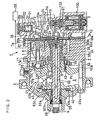
- Fig. 3 is an enlarged longitudinal sectional view of a control valve 100 incorporated into a variable-capacity compressor 1
- Fig. 4 is a longitudinal sectional view of the details of the control valve shown in Fig. 3.
- the control valve 100 is disposed in the spaces 84, 85 of the rear housing 3 of the variable-capacity compressor 1 shown in Figs. 1 and 2 with an airtight state maintained via O- rings 121a, 121b, 131b.
- the solenoid excitation part 130 is provided with a solenoid housing 131 along the periphery thereof. In the interior of this solenoid housing 131, a solenoid 131A, a plunger 133 that moves vertically by the excitation of the solenoid 131A, an attraction element 141, and a stem 138 are disposed. A plunger chamber 130a that houses the plunger 133 communicates with a suction coolant port 129 provided in the control valve body 120.
- the pressure-sensitive part 145 is arranged on the lower side of the solenoid housing 131.
- a bellows 146 and a spring 159 that operate the plunger 133 via the stem 138, etc are disposed.
- the control valve body 120 is provided with a valve chamber 123.
- a valve element 132 that performs opening and closing operations by the plunger 133 is disposed.
- a coolant gas at a high discharge pressure Pd flows into this valve chamber 123 via a passage 81 and a discharge coolant port 126.
- a valve hole 125 that communicates with a crankcase coolant port 128 is formed.
- the space in the upper part of the valve chamber 123 is blocked by a stopper 124.
- apressure chamber 151 opposite to the valve hole 125 is formed.
- This pressure chamber 151 is a bottomed pit having the same sectional area with the valve hole 125.
- This pressure chamber 151 which is a bottomed pit, functions also as a spring-housing chamber 151a and, on the bottom thereof, a valve-closing spring 127 for urging the valve element 132 toward the bottom of the valve chamber 123 is disposed.
- the valve element 132 is composed of an upper portion 132a, an enlarged valve element portion 132b, a small-diameter portion 132c, and a lower portion 132d.
- the valve element 132 takes on the shape of a bar as a whole and the upper portion 132a and lower portion 132d thereof have a sectional area equal to that of the valve hole 125.
- the upper portion 132a is fitted onto and supported by the stopper 124 having the pressure chamber 151.
- the enlarged valve element portion 132b is arranged in the valve chamber 123. Within the valve hole 125, the small-diameter portion 132c is opposed to a crankcase coolant port 128 that communicates with the crankcase (crankcase pressure Pc).
- the plunger 133 that contact-fixes the valve element 132 as shown in Fig. 4 is disposed.
- This plunger 133 is slidably housed in a pipe 136 attached to an end of the control valve body 120 via an O-ring 134a.
- a stem 138 is fixed to the plunger 133, with the upper portion 138A thereof being inserted in a housing hole 137 formed at the lower end of the plunger 133.
- the lower portion 138B of the stem 138 which passes through an upper-end-housing hole 142 of the attraction element 141 and protrudes from the side of a lower-end-housing hole 143, can slide with respect to the attraction element 141.
- a valve-opening spring 144 that urges in a direction in which the valve-opening spring 144 detaches the plunger 133 from the side of the attraction element 141.
- a cord 158 capable of feeding a solenoid current that is controlled by a control computer (not shown) is connected to the solenoid 131A (Fig. 3).
- the rotary power of a car-mounted engine is transmitted to the shaft 5 from a pulley (not shown) via a belt (not shown) .
- the rotary power of the shaft 5 is transmitted to the wobble plate 10 via the thrust flange 40 and hinge mechanism 41 thereby to rotate the wobble plate 10.
- the shoe 50 By the rotation of the wobble plate 10, the shoe 50 performs relative rotation on the sliding surface 10a of the wobble plate 10. As a result, the piston 7 performs linear reciprocating motions and changes the volume of the compression chamber 82 in the cylinder bore 6. According to this volume change of the compression chamber 82 the suction, compression and discharge processes of a coolant gas are sequentially performed and the coolant gas of a volume corresponding to the inclination angle of the wobble plate 10 is delivered.
- the low-temperature coolant gas is introduced into the pressure-sensitive part 145 from the side of the passage 80 (Fig. 3) that communicates with the suction chamber 13 via the suction coolant port 129 of the control valve body 120 and the plunger chamber 130a.
- the bellows 146 of the pressure-sensitive part 145 displaces on the basis of the coolant gas pressure that is the suction pressure Ps of the suction chamber 13. The displacement of this bellows 146 is transmitted to the valve element 132 via the stem 138 and plunger 133.
- the opening of the valve hole 125 by the valve element 132 is determined by the attractive force of the solenoid 131A, the urging force of the bellows 146 and the urging force of the valve-closing spring 127 and of the valve-opening spring 144.
- the bellows 146 contracts and the movement of the valve element 132 responds to this displacement of the bellows 146 (the direction of displacement of the valve element 132 corresponds to the direction of attraction of the plunger 133 by the solenoid 131A), whereby the opening of the valve hole 125 is reduced.
- the volume of the high-pressure coolant gas introduced from the discharge chamber 12 into the valve chamber 123 decreases (the crankcase pressure Pc drops) and the inclination angle of the wobble plate 10 increases (Fig. 1).
- the boss 10b of the wobble plate 10 almost blocks the hole 58c of the ring 9 and substantially reduces the passage sectional area of the first passage 58.
- the coolant gas in the crankcase 8 flows out toward the suction chamber 13 via the third passage 60, an excessive pressure increase in the crankcase 8 is suppressed and it becomes possible for the coolant gas in the compressor 1 to circulate.
- the coolant gas flows through the suction chamber 13, compression chamber 82, discharge chamber 12, second passage 57, crankcase 8 and third passage 60, and returns to the suction chamber 13 again.
- the control valve 100 shown in Fig. 3 and 4 is constituted by the solenoid excitation part 130, which is provided, at the middle thereof, with the plunger 133 moving vertically by the excitation of the solenoid 131A, the pressure-sensitive part 145, in which the bellows 146 operating synchronously with the plunger 133 via the stem 138, etc. is disposed on the lower side of the solenoid excitation part 130, and the control valve body 120 that has the valve chamber 123 in which the valve element 132 operating synchronously with the plunger 133, etc., are disposed on the upper side of the solenoid housing 131.
- the cylindrical portion 141b of the attraction element 141 is, from the lower side thereof, engaged to the adjusting screw 157 and, on the other hand, from the upper side thereof, a stopper 148, a spring 159, a bellows 146 and a flange 149 of the stopper 148, and a spring 150 are installed.
- a cover portion 141c is press-fitted.
- a joint between the cylindrical portion 141b and the cover portion 141c is TIG welded and a pressure-sensitive chamber 145a is formed inside the attraction element 141.
- the adjusting screw 157 is intended for use in the adjustment of the displacement of the bellows 146 by the adjustment of the position of the stopper 148 from the outside.
- a plunger 133 is provided with a coolant vent 133f in the interior thereof in the longitudinal direction and is also provided with a slit 133a for introducing the coolant at the suction pressure Ps into the pressure-sensitive part 145 in the outer surface thereof in the longitudinal direction. Furthermore, a stem 140 having an almost half-moon section is used in the control valve 100 according to the second example. Therefore, the coolant gas at the suction pressure Ps in the plunger chamber 130a is introduced into the pressure-sensitive part 145 via the slit 133a of plunger 133 and the stem 140.
- control valves in the first and second embodiments of the invention are provided.
- FIGS. 6A and 6B and FIGS. 7A to 7C the same reference numerals shown in FIGS. 6A and 6B as those shown in FIG. 5 denote the same members.
- the coil assembly 180 is fixed to the solenoid housing 161 by caulking ( see reference numeral 161C).
- control valve 100 of this embodiment is desirable also from the standpoint of the sealing capacity such as waterproof property and airtightness of the solenoid excitation part.
- a pressure-sensitive part 145 has an adjusting screw 157, which is provided so as to permit an adjustment of forward and backward movement with respect to a frame supporting the pressure-sensitive part 145, i.e., an attraction element 141, and sensitivity can be adjusted by expanding and contracting a pressure-sensitive element, i.e., a bellows 146 by means of this adjusting screw 157. Furthermore, the adjusting screw 157 engages against an engagement part 181 annexed to a coil assembly 180 which constituting a solenoid excitation part 130.
- a solenoid housing 161 is provided at an outer periphery of the solenoid excitation part 130 and supports the coil assembly 180 through an O-ring 190 disposed in an engagement shoulder portion 181a of the coil assembly 180.
- a ring-mounting recess 183 with a notched section is formed in an outer periphery of the above-described coil assembly 180.
- the solenoid housing 161 opposed to this ring-mounting recess 183 is provided with a lid part 161c which is formed in an end of the solenoid housing through a bending part 161b.
- Reference numeral 191 denotes iron plate constituting a magnetic circuit.
- control valve 100 is configured in such a manner that by rotating the coil assembly 180 with respect to the attraction element 141, the adjusting screw 157 is rotated and the bellows 146 is expanded and contracted. And after the bellows 146 is set at an appropriate length, the O-ring 190 is disposed in the ring-mounting recess 183.
- the coil assembly 180 may be rotated with respect to the attraction element 141 after the O-ring 190 is disposed in the ring-mounting recess 183.
- the connector 182 is integrally formed (molded) with the coil assembly 180 by use of a synthetic resin.
- a plurality of, for example, four projections 161d digging into the coil assembly 180 be formed at equal intervals in an edge portion of the lid part 161c so that the plurality of projections 161d engage with the coil assembly 180 in a dug-in condition, as shown in FIGS. 9A and 9B.
- the control valve 100 of the second embodiment of the invention is desirable also from the standpoint of the sealing capacity such as waterproof property and airtightness of the solenoid excitation part.
- control valve body 120 of the control valve 100 and the solenoid excitation part 130 in this embodiment are configured in such a manner that the control valve body 120 is integrally formed with the solenoid excitation part 130 by being screwed from above into a large-thickness portion 161a formed in the upper part of the solenoid housing 161 (see a screwing part 121c).
- the number of parts of the whole control valve decreases, ensuring positive and simple mounting of the control valve body 120 on the solenoid excitation part 130.
- the shape of the adjusting screw is changed and an assembling direction from above is adopted, the assembling efficiency can be improved. Also, there is an advantage that magnetic leakage can be reduced.
- control valve of this embodiment can also be applied to a case where a bellows is not used as the pressure-sensitive element. Furthermore, it is needless to say that the control valve of this embodiment can also be applied to a case where the frame supporting the pressure-sensitive part 145 is a frame other than the attraction element 141.
Landscapes
- Engineering & Computer Science (AREA)
- Mechanical Engineering (AREA)
- General Engineering & Computer Science (AREA)
- Compressors, Vaccum Pumps And Other Relevant Systems (AREA)
- Control Of Positive-Displacement Pumps (AREA)
- Applications Or Details Of Rotary Compressors (AREA)
- Compressor (AREA)
Abstract
Description
Incidentally, the
Claims (8)
- A control valve for variable-capacity compressor which comprises a control valve body, a solenoid excitation part, and a pressure-sensitive part having a pressure-sensitive element; wherein
the sensitivity of said pressure-sensitive element is adjusted by an adjusting screw provided so as to permit an adjustment of forward and backward movement with respect to a frame supporting said pressure-sensitive part, and
the adjusting screw is rotationally operated by engaging an engagement part annexed to a coil assembly constituting said solenoid excitation part against said adjusting screw thereby to operate the coil assembly. - The control valve for variable-capacity compressor according to claim 1, wherein a connector of the solenoid excitation part is formed integrally with said coil assembly by use of a synthetic resin.
- The control valve for variable-capacity compressor according to claim 1, wherein a bellows is disposed as said pressure-sensitive element, the frame supporting said pressure-sensitive part is constituted by an attraction element, and the bellows is expanded and contracted by means of an adjusting screw provided so as to permit an adjustment of forward and backward movement with respect to this attraction element.
- The control valve for variable-capacity compressor according to claim 3, wherein the bellows is expanded and contracted by rotating the coil assembly or connector with respect to said attraction element.
- The control valve for variable-capacity compressor according to claim 1, wherein a solenoid housing is provided at an outer periphery of said solenoid excitation part, and, for mounting said coil assembly on said solenoid housing through an O-ring, a ring-mounting recess with a notched section is formed in an outer periphery of said coil assembly and the solenoid housing opposed to said ring-mounting recess is provided with a lid part formed in an end of the solenoid housing through a bending part.
- The control valve for variable-capacity compressor according to claim 5, wherein a plurality of projections digging into the coil assembly are formed in an edge portion of said lid part.
- The control valve for variable-capacity compressor according to claim 5, wherein the frame supporting said pressure-sensitive part is constituted by an attraction element, and the bellows is expanded and contracted by means of an adjusting screw provided so as to permit an adjustment of forward and backward movement with respect to this attraction element.
- The control valve for variable-capacity compressor according to claim 5, wherein the bellows is expanded and contracted by rotating the coil assembly or connector with respect to said attraction element.
Applications Claiming Priority (4)
| Application Number | Priority Date | Filing Date | Title |
|---|---|---|---|
| JP2001367630 | 2001-11-30 | ||
| JP2001367630A JP3461343B2 (en) | 2001-11-30 | 2001-11-30 | Control valve for variable displacement compressor |
| JP2002134578A JP2003328935A (en) | 2002-05-09 | 2002-05-09 | Control valve for variable displacement compressor |
| JP2002134578 | 2002-05-09 |
Publications (3)
| Publication Number | Publication Date |
|---|---|
| EP1316726A2 true EP1316726A2 (en) | 2003-06-04 |
| EP1316726A3 EP1316726A3 (en) | 2003-11-26 |
| EP1316726B1 EP1316726B1 (en) | 2007-06-27 |
Family
ID=26624816
Family Applications (1)
| Application Number | Title | Priority Date | Filing Date |
|---|---|---|---|
| EP02258271A Expired - Lifetime EP1316726B1 (en) | 2001-11-30 | 2002-11-29 | Control valve for variable-capacity compressor |
Country Status (5)
| Country | Link |
|---|---|
| US (1) | US6769667B2 (en) |
| EP (1) | EP1316726B1 (en) |
| KR (1) | KR100858604B1 (en) |
| AT (1) | ATE365869T1 (en) |
| DE (1) | DE60220873T2 (en) |
Cited By (4)
| Publication number | Priority date | Publication date | Assignee | Title |
|---|---|---|---|---|
| WO2004059166A1 (en) * | 2002-12-24 | 2004-07-15 | Zexel Valeo Climate Control Corporation | Control valve for variable capacity compressor |
| EP1520987A1 (en) * | 2003-09-30 | 2005-04-06 | Fujikoki Corporation | Valve |
| EP1783869A4 (en) * | 2004-08-06 | 2007-12-05 | Sanden Corp | Connector |
| CN112513461A (en) * | 2018-08-08 | 2021-03-16 | 伊格尔工业股份有限公司 | Capacity control valve |
Families Citing this family (11)
| Publication number | Priority date | Publication date | Assignee | Title |
|---|---|---|---|---|
| KR100858604B1 (en) * | 2001-11-30 | 2008-09-17 | 가부시기가이샤 후지고오키 | Control Valve for Variable Capacity Compressors |
| JP4152674B2 (en) * | 2002-06-04 | 2008-09-17 | 株式会社テージーケー | Capacity control valve for variable capacity compressor |
| JP4456906B2 (en) * | 2004-03-25 | 2010-04-28 | 株式会社不二工機 | Control valve for variable capacity compressor |
| JP4714626B2 (en) * | 2006-04-13 | 2011-06-29 | 株式会社不二工機 | Control valve for variable displacement compressor |
| WO2009096968A1 (en) * | 2008-01-31 | 2009-08-06 | Carrier Corporation | Rapid compressor cycling |
| JP4924464B2 (en) * | 2008-02-05 | 2012-04-25 | 株式会社豊田自動織機 | Swash plate compressor |
| SG177507A1 (en) * | 2009-07-06 | 2012-02-28 | Carrier Corp | Bypass unloader valve for compressor capacity control |
| JP2012026311A (en) * | 2010-07-21 | 2012-02-09 | Fuji Koki Corp | Control valve for variable displacement compressor |
| US20150068628A1 (en) * | 2012-05-24 | 2015-03-12 | Eagle Industry Co., Ltd. | Capacity control valve |
| JP6600603B2 (en) * | 2016-06-28 | 2019-10-30 | 株式会社不二工機 | Control valve for variable displacement compressor and assembly method thereof |
| JP6600604B2 (en) * | 2016-06-28 | 2019-10-30 | 株式会社不二工機 | Control valve for variable displacement compressor |
Family Cites Families (17)
| Publication number | Priority date | Publication date | Assignee | Title |
|---|---|---|---|---|
| JPS6329067A (en) * | 1986-07-21 | 1988-02-06 | Sanden Corp | Oscillating type continuously variable displacement compressor |
| JPH01177466A (en) * | 1987-12-28 | 1989-07-13 | Diesel Kiki Co Ltd | Pressure control valve for variable capacity type oscillating plate type compressor |
| JP2567947B2 (en) * | 1989-06-16 | 1996-12-25 | 株式会社豊田自動織機製作所 | Variable capacity compressor |
| JP3245035B2 (en) * | 1996-01-19 | 2002-01-07 | 三菱電機株式会社 | Air control valve |
| JP3432994B2 (en) * | 1996-04-01 | 2003-08-04 | 株式会社豊田自動織機 | Control valve for variable displacement compressor |
| JP3784134B2 (en) * | 1997-05-14 | 2006-06-07 | 株式会社豊田自動織機 | Control valve |
| JP4160669B2 (en) * | 1997-11-28 | 2008-10-01 | 株式会社不二工機 | Control valve for variable displacement compressor |
| JP3783434B2 (en) * | 1998-04-13 | 2006-06-07 | 株式会社豊田自動織機 | Variable capacity swash plate compressor and air conditioning cooling circuit |
| JP3583951B2 (en) * | 1999-06-07 | 2004-11-04 | 株式会社豊田自動織機 | Capacity control valve |
| JP2001041154A (en) * | 1999-07-26 | 2001-02-13 | Zexel Valeo Climate Control Corp | Control valve for variable-displacement compressor |
| JP2001082325A (en) * | 1999-09-16 | 2001-03-27 | Zexel Valeo Climate Control Corp | Control valve for variable displacement compressor |
| JP2001099060A (en) * | 1999-10-04 | 2001-04-10 | Fuji Koki Corp | Control valve for variable displacement compressor |
| JP4205826B2 (en) * | 1999-11-30 | 2009-01-07 | 株式会社不二工機 | Control valve for variable displacement compressor |
| JP4829419B2 (en) * | 2001-04-06 | 2011-12-07 | 株式会社不二工機 | Control valve for variable displacement compressor |
| KR100858604B1 (en) * | 2001-11-30 | 2008-09-17 | 가부시기가이샤 후지고오키 | Control Valve for Variable Capacity Compressors |
| JP3461343B2 (en) * | 2001-11-30 | 2003-10-27 | 株式会社不二工機 | Control valve for variable displacement compressor |
| JP2003328935A (en) * | 2002-05-09 | 2003-11-19 | Fuji Koki Corp | Control valve for variable displacement compressor |
-
2002
- 2002-10-29 KR KR1020020066052A patent/KR100858604B1/en not_active Expired - Fee Related
- 2002-11-22 US US10/301,842 patent/US6769667B2/en not_active Expired - Lifetime
- 2002-11-29 EP EP02258271A patent/EP1316726B1/en not_active Expired - Lifetime
- 2002-11-29 DE DE60220873T patent/DE60220873T2/en not_active Expired - Lifetime
- 2002-11-29 AT AT02258271T patent/ATE365869T1/en not_active IP Right Cessation
Cited By (6)
| Publication number | Priority date | Publication date | Assignee | Title |
|---|---|---|---|---|
| WO2004059166A1 (en) * | 2002-12-24 | 2004-07-15 | Zexel Valeo Climate Control Corporation | Control valve for variable capacity compressor |
| EP1520987A1 (en) * | 2003-09-30 | 2005-04-06 | Fujikoki Corporation | Valve |
| EP1783869A4 (en) * | 2004-08-06 | 2007-12-05 | Sanden Corp | Connector |
| CN1993868B (en) * | 2004-08-06 | 2012-07-04 | 三电有限公司 | Connector |
| CN112513461A (en) * | 2018-08-08 | 2021-03-16 | 伊格尔工业股份有限公司 | Capacity control valve |
| CN112513461B (en) * | 2018-08-08 | 2022-12-23 | 伊格尔工业股份有限公司 | Capacity control valve |
Also Published As
| Publication number | Publication date |
|---|---|
| DE60220873D1 (en) | 2007-08-09 |
| KR20030044784A (en) | 2003-06-09 |
| EP1316726B1 (en) | 2007-06-27 |
| KR100858604B1 (en) | 2008-09-17 |
| ATE365869T1 (en) | 2007-07-15 |
| DE60220873T2 (en) | 2008-03-06 |
| EP1316726A3 (en) | 2003-11-26 |
| US20030102454A1 (en) | 2003-06-05 |
| US6769667B2 (en) | 2004-08-03 |
Similar Documents
| Publication | Publication Date | Title |
|---|---|---|
| EP1247981B1 (en) | Control valve for variable capacity compressors | |
| EP1316726B1 (en) | Control valve for variable-capacity compressor | |
| US6485267B1 (en) | Control valve for variable capacity compressors | |
| KR100987042B1 (en) | Capacity control valve in variable displacement compressor | |
| US8021124B2 (en) | Capacity control valve | |
| JP3131036B2 (en) | Solenoid proportional control valve | |
| KR100291521B1 (en) | Control Valves for Variable Capacity Compressors | |
| CN110582641A (en) | Solenoid control valve and variable capacity compressor including the same | |
| JPH05288150A (en) | Solenoid control valve | |
| US5975859A (en) | Control valve in variable displacement compressor and its assembling method | |
| KR20150101963A (en) | Control valve for variable displacement compressor | |
| EP3744976B1 (en) | Capacity control valve | |
| US6280152B1 (en) | Variable-type swash plate compressor having a cock member for fixed capacity operation and manufacturing method therefor | |
| AU657954B2 (en) | Slant plate type compressor with variable displacement mechanism | |
| KR102252391B1 (en) | Variable displacement compressor and control valve thereof | |
| EP0260667B1 (en) | Slant plate type compressor with variable displacement mechanism | |
| JP3461343B2 (en) | Control valve for variable displacement compressor | |
| JP4173980B2 (en) | Control valve for variable capacity compressor | |
| JP4082802B2 (en) | Control valve for variable displacement compressor | |
| EP1182348B1 (en) | Clutchless compressor control valve with integral by pass feature | |
| JP3847617B2 (en) | Control valve for variable capacity compressor | |
| JP4247225B2 (en) | Control valve for variable capacity compressor | |
| JP2006118508A5 (en) | ||
| JP2003328935A (en) | Control valve for variable displacement compressor | |
| JP2001041154A (en) | Control valve for variable-displacement compressor |
Legal Events
| Date | Code | Title | Description |
|---|---|---|---|
| PUAI | Public reference made under article 153(3) epc to a published international application that has entered the european phase |
Free format text: ORIGINAL CODE: 0009012 |
|
| AK | Designated contracting states |
Designated state(s): AT BE BG CH CY CZ DE DK EE ES FI FR GB GR IE IT LI LU MC NL PT SE SK TR |
|
| AX | Request for extension of the european patent |
Extension state: AL LT LV MK RO SI |
|
| PUAL | Search report despatched |
Free format text: ORIGINAL CODE: 0009013 |
|
| AK | Designated contracting states |
Kind code of ref document: A3 Designated state(s): AT BE BG CH CY CZ DE DK EE ES FI FR GB GR IE IT LI LU MC NL PT SE SK TR |
|
| AX | Request for extension of the european patent |
Extension state: AL LT LV MK RO SI |
|
| 17P | Request for examination filed |
Effective date: 20040430 |
|
| AKX | Designation fees paid |
Designated state(s): AT BE BG CH CY CZ DE DK EE ES FI FR GB GR IE IT LI LU MC NL PT SE SK TR |
|
| AXX | Extension fees paid |
Extension state: AL Payment date: 20021223 Extension state: LV Payment date: 20021223 Extension state: RO Payment date: 20021223 Extension state: LT Payment date: 20021223 Extension state: SI Payment date: 20021223 Extension state: MK Payment date: 20021223 |
|
| GRAP | Despatch of communication of intention to grant a patent |
Free format text: ORIGINAL CODE: EPIDOSNIGR1 |
|
| GRAS | Grant fee paid |
Free format text: ORIGINAL CODE: EPIDOSNIGR3 |
|
| GRAA | (expected) grant |
Free format text: ORIGINAL CODE: 0009210 |
|
| AK | Designated contracting states |
Kind code of ref document: B1 Designated state(s): AT BE BG CH CY CZ DE DK EE ES FI FR GB GR IE IT LI LU MC NL PT SE SK TR |
|
| AX | Request for extension of the european patent |
Extension state: AL LT LV MK RO SI |
|
| REG | Reference to a national code |
Ref country code: GB Ref legal event code: FG4D |
|
| REG | Reference to a national code |
Ref country code: CH Ref legal event code: EP |
|
| REG | Reference to a national code |
Ref country code: IE Ref legal event code: FG4D |
|
| REF | Corresponds to: |
Ref document number: 60220873 Country of ref document: DE Date of ref document: 20070809 Kind code of ref document: P |
|
| PG25 | Lapsed in a contracting state [announced via postgrant information from national office to epo] |
Ref country code: SE Free format text: LAPSE BECAUSE OF FAILURE TO SUBMIT A TRANSLATION OF THE DESCRIPTION OR TO PAY THE FEE WITHIN THE PRESCRIBED TIME-LIMIT Effective date: 20070927 |
|
| PG25 | Lapsed in a contracting state [announced via postgrant information from national office to epo] |
Ref country code: AT Free format text: LAPSE BECAUSE OF FAILURE TO SUBMIT A TRANSLATION OF THE DESCRIPTION OR TO PAY THE FEE WITHIN THE PRESCRIBED TIME-LIMIT Effective date: 20070627 |
|
| NLV1 | Nl: lapsed or annulled due to failure to fulfill the requirements of art. 29p and 29m of the patents act | ||
| LTIE | Lt: invalidation of european patent or patent extension |
Effective date: 20070627 |
|
| ET | Fr: translation filed | ||
| REG | Reference to a national code |
Ref country code: CH Ref legal event code: PL |
|
| PG25 | Lapsed in a contracting state [announced via postgrant information from national office to epo] |
Ref country code: BE Free format text: LAPSE BECAUSE OF FAILURE TO SUBMIT A TRANSLATION OF THE DESCRIPTION OR TO PAY THE FEE WITHIN THE PRESCRIBED TIME-LIMIT Effective date: 20070627 |
|
| PG25 | Lapsed in a contracting state [announced via postgrant information from national office to epo] |
Ref country code: CZ Free format text: LAPSE BECAUSE OF FAILURE TO SUBMIT A TRANSLATION OF THE DESCRIPTION OR TO PAY THE FEE WITHIN THE PRESCRIBED TIME-LIMIT Effective date: 20070627 Ref country code: ES Free format text: LAPSE BECAUSE OF FAILURE TO SUBMIT A TRANSLATION OF THE DESCRIPTION OR TO PAY THE FEE WITHIN THE PRESCRIBED TIME-LIMIT Effective date: 20071008 Ref country code: PT Free format text: LAPSE BECAUSE OF FAILURE TO SUBMIT A TRANSLATION OF THE DESCRIPTION OR TO PAY THE FEE WITHIN THE PRESCRIBED TIME-LIMIT Effective date: 20071127 Ref country code: NL Free format text: LAPSE BECAUSE OF FAILURE TO SUBMIT A TRANSLATION OF THE DESCRIPTION OR TO PAY THE FEE WITHIN THE PRESCRIBED TIME-LIMIT Effective date: 20070627 Ref country code: BG Free format text: LAPSE BECAUSE OF FAILURE TO SUBMIT A TRANSLATION OF THE DESCRIPTION OR TO PAY THE FEE WITHIN THE PRESCRIBED TIME-LIMIT Effective date: 20070927 |
|
| PG25 | Lapsed in a contracting state [announced via postgrant information from national office to epo] |
Ref country code: SK Free format text: LAPSE BECAUSE OF FAILURE TO SUBMIT A TRANSLATION OF THE DESCRIPTION OR TO PAY THE FEE WITHIN THE PRESCRIBED TIME-LIMIT Effective date: 20070627 Ref country code: LI Free format text: LAPSE BECAUSE OF FAILURE TO SUBMIT A TRANSLATION OF THE DESCRIPTION OR TO PAY THE FEE WITHIN THE PRESCRIBED TIME-LIMIT Effective date: 20070627 Ref country code: CH Free format text: LAPSE BECAUSE OF FAILURE TO SUBMIT A TRANSLATION OF THE DESCRIPTION OR TO PAY THE FEE WITHIN THE PRESCRIBED TIME-LIMIT Effective date: 20070627 |
|
| PG25 | Lapsed in a contracting state [announced via postgrant information from national office to epo] |
Ref country code: GR Free format text: LAPSE BECAUSE OF FAILURE TO SUBMIT A TRANSLATION OF THE DESCRIPTION OR TO PAY THE FEE WITHIN THE PRESCRIBED TIME-LIMIT Effective date: 20070928 Ref country code: DK Free format text: LAPSE BECAUSE OF FAILURE TO SUBMIT A TRANSLATION OF THE DESCRIPTION OR TO PAY THE FEE WITHIN THE PRESCRIBED TIME-LIMIT Effective date: 20070627 |
|
| PLBE | No opposition filed within time limit |
Free format text: ORIGINAL CODE: 0009261 |
|
| STAA | Information on the status of an ep patent application or granted ep patent |
Free format text: STATUS: NO OPPOSITION FILED WITHIN TIME LIMIT |
|
| 26N | No opposition filed |
Effective date: 20080328 |
|
| PG25 | Lapsed in a contracting state [announced via postgrant information from national office to epo] |
Ref country code: MC Free format text: LAPSE BECAUSE OF NON-PAYMENT OF DUE FEES Effective date: 20071130 |
|
| PG25 | Lapsed in a contracting state [announced via postgrant information from national office to epo] |
Ref country code: IE Free format text: LAPSE BECAUSE OF NON-PAYMENT OF DUE FEES Effective date: 20071129 |
|
| PG25 | Lapsed in a contracting state [announced via postgrant information from national office to epo] |
Ref country code: EE Free format text: LAPSE BECAUSE OF FAILURE TO SUBMIT A TRANSLATION OF THE DESCRIPTION OR TO PAY THE FEE WITHIN THE PRESCRIBED TIME-LIMIT Effective date: 20070627 |
|
| PG25 | Lapsed in a contracting state [announced via postgrant information from national office to epo] |
Ref country code: FI Free format text: LAPSE BECAUSE OF FAILURE TO SUBMIT A TRANSLATION OF THE DESCRIPTION OR TO PAY THE FEE WITHIN THE PRESCRIBED TIME-LIMIT Effective date: 20070627 |
|
| REG | Reference to a national code |
Ref country code: GB Ref legal event code: 746 Effective date: 20090408 |
|
| PG25 | Lapsed in a contracting state [announced via postgrant information from national office to epo] |
Ref country code: CY Free format text: LAPSE BECAUSE OF FAILURE TO SUBMIT A TRANSLATION OF THE DESCRIPTION OR TO PAY THE FEE WITHIN THE PRESCRIBED TIME-LIMIT Effective date: 20070627 |
|
| PG25 | Lapsed in a contracting state [announced via postgrant information from national office to epo] |
Ref country code: LU Free format text: LAPSE BECAUSE OF NON-PAYMENT OF DUE FEES Effective date: 20071129 |
|
| PG25 | Lapsed in a contracting state [announced via postgrant information from national office to epo] |
Ref country code: TR Free format text: LAPSE BECAUSE OF FAILURE TO SUBMIT A TRANSLATION OF THE DESCRIPTION OR TO PAY THE FEE WITHIN THE PRESCRIBED TIME-LIMIT Effective date: 20070627 |
|
| REG | Reference to a national code |
Ref country code: FR Ref legal event code: PLFP Year of fee payment: 14 |
|
| PG25 | Lapsed in a contracting state [announced via postgrant information from national office to epo] |
Ref country code: IT Free format text: LAPSE BECAUSE OF NON-PAYMENT OF DUE FEES Effective date: 20151129 |
|
| REG | Reference to a national code |
Ref country code: FR Ref legal event code: PLFP Year of fee payment: 15 |
|
| PG25 | Lapsed in a contracting state [announced via postgrant information from national office to epo] |
Ref country code: IT Free format text: LAPSE BECAUSE OF NON-PAYMENT OF DUE FEES Effective date: 20151129 |
|
| PGRI | Patent reinstated in contracting state [announced from national office to epo] |
Ref country code: IT Effective date: 20161122 |
|
| REG | Reference to a national code |
Ref country code: FR Ref legal event code: PLFP Year of fee payment: 16 |
|
| REG | Reference to a national code |
Ref country code: FR Ref legal event code: PLFP Year of fee payment: 17 |
|
| PGFP | Annual fee paid to national office [announced via postgrant information from national office to epo] |
Ref country code: DE Payment date: 20181113 Year of fee payment: 17 |
|
| PGFP | Annual fee paid to national office [announced via postgrant information from national office to epo] |
Ref country code: FR Payment date: 20181011 Year of fee payment: 17 Ref country code: IT Payment date: 20181122 Year of fee payment: 17 Ref country code: GB Payment date: 20181128 Year of fee payment: 17 |
|
| REG | Reference to a national code |
Ref country code: DE Ref legal event code: R119 Ref document number: 60220873 Country of ref document: DE |
|
| GBPC | Gb: european patent ceased through non-payment of renewal fee |
Effective date: 20191129 |
|
| PG25 | Lapsed in a contracting state [announced via postgrant information from national office to epo] |
Ref country code: DE Free format text: LAPSE BECAUSE OF NON-PAYMENT OF DUE FEES Effective date: 20200603 Ref country code: GB Free format text: LAPSE BECAUSE OF NON-PAYMENT OF DUE FEES Effective date: 20191129 Ref country code: IT Free format text: LAPSE BECAUSE OF NON-PAYMENT OF DUE FEES Effective date: 20191129 Ref country code: FR Free format text: LAPSE BECAUSE OF NON-PAYMENT OF DUE FEES Effective date: 20191130 |