EP1316715A2 - Injection-molded air intake manifold for a V-style engine - Google Patents
Injection-molded air intake manifold for a V-style engine Download PDFInfo
- Publication number
- EP1316715A2 EP1316715A2 EP02079652A EP02079652A EP1316715A2 EP 1316715 A2 EP1316715 A2 EP 1316715A2 EP 02079652 A EP02079652 A EP 02079652A EP 02079652 A EP02079652 A EP 02079652A EP 1316715 A2 EP1316715 A2 EP 1316715A2
- Authority
- EP
- European Patent Office
- Prior art keywords
- intake manifold
- air
- air intake
- accordance
- runners
- Prior art date
- Legal status (The legal status is an assumption and is not a legal conclusion. Google has not performed a legal analysis and makes no representation as to the accuracy of the status listed.)
- Withdrawn
Links
Images


Classifications
-
- F—MECHANICAL ENGINEERING; LIGHTING; HEATING; WEAPONS; BLASTING
- F02—COMBUSTION ENGINES; HOT-GAS OR COMBUSTION-PRODUCT ENGINE PLANTS
- F02M—SUPPLYING COMBUSTION ENGINES IN GENERAL WITH COMBUSTIBLE MIXTURES OR CONSTITUENTS THEREOF
- F02M35/00—Combustion-air cleaners, air intakes, intake silencers, or induction systems specially adapted for, or arranged on, internal-combustion engines
- F02M35/10—Air intakes; Induction systems
- F02M35/1034—Manufacturing and assembling intake systems
- F02M35/10347—Moulding, casting or the like
-
- F—MECHANICAL ENGINEERING; LIGHTING; HEATING; WEAPONS; BLASTING
- F02—COMBUSTION ENGINES; HOT-GAS OR COMBUSTION-PRODUCT ENGINE PLANTS
- F02B—INTERNAL-COMBUSTION PISTON ENGINES; COMBUSTION ENGINES IN GENERAL
- F02B75/00—Other engines
- F02B75/16—Engines characterised by number of cylinders, e.g. single-cylinder engines
- F02B75/18—Multi-cylinder engines
- F02B75/22—Multi-cylinder engines with cylinders in V, fan, or star arrangement
-
- F—MECHANICAL ENGINEERING; LIGHTING; HEATING; WEAPONS; BLASTING
- F02—COMBUSTION ENGINES; HOT-GAS OR COMBUSTION-PRODUCT ENGINE PLANTS
- F02M—SUPPLYING COMBUSTION ENGINES IN GENERAL WITH COMBUSTIBLE MIXTURES OR CONSTITUENTS THEREOF
- F02M35/00—Combustion-air cleaners, air intakes, intake silencers, or induction systems specially adapted for, or arranged on, internal-combustion engines
- F02M35/10—Air intakes; Induction systems
- F02M35/10006—Air intakes; Induction systems characterised by the position of elements of the air intake system in direction of the air intake flow, i.e. between ambient air inlet and supply to the combustion chamber
- F02M35/10026—Plenum chambers
- F02M35/10045—Multiple plenum chambers; Plenum chambers having inner separation walls
-
- F—MECHANICAL ENGINEERING; LIGHTING; HEATING; WEAPONS; BLASTING
- F02—COMBUSTION ENGINES; HOT-GAS OR COMBUSTION-PRODUCT ENGINE PLANTS
- F02M—SUPPLYING COMBUSTION ENGINES IN GENERAL WITH COMBUSTIBLE MIXTURES OR CONSTITUENTS THEREOF
- F02M35/00—Combustion-air cleaners, air intakes, intake silencers, or induction systems specially adapted for, or arranged on, internal-combustion engines
- F02M35/10—Air intakes; Induction systems
- F02M35/10006—Air intakes; Induction systems characterised by the position of elements of the air intake system in direction of the air intake flow, i.e. between ambient air inlet and supply to the combustion chamber
- F02M35/10026—Plenum chambers
- F02M35/10052—Plenum chambers special shapes or arrangements of plenum chambers; Constructional details
-
- F—MECHANICAL ENGINEERING; LIGHTING; HEATING; WEAPONS; BLASTING
- F02—COMBUSTION ENGINES; HOT-GAS OR COMBUSTION-PRODUCT ENGINE PLANTS
- F02M—SUPPLYING COMBUSTION ENGINES IN GENERAL WITH COMBUSTIBLE MIXTURES OR CONSTITUENTS THEREOF
- F02M35/00—Combustion-air cleaners, air intakes, intake silencers, or induction systems specially adapted for, or arranged on, internal-combustion engines
- F02M35/10—Air intakes; Induction systems
- F02M35/10209—Fluid connections to the air intake system; their arrangement of pipes, valves or the like
- F02M35/10222—Exhaust gas recirculation [EGR]; Positive crankcase ventilation [PCV]; Additional air admission, lubricant or fuel vapour admission
-
- F—MECHANICAL ENGINEERING; LIGHTING; HEATING; WEAPONS; BLASTING
- F02—COMBUSTION ENGINES; HOT-GAS OR COMBUSTION-PRODUCT ENGINE PLANTS
- F02M—SUPPLYING COMBUSTION ENGINES IN GENERAL WITH COMBUSTIBLE MIXTURES OR CONSTITUENTS THEREOF
- F02M35/00—Combustion-air cleaners, air intakes, intake silencers, or induction systems specially adapted for, or arranged on, internal-combustion engines
- F02M35/10—Air intakes; Induction systems
- F02M35/10314—Materials for intake systems
- F02M35/10321—Plastics; Composites; Rubbers
-
- F—MECHANICAL ENGINEERING; LIGHTING; HEATING; WEAPONS; BLASTING
- F02—COMBUSTION ENGINES; HOT-GAS OR COMBUSTION-PRODUCT ENGINE PLANTS
- F02M—SUPPLYING COMBUSTION ENGINES IN GENERAL WITH COMBUSTIBLE MIXTURES OR CONSTITUENTS THEREOF
- F02M35/00—Combustion-air cleaners, air intakes, intake silencers, or induction systems specially adapted for, or arranged on, internal-combustion engines
- F02M35/10—Air intakes; Induction systems
- F02M35/1034—Manufacturing and assembling intake systems
- F02M35/10354—Joining multiple sections together
- F02M35/1036—Joining multiple sections together by welding, bonding or the like
-
- F—MECHANICAL ENGINEERING; LIGHTING; HEATING; WEAPONS; BLASTING
- F02—COMBUSTION ENGINES; HOT-GAS OR COMBUSTION-PRODUCT ENGINE PLANTS
- F02M—SUPPLYING COMBUSTION ENGINES IN GENERAL WITH COMBUSTIBLE MIXTURES OR CONSTITUENTS THEREOF
- F02M35/00—Combustion-air cleaners, air intakes, intake silencers, or induction systems specially adapted for, or arranged on, internal-combustion engines
- F02M35/10—Air intakes; Induction systems
- F02M35/104—Intake manifolds
- F02M35/116—Intake manifolds for engines with cylinders in V-arrangement or arranged oppositely relative to the main shaft
-
- F—MECHANICAL ENGINEERING; LIGHTING; HEATING; WEAPONS; BLASTING
- F05—INDEXING SCHEMES RELATING TO ENGINES OR PUMPS IN VARIOUS SUBCLASSES OF CLASSES F01-F04
- F05C—INDEXING SCHEME RELATING TO MATERIALS, MATERIAL PROPERTIES OR MATERIAL CHARACTERISTICS FOR MACHINES, ENGINES OR PUMPS OTHER THAN NON-POSITIVE-DISPLACEMENT MACHINES OR ENGINES
- F05C2225/00—Synthetic polymers, e.g. plastics; Rubber
- F05C2225/08—Thermoplastics
Definitions
- the present invention relates to intake manifolds for internal combustion engines; more particularly, to such manifolds formed of a polymer; and most particularly, to an intake manifold module formed by vibration welding of a plurality of injection-molded components.
- An internal combustion engine powered by either diesel fuel or gasoline, includes generally an intake manifold assembly for collecting air from outside the engine and distributing the collected air to each of the combustion cylinders.
- the manifold typically is part of a relatively complex assembly known generally in the art as an integrated air/fuel module (IAFM).
- IAFM may include a variety of sub-systems for performing a host of related functions, including, for example, a throttle body and valve for air flow control, a helmholz resonator for noise suppression, an exhaust gas recirculation valve for mixing exhaust gas into the fresh air stream, a fuel rail and fuel injectors for injecting fuel to the cylinders, and a purge valve for stripping fuel from a fuel tank cannister.
- intake manifolds were formed of metal such as cast iron or aluminum by molding around a sand-cast core, a costly manufacturing technique wherein the integrity of the core was destroyed by the heat of the molten metal, allowing the sand to be poured from the interior of the cooled component.
- intake modules are known in the art to be formed of high-temperature thermoplastic composites such as glass-filled nylon or glass-filled polyphthalamide by "lost core" molding, a technique related to sand casting wherein a sacrificial internal core, formed typically of a tin/bismuth alloy having a relatively low melting temperature, is destroyed after the molding process.
- an intake module by less-expensive forming techniques such as injection molding, wherein a component is formed by filling a cavity between an inner and an outer mold.
- the shape of the component must be such that the inner mold can be released and extracted from the part upon solidification of the molding material, a requirement that heretofore has generally dictated use of a sacrificial inner mold.
- injection molding has not been available heretofore for the formation of a satisfactory IAFM for a V-style engine because of 1) very tight tolerances required in bridging across the valley between the left- and right- bank cylinder heads, and 2) great difficulty in reliably welding mating surfaces of components within the module.
- the runners carrying air from a central plenum to the individual cylinders may differ in length and/or geometry, which is undesirable because the various cylinders may experience differing air/fuel ratios. It is preferred that the runners be identical, so that each cylinder is supplied identically with air.
- the present invention is directed to an improved air intake manifold for a V-style internal combustion engine.
- the manifold is assembled from three individual injection molded sections by friction welding of mating surfaces.
- each section is formed of a high-melting temperature composite polymer, such as glass-filled nylon or glass-filled polyphthalamide.
- the mating surfaces are all on the exterior of the manifold and are so formed as to be directly accessible to welding apparatus, including clamping devices. Further, the mating surfaces are so oriented that friction welding may be carried out by relative motion between the components in the axial direction.
- the lower and middle sections form the individual distribution runners from the plenum to the intake ports in the engine heads.
- the lower and middle sections are so configured that each such runner crosses the valley of the engine, providing great strength and rigidity to the module. Further, all runners are identical, so that air flows from the plenum to the individual cylinders are substantially identical.
- the middle and upper sections are rotationally symmetrical about a vertical axis orthogonal to the longitudinal axis of the module, such that each may be added to the module during assembly in either of two orientations 180° apart, making mis-orientation impossible. Modifications may be made to any of the sections, as may be required for example to adapt the manifold to a specific engine IAFM requirement, without requiring retooling of molds for the other two sections, provided the configurations of the mating surfaces are unchanged.
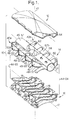
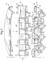
- an improved air intake manifold 10 in accordance with the invention includes an upper section 12, a middle section 14, and a lower section 16, which are assemblable as shown in FIG. 7 to form manifold 10.
- Each of sections 12,14,16 is configured to be formed by injection molding of a suitable thermallyliquefied polymer into an injection mold having inner and outer reusable molds. Formation of these sections does not require a lost-core inner mold, as in the prior art. Auxiliary side slides also may be required, as is known in the art of injection molding.
- molded sections are formed of a high-melting temperature composite polymer, such as glass-filled high-temperature nylon or glass-filled polyphthalamide which are readily available from commercial sources.
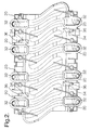
- Lower section 16 having a longitudinal axis 17, includes the lower portions 18 of individual air distribution runners, each terminating distally in a port 20 matable with a corresponding intake port (not shown) in a left or right head 22,24 of a V-style engine 26 (FIG. 6) having an included angle 25 between the heads.
- Heads 22,24 are arranged longitudinally and generally symmetrically about an engine plane of symmetry 27.
- Lower portions terminating in left-head ports are designated 18-22, and lower portions terminating in right-head ports are designated 18-24.
- Each of lower portions 18-22 and 18-24 terminates proximally in an opening fully surrounded by a flange 28 extending axially of portion 18 and having a respective mating surface 30-22 or 30-24.
- all of the mating surfaces 30-22 are coplanar and mating surfaces 30-24 are coplanar, and all are contained in planes or surfaces parallel to axis 17. Adjacent ones of flanges 28 preferably are axially separated by at least about 2 mm.
- all of lower portions 18-22 are identical in size and shape, as are all of lower portions 18-24; and further, portions 18-22 are mirror image configurations of portions 18-24 (when reversed end-for-end).
- Lower section 16 further includes a plurality of injector ports 32, a one of each opening into each of runner ports 20 for receiving a fuel injector (not shown) during final assembly of a finished IAFM.
- Section 16 further includes towers 34 containing bores 36 for receiving mounting screws for fuel rails (not shown) incorporating the fuel injectors, and a plurality of bores 38 for receiving bolts (not shown) for securing section 16 to the engine heads 22,24. Any of various known gasket types (not shown) may be incorporated as desired between section 16 and heads 22,24.
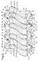
- middle section 14 includes a first bank 40a and a second bank 40b of upper portions 42 of individual air distribution runners 44 disposed along opposite sides of a central zip tube 46.
- Each upper portion 42 crosses beneath zip tube 46 and terminates distally in an opening (not visible in the drawings) and flange 48.
- flange 48 As in the lower element, there are left flanges 48-22 and right flanges 48-24.
- Each flange has a surface substantially identical to and matable with respective lower portion surfaces 30-22,30-24 to form left- and right-runners 44-22,44-24, respectively.
- Each upper portion 42 in banks 40a,40b terminates proximally in an opening 50 in a planar element 52 disposed longitudinally along zip tube 46 in a plane parallel to a plane containing axis 54 of middle section 14. Openings 50a in planar element 52a lead to runners 44-24, and openings 50b in planar element 52b lead to runners 44-22, all runners crossing under tube 46 as previously described and passing through engine symmetry plane 27.
- elements 52a and 52b are not coplanar but rather are mutually inclined in order to properly shape the entrance regions of runners 44.
- middle section 14 is rotationally symmetrical about vertical axis 47 such that section 14 may be oriented either as shown in FIG. 1 or upon 180° rotation about axis 47, to equal effect, such that openings 50a then lead to runners 44-24 and openings 50b lead to runners 44-22.
- Zip tube 46 includes an air intake port 53 at a proximal end 55 and an air exhaust port 56 in a central region of the tube, and may include other ports for auxiliary systems, for example, port 58 for an EGR valve and port 60 for a purge valve in known fashion.
- Intake port 53 may receive a throttle valve body (not shown) in known fashion.
- the distal end 57 of zip tube 46 is closed by a helmholz resonator 62 for damping resonant sonic frequencies in the air intake system.
- upper section 12 is slightly dome-shaped both axially and radially and is provided with a flange 64 configured to mate conformably with zip tube 46 and planar elements 52a,b along the outer edges 66a,b thereof.
- a plenum is created therebetween for receiving intake air from tube exhaust port 56 and distributing the air to runners 44 via openings 50a,b.
- upper section 12 is also preferably rotationally symmetrical about vertical axis 47 and may be installed in either of two 180° opposed orientations.
- Sections 12,14,16 may be joined by any suitable means, as by adhesives or clamps, but preferably by thermal welding of all mating surface, and most preferably by vibration (friction) welding.
- the mating surfaces all lie parallel to the axes of their respective sections.
- each surface may be axially displaced by a small distance relative to its opposite mate.
- Vibration, or friction, welding requires such relative movement, on the order of +/- 1 mm, which is permitted in the axial direction by the careful arrangement of the mating surfaces.
- all mating flanges extend axially from their respective openings such that mating flanges may be captured over their entire lengths between a sonic horn and a back-up tool, thus ensuring highly reliable welding of all surfaces.
- sections 12,14,16 may be die-cast of aluminum or other metal and welded along the outer edges of the respective flanges; however, the injection-molded polymeric embodiment is currently preferred.
Landscapes
- Engineering & Computer Science (AREA)
- Chemical & Material Sciences (AREA)
- Combustion & Propulsion (AREA)
- Mechanical Engineering (AREA)
- General Engineering & Computer Science (AREA)
- Manufacturing & Machinery (AREA)
- Physics & Mathematics (AREA)
- Geometry (AREA)
- Lining Or Joining Of Plastics Or The Like (AREA)
- Injection Moulding Of Plastics Or The Like (AREA)
- Moulds For Moulding Plastics Or The Like (AREA)
Abstract
Description
Claims (18)
- An air intake manifold (10) for collecting ambient air and distributing the air to individual cylinders of a V-style internal combustion engine (26), the manifold comprising a plurality of injection-molded components (12,14,16) joined by welding.
- An air intake manifold (10) in accordance with Claim 1 wherein said components are formed of a high-melting temperature polymer.
- An air intake manifold (10) in accordance with Claim 2 wherein said polymer is a polymer composite selected from the group consisting of glass-filled nylon and glass-filled polyphthalamide.
- An air intake manifold (10) in accordance with Claim 1 wherein said welding is caused by sliding friction between said components.
- An air intake manifold (10) in accordance with Claim 1 wherein said engine is a V-8.
- An air intake manifold (10) in accordance with Claim 1 wherein said manifold comprises:a) a lower section (16) including lower portions (18) of air distribution runners (44);b) a middle section (14) including upper portions (42) of said air distribution runners, said upper portions cooperating with said lower portions to form said runners to distribute air to said engine cylinders; andc) an upper section (12) for cooperating with said middle section to form a plenum (52) for distributing air to said runners (44).
- An air intake manifold (10) in accordance with Claim 6 wherein the size and configuration of said runners are identical for all of said runners (44).
- An air intake manifold (10) in accordance with Claim 6 wherein said V-style engine has a plane of symmetry (27), and wherein said engine has left and right heads (22,24) disposed on opposite sides of said plane (27), and wherein each of said runners (44) passes through said plane in distributing air from said plenum (52) to said engine cylinders.
- An air intake manifold (10) in accordance with Claim 6 wherein said middle section (14) includes a helmholz resonator (62).
- An air intake manifold (10) in accordance with Claim 6 wherein all of said welds are formed on outer surfaces (28,48,64,66) of said sections.
- An air intake manifold (10) in accordance with Claim 10 wherein said sections (14,16) are provided with mating surfaces (30) for being conjoined by welding and wherein said sections include flanges (28,48) adjacent said mating surfaces for engagement by welding apparatus to facilitate said conjoining.
- An air intake manifold (10) in accordance with Claim 11 wherein said mating surfaces (30) are oriented such that said sections may oscillate with respect to each other in an axial direction during said welding process.
- An air intake manifold (10) in accordance with Claim 6 wherein said middle section (14) is rotationally symmetrical about an axis (47) orthogonal to a longitudinal axis (54) thereof.
- An air intake manifold (10) in accordance with Claim 6 wherein said upper section (12) is rotationally symmetrical about an axis (47) orthogonal to a longitudinal axis (54) thereof.
- An air intake manifold (10) in accordance with Claim 6 further comprising a zip tube (46) integrally molded into said middle section.
- A V-style internal combustion engine (26) having an air intake manifold (10) comprising a plurality of injection-molded components (12,14,16) joined by welding.
- An engine (26) in accordance with Claim 16 wherein said manifold comprises:a) a lower section (16) including lower portions (18) of air distribution runners (44);b) a middle section (14) including upper portions (42) of said air distribution runners and a zip tube (46), said upper portions (42) cooperating with said lower portions (18) to form said runners to distribute air to engine cylinders; andc) an upper section (12) for cooperating with said middle section to form a plenum (52) for distributing air from said zip tube (46) to said runners (44).
- An air intake manifold (10) for collecting ambient air, combining the air with injected fuel, and distributing the air to individual cylinders of a V-style internal combustion engine (26), the module comprising a plurality of die-cast metal components (12,14,16) joined by welding.
Applications Claiming Priority (2)
| Application Number | Priority Date | Filing Date | Title |
|---|---|---|---|
| US09/998,252 US6679215B2 (en) | 2001-11-30 | 2001-11-30 | Injection-molded air intake manifold for a V-style engine |
| US998252 | 2001-11-30 |
Publications (2)
| Publication Number | Publication Date |
|---|---|
| EP1316715A2 true EP1316715A2 (en) | 2003-06-04 |
| EP1316715A3 EP1316715A3 (en) | 2004-06-30 |
Family
ID=25544973
Family Applications (1)
| Application Number | Title | Priority Date | Filing Date |
|---|---|---|---|
| EP02079652A Withdrawn EP1316715A3 (en) | 2001-11-30 | 2002-11-07 | Injection-molded air intake manifold for a V-style engine |
Country Status (2)
| Country | Link |
|---|---|
| US (1) | US6679215B2 (en) |
| EP (1) | EP1316715A3 (en) |
Cited By (2)
| Publication number | Priority date | Publication date | Assignee | Title |
|---|---|---|---|---|
| WO2005008056A3 (en) * | 2003-07-10 | 2005-04-28 | Dow Global Technologies Inc | Improved engine intake manifold assembly |
| EP1548701A1 (en) * | 2003-12-23 | 2005-06-29 | Mark IV Systemes Moteurs (Société Anonyme) | Conduit with integrated acoustic attenuators and method for the production thereof |
Families Citing this family (32)
| Publication number | Priority date | Publication date | Assignee | Title |
|---|---|---|---|---|
| FR2819557B1 (en) * | 2001-01-17 | 2003-09-19 | Mark Iv Systemes Moteurs Sa | INTAKE MANIFOLD OR DISTRIBUTOR FOR A HEAT ENGINE AND MANUFACTURING METHOD |
| US20050035571A1 (en) * | 2003-03-24 | 2005-02-17 | Huck Keith Allen | Article of manufacture for a hollow one piece plastic injection molded bicycle frame and process for making same |
| US20050051138A1 (en) * | 2003-09-08 | 2005-03-10 | Robert Bosch Corporation | Intake manifold assembly |
| DE102004002641B4 (en) * | 2004-01-19 | 2017-01-26 | GM Global Technology Operations LLC (n. d. Ges. d. Staates Delaware) | Modular suction device |
| US20060016416A1 (en) * | 2004-06-18 | 2006-01-26 | R&B, Inc. | Polymeric manifold assembly and method |
| US7021263B1 (en) | 2004-10-29 | 2006-04-04 | Competition Cams, Inc. | Engine manifold with interchangeable porting portion |
| US7556007B2 (en) * | 2006-12-11 | 2009-07-07 | Delphi Technologies, Inc. | Method and apparatus for forming a septum for an engine intake manifold |
| US7940673B2 (en) * | 2007-06-06 | 2011-05-10 | Veedims, Llc | System for integrating a plurality of modules using a power/data backbone network |
| US8303337B2 (en) | 2007-06-06 | 2012-11-06 | Veedims, Llc | Hybrid cable for conveying data and power |
| US8033019B2 (en) * | 2007-06-20 | 2011-10-11 | Delphi Technologies, Inc. | Three-piece lower manifold for a V-style engine intake manifold |
| JP2010533814A (en) * | 2007-07-18 | 2010-10-28 | ビーエーエスエフ コーポレーション | Polyphenylene sulfide sleeve in nylon coolant crossover on intake manifold |
| USD638033S1 (en) * | 2008-03-07 | 2011-05-17 | Ballard Claudio R | Air intake assembly |
| US8074616B2 (en) * | 2008-08-11 | 2011-12-13 | Mark Iv Systemes Moteurs Usa, Inc. | Engine air intake manifold having a shell |
| ES2606938T3 (en) * | 2008-11-03 | 2017-03-28 | Edelbrock, Llc. | Supercharging system for motor vehicles |
| US10202892B2 (en) | 2008-11-03 | 2019-02-12 | Edelbrock Corporation | Supercharger system for motorized vehicles and related transportation |
| JP2012524212A (en) * | 2009-04-20 | 2012-10-11 | インターナショナル エンジン インテレクチュアル プロパティー カンパニー リミテッド ライアビリティ カンパニー | Exhaust gas recirculation valve and cooling method |
| US8550049B2 (en) * | 2009-06-26 | 2013-10-08 | Ford Global Technologies, Llc | Cover with integrated braces |
| US8567366B2 (en) * | 2009-07-07 | 2013-10-29 | Competition Cams, Inc. | Engine manifold with modular runners |
| US20110277716A1 (en) * | 2010-05-17 | 2011-11-17 | Gm Global Technology Operations, Inc. | Intake Manifold for an Internal Combustion Engine |
| US8459226B2 (en) * | 2010-07-26 | 2013-06-11 | Ford Global Technologies, Llc | Intake manifold metal posts |
| DE102011007432A1 (en) * | 2011-04-14 | 2012-10-18 | Behr Gmbh & Co. Kg | Component and associated manufacturing method |
| US8976541B2 (en) | 2011-08-31 | 2015-03-10 | Potens Ip Holdings Llc | Electrical power and data distribution apparatus |
| USD665821S1 (en) * | 2011-11-15 | 2012-08-21 | Rbmark, Inc. | Intake manifold having intake ports with consolidated shape |
| CN102555107B (en) * | 2011-12-31 | 2014-12-24 | 长城汽车股份有限公司 | Intake manifold vibratory welding mould |
| US20140021645A1 (en) * | 2012-06-12 | 2014-01-23 | Nassif Elias Rayess | Method of layered construction of polymeric material through open-cell porous material matrix |
| US8607756B1 (en) * | 2012-09-10 | 2013-12-17 | Ford Global Technologies, Llc | Intake manifold |
| US8524344B1 (en) * | 2012-11-07 | 2013-09-03 | GM Global Technology Operations PLLC | Polymeric vessel |
| USD794681S1 (en) | 2014-10-31 | 2017-08-15 | Msd Llc | Air intake manifold |
| US10385811B2 (en) * | 2014-10-31 | 2019-08-20 | Msd Llc | Air intake manifold |
| US11136950B2 (en) | 2017-10-26 | 2021-10-05 | Auto Ip Llc | Intake air systems and components |
| USD958839S1 (en) | 2019-11-18 | 2022-07-26 | Holley Performance Products, Inc. | Panel for intake manifold |
| US11459983B1 (en) * | 2021-08-25 | 2022-10-04 | Ford Global Technologies, Llc | Intake system for an internal combustion engine |
Family Cites Families (13)
| Publication number | Priority date | Publication date | Assignee | Title |
|---|---|---|---|---|
| US4440120A (en) * | 1982-05-24 | 1984-04-03 | General Motors Corporation | Compact ram tube engine air intake manifold |
| JPH03124952A (en) * | 1989-10-11 | 1991-05-28 | Showa Alum Corp | Intake manifold |
| US5211139A (en) * | 1992-09-08 | 1993-05-18 | Siemens Automotive Limited | Active manifold |
| US5636605A (en) * | 1994-06-22 | 1997-06-10 | Toyota Jidosha K.K. | Composite intake manifold for an internal combustion engine |
| DE4437677C2 (en) * | 1994-10-21 | 1997-12-04 | Mann & Hummel Filter | Process for the production of suction pipes and suction pipe made of plastic |
| US6021753A (en) * | 1996-07-03 | 2000-02-08 | Ford Global Technologies, Inc. | Adhesively bonded plastic automotive air intake assembly |
| US5947073A (en) * | 1998-04-06 | 1999-09-07 | Ford Global Technologies, Inc. | Adhesively bonded plastic automotive air intake assembly |
| US6202627B1 (en) * | 1998-08-05 | 2001-03-20 | Honda Giken Kogyo Kabushiki Kaisha | V-type multi-cylinder internal combustion engine |
| US6161513A (en) * | 1999-03-01 | 2000-12-19 | Ford Global Technologies, Inc. | Plenum module having a runner pack insert |
| US6095105A (en) * | 1999-03-01 | 2000-08-01 | Ford Global Technologies, Inc. | Plenum/runner module having integrated engine valve cover |
| DE10085369T1 (en) * | 1999-12-30 | 2002-12-05 | Hayes Lemmerz Int Inc | Intake manifold assembly for an internal combustion engine and method of making the same |
| US6199530B1 (en) * | 1999-12-30 | 2001-03-13 | Hayes Lemmerz International, Inc. | Composite intake manifold assembly for an internal combustion engine and method for producing same |
| US6267093B1 (en) * | 2000-08-02 | 2001-07-31 | Ford Global Technologies, Inc. | Bonded composite intake manifold |
-
2001
- 2001-11-30 US US09/998,252 patent/US6679215B2/en not_active Expired - Fee Related
-
2002
- 2002-11-07 EP EP02079652A patent/EP1316715A3/en not_active Withdrawn
Cited By (3)
| Publication number | Priority date | Publication date | Assignee | Title |
|---|---|---|---|---|
| WO2005008056A3 (en) * | 2003-07-10 | 2005-04-28 | Dow Global Technologies Inc | Improved engine intake manifold assembly |
| US7360519B2 (en) | 2003-07-10 | 2008-04-22 | Dow Global Technologies, Inc. | Engine intake manifold assembly |
| EP1548701A1 (en) * | 2003-12-23 | 2005-06-29 | Mark IV Systemes Moteurs (Société Anonyme) | Conduit with integrated acoustic attenuators and method for the production thereof |
Also Published As
| Publication number | Publication date |
|---|---|
| EP1316715A3 (en) | 2004-06-30 |
| US20030101957A1 (en) | 2003-06-05 |
| US6679215B2 (en) | 2004-01-20 |
Similar Documents
| Publication | Publication Date | Title |
|---|---|---|
| US6679215B2 (en) | Injection-molded air intake manifold for a V-style engine | |
| US7082915B2 (en) | Resin intake manifold | |
| CN102297046A (en) | Exhaust gas recirculation device of engine | |
| SK282447B6 (en) | Suction tube and method of its production | |
| US6571759B2 (en) | Resin intake manifolds and manufacturing process thereof | |
| JP2003239816A (en) | Synthetic resin manifolds for internal combustion engines | |
| JP3947901B2 (en) | Intake device for internal combustion engine | |
| CA2251363A1 (en) | Intake system for an internal combustion engine | |
| CN112302836A (en) | Air intake device for engine | |
| US8434447B2 (en) | Double-plenum inlet manifold and vehicle incorporating such a manifold | |
| EP3517768A1 (en) | Engine intake and exhaust system, engine equipped therewith and method of providing the same | |
| JP3622445B2 (en) | Cylinder head manufacturing method for direct injection internal combustion engine | |
| JP2004308626A (en) | Resin-made intake manifold | |
| JP4158263B2 (en) | Blowby gas circulation device for internal combustion engine | |
| JPS61266150A (en) | Production of exhaust manifold for multi-cylinder engine | |
| JPH06173782A (en) | EGR supply device for engine | |
| JP2019127919A (en) | Intake system for engine | |
| JPH11141424A (en) | Intake device for internal combustion engine | |
| JPS6095178A (en) | Internal-combustion engine using duct of resin compounding calcium carbonate in intake system | |
| JPS62282746A (en) | Expendable pattern for casting cylinder head for internal combustion engine | |
| JP3724307B2 (en) | V-type engine intake pipe structure | |
| JP2000513781A (en) | Multi-cylinder 4-cycle internal combustion engine | |
| JPH0332779Y2 (en) | ||
| JP2014043787A (en) | Resin intake manifold | |
| JP2005307975A (en) | Intake pipe device for internal combustion engine |
Legal Events
| Date | Code | Title | Description |
|---|---|---|---|
| PUAI | Public reference made under article 153(3) epc to a published international application that has entered the european phase |
Free format text: ORIGINAL CODE: 0009012 |
|
| AK | Designated contracting states |
Designated state(s): AT BE BG CH CY CZ DE DK EE ES FI FR GB GR IE IT LI LU MC NL PT SE SK TR |
|
| AX | Request for extension of the european patent |
Extension state: AL LT LV MK RO SI |
|
| PUAL | Search report despatched |
Free format text: ORIGINAL CODE: 0009013 |
|
| AK | Designated contracting states |
Kind code of ref document: A3 Designated state(s): AT BE BG CH CY CZ DE DK EE ES FI FR GB GR IE IT LI LU MC NL PT SE SK TR |
|
| AX | Request for extension of the european patent |
Extension state: AL LT LV MK RO SI |
|
| AKX | Designation fees paid | ||
| REG | Reference to a national code |
Ref country code: DE Ref legal event code: 8566 |
|
| STAA | Information on the status of an ep patent application or granted ep patent |
Free format text: STATUS: THE APPLICATION IS DEEMED TO BE WITHDRAWN |
|
| 18D | Application deemed to be withdrawn |
Effective date: 20041231 |