EP1316677A1 - Thermally compliant discourager seal - Google Patents
Thermally compliant discourager seal Download PDFInfo
- Publication number
- EP1316677A1 EP1316677A1 EP02258140A EP02258140A EP1316677A1 EP 1316677 A1 EP1316677 A1 EP 1316677A1 EP 02258140 A EP02258140 A EP 02258140A EP 02258140 A EP02258140 A EP 02258140A EP 1316677 A1 EP1316677 A1 EP 1316677A1
- Authority
- EP
- European Patent Office
- Prior art keywords
- seal
- turbine
- extending leg
- annular
- radially extending
- Prior art date
- Legal status (The legal status is an assumption and is not a legal conclusion. Google has not performed a legal analysis and makes no representation as to the accuracy of the status listed.)
- Granted
Links
- 229910001092 metal group alloy Inorganic materials 0.000 claims description 6
- 239000012530 fluid Substances 0.000 claims description 4
- 239000007789 gas Substances 0.000 description 17
- 238000001816 cooling Methods 0.000 description 8
- 239000000567 combustion gas Substances 0.000 description 3
- 229910000531 Co alloy Inorganic materials 0.000 description 2
- 238000005336 cracking Methods 0.000 description 2
- 230000001066 destructive effect Effects 0.000 description 2
- 239000000463 material Substances 0.000 description 2
- 230000008646 thermal stress Effects 0.000 description 2
- 229910000990 Ni alloy Inorganic materials 0.000 description 1
- 230000037406 food intake Effects 0.000 description 1
- 239000000446 fuel Substances 0.000 description 1
- 238000000034 method Methods 0.000 description 1
- 230000035882 stress Effects 0.000 description 1
Images

Classifications
-
- F—MECHANICAL ENGINEERING; LIGHTING; HEATING; WEAPONS; BLASTING
- F16—ENGINEERING ELEMENTS AND UNITS; GENERAL MEASURES FOR PRODUCING AND MAINTAINING EFFECTIVE FUNCTIONING OF MACHINES OR INSTALLATIONS; THERMAL INSULATION IN GENERAL
- F16J—PISTONS; CYLINDERS; SEALINGS
- F16J15/00—Sealings
- F16J15/02—Sealings between relatively-stationary surfaces
- F16J15/06—Sealings between relatively-stationary surfaces with solid packing compressed between sealing surfaces
- F16J15/08—Sealings between relatively-stationary surfaces with solid packing compressed between sealing surfaces with exclusively metal packing
- F16J15/0887—Sealings between relatively-stationary surfaces with solid packing compressed between sealing surfaces with exclusively metal packing the sealing effect being obtained by elastic deformation of the packing
-
- F—MECHANICAL ENGINEERING; LIGHTING; HEATING; WEAPONS; BLASTING
- F01—MACHINES OR ENGINES IN GENERAL; ENGINE PLANTS IN GENERAL; STEAM ENGINES
- F01D—NON-POSITIVE DISPLACEMENT MACHINES OR ENGINES, e.g. STEAM TURBINES
- F01D11/00—Preventing or minimising internal leakage of working-fluid, e.g. between stages
- F01D11/005—Sealing means between non relatively rotating elements
-
- F—MECHANICAL ENGINEERING; LIGHTING; HEATING; WEAPONS; BLASTING
- F05—INDEXING SCHEMES RELATING TO ENGINES OR PUMPS IN VARIOUS SUBCLASSES OF CLASSES F01-F04
- F05D—INDEXING SCHEME FOR ASPECTS RELATING TO NON-POSITIVE-DISPLACEMENT MACHINES OR ENGINES, GAS-TURBINES OR JET-PROPULSION PLANTS
- F05D2260/00—Function
- F05D2260/94—Functionality given by mechanical stress related aspects such as low cycle fatigue [LCF] of high cycle fatigue [HCF]
-
- F—MECHANICAL ENGINEERING; LIGHTING; HEATING; WEAPONS; BLASTING
- F05—INDEXING SCHEMES RELATING TO ENGINES OR PUMPS IN VARIOUS SUBCLASSES OF CLASSES F01-F04
- F05D—INDEXING SCHEME FOR ASPECTS RELATING TO NON-POSITIVE-DISPLACEMENT MACHINES OR ENGINES, GAS-TURBINES OR JET-PROPULSION PLANTS
- F05D2260/00—Function
- F05D2260/94—Functionality given by mechanical stress related aspects such as low cycle fatigue [LCF] of high cycle fatigue [HCF]
- F05D2260/941—Functionality given by mechanical stress related aspects such as low cycle fatigue [LCF] of high cycle fatigue [HCF] particularly aimed at mechanical or thermal stress reduction
-
- F—MECHANICAL ENGINEERING; LIGHTING; HEATING; WEAPONS; BLASTING
- F05—INDEXING SCHEMES RELATING TO ENGINES OR PUMPS IN VARIOUS SUBCLASSES OF CLASSES F01-F04
- F05D—INDEXING SCHEME FOR ASPECTS RELATING TO NON-POSITIVE-DISPLACEMENT MACHINES OR ENGINES, GAS-TURBINES OR JET-PROPULSION PLANTS
- F05D2260/00—Function
- F05D2260/97—Reducing windage losses
Definitions
- This invention relates generally to gas turbine engines and more particularly to stationary seals used in gas turbine engines.
- a gas turbine engine includes a compressor that provides pressurized air to a combustor wherein the air is mixed with fuel and ignited for generating hot combustion gases. These gases flow downstream to one or more turbines that extract energy therefrom to power the compressor and provide useful work such as powering an aircraft in flight.
- a turbofan engine which typically includes a fan placed at the front of the core engine, a high pressure turbine powers the compressor of the core engine. A low pressure turbine is disposed downstream from the high pressure turbine for powering the fan.
- An engine has a primary flowpath through the compressor, combustor, and turbine for hot combustion gases.
- a typical discourager seal has an L-shaped cross-section including a radial leg or flange for attachment of the seal, for example in a bolted joint between two stationary structures, and an axially extending leg adjacent to the flowpath.
- the nature of the discourager seal function is such that the axial leg near the flowpath will operate at very high temperature, while the flanged portion is typically much cooler.
- the resulting thermal stresses in the axial leg which is typically a simple cylindrical flange, can be destructive and lead to buckling or low-cycle fatigue cracking of the axial leg of the seal.
- the present invention provides a seal for a gas turbine engine, comprising an annular ring with an L-shaped cross-section having a radially extending leg and an axially extending leg. A plurality of corrugations are formed in the axial leg so as to make it compliant in the circumferential direction.
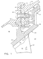
- Figure 1 illustrates a fragmentary cross-section of a portion of a gas turbine engine.
- the particular components illustrated are for example purposes only, the present invention being equally applicable to other components of similar configuration.
- Figure 1 illustrates a portion of the forward end of a low pressure turbine casing 12, which is a generally annular structure surrounding the longitudinal axis (not shown) of the engine.
- An annular turbine center frame 14 abuts the casing 12 and is secured thereto by fastening means 16.
- the casing 12 and the turbine center frame 14 each have a generally radially extending joint face, labeled 13 and 15 respectively in Figure 1.
- the casing 12 has an annular flange 56 disposed at a radially inner portion thereof.
- the fastening means 16 takes the form of a threaded nut 18 and bolt 20.
- Any known type of fastening means capable of securing the two components together could be used, for example a rivet (not shown) could be substituted for the nut 18 and bolt 20, or alternatively, one of the casing 12 or the frame 14 could have an internally threaded hole into which a bolt 20 is installed.
- a generally annular turbine nozzle 22 is suspended from the turbine center frame 14 and has an arcuate nozzle band 54 with a surface 23 which forms a portion of the boundary of a hot gas flowpath 27.
- a hollow cooled nozzle airfoil 50 (shown in partial section in Figure 1) extends radially inward from the nozzle band 54.
- a generally annular turbine shroud 24 is disposed radially inwardly of the casing 12 and has a surface 25 which forms a portion of the boundary of the hot gas flowpath 27.
- An annular cavity 28 is defined in the space between the casing 12 and the turbine shroud 24, and annular cavity 29 is defined in the space between the turbine center frame 14 and the turbine nozzle 22.
- the airfoil 50 has an interior cavity 52 which receives a flow of cooling air from the cavity 29, for example through inlet holes (not shown). After cooling the interior of the airfoil 50, the cooing air exits the airfoil 50 through an exit hole 26.
- a circumferential gap 58 exists between the turbine nozzle 22 and the turbine shroud 24.
- An annular discourager seal 30 is disposed in the joint between the turbine center frame 14 and the casing 12.
- the discourager seal 30 is a generally circular ring which has a generally L-shaped cross-section.
- the discourager seal 30 has a circumferential flange which defines a radially extending leg 32 and another circumferential flange which defines an axially extending leg 34.
- the axial leg 34 of the seal 30 has an annular array of corrugations 38 formed therein.
- the corrugations 38 comprise alternate undulations 40 and 42 which are concave and convex respectively, relative to a radially outward direction.
- the corrugations 38 give the axial leg 34 compliance in a circumferential direction so that it may shrink and expand during temperature variations without buckling or cracking.
- the number and dimensions of the corrugations 38 may be varied to suit a particular application.
- the radial leg 32 has a plurality of holes 36 formed therethrough which serve to admit fastening means 16 when the radial leg 32 is disposed between joint faces 13 and 15. Additional holes 37 may be formed in the radial leg which include a countersink (see Figure 3) to as to accept the head of a fastener (not shown).
- the discourager seal 30 may be secured to threaded holes (not shown) in the turbine center frame 14 using fasteners placed through the countersunk holes 37. This allows the discourager seal 30 to be attached to the turbine center frame 14 without installing the turbine casing 12, and thus to serve as a retainer to keep the turbine nozzle segments 22 in place during assembly of the engine.
- the radial leg 32 may also include one or more slots 39, which may serve the purpose of admitting and metering a flow of cooling air through the radial leg 32 from cavity 29 through a passage in the turbine center frame 14 (not shown) to a passage in the turbine casing 12 (also not shown) and subsequently to the cavity 28.
- the slots 39 are elongated in a radial direction.
- the discourager seal 30 is manufactured by a known method and may be made from any material capable of withstanding the operating temperatures in the engine, for example a nickel- or cobalt-based alloy.
- One suitable material is a high-temperature cobalt alloy such as that identified by SAE specification AMS 5608.
- combustion gases flow through the hot gas flowpath 27 generally in the direction of the arrow labeled A ( Figure 1).
- a separate flow of cooling air is provided to cavity 29.
- the cooling air flows into the interior cavity 52 of the airfoil 50, picking up heat therein, and subsequently exits the airfoil 50 through the exit hole 26, as shown by the arrow labeled B.
- This spent cooling air flows radially outward through the exit hole 26. Left unchecked, this flow tends to overheat the flange 56 of the casing 12.
- the axial leg 34 of the discourager seal 30 provides an impediment to the flow from the exit hole 26, which tends to turn the spent cooling flow radially inward away from the flange 56, and direct it through the gap 58 and back into the flowpath 27.
- the corrugations 38 formed in the axial leg 34 of the discourager seal 30 of the present invention make the seal 30 very compliant in the circumferential direction. In operation, when the temperature of the axial leg 34 is much higher than that of the remainder of the seal 30, the corrugations 38 allow differential circumferential growth of the axial and radial legs of the seal 30 while maintaining low stress levels. The seal 30 is therefore free of the destructive thermal stresses of prior art designs and will be more durable in service.
- a seal for a gas turbine engine comprising an annular ring with an L-shaped cross-section having a radially extending leg and an axially extending leg.
- a plurality of corrugations are formed in the axial leg so as to make it compliant in the circumferential direction.
Landscapes
- Engineering & Computer Science (AREA)
- General Engineering & Computer Science (AREA)
- Mechanical Engineering (AREA)
- Gasket Seals (AREA)
- Turbine Rotor Nozzle Sealing (AREA)
Abstract
Description
- This invention relates generally to gas turbine engines and more particularly to stationary seals used in gas turbine engines.
- A gas turbine engine includes a compressor that provides pressurized air to a combustor wherein the air is mixed with fuel and ignited for generating hot combustion gases. These gases flow downstream to one or more turbines that extract energy therefrom to power the compressor and provide useful work such as powering an aircraft in flight. In a turbofan engine, which typically includes a fan placed at the front of the core engine, a high pressure turbine powers the compressor of the core engine. A low pressure turbine is disposed downstream from the high pressure turbine for powering the fan.
- An engine has a primary flowpath through the compressor, combustor, and turbine for hot combustion gases. There are also secondary flowpaths for various purposes, for example cooling flows, sump pressurization, etc., as well as various enclosed cavities which are isolated from the primary flowpath of the engine.
- It is common in the prior art to require discourager seals at various locations within the hot section of a gas turbine engine and adjacent to the primary flowpath for purposes of preventing hot gas ingestion into the engine's cavities. A typical discourager seal has an L-shaped cross-section including a radial leg or flange for attachment of the seal, for example in a bolted joint between two stationary structures, and an axially extending leg adjacent to the flowpath. The nature of the discourager seal function is such that the axial leg near the flowpath will operate at very high temperature, while the flanged portion is typically much cooler. The resulting thermal stresses in the axial leg, which is typically a simple cylindrical flange, can be destructive and lead to buckling or low-cycle fatigue cracking of the axial leg of the seal.
- Accordingly, there is a need for a discourager seal having improved durability when exposed to high temperatures.
- The above-mentioned need is met by the present invention, which provides a seal for a gas turbine engine, comprising an annular ring with an L-shaped cross-section having a radially extending leg and an axially extending leg. A plurality of corrugations are formed in the axial leg so as to make it compliant in the circumferential direction.
- The invention will now be described in greater detail, by way of example, with reference to the drawings, in which:-
- Figure 1 is a fragmentary cross-sectional view of a portion of a gas turbine engine.
- Figure 2 is an aft-looking-forward view of a portion of a discourager seal constructed in accordance with the present invention.
- Figure 3 is a cross-sectional view taken along lines 3-3 of Figure 2.
- Figure 4 is a cross-sectional view taken along lines 4-4 of Figure 3.
-
- Referring to the drawings wherein identical reference numerals denote the same elements throughout the various views, Figure 1 illustrates a fragmentary cross-section of a portion of a gas turbine engine. The particular components illustrated are for example purposes only, the present invention being equally applicable to other components of similar configuration. Figure 1 illustrates a portion of the forward end of a low
pressure turbine casing 12, which is a generally annular structure surrounding the longitudinal axis (not shown) of the engine. An annularturbine center frame 14 abuts thecasing 12 and is secured thereto by fastening means 16. Thecasing 12 and theturbine center frame 14 each have a generally radially extending joint face, labeled 13 and 15 respectively in Figure 1. Thecasing 12 has anannular flange 56 disposed at a radially inner portion thereof. In the illustrated example the fastening means 16 takes the form of a threadednut 18 andbolt 20. Any known type of fastening means capable of securing the two components together could be used, for example a rivet (not shown) could be substituted for thenut 18 andbolt 20, or alternatively, one of thecasing 12 or theframe 14 could have an internally threaded hole into which abolt 20 is installed. - A generally
annular turbine nozzle 22 is suspended from theturbine center frame 14 and has anarcuate nozzle band 54 with asurface 23 which forms a portion of the boundary of ahot gas flowpath 27. A hollow cooled nozzle airfoil 50 (shown in partial section in Figure 1) extends radially inward from thenozzle band 54. A generallyannular turbine shroud 24 is disposed radially inwardly of thecasing 12 and has asurface 25 which forms a portion of the boundary of thehot gas flowpath 27. Anannular cavity 28 is defined in the space between thecasing 12 and theturbine shroud 24, andannular cavity 29 is defined in the space between theturbine center frame 14 and theturbine nozzle 22. Theairfoil 50 has aninterior cavity 52 which receives a flow of cooling air from thecavity 29, for example through inlet holes (not shown). After cooling the interior of theairfoil 50, the cooing air exits theairfoil 50 through anexit hole 26. Acircumferential gap 58 exists between theturbine nozzle 22 and theturbine shroud 24. Anannular discourager seal 30 is disposed in the joint between theturbine center frame 14 and thecasing 12. Thediscourager seal 30 is a generally circular ring which has a generally L-shaped cross-section. Thediscourager seal 30 has a circumferential flange which defines a radially extendingleg 32 and another circumferential flange which defines an axially extendingleg 34. - Referring now to Figures, 2, 3 and 4, the
discourager seal 30 is shown in more detail. Theaxial leg 34 of theseal 30 has an annular array ofcorrugations 38 formed therein. Thecorrugations 38 comprisealternate undulations corrugations 38 give theaxial leg 34 compliance in a circumferential direction so that it may shrink and expand during temperature variations without buckling or cracking. The number and dimensions of thecorrugations 38 may be varied to suit a particular application. - The
radial leg 32 has a plurality ofholes 36 formed therethrough which serve to admit fastening means 16 when theradial leg 32 is disposed betweenjoint faces Additional holes 37 may be formed in the radial leg which include a countersink (see Figure 3) to as to accept the head of a fastener (not shown). Thediscourager seal 30 may be secured to threaded holes (not shown) in theturbine center frame 14 using fasteners placed through thecountersunk holes 37. This allows thediscourager seal 30 to be attached to theturbine center frame 14 without installing theturbine casing 12, and thus to serve as a retainer to keep theturbine nozzle segments 22 in place during assembly of the engine. Theradial leg 32 may also include one ormore slots 39, which may serve the purpose of admitting and metering a flow of cooling air through theradial leg 32 fromcavity 29 through a passage in the turbine center frame 14 (not shown) to a passage in the turbine casing 12 (also not shown) and subsequently to thecavity 28. In the illustrated example theslots 39 are elongated in a radial direction. Thediscourager seal 30 is manufactured by a known method and may be made from any material capable of withstanding the operating temperatures in the engine, for example a nickel- or cobalt-based alloy. One suitable material is a high-temperature cobalt alloy such as that identified by SAE specification AMS 5608. - In operation, combustion gases flow through the
hot gas flowpath 27 generally in the direction of the arrow labeled A (Figure 1). A separate flow of cooling air is provided tocavity 29. The cooling air flows into theinterior cavity 52 of theairfoil 50, picking up heat therein, and subsequently exits theairfoil 50 through theexit hole 26, as shown by the arrow labeled B. This spent cooling air flows radially outward through theexit hole 26. Left unchecked, this flow tends to overheat theflange 56 of thecasing 12. Theaxial leg 34 of thediscourager seal 30 provides an impediment to the flow from theexit hole 26, which tends to turn the spent cooling flow radially inward away from theflange 56, and direct it through thegap 58 and back into theflowpath 27. Thecorrugations 38 formed in theaxial leg 34 of thediscourager seal 30 of the present invention make theseal 30 very compliant in the circumferential direction. In operation, when the temperature of theaxial leg 34 is much higher than that of the remainder of theseal 30, thecorrugations 38 allow differential circumferential growth of the axial and radial legs of theseal 30 while maintaining low stress levels. Theseal 30 is therefore free of the destructive thermal stresses of prior art designs and will be more durable in service. - The foregoing has described a seal for a gas turbine engine, comprising an annular ring with an L-shaped cross-section having a radially extending leg and an axially extending leg. A plurality of corrugations are formed in the axial leg so as to make it compliant in the circumferential direction.
- For the sake of good order, various aspects of the invention are set out in the following clauses:-
- 1. A seal (30) for a gas turbine engine, comprising:
- a circumferentially extending ring, said ring having a radially extending leg (32) and an axially extending leg,
- said axially extending leg (34) comprising a plurality of corrugations (38).
- 2. The seal (30) of clause 1, wherein said corrugations (38) comprise an annular array of alternating convex and concave undulations formed in said axially extending leg.
- 3. The seal (30) of clause 1, wherein said seal (30) is formed from a metal alloy.
- 4. The seal (30) of clause 1 further comprising a plurality of holes (36) formed through said radially extending leg (32).
- 5. The seal (30) of clause 1 further comprising a plurality of elongated slots (39) formed through said radially extending leg (32).
- 6. The seal (30) of clause 1 further comprising a plurality of countersunk holes (37) formed through said radially extending leg (32).
- 7. A joint assembly for a gas turbine engine, comprising:
- a first generally annular member having a first radially extending joint face;
- a second generally annular member having a second radially
extending joint face:
- an annular seal (30) disposed between said first and second annular members, said seal (30) comprising: a radially extending leg (32) connected to an axially extending leg (34), wherein said radially extending leg (32) is disposed between said first joint face and said second joint face, wherein said axially extending leg (34) is corrugated in a circumferential direction.
- 8. The joint assembly of clause 7, wherein said seal (30) is formed from a metal alloy.
- 9. The joint assembly of clause 7 further comprising a plurality of holes (36) formed through said radially extending leg (32).
- 10. The joint assembly of clause 7 further comprising a plurality of elongated slots (39) formed through said radially extending leg (32).
- 11. The joint assembly of clause 7 further comprising a plurality of countersunk holes (37) formed through said radially extending leg (32) of said discourager seal (30).
- 12. A joint assembly for a gas turbine engine, comprising:
- a generally annular turbine frame (14) having a first radially extending joint face;
- a generally annular turbine casing (12) disposed axially rearward of said turbine frame (14) and having a second radially extending joint face;
- an annular turbine nozzle (22) disposed radially inward of said turbine frame (14), said turbine nozzle (22) comprising a hollow airfoil and an arcuate band (54), said band (54) having an exit hole (26) formed therein;
- an annular turbine shroud (24) having a surface defining a gas flowpath, said turbine shroud (24) disposed radially inward of said turbine casing (12), such that an annular cavity is defined between said turbine casing (12) and said turbine shroud (24), and such that a circumferentially extending gap (58) is defined between said turbine shroud (24) and said turbine nozzle (22), said gap (58) being in fluid communication with said flowpath and said annular cavity; and
- an annular discourager seal (30) disposed between said turbine frame (14) and said turbine casing (12), said discourager seal (30) comprising a radially extending leg (32) connected to an axially extending leg (34), wherein said radially extending leg (32) is disposed between said first joint face and said second joint face, and said axially extending leg (34) is disposed so as to redirect a fluid flow from said exit hole (26), and wherein said axially extending leg (34) comprises an annular array of corrugations (38).
- 13. The joint assembly of
clause 12, wherein said discourager seal (30) is formed from a metal alloy. - 14. The joint assembly of
clause 12 further comprising a plurality of holes (36) formed through said radially extending leg (32) of said discourager seal (30). - 15. The joint assembly of
clause 12 further comprising a plurality of elongated slots (39) formed through said radially extending leg (32) of said discourager seal (30). - 16. The joint assembly of
clause 12 further comprising a plurality of countersunk holes (37) formed through said radially extending leg (32) of said discourager seal (30). -
Claims (10)
- A seal (30) for a gas turbine engine, comprising:a circumferentially extending ring, said ring having a radially extending leg (32) and an axially extending leg,said axially extending leg (34) comprising a plurality of corrugations (38).
- The seal (30) of claim 1, wherein said corrugations (38) comprise an annular array of alternating convex and concave undulations formed in said axially extending leg.
- The seal (30) of claim 1 or 2, wherein said seal (30) is formed from a metal alloy.
- The seal (30) of claim 1, 2 or 3 further comprising a plurality of holes (36) formed through said radially extending leg (32).
- A joint assembly for a gas turbine engine, comprising:a first generally annular member having a first radially extending joint face;a second generally annular member having a second radially extending joint face:an annular seal (30) disposed between said first and second annular members, said seal (30) comprising: a radially extending leg (32) connected to an axially extending leg (34), wherein said radially extending leg (32) is disposed between said first joint face and said second joint face, wherein said axially extending leg (34) is corrugated in a circumferential direction.
- The joint assembly of claim 5, wherein said seal (30) is formed from a metal alloy.
- The joint assembly of claim 5 or 6 further comprising a plurality of holes (36) formed through said radially extending leg (32).
- A joint assembly for a gas turbine engine, comprising:a generally annular turbine frame (14) having a first radially extending joint face;a generally annular turbine casing (12) disposed axially rearward of said turbine frame (14) and having a second radially extending joint face;an annular turbine nozzle (22) disposed radially inward of said turbine frame (14), said turbine nozzle (22) comprising a hollow airfoil and an arcuate band (54), said band (54) having an exit hole (26) formed therein;an annular turbine shroud (24) having a surface defining a gas flowpath, said turbine shroud (24) disposed radially inward of said turbine casing (12), such that an annular cavity is defined between said turbine casing (12) and said turbine shroud (24), and such that a circumferentially extending gap (58) is defined between said turbine shroud (24) and said turbine nozzle (22), said gap (58) being in fluid communication with said flowpath and said annular cavity; andan annular discourager seal (30) disposed between said turbine frame (14) and said turbine casing (12), said discourager seal (30) comprising a radially extending leg (32) connected to an axially extending leg (34), wherein said radially extending leg (32) is disposed between said first joint face and said second joint face, and said axially extending leg (34) is disposed so as to redirect a fluid flow from said exit hole (26), and wherein said axially extending leg (34) comprises an annular array of corrugations (38).
- The joint assembly of claim 8, wherein said discourager seal (30) is formed from a metal alloy.
- The joint assembly of claim 8 or 9 further comprising a plurality of holes (36) formed through said radially extending leg (32) of said discourager seal (30).
Applications Claiming Priority (2)
| Application Number | Priority Date | Filing Date | Title |
|---|---|---|---|
| US996268 | 1992-12-24 | ||
| US09/996,268 US6612809B2 (en) | 2001-11-28 | 2001-11-28 | Thermally compliant discourager seal |
Publications (2)
| Publication Number | Publication Date |
|---|---|
| EP1316677A1 true EP1316677A1 (en) | 2003-06-04 |
| EP1316677B1 EP1316677B1 (en) | 2005-05-11 |
Family
ID=25542701
Family Applications (1)
| Application Number | Title | Priority Date | Filing Date |
|---|---|---|---|
| EP02258140A Expired - Lifetime EP1316677B1 (en) | 2001-11-28 | 2002-11-27 | Thermally compliant discourager seal |
Country Status (5)
| Country | Link |
|---|---|
| US (1) | US6612809B2 (en) |
| EP (1) | EP1316677B1 (en) |
| JP (1) | JP4216052B2 (en) |
| CN (1) | CN1318736C (en) |
| DE (1) | DE60204105T2 (en) |
Cited By (3)
| Publication number | Priority date | Publication date | Assignee | Title |
|---|---|---|---|---|
| EP3085901A1 (en) * | 2015-04-22 | 2016-10-26 | United Technologies Corporation | Seal |
| US11021962B2 (en) * | 2018-08-22 | 2021-06-01 | Raytheon Technologies Corporation | Turbulent air reducer for a gas turbine engine |
| US11053474B2 (en) | 2013-03-13 | 2021-07-06 | Novozymes A/S | Lactobacillus strains and the uses thereof |
Families Citing this family (35)
| Publication number | Priority date | Publication date | Assignee | Title |
|---|---|---|---|---|
| US7562880B2 (en) * | 2004-02-09 | 2009-07-21 | Siemens Energy, Inc. | Seal usable between thermally movable components |
| FR2868125B1 (en) * | 2004-03-26 | 2006-07-21 | Snecma Moteurs Sa | TURBOMACHINE COMPRISING TWO SUBASSEMBLIES ASSEMBLED WITH AXIAL CONSTRAINTS |
| FR2899281B1 (en) * | 2006-03-30 | 2012-08-10 | Snecma | DEVICE FOR COOLING A TURBINE HOUSING OF A TURBOMACHINE |
| US20080025838A1 (en) * | 2006-07-25 | 2008-01-31 | Siemens Power Generation, Inc. | Ring seal for a turbine engine |
| CA2671507A1 (en) | 2006-12-19 | 2008-06-26 | Basf Se | Uses and methods for preventing and/or treating caries caused by mutans streptococci |
| US20090096174A1 (en) * | 2007-02-28 | 2009-04-16 | United Technologies Corporation | Blade outer air seal for a gas turbine engine |
| US8439639B2 (en) * | 2008-02-24 | 2013-05-14 | United Technologies Corporation | Filter system for blade outer air seal |
| US8312729B2 (en) * | 2009-09-21 | 2012-11-20 | Honeywell International Inc. | Flow discouraging systems and gas turbine engines |
| US9482107B2 (en) * | 2009-09-28 | 2016-11-01 | Siemens Aktiengesellschaft | Gas turbine nozzle arrangement and gas turbine |
| US8500392B2 (en) * | 2009-10-01 | 2013-08-06 | Pratt & Whitney Canada Corp. | Sealing for vane segments |
| US8690527B2 (en) | 2010-06-30 | 2014-04-08 | Honeywell International Inc. | Flow discouraging systems and gas turbine engines |
| US20120263580A1 (en) * | 2011-04-14 | 2012-10-18 | General Electric Company | Flexible seal for turbine engine |
| DE102012201050B4 (en) * | 2012-01-25 | 2017-11-30 | MTU Aero Engines AG | Sealing arrangement, method and turbomachine |
| US9309775B2 (en) | 2012-05-21 | 2016-04-12 | United Technologies Corporation | Rotational debris discourager for gas turbine engine bearing |
| US9541006B2 (en) | 2012-12-29 | 2017-01-10 | United Technologies Corporation | Inter-module flow discourager |
| JP6271582B2 (en) | 2012-12-29 | 2018-01-31 | ユナイテッド テクノロジーズ コーポレイションUnited Technologies Corporation | Gas turbine seal assembly and seal support |
| WO2014105800A1 (en) * | 2012-12-29 | 2014-07-03 | United Technologies Corporation | Gas turbine seal assembly and seal support |
| US9879558B2 (en) | 2013-02-07 | 2018-01-30 | United Technologies Corporation | Low leakage multi-directional interface for a gas turbine engine |
| EP3055538B1 (en) * | 2013-10-09 | 2024-02-28 | RTX Corporation | Spacer for power turbine inlet heat shield |
| WO2015112238A1 (en) * | 2014-01-24 | 2015-07-30 | United Technologies Corporation | Toggle seal for a rim seal |
| CN104389645A (en) * | 2014-11-15 | 2015-03-04 | 哈尔滨广瀚燃气轮机有限公司 | Sealing structure for novel turbine motor high-temperature thermal expansion compensation stator |
| CN104791103B (en) * | 2015-03-27 | 2018-09-14 | 北京华清燃气轮机与煤气化联合循环工程技术有限公司 | Sealing structure between quiet-quiet chamber of gas turbine |
| ES2861200T3 (en) * | 2015-12-15 | 2021-10-06 | MTU Aero Engines AG | Turbomachinery Component Connection |
| US9708922B1 (en) | 2016-05-23 | 2017-07-18 | United Technologies Corporation | Seal ring for gas turbine engines |
| US10202863B2 (en) | 2016-05-23 | 2019-02-12 | United Technologies Corporation | Seal ring for gas turbine engines |
| US20180045218A1 (en) * | 2016-08-11 | 2018-02-15 | United Technologies Corporation | Shim for gas turbine engine |
| US10359117B2 (en) * | 2017-03-06 | 2019-07-23 | General Electric Company | Aspirating face seal with non-coiled retraction springs |
| US10570760B2 (en) * | 2017-04-13 | 2020-02-25 | General Electric Company | Turbine nozzle with CMC aft band |
| US10711629B2 (en) | 2017-09-20 | 2020-07-14 | Generl Electric Company | Method of clearance control for an interdigitated turbine engine |
| US10458267B2 (en) | 2017-09-20 | 2019-10-29 | General Electric Company | Seal assembly for counter rotating turbine assembly |
| CN109139136B (en) * | 2018-09-25 | 2024-03-22 | 中国船舶重工集团公司第七0三研究所 | Steam turbine reversing cylinder steam inlet pipe fixing structure |
| US11428124B2 (en) * | 2018-11-21 | 2022-08-30 | Raytheon Technologies Corporation | Flange stress-reduction features |
| US11125093B2 (en) * | 2019-10-22 | 2021-09-21 | Raytheon Technologies Corporation | Vane with L-shaped seal |
| US11428160B2 (en) | 2020-12-31 | 2022-08-30 | General Electric Company | Gas turbine engine with interdigitated turbine and gear assembly |
| US20240151152A1 (en) * | 2022-11-08 | 2024-05-09 | Raytheon Technologies Corporation | Seal for gas turbine engine |
Citations (5)
| Publication number | Priority date | Publication date | Assignee | Title |
|---|---|---|---|---|
| FR2596115A1 (en) * | 1986-03-21 | 1987-09-25 | Rolls Royce | Improvement to retention means |
| EP0482791A1 (en) * | 1990-10-22 | 1992-04-29 | General Electric Company | Windage shield |
| EP0513956A1 (en) * | 1991-05-13 | 1992-11-19 | General Electric Company | Boltless turbine nozzle/stationary seal mounting |
| US5259725A (en) * | 1992-10-19 | 1993-11-09 | General Electric Company | Gas turbine engine and method of assembling same |
| DE19912135A1 (en) * | 1998-05-20 | 1999-12-09 | Freudenberg Carl Fa | Shaft seal incorporates temperature sensor projecting into fluid retained by seal |
Family Cites Families (21)
| Publication number | Priority date | Publication date | Assignee | Title |
|---|---|---|---|---|
| US3720419A (en) * | 1971-01-21 | 1973-03-13 | Westinghouse Electric Corp | Fabricated labyrinth seal structure |
| CA1063139A (en) | 1976-03-09 | 1979-09-25 | Westinghouse Electric Corporation | Variable radius springback wavy seal |
| US4309145A (en) * | 1978-10-30 | 1982-01-05 | General Electric Company | Cooling air seal |
| US4285633A (en) * | 1979-10-26 | 1981-08-25 | The United States Of America As Represented By The Secretary Of The Air Force | Broad spectrum vibration damper assembly fixed stator vanes of axial flow compressor |
| DE2946324A1 (en) | 1979-11-16 | 1981-06-04 | MTU Motoren- und Turbinen-Union München GmbH, 8000 München | GASKET SEALING DEVICE FOR A JET BEAM DEFLECTING DEVICE |
| US4304522A (en) * | 1980-01-15 | 1981-12-08 | Pratt & Whitney Aircraft Of Canada Limited | Turbine bearing support |
| US4548427A (en) * | 1981-08-24 | 1985-10-22 | Umc Industries, Inc. | Strain accommodating fluid conduit assembly and fitting therefor |
| US4662658A (en) * | 1984-06-04 | 1987-05-05 | General Electric Company | Seal |
| US4883405A (en) * | 1987-11-13 | 1989-11-28 | The United States Of America As Represented By The Secretary Of The Air Force | Turbine nozzle mounting arrangement |
| US4979755A (en) * | 1988-02-18 | 1990-12-25 | Westinghouse Electric Corp. | Flow dams in labyrinth seals to improve rotor stability |
| US5096376A (en) | 1990-08-29 | 1992-03-17 | General Electric Company | Low windage corrugated seal facing strip |
| US5361577A (en) * | 1991-07-15 | 1994-11-08 | General Electric Company | Spring loaded cross-fire tube |
| US5218816A (en) | 1992-01-28 | 1993-06-15 | General Electric Company | Seal exit flow discourager |
| US5316405A (en) | 1992-10-29 | 1994-05-31 | Josif Atanasoski | Cyclone seal expansion joint |
| US5749218A (en) * | 1993-12-17 | 1998-05-12 | General Electric Co. | Wear reduction kit for gas turbine combustors |
| US5513955A (en) * | 1994-12-14 | 1996-05-07 | United Technologies Corporation | Turbine engine rotor blade platform seal |
| US5709530A (en) * | 1996-09-04 | 1998-01-20 | United Technologies Corporation | Gas turbine vane seal |
| US5868398A (en) * | 1997-05-20 | 1999-02-09 | United Technologies Corporation | Gas turbine stator vane seal |
| US6076835A (en) * | 1997-05-21 | 2000-06-20 | Allison Advanced Development Company | Interstage van seal apparatus |
| US5971703A (en) * | 1997-12-05 | 1999-10-26 | Pratt & Whitney Canada Inc. | Seal assembly for a gas turbine engine |
| JP3643692B2 (en) * | 1998-03-02 | 2005-04-27 | 三菱重工業株式会社 | Rotating machine sealing device |
-
2001
- 2001-11-28 US US09/996,268 patent/US6612809B2/en not_active Expired - Lifetime
-
2002
- 2002-11-27 DE DE60204105T patent/DE60204105T2/en not_active Expired - Lifetime
- 2002-11-27 EP EP02258140A patent/EP1316677B1/en not_active Expired - Lifetime
- 2002-11-27 JP JP2002343164A patent/JP4216052B2/en not_active Expired - Fee Related
- 2002-11-28 CN CNB021527784A patent/CN1318736C/en not_active Expired - Fee Related
Patent Citations (5)
| Publication number | Priority date | Publication date | Assignee | Title |
|---|---|---|---|---|
| FR2596115A1 (en) * | 1986-03-21 | 1987-09-25 | Rolls Royce | Improvement to retention means |
| EP0482791A1 (en) * | 1990-10-22 | 1992-04-29 | General Electric Company | Windage shield |
| EP0513956A1 (en) * | 1991-05-13 | 1992-11-19 | General Electric Company | Boltless turbine nozzle/stationary seal mounting |
| US5259725A (en) * | 1992-10-19 | 1993-11-09 | General Electric Company | Gas turbine engine and method of assembling same |
| DE19912135A1 (en) * | 1998-05-20 | 1999-12-09 | Freudenberg Carl Fa | Shaft seal incorporates temperature sensor projecting into fluid retained by seal |
Cited By (4)
| Publication number | Priority date | Publication date | Assignee | Title |
|---|---|---|---|---|
| US11053474B2 (en) | 2013-03-13 | 2021-07-06 | Novozymes A/S | Lactobacillus strains and the uses thereof |
| EP3085901A1 (en) * | 2015-04-22 | 2016-10-26 | United Technologies Corporation | Seal |
| US10041366B2 (en) | 2015-04-22 | 2018-08-07 | United Technologies Corporation | Seal |
| US11021962B2 (en) * | 2018-08-22 | 2021-06-01 | Raytheon Technologies Corporation | Turbulent air reducer for a gas turbine engine |
Also Published As
| Publication number | Publication date |
|---|---|
| DE60204105T2 (en) | 2006-01-19 |
| DE60204105D1 (en) | 2005-06-16 |
| EP1316677B1 (en) | 2005-05-11 |
| CN1421593A (en) | 2003-06-04 |
| JP4216052B2 (en) | 2009-01-28 |
| US20030099542A1 (en) | 2003-05-29 |
| US6612809B2 (en) | 2003-09-02 |
| CN1318736C (en) | 2007-05-30 |
| JP2003201807A (en) | 2003-07-18 |
Similar Documents
| Publication | Publication Date | Title |
|---|---|---|
| EP1316677B1 (en) | Thermally compliant discourager seal | |
| EP1491823B1 (en) | Rabbet mounted gas turbine combustor | |
| US9879556B2 (en) | Cooled finger seal | |
| JP5503662B2 (en) | Saw wall type turbine nozzle | |
| US9810097B2 (en) | Corrugated mid-turbine frame thermal radiation shield | |
| US11008888B2 (en) | Turbine vane assembly with ceramic matrix composite components | |
| US10494946B2 (en) | Method of making a turbine shroud | |
| US20090226300A1 (en) | Passage obstruction for improved inlet coolant filling | |
| EP3315866A1 (en) | Combustor assembly with mounted auxiliary component | |
| EP2679775A1 (en) | A transition duct for a gas turbine | |
| EP3232018B1 (en) | Heat shield with axial retention lock | |
| US10718450B2 (en) | Flange joint assembly for use in a gas turbine engine | |
| US10928067B2 (en) | Double skin combustor | |
| US10816204B2 (en) | Heat shield with axial retention lock | |
| US10273821B2 (en) | Advanced stationary sealing cooled cross-section for axial retention of ceramic matrix composite shrouds | |
| EP1217231B1 (en) | Bolted joint for rotor disks and method of reducing thermal gradients therein | |
| EP3312394B1 (en) | Engine cases and associated flange | |
| US20180258790A1 (en) | Turbine housing assembly | |
| CN112539087B (en) | Turbine Snap in Spring Seal |
Legal Events
| Date | Code | Title | Description |
|---|---|---|---|
| PUAI | Public reference made under article 153(3) epc to a published international application that has entered the european phase |
Free format text: ORIGINAL CODE: 0009012 |
|
| AK | Designated contracting states |
Designated state(s): AT BE BG CH CY CZ DE DK EE ES FI FR GB GR IE IT LI LU MC NL PT SE SK TR |
|
| AX | Request for extension of the european patent |
Extension state: AL LT LV MK RO SI |
|
| 17P | Request for examination filed |
Effective date: 20031204 |
|
| AKX | Designation fees paid |
Designated state(s): DE FR GB |
|
| 17Q | First examination report despatched |
Effective date: 20040304 |
|
| GRAP | Despatch of communication of intention to grant a patent |
Free format text: ORIGINAL CODE: EPIDOSNIGR1 |
|
| GRAS | Grant fee paid |
Free format text: ORIGINAL CODE: EPIDOSNIGR3 |
|
| GRAA | (expected) grant |
Free format text: ORIGINAL CODE: 0009210 |
|
| AK | Designated contracting states |
Kind code of ref document: B1 Designated state(s): DE FR GB |
|
| REG | Reference to a national code |
Ref country code: GB Ref legal event code: FG4D |
|
| REG | Reference to a national code |
Ref country code: IE Ref legal event code: FG4D |
|
| REF | Corresponds to: |
Ref document number: 60204105 Country of ref document: DE Date of ref document: 20050616 Kind code of ref document: P |
|
| ET | Fr: translation filed | ||
| PLBE | No opposition filed within time limit |
Free format text: ORIGINAL CODE: 0009261 |
|
| STAA | Information on the status of an ep patent application or granted ep patent |
Free format text: STATUS: NO OPPOSITION FILED WITHIN TIME LIMIT |
|
| 26N | No opposition filed |
Effective date: 20060214 |
|
| REG | Reference to a national code |
Ref country code: FR Ref legal event code: PLFP Year of fee payment: 14 |
|
| PGFP | Annual fee paid to national office [announced via postgrant information from national office to epo] |
Ref country code: GB Payment date: 20151127 Year of fee payment: 14 Ref country code: DE Payment date: 20151127 Year of fee payment: 14 |
|
| PGFP | Annual fee paid to national office [announced via postgrant information from national office to epo] |
Ref country code: FR Payment date: 20151117 Year of fee payment: 14 |
|
| REG | Reference to a national code |
Ref country code: DE Ref legal event code: R119 Ref document number: 60204105 Country of ref document: DE |
|
| GBPC | Gb: european patent ceased through non-payment of renewal fee |
Effective date: 20161127 |
|
| REG | Reference to a national code |
Ref country code: FR Ref legal event code: ST Effective date: 20170731 |
|
| PG25 | Lapsed in a contracting state [announced via postgrant information from national office to epo] |
Ref country code: FR Free format text: LAPSE BECAUSE OF NON-PAYMENT OF DUE FEES Effective date: 20161130 |
|
| PG25 | Lapsed in a contracting state [announced via postgrant information from national office to epo] |
Ref country code: DE Free format text: LAPSE BECAUSE OF NON-PAYMENT OF DUE FEES Effective date: 20170601 Ref country code: GB Free format text: LAPSE BECAUSE OF NON-PAYMENT OF DUE FEES Effective date: 20161127 |