EP1316638A1 - Arrangement for mounting a screen - Google Patents
Arrangement for mounting a screen Download PDFInfo
- Publication number
- EP1316638A1 EP1316638A1 EP02102531A EP02102531A EP1316638A1 EP 1316638 A1 EP1316638 A1 EP 1316638A1 EP 02102531 A EP02102531 A EP 02102531A EP 02102531 A EP02102531 A EP 02102531A EP 1316638 A1 EP1316638 A1 EP 1316638A1
- Authority
- EP
- European Patent Office
- Prior art keywords
- screen
- reactor
- arrangement
- digester
- screens
- Prior art date
- Legal status (The legal status is an assumption and is not a legal conclusion. Google has not performed a legal analysis and makes no representation as to the accuracy of the status listed.)
- Granted
Links
- 239000007788 liquid Substances 0.000 claims abstract description 9
- 229920001131 Pulp (paper) Polymers 0.000 claims abstract description 6
- 239000002184 metal Substances 0.000 description 8
- 238000010276 construction Methods 0.000 description 6
- 238000010411 cooking Methods 0.000 description 6
- 238000004519 manufacturing process Methods 0.000 description 6
- 238000001914 filtration Methods 0.000 description 4
- 238000000034 method Methods 0.000 description 3
- 239000007787 solid Substances 0.000 description 2
- 238000003466 welding Methods 0.000 description 2
- 238000005452 bending Methods 0.000 description 1
- 238000005520 cutting process Methods 0.000 description 1
- 230000001419 dependent effect Effects 0.000 description 1
- 230000008021 deposition Effects 0.000 description 1
- 230000000694 effects Effects 0.000 description 1
- 238000012986 modification Methods 0.000 description 1
- 230000004048 modification Effects 0.000 description 1
- 238000005406 washing Methods 0.000 description 1
- 230000003313 weakening effect Effects 0.000 description 1
Images

Classifications
-
- D—TEXTILES; PAPER
- D21—PAPER-MAKING; PRODUCTION OF CELLULOSE
- D21C—PRODUCTION OF CELLULOSE BY REMOVING NON-CELLULOSE SUBSTANCES FROM CELLULOSE-CONTAINING MATERIALS; REGENERATION OF PULPING LIQUORS; APPARATUS THEREFOR
- D21C7/00—Digesters
-
- D—TEXTILES; PAPER
- D21—PAPER-MAKING; PRODUCTION OF CELLULOSE
- D21C—PRODUCTION OF CELLULOSE BY REMOVING NON-CELLULOSE SUBSTANCES FROM CELLULOSE-CONTAINING MATERIALS; REGENERATION OF PULPING LIQUORS; APPARATUS THEREFOR
- D21C7/00—Digesters
- D21C7/14—Means for circulating the lye
Definitions
- the present invention relates to an arrangement according to the preamble of claim 1.
- This type of arrangement involves particularly the arranging of a bar screen in a continuous pulp reactors, which is known as a Kamyr reactor.
- a continuous pulp reactors which is known as a Kamyr reactor.
- Such an arrangement can be utilised in reactors in use, the operation of which post-mounted new screens will improve, and in new continuous reactors.
- the purpose of a screen to be mounted is, in particular, the efficient removal of cooking and circulation liquid from a vessel of a reactor when chemical pulp or paper pulp is made with a continuous reactor.
- continuous digesters for instance comprise substantially cylindrical pressure vessels arranged in an upright position.
- Pressure vessels of continuous pulp digesters are remarkably high, and their diameter can be several metres.
- the diameter of the bottom part of a pressure vessel may be 4000 mm to 10000 mm, typically about 6000 mm.
- the diameter of the cover of such a pressure vessel is usually smaller at the top end of the digester than at its bottom end.
- the diameter of the digester does not increase conically along the entire length of the digester, but is arranged to increase at regionally defined areas by means of one or more conical sections. The exact positions of the conical sections are defined by process-specific technical grounds.
- the digester comprises screens, which are usually mounted below the above-mentioned conical sections. In such a case, the distance between the upper edge of the screen and the lower edge of the conical section is selected so as to vary from a few hundred millimetres to several metres.
- the cover of a pressure vessel of a pulp digester is usually made of metal plates, the thickness of which may vary from 20 mm to 50 mm, the width from 1000 mm to 3000 mm and the length from 4000 mm up to 6000 mm.
- metal plates are welded together so as to form cover blanks, which correspond to the circumference of the pressure vessel.
- cover blanks are bent into cylindrical pieces of the cover, which are welded together with a round joint in order to form a cover for the cylindrical pressure vessel of the digester.
- the conical sections at the cover of the pressure vessel are also made by bending a long blank into a cone and by welding the conical sections to the rest of the cover of the pressure vessel with a round joint.
- the cross-sectional profile of a finished digester often differs from the planned theoretical circular cross-section considerably and is, in fact, more like elliptical.
- the vertical joint of the pressure vessel i.e. the joint which combines the ends of the cover blank forming the pressure vessel, may be markedly discontinuous. At this vertical joint, due to welding stress, the shape usually differs from an elliptical curve and is more like angular.
- this type of screens are mounted, for instance, in the washing cycle of a continuous digester, i.e. at the lower end of a pressure vessel forming the digester, so that the region of a cone which increases the diameter of the digester of the pressure vessel is provided with a solid annular metal plate - a kind of a trailing edge - allowing a cooking flow of chips to pass untroubled from the top of the digester to the bottom of the digester where it is subjected to the influence of the screens.
- An upper back-up ring arranged substantially horizontally on the inner surface of the pressure vessel is supported underneath the cone which increases the diameter, the ring being arranged to support both the upper edge of the screens to be mounted in the pressure vessel and the annular metal plate onto the cover of the pressure vessel.
- a lower back-up ring is conventionally supported onto the inner surface of the pressure vessel substantially horizontally so that it supports the lower edge of the screens onto the cover of the pressure vessel.
- a number of vertical supports required by the screens are fixed conventionally between these upper and lower back-up rings.
- the edges of the screens are attached to a "grid" being formed by the support structures, which grid is also called a screen bed.
- the invention provides considerable advantages. By using the present system, it is much easier to mount screens in a pressure vessel than by using known solutions. Also, screens are supported much more reliably than before, whereupon the force stress directed to the screens is distributed to the cover of the pressure vessel according to the strength calculations. The present arrangement also allows screens with a larger area to be mounted in a digester, which improves the productivity of the digester.
- the present invention also increases the flow behind the screen, which makes the operation of the digester more effective and prevents the deposition in the background space of the screens.
- FIG. 1 With reference to Figure 1, particularly to its part on the righthand side, a conventionally known fixing arrangement of screens 1 of a continuous pulp digester can be described as follows.
- the figures show a pressure cover 2 of the digester, comprising a second lowest, cylindrical cover section 3, a lowest conical section 4, a lowest cover section 5 and a bottom end 6.
- the region of the conical section is provided with a solid metal ring plate 7 with a substantially corresponding diameter.
- the ring plate is thus arranged to guide a cooking flow of chips from the top of the digester to a region where it is subjected to the influence of the screen 1 serving as an extension for the ring plate.
- a substantially horizontal upper back-up ring is arranged underneath the conical section in a known manner, the ring supporting the upper edge of the screen and the lower edge of the ring plate onto the inner surface 8 of the pressure cover of the digester.
- a lower back-up ring is arranged horizontally on the inner surface of the digester to support the screen at its lower edge.
- a number of vertical supports required by the screens are arranged between these parallel support rings, whereby the support rings and the vertical supports form a grid-like screen bed. The outer edges of the screens are attached to this screen bed.
- the screens 1 comprise a number of parallel screen bars, which form a screen surface which faces towards the central axis 9 of the digester. This screen surface is subjected to force effects of chip flow moving in the digester, which force is arranged to be transmitted to the pressure cover 2 of the digester by means of support rods, i.e. round bars of specific length fixed to the transverse supports.
- a flow space 10 is formed between the screens 1 mounted on the screen bed and the inner surface 8 of the pressure cover, and by means of a collector tray 11, the flow space is in connection with an outlet fitting 12 which leads liquid out of the digester.
- FIG. 1 and Figures 2 to 4 show another specific embodiment with a fully new structure, in which screens 20 are arranged in a continuous pulp digester.
- a preferable mounting of the screen 20 may be at the lowermost part of the digester, whereby the screen is arranged to extend from the top end of the substantially last conical section 4 to substantially close to a round joint 23 combining the lowermost, cylindrical cover section 5 of the pressure vessel and the bottom end 6 forming the pressure vessel.
- This kind of arrangement for mounting screens 20 at least partly on the region of the conical section 4 comprises a separate screen bed for each individual screen.
- the screens are thus arranged to be supported by support rods 24 which are supported onto the inner surface 8 of the pressure vessel and the length of which can be adjusted. As the length of the support rods can be adjusted, shape deviations of the pressure cover 2, otherwise typical for digesters, can be compensated efficiently.
- the support rods When the support rods are mounted, they are adjusted to extend along the entire length from a frame structure of the screen to the inner surface 8 of the pressure vessel. Thus, all support rods of the upper transverse support 25 supporting the upper edge 21 of the screen are supported against the inner surface of the pressure vessel.
- the lower transverse support 26 supporting the lower edge 22 of the screen in the corresponding manner and at least one intermediate transverse support (not shown) therebetween comprise support rods, which can be supported against the inner surface of the pressure vessel by a simple adjustment.
- the height and spread angle of the conical section 4 which increases the diameter of the pressure vessel are used to define a height for such a sheet metal ring 28 that is, if required, arranged to guide a cooking flow of chips from the smaller-diameter region of the digester to the region where it is subjected to the influence of the screen 20.
- a sheet metal ring 28 that is, if required, arranged to guide a cooking flow of chips from the smaller-diameter region of the digester to the region where it is subjected to the influence of the screen 20.
- the upper transverse support supporting the screen's upper edge 21 which, in its operating position, is higher in the digester is arranged substantially in connection with the joint combining the conical section with the cover section of the pressure vessel above the conical section, no sheet metal ring is required.
- the upper transverse support 25 of the screen 20 is arranged at the joint 29 above the conical section 4 and combining the pressure vessel with the cover section 3.
- the height of such a sheet metal ring is 50 mm to 500 mm. Most preferably, the height of the ring is about 200 mm.
- the background space 30 between the screen and the inner surface 8 of the pressure vessel according to Figures 2 and 3 can be adjusted by changing the length of the support rods. It can thus be arranged that the background space has a volume allowing the flow rate of chips in the digester to increase and preventing deposits from accumulating in the background space and collector tubes 29 in connection with it.
- the screens can thus be arranged in a slightly conical orientation in respect of the inner surface of the pressure vessel. Hence, the inclination of the cone formed by the screens can be adjusted by changing the length of the support rods.
- each screen 20 preferably comprises a separate outlet fitting 31.
- This outlet fitting is arranged to be in connection with a "header”, i.e. a collector tube outside the digester.
- the screens can also be mounted in at least partially overlapping zones, each screen preferably having its own outlet fitting.
Landscapes
- Paper (AREA)
- Percussion Or Vibration Massage (AREA)
- Dry Shavers And Clippers (AREA)
- Filtration Of Liquid (AREA)
- Physical Or Chemical Processes And Apparatus (AREA)
Abstract
Description
- The present invention relates to an arrangement according to the preamble of
claim 1. - This type of arrangement involves particularly the arranging of a bar screen in a continuous pulp reactors, which is known as a Kamyr reactor. Such an arrangement can be utilised in reactors in use, the operation of which post-mounted new screens will improve, and in new continuous reactors. The purpose of a screen to be mounted is, in particular, the efficient removal of cooking and circulation liquid from a vessel of a reactor when chemical pulp or paper pulp is made with a continuous reactor.
- Today, continuous digesters for instance comprise substantially cylindrical pressure vessels arranged in an upright position. Pressure vessels of continuous pulp digesters are remarkably high, and their diameter can be several metres. For instance, the diameter of the bottom part of a pressure vessel may be 4000 mm to 10000 mm, typically about 6000 mm.
- The diameter of the cover of such a pressure vessel is usually smaller at the top end of the digester than at its bottom end. However, the diameter of the digester does not increase conically along the entire length of the digester, but is arranged to increase at regionally defined areas by means of one or more conical sections. The exact positions of the conical sections are defined by process-specific technical grounds. To remove cooking and circulation liquid processed in the digester, the digester comprises screens, which are usually mounted below the above-mentioned conical sections. In such a case, the distance between the upper edge of the screen and the lower edge of the conical section is selected so as to vary from a few hundred millimetres to several metres.
- The cover of a pressure vessel of a pulp digester is usually made of metal plates, the thickness of which may vary from 20 mm to 50 mm, the width from 1000 mm to 3000 mm and the length from 4000 mm up to 6000 mm. In the first manufacturing stage of a digester, metal plates are welded together so as to form cover blanks, which correspond to the circumference of the pressure vessel. Next these cover blanks are bent into cylindrical pieces of the cover, which are welded together with a round joint in order to form a cover for the cylindrical pressure vessel of the digester. The conical sections at the cover of the pressure vessel are also made by bending a long blank into a cone and by welding the conical sections to the rest of the cover of the pressure vessel with a round joint.
- Due to the considerable size of a pressure vessel, deviations from theoretical shapes of a cylinder and a cone, produced during the manufacture of the pressure vessel, are significant. So, the cross-sectional profile of a finished digester often differs from the planned theoretical circular cross-section considerably and is, in fact, more like elliptical. In addition, the vertical joint of the pressure vessel, i.e. the joint which combines the ends of the cover blank forming the pressure vessel, may be markedly discontinuous. At this vertical joint, due to welding stress, the shape usually differs from an elliptical curve and is more like angular.
- These deviations from the intended circular cross-section, which are due to the manufacturing method of a digester's pressure vessel, cause many problems. One problem arises, for instance, when the inner surface of the pressure vessel is provided with the screens required.
- Conventionally, this type of screens are mounted, for instance, in the washing cycle of a continuous digester, i.e. at the lower end of a pressure vessel forming the digester, so that the region of a cone which increases the diameter of the digester of the pressure vessel is provided with a solid annular metal plate - a kind of a trailing edge - allowing a cooking flow of chips to pass untroubled from the top of the digester to the bottom of the digester where it is subjected to the influence of the screens. An upper back-up ring arranged substantially horizontally on the inner surface of the pressure vessel is supported underneath the cone which increases the diameter, the ring being arranged to support both the upper edge of the screens to be mounted in the pressure vessel and the annular metal plate onto the cover of the pressure vessel.
- Correspondingly, a lower back-up ring is conventionally supported onto the inner surface of the pressure vessel substantially horizontally so that it supports the lower edge of the screens onto the cover of the pressure vessel. A number of vertical supports required by the screens are fixed conventionally between these upper and lower back-up rings. The edges of the screens are attached to a "grid" being formed by the support structures, which grid is also called a screen bed.
- In this kind of construction, forces directed to the surface of screens are usually arranged to be transmitted to the cover of the pressure vessel by means of support rods, i.e. bars of specific length fixed to transverse supports arranged between the upper back-up ring and lower back-up ring of the screen. If the screen gaps of the screen construction are made by cutting them in what is known as a screen plate, the support rods are preferably fixed directly to the screen plate to provide support.
- The fixed size of support rods and asymmetry of a pressure cover of the digester's pressure vessel tend to cause problems, however. Due to the deviations of the shape of the pressure cover, a considerable number of support rods are not supported onto the pressure cover, but at their one end, the support rods are hanging freely in the background space of the screen, which is formed between the screen and the pressure cover. Since the support rods are not supported onto the cover of the digester, theoretical strength calculations of the screen structure are no longer reliable. The object of transmitting forces directed to the screen construction to the pressure cover of the digester is thus not achieved by using support rods. Because of the disadvantageous force stress the support rods bend and the screen twists, even breaks.
- In conventional solutions, in which screens are mounted underneath the conical section of the digester, the space behind the screens and a "header", i.e. a collector tray in connection with it and leading to an outlet fitting of the digester, is full of liquid which flows through the screens. In these solutions the volume of each space is relatively large and thus the flow rate of the liquid is low. A disadvantage of this known construction is that deposits are easily formed in the spaces behind the screens. To remove these deposits, for instance, the operation of the digester must be stopped every now and then, which causes a shutdown of the factory, which is a time-consuming and expensive procedure.
- On economic grounds, pulp manufacture often employs existing digesters which are used to produce much more than their rated capacity would allow. This makes the significant problems related to the use of the inner space of the digester even clearer. So the conventional ways of mounting screens do not secure the operation of the digester with the present production objectives, but the blockage of the screen harms the operation of the digester considerably. The blockage makes the filtering capacity of screens considerably weaker and reduces the volumes of the liquids to be circulated notably, thus weakening the production and productivity of the digester.
- It is an object of the present invention to prevent the problems caused by prior art disadvantages as efficiently as possible and thus to provide a new solution, where a screen construction in a digester can be maximised and the commercial objectives set to digesters can be achieved better than before.
- This object is achieved by an arrangement having the characteristics defined in the claims of the invention. The present problems can be solved, in particular, by combining the characteristics in the manner disclosed in the characterizing part of
claim 1. - The preferred embodiments of the invention are set forth in the dependent claims.
- The terms "up", "down", "above", "underneath" etc. used in the description illustrate the features of the invention in directions which are in relation to the arrangement of the invention in a way shown in the attached figures.
- The invention provides considerable advantages. By using the present system, it is much easier to mount screens in a pressure vessel than by using known solutions. Also, screens are supported much more reliably than before, whereupon the force stress directed to the screens is distributed to the cover of the pressure vessel according to the strength calculations. The present arrangement also allows screens with a larger area to be mounted in a digester, which improves the productivity of the digester.
- The present invention also increases the flow behind the screen, which makes the operation of the digester more effective and prevents the deposition in the background space of the screens.
- To remove deposits from the background spaces of screens is usually very laborious and expensive during annual shutdowns. Due to the present invention, service and shutdown intervals can be made much longer, which brings considerable savings in working costs, for instance.
- In the following a preferred embodiment of the invention will be described with reference to the attached drawing, in which
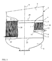
- Figure 1 shows the bottom of a digester partly in section, where the part on the right of the vertical axis of the digester schematically illustrates the conventional fixing arrangement of a screen and the part on the left of the vertical axis schematically illustrates the arrangement of the invention for mounting a screen,
- Figure 2 is a schematic, vertical section of the upper end of the screen, the screen being mounted with the arrangement of the invention,
- Figure 3 is a schematic, vertical section of the lower end of the screen, the screen being mounted with the arrangement of the invention,
- Figure 4 shows a structural detail of the point det. A of Figure 3.
-
- In the following, preferred embodiments of the present arrangement are described with reference to the above-mentioned figures. The arrangement comprises structural parts marked with reference numbers in the figures and corresponding to the reference numbers used in this description.
- With reference to Figure 1, particularly to its part on the righthand side, a conventionally known fixing arrangement of
screens 1 of a continuous pulp digester can be described as follows. The figures show apressure cover 2 of the digester, comprising a second lowest,cylindrical cover section 3, a lowestconical section 4, alowest cover section 5 and abottom end 6. To extend the smaller-diameter cover section 3 of the pressure cover, the region of the conical section is provided with a solidmetal ring plate 7 with a substantially corresponding diameter. The ring plate is thus arranged to guide a cooking flow of chips from the top of the digester to a region where it is subjected to the influence of thescreen 1 serving as an extension for the ring plate. A substantially horizontal upper back-up ring is arranged underneath the conical section in a known manner, the ring supporting the upper edge of the screen and the lower edge of the ring plate onto theinner surface 8 of the pressure cover of the digester. Correspondingly, a lower back-up ring is arranged horizontally on the inner surface of the digester to support the screen at its lower edge. A number of vertical supports required by the screens are arranged between these parallel support rings, whereby the support rings and the vertical supports form a grid-like screen bed. The outer edges of the screens are attached to this screen bed. - The
screens 1 comprise a number of parallel screen bars, which form a screen surface which faces towards thecentral axis 9 of the digester. This screen surface is subjected to force effects of chip flow moving in the digester, which force is arranged to be transmitted to thepressure cover 2 of the digester by means of support rods, i.e. round bars of specific length fixed to the transverse supports. - A
flow space 10 is formed between thescreens 1 mounted on the screen bed and theinner surface 8 of the pressure cover, and by means of acollector tray 11, the flow space is in connection with an outlet fitting 12 which leads liquid out of the digester. - The left part of Figure 1 and Figures 2 to 4 show another specific embodiment with a fully new structure, in which screens 20 are arranged in a continuous pulp digester.
- Since a significant problem of a
conventional screen 20 is too low a filtering capacity in relation to the filtering area, this is solved by extending at least one end - the upper edge 21 - of a screen in a completely new manner to the top end of theconical section 4 which increases the diameter of the pressure vessel forming the digester. The opposite end - the lower edge 22 - of the screen is arranged to extend towards thebottom end 6 of the digester, thus extending, within the limits defined by its construction, as low as possible. - A preferable mounting of the
screen 20 may be at the lowermost part of the digester, whereby the screen is arranged to extend from the top end of the substantially lastconical section 4 to substantially close to a round joint 23 combining the lowermost,cylindrical cover section 5 of the pressure vessel and thebottom end 6 forming the pressure vessel. - This kind of arrangement for mounting
screens 20 at least partly on the region of theconical section 4 comprises a separate screen bed for each individual screen. The screens are thus arranged to be supported bysupport rods 24 which are supported onto theinner surface 8 of the pressure vessel and the length of which can be adjusted. As the length of the support rods can be adjusted, shape deviations of thepressure cover 2, otherwise typical for digesters, can be compensated efficiently. When the support rods are mounted, they are adjusted to extend along the entire length from a frame structure of the screen to theinner surface 8 of the pressure vessel. Thus, all support rods of the uppertransverse support 25 supporting theupper edge 21 of the screen are supported against the inner surface of the pressure vessel. The lowertransverse support 26 supporting thelower edge 22 of the screen in the corresponding manner and at least one intermediate transverse support (not shown) therebetween comprise support rods, which can be supported against the inner surface of the pressure vessel by a simple adjustment. When the support structure for the screens is supported in this way, the allowable load of the screen is not exceeded and the screen bars, which are forming the functional part of the screen being on thescreen surface 27 on the side of the central axis of the digester, remain in their places and fulfil their purpose when filtering the digester liquid. - The height and spread angle of the
conical section 4 which increases the diameter of the pressure vessel are used to define a height for such asheet metal ring 28 that is, if required, arranged to guide a cooking flow of chips from the smaller-diameter region of the digester to the region where it is subjected to the influence of thescreen 20. In extreme cases, i.e. when the upper transverse support supporting the screen'supper edge 21 which, in its operating position, is higher in the digester, is arranged substantially in connection with the joint combining the conical section with the cover section of the pressure vessel above the conical section, no sheet metal ring is required. In an exemplified embodiment according to the figures, the uppertransverse support 25 of thescreen 20 is arranged at the joint 29 above theconical section 4 and combining the pressure vessel with thecover section 3. Usually the height of such a sheet metal ring is 50 mm to 500 mm. Most preferably, the height of the ring is about 200 mm. - As
support rods 24 having an adjustable length are used for supporting thescreens 20, thebackground space 30 between the screen and theinner surface 8 of the pressure vessel according to Figures 2 and 3 can be adjusted by changing the length of the support rods. It can thus be arranged that the background space has a volume allowing the flow rate of chips in the digester to increase and preventing deposits from accumulating in the background space andcollector tubes 29 in connection with it. The screens can thus be arranged in a slightly conical orientation in respect of the inner surface of the pressure vessel. Hence, the inclination of the cone formed by the screens can be adjusted by changing the length of the support rods. - To secure as flexible an operation as possible for the digester and to minimise service breaks, each
screen 20 preferably comprises a separate outlet fitting 31. This outlet fitting is arranged to be in connection with a "header", i.e. a collector tube outside the digester. - The screens can also be mounted in at least partially overlapping zones, each screen preferably having its own outlet fitting.
- It is to be understood that the above description and the related figures are only intended to illustrate the present solution. Thus, the solution is not restricted only to the embodiment described above and defined in the claims, but many different variations and modifications, which are possible within the scope of the idea defined in the attached claims, will be obvious to a person skilled in the art. Thus the bar screen may be used in other continuously operating pressurized and non-pressurized reactors in continuous and batch cooking processes than the digester itself defined above.
Claims (8)
- An arrangement for mounting a screen (20) in a continuous reactor used for making chemical pulp or paper pulp, the reactor comprising a substantially cylindrical vessel arranged in an upright position, the vessel having a smaller diameter at the top end of the reactor than at the bottom end of the reactor, which diameter is arranged to be changed at regionally defined areas by means of one or more conical sections (4), the screens being mounted in connection with the conical sections to remove a desired quantity of liquid from chips or pulp in the reactor, characterized in that
an upper edge (21) of the screen (20), which, in the operating position, is higher in the reactor, is arranged in the region of the conical section (4) and substantially in connection with the section of the conical section, which has the smallest diameter,
and a lower edge (22) of the screen, which, in the operating position, is lower in the reactor, is arranged to be orientated towards the bottom end (6) of the reactor
to maximise the screen area of the reactor. - An arrangement as claimed in claim 1, characterized in that the lower edge (22), which, in the operating position of the screen (20) arranged at the lowermost end of the reactor, is arranged to extend to a round joint (23) combining the lowest, cylindrical cover section (5) and the bottom end (6) forming the bottom of the vessel.
- An arrangement as claimed in claim 1 or 2, characterized in that the screen (20) is arranged to be supported by an upper transverse support (25) supporting the upper edge (21) of the screen and a lower transverse support (26) supporting the lower edge (22) of the screen, which supports are substantially horizontal and parallel
and arranged to be supported against the inner surface (8) of the vessel by means of support rods (24) which combines them. - An arrangement as claimed in claim 3, characterized in that between the upper transverse support (25) and the lower transverse support (26) there is at least one intermediate transverse support, which is parallel with them.
- An arrangement as claimed in claim 3 or 4, characterized in that the support rods (24) are extendable in the longitudinal direction.
- An arrangement as claimed in claim 5, characterized in that the size of a background space of the screen, defined by the screen (20) and the inner surface (8) of the vessel, is adjustable by changing the length of the support rods (24).
- An arrangement as claimed in any one of claims 3 to 6, characterized in that the upper transverse support (25) supporting the upper edge (21) of the screen (20), which, in the operating position, is higher in the reactor, is arranged substantially in connection with a joint combining the conical section (4) and the cover section of the vessel above the conical section.
- An arrangement as claimed in any one of the preceding claims, characterized in that in the vertical direction the reactor is provided with the screens (20) in at least partially overlapping zones.
Applications Claiming Priority (2)
| Application Number | Priority Date | Filing Date | Title |
|---|---|---|---|
| FI20012144 | 2001-11-06 | ||
| FI20012144A FI119107B (en) | 2001-11-06 | 2001-11-06 | Arrangements for installing a strainer |
Publications (2)
| Publication Number | Publication Date |
|---|---|
| EP1316638A1 true EP1316638A1 (en) | 2003-06-04 |
| EP1316638B1 EP1316638B1 (en) | 2007-07-11 |
Family
ID=8562193
Family Applications (1)
| Application Number | Title | Priority Date | Filing Date |
|---|---|---|---|
| EP02102531A Expired - Lifetime EP1316638B1 (en) | 2001-11-06 | 2002-11-05 | Continuous reactor comprising an arrangement for mounting a screen, and a method for mounting a screen to a continuous reactor. |
Country Status (6)
| Country | Link |
|---|---|
| US (1) | US20030095901A1 (en) |
| EP (1) | EP1316638B1 (en) |
| AT (1) | ATE366842T1 (en) |
| CA (1) | CA2409453C (en) |
| DE (1) | DE60221088D1 (en) |
| FI (1) | FI119107B (en) |
Cited By (3)
| Publication number | Priority date | Publication date | Assignee | Title |
|---|---|---|---|---|
| WO2006000642A1 (en) * | 2004-06-29 | 2006-01-05 | Metso Paper, Inc | Screen assembly for a pulp digester |
| WO2013105888A1 (en) * | 2012-01-12 | 2013-07-18 | Metso Paper Sweden Ab | Profile bar screen for digester vessels |
| WO2017099654A1 (en) * | 2015-12-09 | 2017-06-15 | Valmet Ab | Screen for treatment vessels |
Families Citing this family (1)
| Publication number | Priority date | Publication date | Assignee | Title |
|---|---|---|---|---|
| SE538326C2 (en) * | 2014-09-01 | 2016-05-17 | Valmet Oy | Profile bar screen for digester vessels |
Citations (6)
| Publication number | Priority date | Publication date | Assignee | Title |
|---|---|---|---|---|
| WO1987002721A1 (en) * | 1984-05-11 | 1987-05-07 | Rauma-Repola Oy | Method for the separation of gases from the cooking liquor of cellulosic pulp |
| EP0822288A2 (en) * | 1993-11-08 | 1998-02-04 | Ahlstrom Machinery, Inc. | Continuous digester for the implementaion of dissolved solids profiling |
| US6123808A (en) * | 1997-12-09 | 2000-09-26 | Ahlstrom Machinery Inc. | Distribution of dilution liquor to the discharge of a cellulose pulp digester |
| US6129816A (en) * | 1997-10-24 | 2000-10-10 | Andritz-Ahlstrom Inc. | Tapered screen assembly for a cellulose pulp digester |
| WO2001031117A1 (en) * | 1999-10-26 | 2001-05-03 | Bothnia P & P Oy | Bar screen |
| US6277240B1 (en) * | 1998-10-02 | 2001-08-21 | Andritz-Ahlstrom Inc. | Method for continuously pulping cellulosic fibrous material |
-
2001
- 2001-11-06 FI FI20012144A patent/FI119107B/en not_active IP Right Cessation
-
2002
- 2002-10-23 CA CA2409453A patent/CA2409453C/en not_active Expired - Fee Related
- 2002-11-05 EP EP02102531A patent/EP1316638B1/en not_active Expired - Lifetime
- 2002-11-05 AT AT02102531T patent/ATE366842T1/en active
- 2002-11-05 DE DE60221088T patent/DE60221088D1/en not_active Expired - Lifetime
- 2002-11-05 US US10/287,696 patent/US20030095901A1/en not_active Abandoned
Patent Citations (6)
| Publication number | Priority date | Publication date | Assignee | Title |
|---|---|---|---|---|
| WO1987002721A1 (en) * | 1984-05-11 | 1987-05-07 | Rauma-Repola Oy | Method for the separation of gases from the cooking liquor of cellulosic pulp |
| EP0822288A2 (en) * | 1993-11-08 | 1998-02-04 | Ahlstrom Machinery, Inc. | Continuous digester for the implementaion of dissolved solids profiling |
| US6129816A (en) * | 1997-10-24 | 2000-10-10 | Andritz-Ahlstrom Inc. | Tapered screen assembly for a cellulose pulp digester |
| US6123808A (en) * | 1997-12-09 | 2000-09-26 | Ahlstrom Machinery Inc. | Distribution of dilution liquor to the discharge of a cellulose pulp digester |
| US6277240B1 (en) * | 1998-10-02 | 2001-08-21 | Andritz-Ahlstrom Inc. | Method for continuously pulping cellulosic fibrous material |
| WO2001031117A1 (en) * | 1999-10-26 | 2001-05-03 | Bothnia P & P Oy | Bar screen |
Cited By (7)
| Publication number | Priority date | Publication date | Assignee | Title |
|---|---|---|---|---|
| WO2006000642A1 (en) * | 2004-06-29 | 2006-01-05 | Metso Paper, Inc | Screen assembly for a pulp digester |
| CN101018906B (en) * | 2004-06-29 | 2010-06-16 | 美特索造纸公司 | Screen assemblies for pulp digesters |
| WO2013105888A1 (en) * | 2012-01-12 | 2013-07-18 | Metso Paper Sweden Ab | Profile bar screen for digester vessels |
| CN104053834A (en) * | 2012-01-12 | 2014-09-17 | 维美德公司 | Profile bar screen for digester vessels |
| US8980061B2 (en) | 2012-01-12 | 2015-03-17 | Valmet Ab | Profile bar screen for digester vessels |
| CN104053834B (en) * | 2012-01-12 | 2016-04-06 | 维美德公司 | For the special bar screen of digester vessel |
| WO2017099654A1 (en) * | 2015-12-09 | 2017-06-15 | Valmet Ab | Screen for treatment vessels |
Also Published As
| Publication number | Publication date |
|---|---|
| FI20012144L (en) | 2003-05-07 |
| CA2409453C (en) | 2010-12-14 |
| CA2409453A1 (en) | 2003-05-06 |
| FI20012144A0 (en) | 2001-11-06 |
| DE60221088D1 (en) | 2007-08-23 |
| EP1316638B1 (en) | 2007-07-11 |
| ATE366842T1 (en) | 2007-08-15 |
| US20030095901A1 (en) | 2003-05-22 |
| FI119107B (en) | 2008-07-31 |
Similar Documents
| Publication | Publication Date | Title |
|---|---|---|
| FI115142B (en) | Boilers for continuous cooking of fiber material | |
| EP1316638B1 (en) | Continuous reactor comprising an arrangement for mounting a screen, and a method for mounting a screen to a continuous reactor. | |
| EP3189188B1 (en) | Profile bar screen for digester vessels | |
| EP0068558B1 (en) | Moving catalyst bed reactor | |
| US8980061B2 (en) | Profile bar screen for digester vessels | |
| US7566380B2 (en) | Continuous digester with fluid circulation | |
| US5744005A (en) | Self-supporting straining device for a continuous digester | |
| US7736467B2 (en) | Screen assembly for a pulp digester | |
| JP5174183B2 (en) | Cooking kiln screen for continuous cellulose pulp cooking kiln | |
| EP2295631B1 (en) | Pressure diffuser internal guide | |
| WO1995016817A1 (en) | Screen device | |
| EP2994567B1 (en) | An apparatus for washing and/or dewatering pulp and an method for mounting an insert in an apparatus for washing and dewatering pulp | |
| WO2011096857A1 (en) | Continuous digester with improved heating circulation | |
| WO2024057074A1 (en) | Screen support assembly and screen plate | |
| WO2011078775A1 (en) | Method and arrangement for improving a washing step after completed cooking in a continuous digester |
Legal Events
| Date | Code | Title | Description |
|---|---|---|---|
| PUAI | Public reference made under article 153(3) epc to a published international application that has entered the european phase |
Free format text: ORIGINAL CODE: 0009012 |
|
| AK | Designated contracting states |
Designated state(s): AT BE BG CH CY CZ DE DK EE ES FI FR GB GR IE IT LI LU MC NL PT SE SK TR |
|
| AX | Request for extension of the european patent |
Extension state: AL LT LV MK RO SI |
|
| 17P | Request for examination filed |
Effective date: 20031006 |
|
| AKX | Designation fees paid |
Designated state(s): AT BE BG CH CY CZ DE DK EE ES FI FR GB GR IE IT LI LU MC NL PT SE SK TR |
|
| 17Q | First examination report despatched |
Effective date: 20040420 |
|
| GRAP | Despatch of communication of intention to grant a patent |
Free format text: ORIGINAL CODE: EPIDOSNIGR1 |
|
| RTI1 | Title (correction) |
Free format text: CONTINUOUS REACTOR COMPRISING AN ARRANGEMENT FOR MOUNTING A SCREEN, AND A METHOD FOR MOUNTING A SCREEN TO A CONTINUOUS REACTOR. |
|
| GRAS | Grant fee paid |
Free format text: ORIGINAL CODE: EPIDOSNIGR3 |
|
| GRAA | (expected) grant |
Free format text: ORIGINAL CODE: 0009210 |
|
| AK | Designated contracting states |
Kind code of ref document: B1 Designated state(s): AT BE BG CH CY CZ DE DK EE ES FI FR GB GR IE IT LI LU MC NL PT SE SK TR |
|
| REG | Reference to a national code |
Ref country code: GB Ref legal event code: FG4D |
|
| REG | Reference to a national code |
Ref country code: CH Ref legal event code: EP |
|
| REF | Corresponds to: |
Ref document number: 60221088 Country of ref document: DE Date of ref document: 20070823 Kind code of ref document: P |
|
| REG | Reference to a national code |
Ref country code: IE Ref legal event code: FG4D |
|
| REG | Reference to a national code |
Ref country code: SE Ref legal event code: TRGR |
|
| PG25 | Lapsed in a contracting state [announced via postgrant information from national office to epo] |
Ref country code: NL Free format text: LAPSE BECAUSE OF FAILURE TO SUBMIT A TRANSLATION OF THE DESCRIPTION OR TO PAY THE FEE WITHIN THE PRESCRIBED TIME-LIMIT Effective date: 20070711 Ref country code: ES Free format text: LAPSE BECAUSE OF FAILURE TO SUBMIT A TRANSLATION OF THE DESCRIPTION OR TO PAY THE FEE WITHIN THE PRESCRIBED TIME-LIMIT Effective date: 20071022 Ref country code: PT Free format text: LAPSE BECAUSE OF FAILURE TO SUBMIT A TRANSLATION OF THE DESCRIPTION OR TO PAY THE FEE WITHIN THE PRESCRIBED TIME-LIMIT Effective date: 20071211 Ref country code: BG Free format text: LAPSE BECAUSE OF FAILURE TO SUBMIT A TRANSLATION OF THE DESCRIPTION OR TO PAY THE FEE WITHIN THE PRESCRIBED TIME-LIMIT Effective date: 20071011 Ref country code: FI Free format text: LAPSE BECAUSE OF FAILURE TO SUBMIT A TRANSLATION OF THE DESCRIPTION OR TO PAY THE FEE WITHIN THE PRESCRIBED TIME-LIMIT Effective date: 20070711 |
|
| REG | Reference to a national code |
Ref country code: CH Ref legal event code: PL |
|
| NLV1 | Nl: lapsed or annulled due to failure to fulfill the requirements of art. 29p and 29m of the patents act | ||
| PG25 | Lapsed in a contracting state [announced via postgrant information from national office to epo] |
Ref country code: LI Free format text: LAPSE BECAUSE OF FAILURE TO SUBMIT A TRANSLATION OF THE DESCRIPTION OR TO PAY THE FEE WITHIN THE PRESCRIBED TIME-LIMIT Effective date: 20070711 Ref country code: CH Free format text: LAPSE BECAUSE OF FAILURE TO SUBMIT A TRANSLATION OF THE DESCRIPTION OR TO PAY THE FEE WITHIN THE PRESCRIBED TIME-LIMIT Effective date: 20070711 |
|
| EN | Fr: translation not filed | ||
| PG25 | Lapsed in a contracting state [announced via postgrant information from national office to epo] |
Ref country code: BE Free format text: LAPSE BECAUSE OF FAILURE TO SUBMIT A TRANSLATION OF THE DESCRIPTION OR TO PAY THE FEE WITHIN THE PRESCRIBED TIME-LIMIT Effective date: 20070711 |
|
| PG25 | Lapsed in a contracting state [announced via postgrant information from national office to epo] |
Ref country code: GR Free format text: LAPSE BECAUSE OF FAILURE TO SUBMIT A TRANSLATION OF THE DESCRIPTION OR TO PAY THE FEE WITHIN THE PRESCRIBED TIME-LIMIT Effective date: 20071012 Ref country code: DK Free format text: LAPSE BECAUSE OF FAILURE TO SUBMIT A TRANSLATION OF THE DESCRIPTION OR TO PAY THE FEE WITHIN THE PRESCRIBED TIME-LIMIT Effective date: 20070711 |
|
| PLBE | No opposition filed within time limit |
Free format text: ORIGINAL CODE: 0009261 |
|
| STAA | Information on the status of an ep patent application or granted ep patent |
Free format text: STATUS: NO OPPOSITION FILED WITHIN TIME LIMIT |
|
| PG25 | Lapsed in a contracting state [announced via postgrant information from national office to epo] |
Ref country code: CZ Free format text: LAPSE BECAUSE OF FAILURE TO SUBMIT A TRANSLATION OF THE DESCRIPTION OR TO PAY THE FEE WITHIN THE PRESCRIBED TIME-LIMIT Effective date: 20070711 Ref country code: SK Free format text: LAPSE BECAUSE OF FAILURE TO SUBMIT A TRANSLATION OF THE DESCRIPTION OR TO PAY THE FEE WITHIN THE PRESCRIBED TIME-LIMIT Effective date: 20070711 |
|
| 26N | No opposition filed |
Effective date: 20080414 |
|
| PG25 | Lapsed in a contracting state [announced via postgrant information from national office to epo] |
Ref country code: MC Free format text: LAPSE BECAUSE OF NON-PAYMENT OF DUE FEES Effective date: 20071130 |
|
| GBPC | Gb: european patent ceased through non-payment of renewal fee |
Effective date: 20071105 |
|
| PG25 | Lapsed in a contracting state [announced via postgrant information from national office to epo] |
Ref country code: DE Free format text: LAPSE BECAUSE OF FAILURE TO SUBMIT A TRANSLATION OF THE DESCRIPTION OR TO PAY THE FEE WITHIN THE PRESCRIBED TIME-LIMIT Effective date: 20071012 Ref country code: FR Free format text: LAPSE BECAUSE OF FAILURE TO SUBMIT A TRANSLATION OF THE DESCRIPTION OR TO PAY THE FEE WITHIN THE PRESCRIBED TIME-LIMIT Effective date: 20080307 |
|
| PG25 | Lapsed in a contracting state [announced via postgrant information from national office to epo] |
Ref country code: IE Free format text: LAPSE BECAUSE OF NON-PAYMENT OF DUE FEES Effective date: 20071105 |
|
| PG25 | Lapsed in a contracting state [announced via postgrant information from national office to epo] |
Ref country code: GB Free format text: LAPSE BECAUSE OF NON-PAYMENT OF DUE FEES Effective date: 20071105 |
|
| PG25 | Lapsed in a contracting state [announced via postgrant information from national office to epo] |
Ref country code: EE Free format text: LAPSE BECAUSE OF FAILURE TO SUBMIT A TRANSLATION OF THE DESCRIPTION OR TO PAY THE FEE WITHIN THE PRESCRIBED TIME-LIMIT Effective date: 20070711 |
|
| PG25 | Lapsed in a contracting state [announced via postgrant information from national office to epo] |
Ref country code: CY Free format text: LAPSE BECAUSE OF FAILURE TO SUBMIT A TRANSLATION OF THE DESCRIPTION OR TO PAY THE FEE WITHIN THE PRESCRIBED TIME-LIMIT Effective date: 20070711 |
|
| PG25 | Lapsed in a contracting state [announced via postgrant information from national office to epo] |
Ref country code: LU Free format text: LAPSE BECAUSE OF NON-PAYMENT OF DUE FEES Effective date: 20071105 |
|
| PG25 | Lapsed in a contracting state [announced via postgrant information from national office to epo] |
Ref country code: TR Free format text: LAPSE BECAUSE OF FAILURE TO SUBMIT A TRANSLATION OF THE DESCRIPTION OR TO PAY THE FEE WITHIN THE PRESCRIBED TIME-LIMIT Effective date: 20070711 |
|
| PG25 | Lapsed in a contracting state [announced via postgrant information from national office to epo] |
Ref country code: IT Free format text: LAPSE BECAUSE OF NON-PAYMENT OF DUE FEES Effective date: 20071130 |
|
| PGFP | Annual fee paid to national office [announced via postgrant information from national office to epo] |
Ref country code: SE Payment date: 20181120 Year of fee payment: 17 Ref country code: AT Payment date: 20181121 Year of fee payment: 17 |
|
| REG | Reference to a national code |
Ref country code: SE Ref legal event code: EUG |
|
| REG | Reference to a national code |
Ref country code: AT Ref legal event code: MM01 Ref document number: 366842 Country of ref document: AT Kind code of ref document: T Effective date: 20191105 |
|
| PG25 | Lapsed in a contracting state [announced via postgrant information from national office to epo] |
Ref country code: SE Free format text: LAPSE BECAUSE OF NON-PAYMENT OF DUE FEES Effective date: 20191106 |
|
| PG25 | Lapsed in a contracting state [announced via postgrant information from national office to epo] |
Ref country code: AT Free format text: LAPSE BECAUSE OF NON-PAYMENT OF DUE FEES Effective date: 20191105 |