-
The present invention relates to hybrid electric
vehicles and in particular to matching engine and generator
torques in a hybrid electric vehicle.
-
Generally, a hybrid electric vehicle combines electric
propulsion with traditional internal combustion engine
propulsion to achieve enhanced fuel economy and/or lower
exhaust emissions. Electric propulsion has typically been
generated through the use of batteries and electric motors.
Such an electric propulsion system provides the desirable
characteristics of high torque at low speeds, high
efficiency, and the opportunity to recapture otherwise lost
braking energy. Propulsion from an internal combustion
engine provides high energy density, and enjoys an existing
infrastructure and lower costs due to economies of scale.
By combining the two propulsive systems with a proper
control strategy, the result is a reduction in the use of
each device in its less efficient range. Furthermore, and as
shown in Figure 1 regarding a parallel hybrid configuration,
the combination of a downsized engine with an electric
propulsion system into a minimal hybrid electric vehicle
results in a better utilization of the engine, which
improves fuel consumption. Furthermore, the electric motor
and battery can compensate for reduction in the engine size.
-
In typical configurations, the combination of the two
types of propulsion systems (internal combustion and
electric) is usually characterized as either series or
parallel hybrid systems. In a pure series hybrid propulsion
system, only the electric motor(s) are in direct connection
with the drive train and the engine is used to generate
electricity which is fed to the electric motor(s). The
advantage of this type of system is that the engine can be
controlled independently of driving conditions and can
therefore be consistently run in its optimum efficiency and
low emission ranges. A key disadvantage to the series
arrangement is the loss in energy experienced because of the
inefficiencies associated with full conversion of the engine
output to electricity.
-
In a pure parallel hybrid propulsion system, both the
engine and the electric motor(s) are directly connected to
the drive train and either one may independently drive the
vehicle. Because there is a direct mechanical connection
between the engine and the drive train in a parallel hybrid
propulsion system, less energy is lost through conversion to
electricity compared to a series hybrid propulsion system.
The operating point for the engine, however, can not always
be chosen with full freedom.
-
The two hybrid propulsion systems can be combined into
either a switching hybrid propulsion system or a power-split
hybrid propulsion system. A switching hybrid propulsion
system typically includes an engine, a generator, a motor
and a clutch. The engine is typically connected to the
generator. The generator is connected through a clutch to
the drive train. The motor is connected to the drive train
between the clutch and the drive train. The clutch can be
operated to allow series or parallel hybrid propulsion.
-
A power-split hybrid system, as is exemplarily employed
with respect to the present invention, includes an engine, a
generator and a motor. The engine output is "split" by a
planetary gear set into a series path from the engine to the
generator and a parallel path from the engine directly to
the power train. In a power-split hybrid system, the engine
speed can be controlled by varying the power split to the
generator by way of the series path, while maintaining the
mechanical connection between the engine and drive train
through the parallel path. The motor augments the engine on
the parallel path in a similar manner as a traction motor in
a pure parallel hybrid propulsion system, and provides an
opportunity to use energy directly through the series path,
thereby reducing the losses associated with converting the
electrical energy into, and out of chemical energy at the
battery.
-
In a typical power-split hybrid system, the generator
is usually connected to the sun gear of the planetary gear
set. The engine is connected to the planetary carrier and
the output gears (usually including an output shaft and
gears for interconnection with the motor and the wheel-powering,
final drive train) are connected to the ring gear.
In such a configuration, the power-split hybrid system can
generally be operated in four different modes; one electric
mode and three hybrid modes.
-
In the electric mode, the power-split hybrid system
propels the vehicle utilizing only stored electrical energy
and the engine is turned off. The tractive torque is
supplied from the motor, the generator, or a combination of
both. This is the preferred mode when the desired power is
low enough that it can be produced more efficiently by the
electrical system than by the engine and when the battery is
sufficiently charged. This is also a preferred mode for
reverse driving because the engine cannot provide reverse
torque to the power train in this configuration.
-
In the parallel hybrid mode, the engine is operating
and the generator is locked. By doing this, a fixed
relationship between the speed of the engine and the vehicle
speed is established. The motor operates as either a motor
to provide tractive torque to supplement the engine's power,
or can be operated to produce electricity as a generator.
This is a preferred mode whenever the required power demand
requires engine operation and the required driving power is
approximately equal to an optimized operating condition of
the engine. This mode is especially suitable for cruising
speeds exclusively maintainable by the small internal
combustion engine fitted to the hybrid electric vehicle.
-
In a positive split hybrid mode, the engine is on and
its power is split between a direct mechanical path to the
drive train and an electrical path through the generator.
The engine speed in this mode is typically higher than the
engine speed in the parallel mode, thus deriving higher
engine power. The electrical energy produced by the
generator can flow to the battery for storage or to the
motor for immediate utilization. In the positive split
mode, the motor can be operated as either a motor to provide
tractive torque to supplement the engine's power or to
produce electricity to supplement the generator. This is
the preferred mode whenever high engine power is required
for tractive powering of the vehicle, such as when high
magnitude acceleration is called for, as in passing or
uphill ascents. This is also a preferred mode when the
battery is charging.
-
In a negative split hybrid mode, the engine is in
operation and the generator is being used as a motor against
the engine to reduce its speed. Consequently, engine speed,
and therefore engine power, are lower than in parallel mode.
If needed, the motor can also be operated to provide
tractive torque to the drive train or to generate
electricity therefrom. This mode is typically never
preferred due to increased losses at the generator and
planetary gear system, but will be utilized when engine
power is required to be decreased below that which would
otherwise be produced in parallel mode. This situation will
typically be brought about because the battery is in a well
charged condition and/or there is low tractive power demand.
In this regard, whether operating as a generator or motor,
the toque output of the generator is always of the same
sense (+/-); that is, having a torque that is always
directionally opposed to that of the engine. The sign of
the speed of the generator, however, alternates between
negative and positive values depending upon the direction of
rotation of its rotary shaft, which corresponds with
generator vs. motor modes. Because power is dependent upon
the sense of the speed (torque remains of the same sense),
the power will be considered to be positive when the
generator is acting as a generator and negative when the
generator is acting as a motor.
-
When desiring to slow the speed of the engine, the
current being supplied to the generator is changed causing
the speed of the generator to slow. Through the planetary
gear set, this in turn slows the engine. This effect is
accomplished because the resistive force acting against the
torque of the generator is less at the engine than at the
drive shaft which is connected to the wheels and is being
influenced by the entire mass of the vehicle. It should be
appreciated that the change in speed of the generator is not
equal, but instead proportional to that of the engine
because of gearing ratios involved within the connection
therebetween.
-
In electric and hybrid electric vehicles, large
capacity electricity storage device(s), usually in the form
of battery packs, are required. By conventional design,
these batteries include a plurality of cylindrical battery
cells that are collectively utilized to obtain sufficient
performance and range in the vehicle. Typically, batteries
are positioned within the vehicle in a compartment
configured to protect against damage and to prevent the
cells, and mostly their acidic contents, from causing injury
or damage, especially in the event of a crash. When stored
in these typically confined compartment(s), heat build-up
generated from use and/or charging affects the endurance of
the batteries, and in some circumstances can destroy
individual battery cells. Traditional cooling of the
batteries and the battery compartment requires increasing
the volume of the compartment for air cooling and/or running
cooling hoses to external radiators.
-
Typically, to achieve a smooth engine start in a hybrid
electric vehicle in which the engine is mechanically
interconnected with the drive wheels, the start of engine
fuel injection and ignition are made at revolutionary speeds
above any mechanical resonance speeds of the drive train.
Additionally, at full take-off acceleration, any delay in
the engine's production of power typically decreases engine
performance. Still further, to achieve smooth driving
characteristics and obtain low fuel consumption, the engine
torque and speed change rates must be limited. At full
take-off, this usually results in an increased time period
for the engine to reach maximum power, and all of these
conditions deteriorate acceleration performance of the
vehicle.
-
As can be appreciated, the engine is not always running
during vehicle operation. If the engine is stopped for a
sufficiently long period during the operation of the
vehicle, the exhaust system catalyst may cool down too much,
and to such a degree that a temporary, but significant
increase in exhaust emissions occur upon restart and until
the catalyst once again warms to its effective temperature.
-
In another aspect, the battery state-of-charge (SOC) in
a hybrid electric vehicle is typically controlled using SOC
feedback control. When applying SOC feedback control,
however, and when the vehicle is operating in a low velocity
region, the SOC feedback control tends to grow unstable as
velocity increases. Instability also occurs when the
vehicle is operating at high velocity and the velocity of
the vehicle then decreases. The same instability or
weakness can still occur even when using "feed-forward" type
estimating of required tractive force; the same being a
typical complement to SOC feedback control. This is
particularly true at low vehicle velocities with velocity
increases and at high vehicle velocities with velocity
decreases. Even when properly designed, the SOC feedback
control can also be weak at full take-off.
-
In a typical power-split hybrid electric propulsion
arrangement, the control strategy advantageously involves
operating the engine along optimum efficiency torque vs.
speed curves. A trade-off exists between traction force
performance and fuel economy which, for optimization,
typically requires selection of a particular gear ratio
between the engine and the wheels that causes the engine to
deliver more power than is needed for vehicle propulsion.
This generally occurs at cruising in parallel mode, or near
constant vehicle velocity conditions. Operation under these
conditions can, sometimes, cause the battery and charging
system to reject energy being presented thereto from the
engine. This problem is generally solved by decreasing or
limiting the engine output power by entering negative split
mode which entails using the generator as a motor to control
the engine to a decreased speed. Such control allows the
engine to follow an optimum curve at reduced engine output
power.
-
Use of the generator as a motor gives rise to a power
circulation in the power-train which leads to undesirable
energy losses at the generator, motor, inverters and/or
planetary gear set. These energy losses may be manifest as
heat generation which indicates that most efficient use is
not being made of the installed drive train.
-
In a power-split hybrid propulsion system having
planetary gear set(s) and utilizing a generator lock-up
device, a harshness in ride occurs when the generator lock-up
device is engaged or released. This is due primarily to
the difference in how engine torque is estimated when the
vehicle is in different operating modes. Typically, when
the generator is locked up, engine torque is estimated from
the combustion control process of the engine. When the
generator is free, as in split mode, however, engine torque
is estimated from the generator torque control process. The
difference in values of these two estimating techniques
gives rise to what usually amounts to a variation in
operating torque between the engine and generator when the
lock-up device is engaged or disengaged, thereby creating
harshness in the vehicle's operation, usually manifest as
abrupt changes or jerkiness in the vehicle's ride.
-
As earlier indicated, the generator is typically used
to control the engine in power-split hybrid mode. This is
usually accomplished by employing a generator having maximum
torque capabilities substantially greater than the engine's
maximum torque that is transmittable to the planetary gear
system. Failure to have such a control margin can result in
generator over-speed and possible damage to the propulsion
system. Such a control margin means, however, that the
engine and generator are not fully exploited at full
capacity acceleration.
-
It is an object of this invention to provide an
improved method for use in a hybrid electric vehicle.
-
According to a first aspect of the invention there is
provided a method for calibrating and synchronising sensed
operating torques of an engine and a generator in a
planetary gear based hybrid electric vehicle characterised
in that the method comprises providing a sensor that detects
the operational torque of the engine of the hybrid electric
vehicle at the interface of the engine with a planetary gear
system of the hybrid electric vehicle, providing a sensor
that detects the operational torque of the generator,
operating the planetary gear system of the hybrid electric
vehicle in a split mode so that the generator is directly
linked to the engine and a reading of the sensor that
detects the operational torque of the generator may be used
to compute the operating torque of the engine recording
paired values of sensed operational torques of said engine
and said generator at like times, arithmetically processing
each pair of recorded values and computing a calibrating
value therebetween, repeating the sensing and recording of
paired values at the same sensed generator and engine speeds
and torques thereby enabling the calculation of computed
average calibrating values at each of the particular sensed
generator speeds suitable for subsequent utilisation in
computing corresponding engine torques in the future and
controlling the engine and the generator utilizing the
average calibrating value at future times of transition
between power-split mode and parallel mode of the planetary
gear system so that the engine is substantially synchronized
with the generator at the time of direct linkage across the
planetary gear arrangement thereby avoiding driver
detectible irregularities in the performance of the power
train of the hybrid electric vehicle.
-
Preferably, a plurality of calibrating values may be
considered so that different calibration factors can be
obtained for different operation points for the engine and
generator thereby maximising the predictive quality of the
average calibrating factor.
-
The relationship between the engine and generator in
the split mode may be based on gear ratios that are
substantially unchanging.
-
The method may further comprise recording
contemporaneous values of complementary operating parameters
of the hybrid electric vehicle for each pair of recorded
values of sensed operational torques of said engine and said
generator at specific times.
-
The method may further comprise permitting the average
calibration value to be varied by a limited maximum value
with respect to time so that anomalous disturbances do not
significantly impact the computed average calibration value.
-
The method may further comprise continuously updating
the computed average calibration value for a particular
generator sensed torque thereby continuously improving the
quality of the average calibration value for that particular
generator sensed torque.
-
The irregularities to be avoided may be manifest as
jerking motions induced in the hybrid electric vehicle by
the planetary gear system.
-
The method may further comprise enabling customisation
of the computed average calibration value to an individual
vehicle.
-
According to a second aspect of the invention there is
provided a hybrid electric vehicle having an internal
combustion engine, an electric motor, an electric generator,
a planetary gear system and at least one electronic
controller to control operation of the hybrid electric
vehicle characterised in that the vehicle further comprises
a sensor to detect the operational torque of the engine at
the interface of the engine with the planetary gear system,
a sensor to detect the operational torque of the generator,
operating the planetary gear system in a split mode so that
the generator is directly linked to the engine and a reading
of the sensor that detects the operational torque of the
generator may be used to compute the operating torque of the
engine, electronically storing in one of said controllers
paired values of sensed operational torques of said engine
and said generator at like times, at least one controller
being operable to arithmetically process each pair of
recorded values and compute a calibrating value
therebetween, repeating the sensing and recording of paired
values at the same sensed generator and engine speeds and
torques thereby enabling the calculation of computed average
calibrating values at each of the particular sensed
generator speeds suitable for subsequent utilisation in
computing corresponding engine torques wherein at least one
controller is operable to control the engine and the
generator by utilising the average calibrating value during
transition between a power-split mode and a parallel mode of
operation of the planetary gear system so that the engine is
substantially synchronised with the generator at the time of
direct linkage across the planetary gear arrangement thereby
avoiding driver detectible irregularities in the performance
of the power train of the hybrid electric vehicle.
-
The invention will now be described by way of example
with reference to the accompanying drawing of which:-
- In the following, the invention will be described in
greater detail by way of examples and with reference to the
attached drawings, in which:
- Figure 1 is a graphical comparison of torque generated
by a parallel hybrid and systems that have either an engine
or motor;
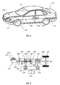
- Figure 2 is a perspective of a hybrid electric vehicle
showing system component locations on the vehicle;
- Figure 3 is a schematic depicting the architecture of a
power-split hybrid electric vehicle;
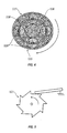
- Figure 4 is a cross-sectional schematic representation
of a planetary gear set;
- Figure 5 is a simplified schematic view of a one-way
clutch shown in Figure 2;
- Figure 6 is a schematic depicting control relationships
between the various systems of a hybrid electric vehicle as
coordinated utilizing a controller area network;
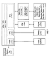
- Figure 7 is a functional schematic depicting the
specific processes, tasks and controls of the various
systems used by a hybrid electric vehicle in accordance with
this invention;
- Figure 8a is a schematic horizontal cross-sectional
view of a battery for a hybrid electric vehicle;
- Figure 8b is a schematic horizontal cross-sectional
view of a traditional battery having cylindrically-shaped
cells;
- Figure 8c is a schematic vertical cross-sectional view
of a battery cooling system as depicted in Figure 8a;
- Figures 9 and 10 schematically illustrate a method for
minimizing driver perceptible drive train disturbances
during take-off in a hybrid electric vehicle;
- Figures 11 through 15 schematically illustrate a method
for maximising the utilisable torque output of a
particularly sized engine in a hybrid electric vehicle.
As shown in Figures 1 and 2, a hybrid electric
transporting vehicle 10 has a power train system having
components generally designated with reference numbers from
the 500's series included therein for providing propulsion,
as well as serving supplemental functions which are
described in greater detail herein.The power train system is positioned in an engine room
11 located near a passenger compartment 12 of the vehicle
10. A battery compartment or housing 14, also positioned
near the passenger compartment 12 holds one or more
batteries 410. As will be appreciated by those skilled in
the art, the positioning of both the engine room 11 and
battery housing 14 is not limited to the locations set forth
in Figure 2. For example, either may be positioned in front
of, or behind the passenger compartment 12.As depicted in Figure 2, the overall systems
architecture of the electric hybrid vehicle 10 comprises an
engine system 510, including an internal combustion engine
511 that is mechanically connected by an output shaft system
520 to a transaxle system 530.The transaxle system 530 is further connected to a
drive shaft system 540 utilized to rotate one or more drive
wheels 20 that propel the hybrid electric transporting
vehicle 10.The combustion engine 511 is controlled by an engine
control module (ECM) or unit 220 which is capable of
adjusting, among possible parameters, airflow to, fuel flow
to and/or ignition at the engine 511. The engine 511 is
mechanically connected via an output shaft 522 to the
transaxle system 530. A planetary gear set 535 establishes
interconnection between the engine 511 via the output shaft
522, a generator 532, and the drive shaft system 540 via the
transaxle system 530. A motor 531 is also coupled to the
drive shaft system 540, also possibly via the transaxle
system 530.In the embodiment shown in Figures 3 and 5, a one way
clutch 521 is engageable with the output shaft 522, which in
turn is connect to the engine 511 and to the planetary gear
set 535. The function of the one-way clutch 521 is to limit
the engine to being only a power/torque input to the
planetary gear set 535, and with only one direction of
rotation. Consequently, the one-way clutch 521 prevents
power or torque from being transmitted from the planetary
gear set 535 back to the engine 511.As shown in Figure 4, the planetary gear set 535
comprises a plurality of concentrically positioned planet
gears 539 mechanically engaged between a perimeter region of
a centrally located sun gear 538 and an interior surface of
a ring gear 537. The individual gears that make up the
plurality or set of planet gears 539 are fixed in positions
relative to each other by a planetary carrier 536.The generator 532 is mechanically connected to the sun
gear 538 and is configured to convey rotational power and
torque to and from the planetary gear set 535. In a
preferred embodiment, the generator 532 is capable of being
locked to prevent rotation of the sun gear 538 by a
generator brake or lock-up device 533. As further
contemplated by the present invention, the motor 531 is
mechanically connected to the ring gear 537 and is
configured to convey rotational power and torque to and from
the planetary gear set 535. In a preferred embodiment shown in Figure 3, the drive
shaft system 540 is engageable with the motor 531 and
effectively terminates at the drive wheel 20, via a
conventionally configured transmission/differential
arrangement 542.Based on the above disclosed system architecture,
implementation of an energy management strategy, which is a
focus of the hybrid electric vehicle 10, starts at a high
level within a vehicle control unit or vehicle systems
controller (VCU)100 as schematically shown in Figures 6 and
7.The vehicle systems controller 100 is programmed with
control strategies for the drive train system and battery
system, as well as others and is responsible for
interpreting driver inputs, coordinating the component
controllers, and determining vehicle system operating
states.The VCU 100 also generates commands to appropriate
component sub-systems based on defined vehicle systems
controller 100 functions, and sends those commands to the
component controllers that, based thereon, take appropriate
actions and acts as a reference signal generator for the
sub-system controllers.The vehicle systems controller 100 may take the form of
a single, integrated microprocessor, or comprise multiple
microprocessors or controllers that are suitably
interconnected and co-ordinated.A primary function of the vehicle systems controller
100 is to carry out vehicle mode processes and tasks known
as the sequential control process this is in addition to
making torque determinations, setting reference values and
performing energy management processes. Certain systems of
the vehicle 10 are managed or monitored by a vehicle
management (VM) unit or controller 105 which carries out
sequential control processes, including ascertaining the
position of the vehicle key and gear selector positioning,
among others. It is at this level that certain inputs from
the driver and conditions of the vehicle are synthesized for
utilization as command inputs for sub-system controllers.At the lower level of the VCU 100, three sub-component
controllers are illustrated in Figure 7. The first is a
high voltage DC controller (HVDC) 115; the second is a
battery management unit or controller 110 (BMU); and the
third is a drive train controller 120 (DTC). As indicated
above, certain inputs and processes are taken from the
driver and the vehicle's systems at the vehicle management
unit 105. Conversely, certain outputs relevant to the
driver will be transmitted and displayed at the dashboard
display unit 107 from the VCU 100 or the VM 105.The HVDC 115 is responsible for coordinating operation
of the high voltage components. The positioning of this
controller is schematically shown in Figure 6. The HVDC
contains contactors or breakers which are normally
positioned to an open configuration that prevents
electricity from flowing across. But when called on to take
action and engage the battery 410, for instance when
starting of the engine 511 is required, these contactors
close completing an appropriate connective circuit.As shown in Figure 6, the HVDC serves as a shield or
buffer between the high voltage battery 410, and the
inverters 534, as well as other auxiliary loads run off of
the electric power of the battery 410. An example of such a
high voltage auxiliary load may include an electrically run
air-conditioning compressor system. In order to act as such
a buffer, the high voltage output from the battery 410 must
be relatively slowly "brought-up" to operating levels at the
inverter 534 and/or auxiliary loads. In order to accept
this "run-up" of the voltage, relatively small capacity
contactors are initially closed that cause voltage from the
battery to pass to a capacitor in either the inverter 534 or
the appropriate auxiliary load, across a resistive circuit
(a circuit containing buffering resistors). Once an
appropriate pre-charge is built-up in the capacitor, primary
contractors are then closed which complete the high voltage
circuit between the batteries 410 and the capacitor
contained within the receiving component which may be
exemplified by the DC to AC inverter(s) 534, or an auxiliary
load such as an electric air-conditioning system as
indicated hereinabove. In this manner, a potentially
damaging high voltage is prevented from being introduced too
quickly to the receiving components.The HVDC 115 also carries out certain diagnostic
functions regarding the components of the HVDC 115, such as
the contactors within the HVDC 115 itself, and also possibly
the several systems interconnected through the HVDC, such as
the battery 410, the inverters 534, or an electrically
driven air-conditioning compressor which has not been
illustrated in the Figures. Among other parameters, these
diagnostics may be performed based on measurements of
voltage and/or current.The HVDC 115 also provides interconnection between an
exterior charger connection, see Figure 6, thereby allowing
the battery 410 to be "plugged-in" for charging from an
external power source.The battery management controller (BMU) 110 handles
control tasks relative to the battery system 410. Among
other characteristics, the BMU 110 can estimate and measure
state-of-charge (SOC) levels, and voltage and current
parameters. It can also sense/determine and maintain
maximum and minimum voltage and current levels with respect
to the battery 410. Based on these determinations or sensed
quantities/qualities, the VM 105 , via such control modules
as the DTC 120, can direct certain operations for affecting
changes in the SOC of the battery 410. Other
characteristics which may be monitored include operating
temperature(s) of the battery 410, and voltages at the
individual battery cells 412. Similarly, pressure within
the cells 412 can also be monitored. Failures may be
detected and reported, at least back to the VCU; but there
is also the possibility of the information being passed to
the operator via the dashboard display unit 107.The DTC 120 makes the mode selection under which the
several powering components will cooperate. That includes
choices between parallel and split modes, as well as
positive and negative split modes. The operational points
for the several components of the drive train are also
specified by the DTC 120. Still further, reference values
are provided by the DTC 120 for the several sub-sytems,
including the transaxle management control modules or unit
(TMU) 230 and the engine control module or unit (ECM) 220.
From among the possible settings established by the DTC 120,
battery charging/discharging mode is a possibility, as well
as specifying whether the generator 532 and/or motor 531
should be used in their powering capacity as a motor, or
their generating capacity as a generator. Torque references
for the generator and motor are also issued from the TMU
230.As a sub-component under the TMU 230, the transaxle
control unit TCU 232 handles the transaxle 530 with respect
to torque compensation when starting and stopping the engine
511. The TCU 232 uses and controls two slave processors
characterized as a generator control unit GCU 236 and a
motor control unit MCU 234. The GCU 236 handles the current
and torque control of the generator 532; typically, via the
inverter 534. The GCU 236 receives its torque and speed
reference information from the TCU 232 as its immediate
controller. The TCU 232 receives a total torque reference
for the transaxle 530 and the speed reference value for the
engine 511, together with mode reference information
regarding cooperation between the engine 511 and generator
532; such as, whether parallel-, positive-split, or
negative-split mode configurations will be assumed. The TCU
232 generates the torque reference parameters for the
generator 532 and motor 531, each of which are implemented
under the control of the GCU 236 and MCU 234, respectively.
The specified torque settings are accomplished by
controlling the current provided to the respective
generator/motor controllers 236,234.Based on a map of optimal engine torque vs. speed
curves, engine speed and torque are selected by the DTC 120
so that the engine system 510 can deliver the desired engine
power and simultaneously lie on one of the engine's
optimized efficient curves. If the DTC 120 determines that
the speed of the engine 511 is too low for efficient
operation, then the engine 511 is turned (or left) off by
the engine control unit 220. If the power train control
module 120 determines that the speed of the engine 511 is
too high to be controlled by the generator 532 (based on SOC
and generator limitations), the engine 511 is set to a
slowed operational speed by the ECM 220.Once the speed, torque and power of the engine 511 are
determined by the vehicle systems controller 100,
particularly at the DTC120 of the controller 100, then the
DTC 120 further determines the required speed and torque of
the generator 532 to control the engine 511. The DTC 120,
using this information, then determines the required speed
and torque of the motor 531 to meet the difference, if any,
between driver power (torque) demand and the engine power
(torque).Torque determination and monitoring is also carried out
at the VCU 100. This function further ensures that torque
delivered to the drive wheel(s) 20 is substantially equal to
the torque (acceleration) demanded by the driver. The VCU
100 also monitors and controls the torque from the engine
511 and transaxle system 530 by comparing a sensed torque
against the torque demanded by the driver. Torque
management by the VCU 100 interprets driver inputs and speed
control demands to determine regenerative brake torque and
desired output shaft torque.From the VCU 100, commands and references are
distributed over a controller area network (CAN) 300 to
component controllers generally referenced herein utilizing
reference numbers in the 200's series. As indicated above,
these controllers include the ECM 220 and the TMU 230 that
together control the power train system to achieve
efficient energy management, partition torque, determine
engine 511 operating point(s), and decide on, and coordinate
engine 511 start/stops. Commands and references from the
VCU 100 to a series regenerative brake controller determine
regeneration torque limitations, desired regenerative torque
and zero vehicle speed control.Finally, if and/or when individual system components
are rendered inoperative, such as the motor 531 becomes
disabled, the VCU 100 is configured to provide limited
operating control over the power train system to allow the
hybrid engine vehicle 10 to "limp" home. As shown in Figure 8a, the vehicle 10 may use several
novel compact battery systems 400. Each is made up of a
number of elongate battery cells 412, each cell 412 having a
longitudinal axis and a hexagonal cross-section shape in a
plane oriented substantially perpendicular to the
longitudinal axis. The plurality of cells 412 are arranged
in a honeycomb configuration with opposed faces of adjacent
cells 412 proximately located one to the other in face-to-face
relationship. One or more hexagonally shaped cooling
channels 442 are located at interior locations amongst the
plurality of battery cells 412. A thermally radiating cap
443 is in fluid communication with one or more of the
cooling channels 442 which is filled with a cooling fluid
445 that circulates between the cap 443 and the channels 442
to cool the battery cells 412.This type of battery is more compact than the
conventional battery shown in Figure 8b.To further promote cooling, the radiating cap 443 may
be configured with a plurality of fin-type members 444 that
extend from an exteriorly exposed surface thereof for
enhancing thermal discharge of heat from the cap 443 to air
circulated across the fins 444.The hybrid vehicle includes various other novel
features one of these is a method for maximising the
engine's 511 power contribution to the hybrid electric
vehicle's 10 performance in a take-off operating condition.The method includes initiating take-off acceleration of
the vehicle 10 exclusively using the motor 531, predicting
the future demand for an engine's 511 power contribution to
the vehicle's 10 immediate future power demand during the
take-off acceleration, and starting the engine 511 at the
time that the determination is made of future demand for the
engine's 511 power contribution during the take-off
acceleration.The vehicle is includes a process or method for
maintaining a catalyst 702 of an emissions system 700 in a
hybrid electric propulsive system in an operative state.The method calls for sensing that the engine 511 has
stopped operating, predicting a time period after which the
catalyst 702 will cool down below a temperature known as a
light-off temperature at which the catalyst becomes
ineffective and restarting the engine 511 when the time
period has expired or lapsed, thereby maintaining the
catalyst 702 at temperatures in excess of the light-off
temperature, regardless of whether power is need from the
engine 511 at that time.A method for minimizing driver perceptible drive train
disturbances during take-off driving is also used in the
hybrid electric vehicle 10 the concepts of this method are
illustrated specifically in Figures 9 and 10. The method
includes sensing an actual state-of-charge (SOC) value of
the battery 410 and the velocity of the vehicle 10 during
take-off operation. The sensed actual SOC value is compared
with a SOC reference value and a delta SOC value is computed
as a difference therebetween. A velocity-based SOC
calibration factor corresponding to the velocity of the
vehicle 10 is obtained from a look- up table maintained in
the control system. A combination of the delta SOC value
and the SOC calibration factor are utilized as a SOC
feedback engine speed control instruction to the engine
control unit (ECM) 220 of the hybrid electric vehicle 10.A method for optimising the operational efficiency of a
hybrid electric vehicle 10 is also used by the vehicle 10.
The method includes operating the engine 511 of a hybrid
electric vehicle 10 preferentially on an optimized power
curve of the engine 511 for maximizing the efficiency of the
engine 511. But when cruising in a state where no battery
charging is required, reducing the running torque of the
engine 511 in parallel mode to a level below the optimised
torque curve to a point that the power produced by the
engine 511 is substantially equal to the power demanded for
driving the hybrid electric vehicle 10.The vehicle further includes a method for calibrating
and synchronizing sensed operating torques of the engine 511
and the generator 532 in a planetary gear based hybrid
electric vehicle 10 in accordance with this invention.The method includes providing a sensor that detects the
operational torque of the engine 511 at the interface of the
engine 511 with the planetary gear system 535 of a power-split
hybrid drive train of the hybrid electric vehicle 10.A sensor is provided that detects the operational
torque of the generator 532 at its interface with the
planetary gear system 535 of the hybrid electric vehicle 10.The planetary gear system 535 of the hybrid electric
vehicle 10 is operated in the split mode so that the
generator 532 is directly linked to the engine 511 and a
reading of the sensor that detects the operational torque of
the generator 532 may also be used to compute the operating
torque of the engine 511. Paired values of sensed
operational speeds of the engine 511 and the generator 532
at like times are recorded. Each pair of recorded values is
arithmetically processed and a calibrating value
therebetween is computed.The sensing and recording of paired values at the same
sensed generator and engine operation points is repeated
thereby enabling the calculation of computed average
calibrating values at each of the particular sensed
generator and engine speeds and torques suitable for
subsequent utilization in computing correlating engine
torques in the future.The engine 511 and the generator 532 are controlled
utilizing the average calibrating value at future times of
transition between power-split mode and parallel mode of the
planetary gear system 535 so that the engine torque is
substantially matched with the generator torque at the time
of direct linkage across the planetary gear arrangement such
as when releasing generator lock-up, thereby avoiding driver
detectible irregularities or harshness in the performance of
the power train of the hybrid electric vehicle 10.The predictability of the relationship between the
engine 511 and generator 532 in the parallel mode is based
on gear ratios that remain substantially unchanging.Contemporaneously measured values of complementary
operating parameters of the hybrid electric vehicle 10 may
also be recorded for each pair of recorded values of sensed
operational torques of the engine 511 and the generator 532
to be used supplementally in the torque matching process.To maintain trueness, the average calibration value is
permitted to be varied by a limited maximum value with
respect to time so that anomalous disturbances do not
significantly impact the computed average calibration value.
The updating of the computed average calibration value for a
particular generator sensed speed is on-going, and
continuous thereby continually improving the quality of the
average calibration value for that particular generator
sensed speed. The irregularities to be avoided are manifest as
jerking motions induced in the hybrid electric vehicle 10 by
the planetary gear system 535.Customisation of the computed average calibration value
to an individual vehicle is enabled via the invention in the
presently disclosed embodiment since histories are taken,
maintained, and considered in the matching process. That is
to say the system is operable to be able to use historic
data to improve the accuracy of control.The vehicle also includes a method for maximising the
utilisable torque output capacity of the hybrid electric
vehicle 10. The method includes controlling operation of
the engine 511 of the hybrid electric vehicle 10 using the
generator 532, the engine 511 and generator 532 being
interconnected through the planetary gear system 535. The
generator 532 has approximately equal torque output capacity
as the engine 511 when connecting gear ratios are
considered. An engine controller 220 is utilised to manage
the engine's 511 operation thereby permitting the engine 511
to be operated at a torque output level substantially equal
to the maximum torque output of the generator 532 without a
significant margin of excess control capacity of the
generator 532 over the engine 511. An overpower condition
is detected in which the torque output of the engine 511 is
surpassing the maximum torque output of the generator 532.
Responsively, the engine 511 is controlled to a torque
output that is less than the maximum torque output of the
generator 532.The method continues by rechecking for a continuation
of the engine overpower condition and shutting the engine
511 down if the control actions are not sufficient and a
continuing overpower condition is detected. In this manner,
generator and engine over-speed is avoided. By this process, total utilizable capacity of the power
plant is optimized by enabling running the engine 511 at
substantially maximum capacity where greatest torque is
produced therefrom.It will be appreciated that the invention has been
described with respect to a specific embodiment and that
various alternative embodiments could b constructed or
modification be made without departing from the scope of the
invention. -