BACKGROUND OF THE INVENTION
-
The present invention relates to a vehicular rotational
apparatus that has a rotary body and an electric motor. The
rotary body is operably connected to a rotary shaft, which
drives a mechanism, and transmits power to the rotary shaft
from an external drive source. The electric motor selectively
drives the rotary shaft.
-
A typical compressor (vehicular rotational apparatus)
drives a compressing mechanism for compressing refrigerant by
selectively using power from an external drive source and
power from an electric motor, which is located on the
compressor. Japanese Laid-Open Patent Publication No. 11-30182
discloses such compressor.
-
The compressor of the above publication has a pulley for
receiving power from the external drive source and a rotary
shaft for driving the compression mechanism. A pulley one-way
clutch is located in a power transmission path between the
pulley and the shaft. A motor one-way clutch is located in a
power transmission path between Lhe electric motor for driving
the compression mechanism and the shaft.
-
With this structure, the compression mechanism is driven
by selectively using power from the external drive source and
power from the electric motor. Further, when driving the
compression mechanism by power from the external drive source,
the electric motor (or more specifically, a rotor of the
electric motor) is prevented from being rotated. As a result,
power transmitted from the external drive source to the rotary
shaft is prevented from being consumed unnecessarily for
purposes other than driving compression mechanism.
-
In the above structure, the pulley is supported by a
housing, which accommodates the compression mechanism, with a
bearing. Thus, even when the pulley receives external force
in the radial direction by the tension of a belt wound about
the pulley, the external force is not easily applied to the
shaft.
-
Also, the pulley one-way clutch and the bearing are
arranged to overlap each other in the axial direction of the
shaft. In this case, the size of the compressor is reduced in
the axial direction of the shaft as compared to a structure in
which the one-way clutch and the bearing are arranged not to
overlap each other in the axial direction.
-
In the above structure, the size of the compressor is
reduced by using the one-way clutch instead of an
electromagnetic clutch. However, the location of, for example,
the electric motor to reduce the size of the compressor is not
disclosed.
SUMMARY OF THE INVENTION
-
Accordingly, it is an objective of the present invention
to provide a vehicular rotational apparatus that drives a
mechanism by selectively using power from an external drive
source and power from an electric motor, and is easily
minimized in the axial direction of a rotary shaft.
-
To achieve the above objective, the present invention
provides a rotational apparatus that is driven by an external
drive source. The rotational apparatus includes a housing, a
rotary shaft, a first rotary body, an electric motor, a
bearing, a first one-way clutch, and a second one-way clutch.
The rotary shaft is supported by the housing. The first
rotary body is operably connected to the rotary shaft and
includes a power transmission portion. When power is
transmitted from the external drive source to the power
transmission portion, the first rotary body is rotated. The
electric motor drives the rotary shaft and includes a second
rotary body, which is operably connected to the rotary shaft,
a commutator, which is located on the second rotary body, and
a brush device, which contacts the commutator. The bearing is
located between the first rotary body and the housing. The
first rotary body is supported by the housing with the bearing.
The first one-way clutch is located between the first rotary
body and the rotary shaft. The second one-way clutch is
located between the second rotary body and the rotary shaft.
At least two of the bearing, the first one-way clutch, the
second one-way clutch, and the brush device overlap each other
in the axial direction of the rotary shaft. The electric
motor overlaps the power transmission portion in the axial
direction of the rotary shaft.
-
The present invention also provides a rotational
apparatus that is driven by an external drive source. The
rotational apparatus includes a housing, a rotary shaft, a
first rotary body, an electric motor, a bearing, and a one-way
clutch. The rotary shaft is supported by the housing. The
first rotary body is operably connected to the rotary shaft
and includes a power transmission portion. When power is
transmitted from the external drive source to the power
transmission portion, the first rotary body is rotated. The
electric motor drives the rotary shaft and includes a second
rotary body, which is operably connected to the rotary shaft,
a commutator, which is located on the second rotary body, and
a brush device, which contacts the commutator. The bearing is
located between the first rotary body and the housing. The
first rotary body is supported by the housing with the bearing.
The one-way clutch is located between the first rotary body
and the rotary shaft. At least two of the bearing, the one-way
clutch, and the brush device overlap each other in the
axial direction of the rotary shaft. The electric motor
overlaps the power transmission portion in the axial direction
of the rotary shaft.
-
A further aspect of the present invention is a
rotational apparatus that is driven by an external drive
source. The rotational apparatus includes a housing, a rotary
shaft, a first rotary body, an electric motor, a bearing, a
first one-way clutch, and a second one-way clutch. The rotary
shaft is supported by the housing. The first rotary body is
operably connected to the rotary shaft and includes a power
transmission portion. When power is transmitted from the
external drive source to the power transmission portion, the
first rotary body is rotated. The electric motor drives the
rotary shaft and includes a second rotary body, which is
operably connected to the rotary shaft. The bearing is
located between the first rotary body and the housing. The
first rotary body is supported by the housing with the bearing.
The first one-way clutch is located between the first rotary
body and the rotary shaft. The second one-way clutch is
located between the second rotary body and the rotary shaft.
At least two of the bearing, the first one-way clutch, and the
second one-way clutch overlap each other in the axial
direction of the rotary shaft. The electric motor overlaps
the power transmission portion in the axial direction of the
rotary shaft.
-
The present invention further provides a rotational
apparatus that is driven by an external drive source. The
rotational apparatus includes a housing, a rotary shaft, a
first rotary body, an electric motor, a bearing, and a one-way
clutch. The rotary shaft is supported by the housing. The
first rotary body is operably connected to the rotary shaft
and includes a power transmission portion. When power is
transmitted from the external drive source to the power
transmission portion, the first rotary body is rotated. The
electric motor drives the rotary shaft and includes a second
rotary body, which is operably connected to the rotary shaft.
The bearing is located between the first rotary body and the
housing. The first rotary body is supported by the housing
with the bearing. The one-way clutch is located between the
first rotary body and the rotary shaft and overlaps the
bearing in the axial direction of the rotary shaft. At least
part of the electric motor overlaps the power transmission
portion in the axial direction of the rotary shaft and is
located radially inward of the power transmission portion.
-
Other aspects and advantages of the invention will
become apparent from the following description, taken in
conjunction with the accompanying drawings, illustrating by
way of example the principles of the invention.
BRIEF DESCRIPTION OF THE DRAWINGS
-
The invention, together with objects and advantages
thereof, may best be understood by reference to the following
description of the presently preferred embodiments together
with the accompanying drawings in which:
- Fig. 1 is a schematic cross-sectional view illustrating
a compressor according to a first embodiment of the present
invention;
- Fig. 2 is a schematic cross-sectional view illustrating
a control valve according to the first embodiment;
- Fig. 3 is an enlarged partial cross-sectional view
illustrating a one-way clutch according to the first
embodiment;
- Fig. 4 is an enlarged partial cross-sectional view
illustrating a power transmission mechanism according to the
first embodiment;
- Fig. 5 is a schematic cross-sectional view taken along
line 5-5 in Fig. 4;
- Fig. 6 is an enlarged partial cross-sectional view
illustrating a brush unit and a lead wire according to the
first embodiment;
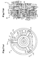
- Fig. 7(a) is a front view illustrating a power
transmission mechanism according to a second embodiment;
- Fig. 7(b) is a cross-sectional view taken along line 7b-7b
in Fig. 7(a);
- Fig. 8 is an enlarged partial cross-sectional view
illustrating rubber dumpers and a power transmission piece
according to the second embodiment;
- Fig. 9 is an enlarged cross-sectional view illustrating
a power transmission mechanism according to a third embodiment
of the present invention; and
- Fig. 10 is a cross-sectional view illustrating a power
transmission mechanism according to a fourth embodiment of the
present invention.
-
DETAILED DESCRIPTION OF THE PREFERRED EMBODIMENTS
-
A compressor C according to a first embodiment of the
present invention will now be described with reference to Figs.
1 to 6. The left end of the compressor C in Fig. 1 is defined
as the front of the compressor, and the right end is defined
as the rear of the compressor C.
-
The compressor C forms a part of a vehicular air
conditioner. As shown in Fig. 1, the compressor C includes a
cylinder block 11, a front housing member 12, a valve plate
assembly 13, and a rear housing member 14. The front housing
member 12 is secured to the front end of the cylinder block 11.
The rear housing member 14 is secured to the rear end of the
cylinder block 11 with the valve plate assembly 13 in between.
The cylinder block 11, the front housing member 12, the valve
plate assembly 13, and the rear housing member 14 form the
housing of the compressor C. The valve plate assembly 13 has
suction ports 29, suction valve flaps 30, discharge ports 31
and discharge valve flaps 32. Each set of the suction port 29,
the suction valve flap 30, the discharge port 31 and the
discharge valve flap 32 corresponds to one of the cylinder
bores 24.
-
The cylinder block 11 and the front housing member 12
define a control pressure zone, which is a crank chamber 15 in
the first embodiment, in between.
-
A rotary shaft 16 is housed in the compressor housing
and extends through the crank chamber 15. The front portion of
the rotary shaft 16 is supported by a radial bearing 12A
located in the front wall of the front housing member 12. The
rear portion of the rotary shaft 16 is supported by a radial
bearing 11A located in the cylinder block 11.
-
The front end portion of the rotary shaft 16 extends
through the front wall of the front housing member 12. A
power transmission mechanism PT is fixed to the front end of
the rotary shaft 16. The power transmission mechanism PT
includes a first rotary body, which is a pulley 17 in the
first embodiment. The front end of the rotary shaft 16 is
coupled to an external drive source, which is a vehicular
engine E in the first embodiment, by the power transmission
mechanism PT and a belt 18, which is engaged with the pulley
17.
-
A sealing member 12B is located between the front end of
the rotary shaft 16 and the front wall of the front housing
member 12. The sealing member 12B is located outward of the
front housing member 12 from the radial bearing12A in the
axial direction of the rotary shaft 16. The sealing member
12B separates the inside and outside of the compressor housing.
-
The power transmission mechanism PT and the compressor C
form a vehicular rotational apparatus.
-
A lug plate 19 is coupled to the rotary shaft 16 and is
located in the crank chamber 15. The lug plate 19 rotates
integrally with the rotary shaft 16. A drive plate, which is
a swash plate 20 in the first embodiment, is housed in the
crank chamber 15. The swash plate 20 slides along and
inclines with respect to the rotary shaft 16. The swash plate
20 is coupled to the lug plate 19 by a hinge mechanism 21.
The lug plate 19 permits the swash plate 20 to rotate
integrally with the rotary shaft 16 and to incline with
respect to the rotary shaft 16 while sliding along the
rotation axis of the rotary shaft 16.
-
A snap ring 22 is fitted about the rotary shaft 16. A
spring 23 extends between the snap ring 22 and the swash plate
20. The snap ring 22 and the spring 23 limit the minimum
inclination angle of the swash plate 20. At the minimum
inclination angle of the swash plate 20, the angle defined by
the swash plate 20 and the axis of the rotary shaft 16 is
closest to ninety degrees.
-
Cylinder bores 24 (only one is shown in Fig. 1) are
formed in the cylinder block 11. The cylinder bores 24 are
located about the rotation axis of the rotary shaft 16. A
single-headed piston 25 is housed in each cylinder bore 24 to
reciprocate inside the cylinder bore 24. The front and rear
openings of each cylinder bore 24 are closed by the associated
piston 25 and the valve plate assembly 13. A compression
chamber is defined in each cylinder bore 24. The volume of
the compression chamber changes according to the reciprocation
of the corresponding piston 25. Each piston 25 is coupled to
the peripheral porLion of the swash plate 20 by a pair of
shoes 26. When the swash plate 20 is rotated by rotation of
the rotary shaft 16, the shoes 26 convert the rotation into
reciprocation of each piston 25.
-
The cylinder block 11 (cylinder bores 24), the rotary
shaft 16, the lug plate 19, the swash plate 20, the hinge
mechanism 21, the pistons 25, and the shoes 26 form a piston
type variable displacement compression mechanism.
-
A suction pressure zone, which is a suction chamber 27
in the first embodiment, and a discharge pressure zone, which
is a discharge chamber 28 in the first embodiment, are defined
in the rear housing member 14. The front ends of the suction
chamber 27 and the discharge chamber 28 are closed by the
valve plate assembly 13. As each piston 25 moves from the top
dead center position to the bottom dead center position,
refrigerant gas is drawn into the corresponding cylinder bore
24 (compression chamber) through the corresponding suction
port 29 while flexing the suction valve flap 30 to an open
position. Low pressure refrigerant gas that is drawn into the
cylinder bore 24 is compressed to a predetermined pressure as
the piston 25 is moved from the bottom dead center position to
the top dead center position. Then, the gas is discharged to
the discharge chamber 28 through the corresponding discharge
port 31 while flexing the discharge valve flap 32 to an open
position.
-
The suction chamber 27 is connected to the discharge
chamber 28 by an external refrigerant circuit 33. The
external refrigerant circuit 33 includes a condenser 34, a
decompression device, which is an expansion valve 35 in the
first embodiment, and an evaporator 36. The opening degree of
the expansion valve 35 is feedback-controlled based on the
temperature and pressure of refrigerant detected by a heat
sensitive tube (not shown) at the outlet, or downstream, of
the evaporator 36. The expansion valve 35 supplies
refrigerant, the amount of which corresponds to the thermal
load (cooling load), to the evaporator 36 to regulate the flow
rate in the external refrigerant circuit 33.
-
A connecting pipe 37 for refrigerant gas is located at a
downstream portion of the external refrigerant circuit 33 and
connects the outlet of the evaporator 36 to the suction
chamber 27 of the compressor C. Another connecting pipe 38
for refrigerant gas is located at an upstream portion of the
external refrigerant circuit 33 and connects the discharge
chamber 28 of the compressor C to the condenser 34. The
compressor C draws in refrigerant gas introduced into the
suction chamber 27 from the downstream portion of the external
refrigerant circuit 33 and compresses the refrigerant gas.
Then, the compressor C discharges the compressed gas to the
discharge chamber 28, which is connected to the upstream
portion of the external refrigerant circuit 33.
-
The compressor C and the external refrigerant circuit 33
constitute a refrigeration circuit (or refrigerant circuit) of
the vehicular air-conditioner.
-
The cylinder block 11 has a shaft bore 39, which
accommodates the rear end of the rotary shaft 16. A shaft
passage 40 is formed in the rotary shaft 16 to connect the
front portion of the crank chamber 15 with the shaft bore 39.
A communication passage 41 is formed in the valve plate
assembly 13 to connect the suction chamber 27 with the shaft
bore 39. The shaft bore 39, the shaft passage 40, and the
communication passage 41 constitutes a bleed passage, which
connects the crank chamber 15 with the suction chamber 27.
-
A supply passage 42 is formed in the housing to connect
the discharge chamber 28 with the crank chamber 15. A control
valve 43 is located in the supply passage 42 to regulate the
opening degree of the supply passage 42.
-
The opening of the control valve 43 is adjusted to
control the flow rate of highly pressurized gas supplied to
the crank chamber 15 through the supply passage 42. The
pressure in the crank chamber 15 (crank chamber pressure Pc)
is determined by the ratio of the gas supplied to the crank
chamber 15 through the supply passage 42 and the flow rate of
refrigerant gas conducted out from the crank chamber 15
through the bleed passage. As the crank chamber pressure Pc
varies, the difference between the crank chamber pressure Pc
and the pressure in the compression chambers varies, which
changes the inclination angle of the swash plate 20.
Accordingly, the stroke of each piston 25, or the amount of
refrigerant discharged during one rotation of the rotary shaft
16, is varied.
-
The compressor C according to the first embodiment is
formed such that the amount of refrigerant discharged during
one rotation of the rotary shaft 16 is substantially zero when
the inclination angle of the swash plate 20 is minimum.
-
The greater the flow rate of the refrigerant Q flowing
in the refrigerant circuit is, the greater the pressure loss
per unit length of the circuit or piping is. That is, the
pressure loss (pressure difference) between first and second
pressure monitoring points P1, P2 has a positive correlation
with the flow rate of the refrigerant Q in the refrigerant
circuit. Detecting the pressure difference between the first
and second pressure monitoring points P1, P2 (PdH-PdL =
pressure difference ΔPX) permits the flow rate of refrigerant
Q in the refrigerant circuit to be indirectly detected.
-
In the first embodiment, the first pressure monitoring
point P1, which functions as a high pressure monitoring point,
is located in the discharge chamber 28, the pressure of which
is equal to that of the most upstream section of the
connecting pipe 38. The second pressure monitoring point P2,
which functions as a low pressure monitoring point, is located
midway along the connecting pipe 38 at a position separated
from the first pressure monitoring point P1 by a predetermined
distance. The pressure PdH at the first pressure monitoring
point P1 is applied to the control valve 43 through a first
pressure introduction passage 44 (see Fig. 2). The pressure
PdL at the second pressure monitoring point P2 is applied to
the control valve 43 through a second pressure introduction
passage 45 (see Fig. 2).
-
A throttle 46 may be formed in the connecting pipe 38
between the first and second pressure monitoring points P1, P2
to increase the pressure difference ΔPX. The throttle 46
increases the pressure difference ΔPX between the first and
second pressure monitoring points P1, P2 although the first
and second pressure monitoring points P1, P2 are not separated
by a large amount. Providing the throttle 46 between the
first and second pressure monitoring points P1, P2 permits the
second pressure monitoring point P2 to be located close to the
compressor C. This shortens the second pressure introduction
passage 45 between the second pressure monitoring point P2 and
the control valve 43. The pressure PdL at the second pressure
monitoring point P2 is set sufficiently higher than the crank
chamber pressure Pc although the pressure PdL is decreased
with respect to the pressure PdH by the throttle 46.
-
As shown in Fig. 2, the control valve 43 has a valve
housing 47. The valve housing 47 defines a valve chamber 48,
a communication passage 49, and a pressure sensing chamber 50.
A transmission rod 51 extends through the valve chamber 48 and
the communication passage 49. The transmission rod 51 moves
in the axial direction, or in the vertical direction as viewed
in Fig. 2.
-
The communication passage 49 is disconnected from the
pressure sensing chamber 50 by the upper portion of the
transmission rod 51, which is fitted in the communication
passage 49. The valve chamber 48 is connected to the
discharge chamber 28 through an upstream section of the supply
passage 42. The communication passage 49 is connected to the
crank chamber 15 by a downstream section of the supply passage
42. The valve chamber 48 and the communication passage 49
form a part of the supply passage 42.
-
A valve body 52 is formed at the middle portion of the
transmission rod 51 and is located in the valve chamber 48. A
step defined between the valve chamber 48 and the
communication passage 49 functions as a valve seat 53. The
communication passage 49 serves as a valve hole. The
transmission rod 51 shown in Fig. 2 is located at the
lowermost position where the opening degree of the
communication passage 49 is the greatest. When the
transmission rod 51 is moved from the lowermost position to
the uppermost position, at which the valve body 52 contacts
the valve seat 53, the communication passage 49 is
disconnected from the valve chamber 48. That is, the valve
body 52 of the transmission rod 51 is a valve body that
controls the opening degree of the supply passage 42.
-
A pressure sensing member, which is a bellows 54 in the
first embodiment, is located in the pressure sensing chamber
50. The upper end of the bellows 54 is fixed to the valve
housing 47.The lower end of the bellows 54 receives the upper
end of the transmission rod 51. The bellows 54 divides the
pressure sensing chamber 50 into a first pressure chamber 55,
which is the interior of the bellows 54, and a second pressure
chamber 56, which is the exterior of the bellows 54. The
first pressure chamber 55 is connected to the first pressure
monitoring point P1 by the first pressure introduction passage
44. The second pressure chamber 56 is connected to the second
pressure monitoring point P2 by the second pressure
introduction passage 45. Therefore, the first pressure
chamber 55 is exposed to the pressure PdH monitored at the
first pressure monitoring point P1, and the second pressure
chamber 56 is exposed to the pressure PdL monitored at the
second pressure monitoring point P2. The bellows 54 and the
pressure sensing chamber 50 form a pressure sensing mechanism.
-
A target pressure difference changing means, which is an
electromagnetic actuator 57 in the first embodiment, is
located at the lower portion of the valve housing 47. The
electromagnetic actuator 57 includes a cup-shaped cylinder 58,
which is arranged coaxial to the valve housing 47. A
stationary iron core 59 is fitted in the upper opening of the
cylinder 58 and is secured to the cylinder 58. The stationary
iron core 59 defines a plunger chamber 60 at the lowermost
portion in the cylinder 58.
-
A movable iron core 61 is located in the plunger chamber
60. The movable iron core 61 slides along the plunger chamber
60 in the axial direction. An axially extending guide hole 62
is formed in the central portion of the stationary iron core
59. The lower end of the transmission rod 51 is located in
the guide hole 62 to move axially. The lower end of the
transmission rod 51 abuts against the movable iron core 61 in
the plunger chamber 60.
-
A coil spring, which is a spring 63 in the first
embodiment, is located between the inner bottom surface of the
cylinder 58 and the movable iron core 61 in the plunger
chamber 60. The spring 63 urges the movable iron core 61
toward the transmission rod 51. The transmission rod 51 is
urged toward the movable iron core 61 by the elasticity of the
bellows 54. Therefore, the movable iron core 61 and the
transmission rod 51 integrally move vertically. Hereinafter,
urging force based on the elasticity of the bellows 54 is
referred to as the spring force of the bellows. The spring
force of the bellows 54 is greater than the force of the
spring 63.
-
A coil 64 is wound about the stationary iron core 59 and
the movable iron core 61 on the outer circumference of the
cylinder 58. Power is supplied to the coil 64 from a battery
via a drive circuit (not shown) based on commands from a
controller, which is not shown.
-
The coil 64 generates an electromagnetic force
(electromagnetic attracting force) between the movable iron
core 61 and the stationary iron core 59 in accordance with the
value of current supply to the coil 64. Upward force is
applied to the transmission rod 51 via the movable iron core
61 in accordance with the electromagnetic force. In the first
embodiment, current supplied to the coil 64 is varied by
controlling the applied voltage. The applied voltage is
controlled by pulse-width modulation, or duty control.
-
According to the control valve 43, the position of the
transmission rod 51 (valve body 52), or the opening degree, is
determined in the following manner.
-
When no current is supplied to the coil 64, or when the
duty ratio is zero percent, the downward force generated by
the spring force of the bellows 54 dominantly acts on the
transmission rod 51. Thus, the transmission rod 51 is placed
at its lowermost position, and the communication passage 49 is
fully opened. Therefore, the crank chamber pressure Pc is the
maximum that is possible under the given conditions. The
pressure difference between the crank chamber pressure Pc and
the pressure in the compression chambers thus becomes large.
As a result, the inclination angle of the swash plate 20 is
minimized and the amount of refrigerant discharged during one
rotation of the rotary shaft 16 is also minimized.
-
When a current of the minimum duty ratio or more within
the variation range of the duty ratio is supplied to the coil
64, the resultant of the upward force of the spring 63 and the
upward electromagnetic force exceeds the downward force
generated by the spring force of the bellows 54 so that the
transmission rod 51 is moved upward. In this state, the
resultant of the upward force of the spring 63 and the upward
electromagnetic force acts against the resultant of the force
based on the pressure difference ΔPX and the downward force
generated by the spring force of the bellows 54. The position
of the valve body 52 of the transmission rod 51 relative to
the valve seat 53 is determined such that upward and downward
forces are balanced.
-
For example, if the flow rate of refrigerant in the
refrigerant circuit is decreased, the downward force based on
the pressure difference ΔPX, which acts on the transmission
rod 51, decreases. Therefore, the transmission rod 51 (valve
body 52) moves upward to decrease the opening degree of the
communication passage 49, which lowers the crank chamber
pressure Pc. Accordingly, the inclination angle of the swash
plate 20 is increased, and the displacement of the compressor
C is increased. The increase in the displacement of the
compressor C increases the flow rate of refrigerant in the
refrigerant circuit, which increases the pressure difference
ΔPX.
-
In contrast, when the flow rate of refrigerant in the
refrigerant circuit is increased, the downward force based on
the pressure difference ΔPX increases. Therefore, the
transmission rod 51 (valve body 52) moves downward to increase
the opening degree of the communication passage 49, which
increases the crank chamber pressure Pc. Accordingly, the
inclination angle of the swash plate 20 is decreased, and the
displacement of the compressor C is decreased. The decrease in
the displacement of the compressor C decreases the flow rate
of refrigerant in the refrigerant circuit, which decreases the
pressure difference ΔPX.
-
When the duty ratio of the electric current supplied to
the coil 64 is increased to increase the upward
electromagnetic force, the pressure difference ΔPX cannot
balance the forces acting on the transmission rod 51.
Therefore, the transmission rod 51 (the valve body 52) moves
upward and decreases the opening degree of the communication
passage 49. As a result, the displacement of the compressor C
is increased. Thus, the flow rate of refrigerant in the
refrigerant circuit increases, which increases the pressure
difference ΔPX.
-
When the duty ratio of the electric current supplied to
the coil 64 is decreased to decrease the upward
electromagnetic force, the pressure difference ΔPX cannot
balance the forces acting on the transmission rod 51.
Therefore, the transmission rod 51 (the valve body 52) moves
downward and increases the opening degree of the communication
passage 49. As a result, the displacement of the compressor C
is decreased. Thus, the flow rate of refrigerant in the
refrigerant circuit decreases, which decreases the pressure
difference ΔPX.
-
As described above, the target value of the pressure
difference ΔPX is determined by the duty ratio of current
supplied to the coil 64. The control valve 43 automatically
determines the position of the transmission rod 51 (the valve
body 52) according to changes of the pressure difference ΔPX
to maintain the target value of the pressure difference ΔPX.
The target value of the pressure difference ΔPX is externally
controlled by adjusting the duty ratio of current supplied to
the coil 64.
-
As shown in Figs. 1 and 4, the pulley 17 has an upstream
pulley 17A and a downstream pulley 17B.
-
The upstream pulley 17A includes a first outer cylinder
17D, a first inner cylinder 17E, and a first disk 17F. The
first outer cylinder 17D has a power transmission portion 17C
about which the belt 18 is wound. The first disk 17F is
integrally formed with the first outer cylinder 17D and the
first inner cylinder 17E to connect them with each other. The
power transmission portion 17C is formed on the outer
circumferential portion of the first outer cylinder 17D.
-
Shutoff mechanism (breakable members), which are
substantially columnar power transmission pins 17G (only two
are shown) in the first embodiment, are secured to the front
surface of the first outer cylinder 17D at equal angular
intervals in the circumferential direction of the first outer
cylinder 17D . The power transmission pins 17G are fit in
holes formed in the front surface of the first outer cylinder
17D. The power transmission pins 17G project forward from the
first outer cylinder 17D and are substantially parallel to the
axis of the rotary shaft 16.
-
The power transmission pins 17G are made of sintered
metal. The fatigue ratio σW/σB of the sintered metal is
about 0.5. The sign σW represents the fatigue limit and the
sign σB represents the tensile strength.
-
The downstream pulley 17B includes a second inner
cylinder 17H, a second disk 17J, and a second outer cylinder
17K. The second disk 17J is formed integrally with the second
inner cylinder 17H and extends radially outward from the front
end of the second inner cylinder 17H. The second outer
cylinder 17K is integrally formed with the second disk 17J and
extends rearward from the outer circumferential portion of the
second disk 17J.
-
Shock absorbers, which are rubber dumpers 17L in the
first embodiment, are secured to positions corresponding to
the power transmission pins 17G at the rear surface of the
second outer cylinder 17K of the downstream pulley 17B. Each
rubber dumper 17L is accommodated in one of bores formed in
the rear surface of the second outer cylinder 17K. Each
rubber dumper 17L is cup-shaped and receives the corresponding
power transmission pin 17G.
-
Therefore, in the pulley 17 of the first embodiment,
power transmitted from the engine E to the upstream pulley 17A
by the belt 18 is transmitted to the downstream pulley 17B by
the power transmission pins 17G and the rubber dumpers
17L.That is, the power transmission pins 17G and the rubber
dumpers 17L are located in a power transmission path between
the upstream pulley 17A and the downstream pulley 17B.
-
In the first embodiment, the upstream pulley 17A, the
downstream pulley 17B, the power transmission pins 17G, and
the rubber dumpers 17L constitute the pulley 17. The pulley
17 has an inner space surrounded by the upstream pulley 17A,
the downstream pulley 17B, and the like.
-
A substantially cylindrical hub 65 is fixed to the front
end of the rotary shaft 16. A pulley one-way clutch 66 is
located between the hub 65 and the second inner cylinder 17H
of the downstream pulley 17B. The pulley one-way clutch 66 is
a first one-way clutch located in a power transmission path
between the pulley 17 and the rotary shaft 16.
-
The pulley one-way clutch 66 is constituted by a clutch
portion 67 and a bearing portion 68 (see Fig. 4). The clutch
portion 67 and the bearing portion 68 are integrally formed
with each other and arranged next to each other in the axial
direction of the rotary shaft 16.
-
The pulley one-way clutch 66 includes an outer ring 69,
which is secured to the inner circumferential surface of the
second inner cylinder 17H, and an inner ring 70, which is
secured to the outer circumferential surface of the hub 65 and
surrounded by the outer ring 69. The outer ring 69 and the
inner ring 70 rotate relative to each other by rotating bodies,
which are balls 71 in the first embodiment. The balls 71 are
arranged circumferentially in line between the outer ring 69
and the inner ring 70.
-
As shown in Fig. 3, recesses 72 are formed at equal
angular intervals around the rotary shaft 16 in the inner
circumferential portion of the outer ring 69.
-
A power transmission surface 73 is formed at the
trailing end of each recess 72. A roller 74 is accommodated
in each recess 72 parallel to the rotary shaft 16. Each
roller 74 is movable from the position where the roller 74 is
engaged with the power transmission surface 73 as shown in Fig.
3 (a) to the position where the roller 74 is disengaged from
the power transmission surface 73 as shown in Fig. 3 (b).
-
A spring seat 75 is located at the leading end of each
recess 72, or the end of each recess 72 that is opposite to
the power transmission surface 73. A spring 76 is arranged
between each spring seat 75 and the corresponding roller 74 to
urge the roller 74 toward the position where the roller 74 is
engaged with the power transmission surface 73.
-
As shown in Fig. 3(a), when the outer ring 69 rotates in
the direction indicated by an arrow by power transmitted from
the engine E with the pulley 17, each roller 74 moves toward
the corresponding power transmission surface 73 by the force
of the spring 76. Then, the roller 74 is engaged with the
power transmission surface 73.The inner ring 70 is rotated in
the same direction as the outer ring 69 by the friction
between the roller 74 and the outer circumferential surface of
the inner ring 70 and the friction between the roller 74 and
the power transmission surface 73.
-
Therefore, when the vehicle engine E is running, power
of the engine E is transmitted to the rotary shaft 16 by the
pulley 17, the clutch portion 67, and the hub 65. Thus, the
rotary shaft 16 is always driven when the engine E is running.
-
As shown in Fig. 3(b), if the inner ring 70 is rotated
in the direction indicated by an arrow when the engine E (or
the pulley 17) is stopped, the roller 74 separates from the
power transmission surface 73 against the force of the spring
76. Thus, the inner ring 70 runs idle with respect to the
outer ring 69.
-
As shown in Figs. 1 and 4, an elecLric motor 77 is
located in the inner space of the pulley 17. A cylindrical
shaft support 12C projects from the front wall of the front
housing member 12 and surrounds the front end of the rotary
shaft 16. A brush device, which constitutes part of the
electric motor 77, includes brush units 78. The brush units
78 are located on the outer circumference of the cylindrical
shaft support 12C. Each brush unit 78 is accommodated in one
of grooves (or recesses) 12D formed on the outer circumference
of the cylindrical shaft support 12C.
-
As shown in Fig. 6, each brush unit 78 includes a
rectangular brush 78A and a resin brush case 78B, which has a
substantially rectangular shape with a bottom. Each brush
case 78B accommodates one of the brushes 78A, which slides
with respect to the brush case 78B. In the first embodiment,
the brushes 78A slide in the axial direction of the rotary
shaft 16.
-
A pigtail 78C is connected to the rear end (right side
as viewed in Fig. 6, or opposite to the side that contacts a
commutator 82C, which will be described later) of each brush
78A. One end of the pigtail 78C is inserted in and connected
to a recess formed on the rear end of the brush 78A. The
other end of the pigtail 78C is connected to a metal plate 78D
located at the rear wall (right side as viewed in Fig. 6) of
the brush case 78B.
-
The brush 78A, the brush case 78B, the pigtail 78C, and
the metal plate 7BD constitute each brush unit 78.
-
Each metal plate 78D is connected to one of the ends of
a lead wire 86. The end of the lead wire 86 is molded in the
rear wall of the brush case 78B. Therefore, the pigtail 78C,
the metal plate 78D, and the lead wire 86 constitute an
electric line. The electric line is located at the end of the
brush 78A opposite to the end facing the commutator 82C.
-
A spring 78F is located between each brush 78A and the
corresponding metal plate 78D. The spring 78F urges the brush
78A toward the commutator 82C.
-
A stator fixing member 80 for fixing a stator 79 of the
electric motor 77 to the housing has a cylindrical support
portion 80A. The cylindrical support portion 80A is fitted to
the outer circumference of the shaft support 12C, or about the
brush units 78 as shown in Figs. 1, 4, and 5. A pulley
bearing 81 is located between the outer circumferential
surface of the cylindrical support portion 80A and the inner
circumferential surface of the first inner cylinder 17E of the
upstream pulley 17A. The pulley bearing 81 supports the
pulley 17 such that the pulley 17 rotates with respect to the
housing. That is, the brush units 78 are located radially
outward of the shaft support 12C and radially inward of the
pulley bearing 81. The pulley bearing 81 is located to
overlap the brush units 78 in the axial direction of the
rotary shaft 16.
-
The stator fixing member 80 includes a substantially
cylindrical stator holder 80B, which holds the stator 79, and
a connecting portion 80C, which connects the stator holder 80B
and the cylindrical support portion 80A. Part of rear side of
the stator holder 80B, the connecting portion 80C, and the
cylindrical support portion 80A are located inside the power
transmission portion 17C. The stator 79 is formed of a
permanent magnet and attached to the inner circumferential
surface of the stator holder 80B.
-
A second rotary body, which is a rotor 82 in the first
embodiment, is located inward of the stator holder 80B (more
specifically, inward of the stator 79) to face the stator 79.
The rotor 82 includes a rotor iron core 82A and a coil 82B,
which'is wound about the periphery of the rotor iron core 82A.
The commutator 82C is located at the rear surface of the inner
portion of the rotor iron core 82A to face the brushes 78A.
The commutator 82C is constituted by a plate-like conductors,
which are arranged radially and perpendicular to the axial
direction of the rotary shaft 16.
-
Electric current is supplied to the coil 82B by the
brushes 78A and the commutator 82C.The electric motor 77
produce rotational force of the rotor 82 by interaction
between the magnetic force of the stator 79 and the magnetic
force genera Led on the rotor 82 in accordance with the current
supply.
-
The lead wire 86 of each brush unit 78 (see Fig. 6) is
connected to a drive circuit, which is not shown. The drive
circuit is connected to a battery, which is not shown, and
controls to supply or stop supplying current to the brushes
78A based on commands from a controller (not shown).
-
The brush units 78, the stator 79, the stator fixing
member 80, and the rotor 82 constitute the electric motor 77.
-
A second one-way clutch, which is a motor one-way clutch
83 in the first embodiment, is located in a power transmission
path between the rotor 82 and the rotary shaft 16. The
structure of the motor one-way clutch 83 is the same as the
pulley one-way clutch 66. Therefore, like or the same
reference numerals are given to those components that are like
or the same as the corresponding components in the pulley one-way
clutch 66 and detailed explanations are omitted. In the
motor one-way clutch B3, the outer ring 69 is secured to the
inner circumferential surface of the rotor iron core 82A and
the inner ring 70 is secured to the outer circumferential
surface of the rotary shaft 16. Part of the motor one-way
clutch 83 is located to overlap the brush units 78 in the
axial direction of the rotary shaft 16.
-
The pulley 17, the pulley bearing 81, the hub 65, the
pulley one-way clutch 66, the motor one-way clutch 83, and the
electric motor 77 constitute the power transmission mechanism
PT.
-
In the first embodiment, when the vehicular engine E is
running, the power is always transmitted to the rotary shaft
16 by the pulley 17 and the pulley one-way clutch 66. If an
air-conditioning is required when the vehicular engine E is
stopped, the electric motor 77 is actuated and power is
transmitted to the rotary shaft 16 by the motor one-way clutch
83.
-
The controller controls the drive circuit such that
electric current is not supplied to the brushes 78A when the
vehicular engine E is running. When the vehicular engine E is
running, power is transmitted from the outer ring 69 of the
pulley one-way clutch 66 to the inner ring 70 of the pulley
one-way clutch 66. The power of the vehicular engine E is
thus transmitted to the rotary shaft 16. At this time, the
inner ring 70 of the motor one-way clutch 83 integrally
rotates with the rotary shaft 16. However, the inner ring 70
of the motor one-way clutch 83 runs idle with respect to the
outer ring 69 of the motor one-way clutch 83. Thus, power of
the vehicular engine E is hardly used for rotating the rotor
82.
-
For example, to rotate the rotor 82 by the rotational
force of the rotary shaft 16, an amount of torque that
corresponds to the cogging torque caused by magnetic force
generated by the stator 79 is required. However, in the first
embodiment, when the motor one-way clutch 83 runs idle, the
torque transmitted from the inner ring 70 to the outer ring 69
is smaller than the cogging torque. Therefore, when current
is not supplied to the brushes 78A, the rotor 82 is hardly
rotated although the rotary shaft 16 is rotated.
-
If an air-conditioning is required when the vehicular
engine E is stopped, the drive circuit supplies current to the
brushes 78A to drive the electric motor 77 based on commands
from the controller. The rotational force of the rotor 82
generated by current supply is transmitted from the outer ring
69 of the motor one-way clutch to the inner ring 70 of the
motor one-way clutch 83. Therefore, power of the electric
motor 77 is transmitted to the rotary shaft 16. This enables
the air-conditioning of a passenger compartment while the
vehicular engine E is stopped.
-
At this time, the inner ring 70 of the pulley one-way
clutch 66 integrally rotates with the hub 65 and the rotary
shaft 16. However, the inner ring 70 runs idle with respect
to the outer ring 69 of the pulley one-way clutch 66. Thus,
power of the electric motor 77 is hardly transmitted to the
pulley 17.
-
Power transmitted from the engine E to the upstream
pulley 17A is transmitted to the downstream pulley 17B through
the rubber dampers 17L and the power transmission pins 17G.
-
The rubber dumpers 17L located in the power transmission
path between the upstream pulley 17A and the downstream pulley
17B absorb the misalignment between the rotation axes of the
upstream pulley 17A and the downstream pulley 17B. That is,
the deformation of the rubber dumpers 17L reduces stress
applied to the bearings, such as the radial bearing 12A, the
bearing portion 68 of the pulley one-way clutch 66, and the
pulley bearing 81, duc to the misalignment of the rotation
axes. The rubber dumpers 17L dampen the rotation-vibration
(torque fluctuation) of the rotary shaft 16 caused by the
compression reaction force at the compression mechanism and
prevent the rotation-vibration from being transmitted from the
downstream pulley 17B to the upstream pulley 17A.
-
The pulley one-way clutch 66 transmits power from the
pulley 17 to the hub 65 but hardly transmits power from the
hub 65 to the pulley 17. Therefore, the rotation-vibration is
not transmitted from the hub 65 to the pulley 17.
-
As long as the magnitude of the transmission torque
between the upstream pulley 17A and the downstream pulley 17B
does not adversely affect the engine E (within the
transmission torque in a normal power transmission state),
power is transmitted from the engine E to the rotary shaft 16.
-
However, if there is an abnormality in the compressor C,
for example, if the compressor C is locked, and the
transmission torque is excessive, the power transmission pins
17G are broken by excessive load. That is, power is prevented
from being transmitted from the upstream pulley 17A to the
downstream pulley 17B. This prevents the engine E from being
adversely affected by the excessive torque.
-
The first embodiment has the following advantages.
- (1) Part of the electric motor 77 is located inside the
power transmission portion 17C. In other words, at least part
of the electric motor 77 overlaps the power transmission
portion 17C in the axial direction of the rotary shaft 16 and
is located radially inward of the power transmission portion
17C. Therefore, as compared to a case in which the elecLric
motor is not located inside the power transmission portion,
the vehicular rotational apparatus is easily minimized in the
axial direction of the rotary shaft.
- (2) The pulley one-way clutch 66 is located in the power
transmission path between the pulley 17 and the rotary shaft
16, and the motor one-way clutch 83 is located in the power
transmission path between the electric motor 77 and the rotary
shaft 16. Therefore, one of the power transmission paths is
connected while the other is disconnected. In this case, the
rotary shaft 16 is rotated by power of the vehicular engine E
without rotating the rotor 82 of the electric motor 77. To
rotate the rotor 82 by the rotation of the rotary shaft 16,
the rotary shaft 16 needs to be rotated by a torque that
corresponds to the cogging torque caused by the stator 79.
This applies additional rotary load to the rotary shaft 16.
With the structure of the first embodiment, the rotary load is
decreased by connecting the pulley one-way clutch 66 and
disconnecting the motor one-way clutch 83.
- (3) The electric motor 77 supplies current to the rotor
82 using the brush units 78. If a brushless motor, which
controls current supply to a stator based on rotational
position data of a rotor detected by a sensor, is applied as
an electric motor, means for detecting the rotational position
of the rotor is required. However, in the first embodiment,
as compared to the above case, the detecting means is not
required, which simplifies the structure of the electric motor.
- (4) The pulley bearing 81 is located to overlap the
brush units 78 in the axial direction of the rotary shaft
16.In this case, the size of the vehicular rotational
apparatus is easily reduced in the axial direction of the
rotary shaft 16 as compared to a structure in which the pulley
bearing 81 does not overlap the brush units 78.
- (5) Part of the motor one-way clutch 83 is located to
overlap the brush units 78 in the axial direction of the
rotary shaft 16. In this case, the size of the vehicular
rotational apparatus is easily reduced in the axial direction
of the rotary shaft 16 as compared to a structure in which the
motor one way-clutch 83 does not overlap the brush units 78.
- (6) The brush units 78 are located on the outer
circumference of the shaft support 12C and inward of the
pulley bearing 81. The brushes 78A slide in the axial
direction of the rotary shaft 16. In this case, for example,
the size of the pulley bearing 81 is reduced in the radial
direction as compared to a case in which the brushes 78A are
located to slide in the radial direction of the rotary shaft
16. Reducing the size of the pulley bearing 81 reduces the
peripheral velocity of the rotary member of the pulley bearing
81. This extends the life of the pulley bearing 81.
- (7) The brushes 78A are located to slide in the axial
direction of the rotary shaft 16. Therefore, the commutator
82C can be formed into a plate arranged perpendicular to the
axial direction. As a result, the size of the electric motor
77 is easily reduced in the axial direction.
- (8) Each brush unit 78 is accommodated in one of the
grooves 12D formed on the outer circumference of the
cylindrical shaft support 12C. In this case, for example, the
size of the pulley bearing 81 is reduced in the radial
direction as compared to a case in which the brush units 78
are located on the outer circumferential surface of the shaft
support 12C on which grooves 12D are not formed. Also,
spacers for securing the pulley bearing 81 to the shaft
support 12C need not be located in the spaces between the
brush units 78 in the circumferential direction.
- (9) Each electric line is located at the end of one of
the brushes 78A opposite to the end facing the commutator 82C.
In this case, for example, the spaces between the brushes 78A
in the circumferential direction are reduced as compared to a
case in which each electric line is connected to the side of
the corresponding brush 78A in the circumferential direction
of the rotary shaft 16. In other words, the circumferential
width of each brush 78A can be increased. As a result, a
large contact surface between the brushes 78A and the
commutator 82C is easily obtained, which facilitates obtaining
a certain amount of current transmitted between the brushes
and the commutator 82C, or the output of the electric motor.
Also, with the structure of the first embodiment, in which the
brushes 78A are accommodated in the grooves 12D, it is not
required to prepare a space for accommodating each electric
line on the side of the corresponding brush 78A in the
circumferential direction. Thus, the strength of the shaft
support 12C is easily prevented from being reduced.
- (10) The power transmission pins 17G prevent excessive
load from being applied to the vehicular engine E, even when
the compressor C causes an abnormality, or the compressor C is
locked.
- (11) The power transmission pins 17G are made of
sintered metal. Since the ductility of the sintered metal is
relatively low, the threshold level of the transmission torque
at which the power transmission pins 17G are broken is easily
determined.
- (12) The rubber dampers 17L are located in the power
transmission path between the upstream pulley 17A and the
downstream pulley 17B. In this case, the misalignment of the
rotation axes between the upstream pulley 17A and the
downstream pulley 17B caused by, for example, a manufacturing
tolerance is absorbed by the rubber dampers 17L. Therefore,
the deformation of the rubber dumpers 17L reduces stress
applied to the bearings, such as the radial bearing 12A, the
bearing portion 68 of the pulley one-way clutch 66, and the
pulley bearing 81, due to the misalignment of the rotation
axes. As a result, the durability of the vehicular rotational
apparatus is improved.
- (13) The rubber dampers 17L reduce the rotation
vibration (torque fluctuation) transmitted from the downstream
pulley 17B to the upstream pulley 17A. As a result, vibration
between the vehicular engine E and the rotary shaft 16 caused
by fluctuation of the transmission torque is suppressed.
- (14) The amount of refrigerant discharged during one
rotation of the rotary shaft 16 can be substantially zero. In
this case, the amount of refrigerant discharged from the
compression mechanism can be substantially zero even when the
rotary shaft 16 is being rotated. As a result, when air-conditioning
is unnecessary, the load required to drive the
rotary shaft 16 is minimized (to zero if possible).
- (15) The displacement (flow rate of refrigerant) of the
compressor C, which greatly affects the load torque of the
compressor C, is directly controlled from the outside. Also,
for example, the flow rate of refrigerant is controlled to be
less than or equal to a predetermined amount with high
accuracy and quick response without using, for example, a flow
rate sensor.
A second embodiment of the present invention will now be
described. The second embodiment is the same as the first
embodiment except for the structure of the power transmission
mechanism PT. Mainly, the differences from the first
embodiment will be discussed below, and same or like reference
numerals are given to parts that are the same as or like
corresponding parts of the first embodiment. Fig. 7(a) is a front view illustrating the power
transmission mechanism PT. Fig. 7(b) is a cross-sectional
view taken along line 7b-7b in Fig. 7(a). Part of the
compressor C is also shown in Fig. 7(b).In the second embodiment, a motor housing 84 is secured
to the front end of the front housing member 12. The motor
housing 84, the cylinder block 11, the front housing member 12,
the valve plate assembly 13, and the rear housing member 14
form the housing of the compressor C.A shaft support 84A projects from the front wall of the
motor housing 84 to surround the front end of the rotary shaft
16. The upstream pulley 17A of the pulley 17 according to the
second embodiment is rotatably supported by the outer
circumferential surface of the shaft support 84A with a pulley
bearing 85. In Fig. 7(a), the pulley bearing 85 is not shown.The upstream pulley 17A of the second embodiment
includes an annular main body 17M, which is fitted about the
outer ring of the pulley bearing 85, and the power
transmission portion 17C, which is located at the outer
circumference of the main body 17M.The downstream pulley 17B, which forms a part of the
pulley 17 of the second embodiment, is secured to the outer
ring 69 of the pulley one-way clutch 66. The downstream
pulley 17B includes a cylindrical portion 17N, which is fitted
about the outer ring 69, arms 17P (three in the second
embodiment) (shutoff mechanism), which radially project
outward from the outer circumferential surface of the
cylindrical portion 17N, and power transmission pieces 17Q,
which project rearward from the distal end of the arms 17P.
The down stream pulley 17B according to the second embodiment
is integrally made of sintered metal that is the same as that
used for the power transmission pins 17G of the first
embodiment.Each arm 17P of the downstream pulley 17B is located at
equal angular intervals in the circumferential direction of
the pulley 17. Accommodating bores 17R are formed in the main
body 17M at positions facing the power transmission pieces 17Q.
A rear portion of each power transmission piece 17Q is
inserted into one of the accommodating bores 17R.As shown in Figs. 7(a) and 8, shock absorbers, which are
rubber dumpers 17S in the second embodiment, are press fitted
in both sides (in the circumferential direction of the pulley
17) of each power transmission piece 17Q in the corresponding
accommodating bore 17R.With this structure, power transmitted
from the engine E to the upstream pulley 17A is transmitted to
the downstream pulley 17B via the rubber dumpers 17S.The
rubber dumpers 17S dampen torque fluctuation transmitted from
the downstream pulley 17B to the upstream pulley 17A. Further,
the deformation of the rubber dumpers 17S reduces stress
applied to the bearings, such as the radial bearing 12A, the
bearing portion 68 of the pulley one-way clutch 66, and the
pulley bearing 85, due to the misalignment of the rotary axes
of the upstream pulley 17A and the downstream pulley 17B.In the second embodiment, if there is an abnormality in
the compressor C, and the transmission torque between the
upstream pulley 17A and the downstream pulley 17B is excessive,
the arms 17P are broken by excessive load. That is, the power
is prevented from being transmitted from the upstream pulley
17A to the downstream pulley 17B, which prevents the engine E
from being adversely affected by excessive torque transmission.As shown in Fig. 7(b), a motor chamber 84B is defined by
the front wall of the front housing member 12 and the motor
housing 84. In the second embodiment, the electric motor 77
is located in the motor chamber 84B.The rotor iron core 82A of the electric motor 77
includes a cylindrical portion 82D, which is fitted about the
outer ring 69 of the motor one-way clutch 83, and a coil
holder 82E, which extends radially outward from the rear
portion of the cylindrical portion 82D. The coil 82B is wound
about the coil holder 82E.In the second embodiment, the stator 79 is secured to
the inner circumferential surface of the motor housing 84 at a
position opposite to the coil 82B and the coil holder 82E.
Each brush unit 78 is accommodated in one of grooves
formed at the rear portion of the shaft support 84A. The
brush 78A of each brush unit 78 slides in the axial direction
of the rotary shaft 16. The brushes 78A contact the
commutator 82C located on the front surface of the rotor 82
between the cylindrical portion 82D and the coil holder 82E.
Part of the front side of the rotor 82 and the stator 79, and
the brush units78 are located inside the power transmission
portion 17C.Part of the pulley one-way clutch 66 and the motor one-way
clutch 83 are located to overlap the pulley bearing 85 in
the axial direction of the rotary shaft 16. Further, part of
the pulley bearing 85 and part of the motor one-way clutch 83
are located to overlap the brush units 78 in the axial
direction of the rotary shaft 16.In addition to the advantages (1) to (5), (7), and (9)
to (15), the second embodiment has the following advantages. - (16) The pulley one-way clutch 66 and the motor one-way
clutch 83 are located to overlap the pulley bearing 85 in the
axial direction of the rotary shaft 16. In this case, the
size of the vehicular rotational apparatus is reduced in the
axial direction of the rotary shaft 16 as compared to a
structure in which at least one of the pulley one-way clutch
66 and the motor one-way clutch 83 does not overlap the pulley
bearing 85 in the axial direction.
- (17) The electric motor 77 is accommodated close to the
housing of the compressor C. In this case, the size of the
pulley is reduced and the moment of inertia is easily reduced
as compared to the structure of the first embodiment, in which
the electric motor is located inside the pulley. As a result,
the rotational response of the pulley 17 is easily improved.
A third embodiment of the present invention will now be
described. The third embodiment is the same as the second
embodiment except for the location of the brush units 78 and
the commutator 82C. Mainly, the differences from the first
embodiment will be discussed below, and same or like reference
numerals are given to parts that are the same as or like
corresponding parts of the first embodiment.As shown in Fig. 9, in the third embodiment, the brush
units 78 are located on the front surface of the connecting
portion 80C instead of between the shaft support 12C and the
cylindrical support portion 80A of the stator fixing member 80
(that is, between the shaft support 12C and the pulley bearing
81). The brush units 78 extend radially about the axis of the
rotary shaft 16. That is, the brushes 78A slide in the radial
direction of the rotary shaft 16. The brush units 78 are
located such that substantially the entire bodies of the brush
units 78 overlap the motor one-way clutch 83 in the axial
direction of the rotary shaft 16. The conductors of the commutator 82C are located about
the circumferential surface of the cylindrical portion formed
at the rear portion of the rotor iron core 82A.In addition to the advantages (1) to (3), (5), and (9)
to (15), the third embodiment has the following advantages.
- (18) The brush units 78 are not located between the
pulley bearing 81 and the shaft support 12C. In this case,
the size of the pulley bearing 81 is minimized in the radial
direction by decreasing the outer diameter of the shaft
support 12C as long as the strength of the shaft support 12C
is maintained. Reducing the size of the pulley bearing 81
reduces the peripheral velocity of the rotary member of the
pulley bearing 81. This extends the life of the pulley
bearing 81.
A fourth embodiment of the present invention will now be
described. The fourth embodiment is the same as the second
embodiment except for the location of the pulley one-way
clutch 66, the brush units 78, and the commutator 82C. Mainly,
the differences from the second embodiment will be discussed
below, and same or like reference numerals are given to parts
that are the same as or like corresponding parts of the second
embodiment.As shown in Fig. 10, the brush units 78 are secured to
the inner circumferential surface of the shaft support 12C and
extend radially from the axis of the rotary shaft 16. That is,
the brushes 78A slide in the radial direction of the rotary
shaft 16. The conductors of the commutator 82C are located
about the outer circumferential surface of the cylindrical
portion 82D.In the fourth embodiment, the pulley one-way clutch 66
is shifted rearward as compared to the structure of the second
embodiment such that the rear end of the pulley one-way clutch
66 and the front end of the motor one-way clutch 83 overlap in
the axial direction. The rear portion of the pulley one-way
clutch 66 is located inside the power transmission portion 17C
of the pulley 17.In addition to the advantages (1) to (3), (5), and (9)
to (17), the fourth embodiment has the following advantages.
- (19) The pulley one-way clutch 66 and the motor one-way
clutch 83 are located to overlap each other in the axial
direction of the rotary shaft 16. In this case, the size of
the vehicular rotational apparatus is easily reduced in the
axial direction of the rotary shaft 16 as compared to a
structure in which the pulley one-way clutch 66 and the motor
one way-clutch 83 does not overlap each other in the axial
direction of the rotary shaft 16.
-
-
It should be apparent to those skilled in the art that
the present invention may be embodied in many other specific
forms without departing from the spirit or scope of the
invention. Particularly, it should be understood that the
invention may be embodied in the following forms.
-
In the illustrated embodiments, each electric line need
not be located at the end of the corresponding brush 78A
opposite to the end facing the commutator 82C. For example,
the electric line may be connected to the side of the brush
78A in the circumferential direction of the rotary shaft 16.
-
In the first embodiment, the brush units 78 may be
located on the outer circumferential surface of the shaft
support 12C on which the grooves 12D are not formed.
-
In the first and second embodiments, the brushes 78A
slide in the axial direction of the rotary shaft 16. However,
the brushes 78A may slide in a direction inclined with respect
to the axis of the rotary shaft 16 as long as there is no
problem regarding space or current supplying function.
-
In the first and second embodiments, the brush units 78
need not be located to overlap both the pulley bearing 81, 85
and the motor one-way clutch 83 in the axial direction of the
rotary shaft 16. The brush units 78 may be located to overlap
only one of the pulley bearing 81, 85 and the motor one-way
clutch 83 in the axial direction.
-
In the illustrated embodiments, current need not be
supplied to the electric motor using the brush units 78. For
example, a brushless type electric motor that rotates a rotor
by supplying current to a stator without using brushes may be
used. For examples, a switched reluctance motor or a
brushless motor with permanent magnets are used. In the
brushless type electric motor, the rotor does not slide
against the brushes when rotated. Thus, the electric motor is
advantageous for high rotational speed.
-
In the second and fourth embodiments, the pulley bearing
85 need not be located to overlap both the pulley one-way
clutch 66 and the motor one-way clutch 83 in the axial
direction. The pulley bearing 85 may be located to overlap
only one of the pulley one-way clutch 66 and the motor one-way
clutch 83 in the axial direction of the rotary shaft 16.
-
In the illustrated embodiments, the rotor 82 may be
directly connected to the rotary shaft 16 without the motor
one-way clutch 83.
-
In the illustrated embodiments, the rotor of the
electric motor may be rotated without using the magnetic force
of the permanent magnets. In this case, the electric motor
does not necessarily have brushes (such as a switched
reluctance motor).
-
In the illustrated embodiments, the fatigue ratio σW/σB
of the sintered metal that forms the breakable member need not
be about 0.5. In this case, the fatigue ratio σW/σB may be
any value as long as the breakable members are broken when
receiving excessive torque.
-
In the illustrated embodiments, the breakable member
need not be formed of the sintered metal. In this case, as
long as the breakable members are broken when receiving a
torque that exceeds a predetermined amount, any material such
as low carbon steel, resin, or ceramic may be used for the
breakable members.
-
In the illustrated embodiments, the shutoff mechanism
need not be formed of the breakable member. For example, a
coupling member, which functions as shutoff mechanism, may be
located in the transmission path between the upstream rotor
and the downstream rotor. The coupling member connects the
rotors and can disengage from at least one of the rotors.
-
The shutoff mechanism, such as the power transmission
pins 17G and the arms 17P, may be omitted.
-
In the illustrated embodiments, the shock absorbers made
of rubber (rubber dampers 17L) are used. However, the shock
absorbers made of elastomer may be used.
-
In the above embodiments, the shock absorbers (rubber
dumpers 17L) need not be located in the power transmission
path between the pulley 17 and the rotary shaft 16.
-
In the illustrated embodiments, the one-way clutch 66,
83 selectively permits or prevents power transmission between
the outer ring 69 and the inner ring 70 by the friction caused
by the rollers 74. However, the one-way clutch need not have
this structure.
-
In the illustrated embodiments, the bearing portion 68
may have multiple rows of balls 71 arranged in the axial
direction of the rotary shaft 16.
-
In the illustrated embodiments, the control valve 43
detects the pressure difference between two pressure
monitoring points located in the refrigerant circuit and
automatically determines the position of the valve body 52 to
change the displacement to balance the fluctuation of the
pressure difference. However, the control valve need not have
this structure. For example, the control valve 43 may be
formed to change the position of the valve body 52 in
accordance with the pressure at one pressure monitoring point
located in the refrigerant circuit. Alternatively, the
control valve 43 may be formed to change the position of the
control valve 43 by only the commands from the outside.
-
In the illustrated embodiments, the criterion used for
positioning the valve body 52 need not be changed by the
external control. For example, the control valve 43 need not
be externally controlled and the position of the valve body 52
may be determined automatically.
-
In the illustrated embodiments, the power transmission
mechanism PT is used for the compressor C, which has the
single headed pistons 25. However, the mechanism PT may be
used for a compressor that has double-headed pistons. In this
type of compressor, cylinder bores are formed on either side
of a crank chamber and each piston compresses gas in one of
the pairs of the cylinder bores.
-
In the illustrated embodiments, drive plate (swash plate
20) rotates integrally with the rotary shaft 16. However, the
present invention may be applied to a compressor in which
relative rotation between the drive plate and the rotary shaft
is permitted. For example, the present invention may be
applied to a wobble type compressor.
-
In the compressor C, the amount of refrigerant
discharged during one rotation of the rotary shaft 16 can be
changed to substantially zero. However, the displacement need
not be able to be changed to substantially zero.
-
The pulley 17 may be used in a fixed displacement type
compressor, in which the stroke of the pistons 25 is constant.
-
In the illustrated embodiments, the present invention is
applied to a reciprocal piston type compressor. However, the
present invention may be applied to rotary compressors such as
a scroll type compressor.
-
The present invention may be applied to any type of
rotor other than pulley. For example, the present invention
may be applied to a sprocket or a gear.
-
In the illustrated embodiments, the present invention is
applied to a compressor. However, the present invention may
be applied to any rotational apparatus, which drives a rotary
shaft by power from an external drive source and power from an
electric motor. For example, the present invenLion may be
applied to a hydraulic pump for a power steering pump.
-
Therefore, the present examples and embodiments are to
be considered as illustrative and not restrictive and the
invention is not to be limited to the details given herein,
but may be modified within the scope and equivalence of the
appended claims.
-
A housing of a compressor supports a rotary shaft. The
rotary shaft is coupled to a pulley with a pulley one-way
clutch and is coupled to a rotor of an electric motor with a
motor one-way clutch. The pulley is supported by the housing
with a pulley bearing. The electric motor overlaps a power
transmission portion in the axial direction of the rotary
shaft. At least two of the bearing, the pulley one-way clutch,
the motor one-way clutch, and a brush device of the electric
motor overlap each other in the axial direction of the rotary
shaft. As a result, the size of the compressor is reduced in
the axial direction of the rotary shaft.