EP1316444A2 - Tire condition monitoring apparatus - Google Patents
Tire condition monitoring apparatus Download PDFInfo
- Publication number
- EP1316444A2 EP1316444A2 EP02009337A EP02009337A EP1316444A2 EP 1316444 A2 EP1316444 A2 EP 1316444A2 EP 02009337 A EP02009337 A EP 02009337A EP 02009337 A EP02009337 A EP 02009337A EP 1316444 A2 EP1316444 A2 EP 1316444A2
- Authority
- EP
- European Patent Office
- Prior art keywords
- tire
- vehicle
- receiving antenna
- transmitter
- receiver
- Prior art date
- Legal status (The legal status is an assumption and is not a legal conclusion. Google has not performed a legal analysis and makes no representation as to the accuracy of the status listed.)
- Withdrawn
Links
- 238000012544 monitoring process Methods 0.000 title claims abstract description 12
- 238000012545 processing Methods 0.000 claims abstract description 4
- 230000006870 function Effects 0.000 claims description 4
- 239000002184 metal Substances 0.000 description 8
- 230000005540 biological transmission Effects 0.000 description 5
- 239000004743 Polypropylene Substances 0.000 description 4
- 238000005259 measurement Methods 0.000 description 4
- 229920001155 polypropylene Polymers 0.000 description 4
- 230000002159 abnormal effect Effects 0.000 description 3
- 238000010586 diagram Methods 0.000 description 3
- 229920005989 resin Polymers 0.000 description 3
- 239000011347 resin Substances 0.000 description 3
- 229920000122 acrylonitrile butadiene styrene Polymers 0.000 description 2
- 239000011810 insulating material Substances 0.000 description 2
- 238000000034 method Methods 0.000 description 2
- 238000012986 modification Methods 0.000 description 2
- 230000004048 modification Effects 0.000 description 2
- 238000000465 moulding Methods 0.000 description 2
- -1 polypropylene Polymers 0.000 description 2
- 239000004020 conductor Substances 0.000 description 1
- 230000000694 effects Effects 0.000 description 1
- 230000002452 interceptive effect Effects 0.000 description 1
- 238000004519 manufacturing process Methods 0.000 description 1
- 125000006850 spacer group Chemical group 0.000 description 1
- 229920003002 synthetic resin Polymers 0.000 description 1
- 239000000057 synthetic resin Substances 0.000 description 1
- XLYOFNOQVPJJNP-UHFFFAOYSA-N water Substances O XLYOFNOQVPJJNP-UHFFFAOYSA-N 0.000 description 1
- 238000004804 winding Methods 0.000 description 1
Images

Classifications
-
- B—PERFORMING OPERATIONS; TRANSPORTING
- B60—VEHICLES IN GENERAL
- B60C—VEHICLE TYRES; TYRE INFLATION; TYRE CHANGING; CONNECTING VALVES TO INFLATABLE ELASTIC BODIES IN GENERAL; DEVICES OR ARRANGEMENTS RELATED TO TYRES
- B60C23/00—Devices for measuring, signalling, controlling, or distributing tyre pressure or temperature, specially adapted for mounting on vehicles; Arrangement of tyre inflating devices on vehicles, e.g. of pumps or of tanks; Tyre cooling arrangements
- B60C23/02—Signalling devices actuated by tyre pressure
- B60C23/04—Signalling devices actuated by tyre pressure mounted on the wheel or tyre
- B60C23/0408—Signalling devices actuated by tyre pressure mounted on the wheel or tyre transmitting the signals by non-mechanical means from the wheel or tyre to a vehicle body mounted receiver
- B60C23/0422—Signalling devices actuated by tyre pressure mounted on the wheel or tyre transmitting the signals by non-mechanical means from the wheel or tyre to a vehicle body mounted receiver characterised by the type of signal transmission means
- B60C23/0433—Radio signals
- B60C23/0435—Vehicle body mounted circuits, e.g. transceiver or antenna fixed to central console, door, roof, mirror or fender
- B60C23/0444—Antenna structures, control or arrangements thereof, e.g. for directional antennas, diversity antenna, antenna multiplexing or antennas integrated in fenders
-
- B—PERFORMING OPERATIONS; TRANSPORTING
- B60—VEHICLES IN GENERAL
- B60C—VEHICLE TYRES; TYRE INFLATION; TYRE CHANGING; CONNECTING VALVES TO INFLATABLE ELASTIC BODIES IN GENERAL; DEVICES OR ARRANGEMENTS RELATED TO TYRES
- B60C23/00—Devices for measuring, signalling, controlling, or distributing tyre pressure or temperature, specially adapted for mounting on vehicles; Arrangement of tyre inflating devices on vehicles, e.g. of pumps or of tanks; Tyre cooling arrangements
- B60C23/02—Signalling devices actuated by tyre pressure
- B60C23/04—Signalling devices actuated by tyre pressure mounted on the wheel or tyre
- B60C23/0408—Signalling devices actuated by tyre pressure mounted on the wheel or tyre transmitting the signals by non-mechanical means from the wheel or tyre to a vehicle body mounted receiver
- B60C23/0422—Signalling devices actuated by tyre pressure mounted on the wheel or tyre transmitting the signals by non-mechanical means from the wheel or tyre to a vehicle body mounted receiver characterised by the type of signal transmission means
- B60C23/0433—Radio signals
Definitions
- the present invention relates to tire condition monitoring apparatuses, and, more particularly, to wireless tire condition monitoring apparatuses that enable a driver to monitor the condition of a tire, such as air pressure, in a passenger compartment.
- a typical wireless tire condition monitoring apparatus includes a plurality of transmitters and a receiver. Each of the transmitters is associated with a different one of the tires and is installed in the tire. The receiver is installed in the body frame of the vehicle. Each transmitter measures parameters indicating the condition of the associated tire, such as the air pressure and the temperature of the interior of the tire, and wirelessly transmits data based on the measurement to the receiver. The receiver receives the data from the transmitter via a receiving antenna, which is associated with the transmitter. The receiver then indicates the condition of the tire on a display, which is located, for example, near the driver seat in the passenger compartment.
- the receiver may not be capable of receiving signals from the transmitter in a stable manner, depending on, for example, the location of the receiving antenna.
- the receiving antenna if the receiving antenna is located close to a metal component of the vehicle, the metal component interferes with a radio wave transmitted by the transmitter. This significantly hampers the performance of the receiver.
- radio wave regulations restrict the transmitting power of each transmitter.
- to prolong the lives of the batteries that power the transmitters it is undesirable to raise the transmitting power of the transmitters.
- a large vehicle such as a truck, includes an increased number of tires, compared to an ordinary-size vehicle. Also, the large vehicle has a relatively large longitudinal dimension. This makes it difficult for a receiver installed in such a vehicle to stably receive the data from all transmitters, each of which is associated with a different one of the tires.
- the invention provides an apparatus for monitoring the condition of a tire of a vehicle.
- the apparatus includes a transmitter, a receiving antenna, and a receiver.
- the transmitter is installed in the tire for wirelessly transmitting data indicating the condition of the tire.
- the receiving antenna receives the data transmitted by the transmitter.
- the receiving antenna is attached to a non-metallic body of the vehicle that is located close to the tire.
- the receiver is installed in the vehicle for processing the data received by the receiving antenna.
- the tire condition monitoring apparatus 1 includes four transmitters 30 and a single receiver 40. Each of the transmitters 30 is associated with a different one of four tires 20 of a vehicle 10.
- the receiver 40 is installed in a body frame 11 of the vehicle 10.
- Each transmitter 30 is fixed to a wheel 21 such that the transmitter 30 is located in the associated tire 20.
- Each transmitter 30 measures parameters indicating the condition of the associated tire 20 or the air pressure of the tire 20.
- the transmitter 30 then wirelessly transmits data including air pressure data, which is obtained from the measurement, to the receiver 40.
- the receiver 40 is installed at a predetermined location in the body frame 11 and is powered by, for example, a battery (not shown) located in the vehicle 10.
- the receiver 40 includes four receiving antennas 41, each of which is associated with a different one of the four transmitters 30.
- Each receiving antenna 41 is connected to the receiver 40 by a cable 42. It is preferred that the cables 42 be coaxial cables, which are hardly affected by noise.
- the receiver 40 receives a signal from each of the transmitters 30, mainly by the associated receiving antenna 41.
- a display 50 is located at a position visible from the driver of the vehicle 10.
- the display 50 is connected to the receiver 40 by a cable 43.
- each of the transmitters 30 includes a transmission controller 31, which is formed by, for example, a microcomputer.
- the transmission controller 31 includes, for example, a central processing unit (CPU), a read only memory (ROM), and a random access memory (RAM).
- a specific identification (ID) code is pre-registered in an internal memory, for example, the ROM, of each transmitter 31.
- the identification codes identify the four transmitters 30.
- a pressure sensor 32 measures the air pressure of the associated tire 20 and transmits air pressure data based on the measurement to the transmission controller 31.
- the transmission controller 31 then supplies a transmitting circuit 33 with data including a signal indicating the received air pressure data and the specific ID code registered in the internal memory of the transmitter 30. Subsequently, the transmitting circuit 33 encodes and modulates the data from the transmission controller 31 before wirelessly transmitting the data by a transmitting antenna 34.
- Each transmitter 30 includes a battery 35, which powers the transmitter 30.
- the receiving antennas 41 are each attached to a mud guard of a different one of the tires 20.
- the mud guards 12 protect the body frame 11 from mud or rain water splashed by the associated tires 20.
- the mud guards 12 are each fixed to the body frame 11 by metal stays 13 and bolts 14.
- the mud guards 12 are formed of non-metallic insulating bodies, such as synthetic resin bodies. This prevents the radio waves transmitted by the transmitters 30 from being interfered by metal bodies. The performance of the receiver 40 is thus maintained.
- Each receiving antenna 41 is a so-called loop antenna, which is formed by winding an electric cable for a predetermined turns. More specifically, each receiving antenna 41 is attached to the side of the mud guard 12 that faces the associated tire 20.
- the receiver 40 includes a reception controller 44 and a receiving circuit 45, which process received data.
- the reception controller 44 which is formed by, for example, a microcomputer, includes a CPU, an ROM, and an RAM.
- the receiving circuit 45 receives the data from the transmitter 30 mainly by the associated receiving antenna 41.
- the receiving circuit 45 then demodulates and decodes the received data before transmitting the data to the reception controller 44.
- the reception controller 44 Based on the received data, the reception controller 44 recognizes the air pressure of the tire 20 associated with the transmitter 30, which is the origin of the data. The reception controller 44 then indicates the air pressure data on the display 50. Particularly, if the air pressure of the tire 20 is abnormal, the reception controller 44 indicates so on the display 50.
- the illustrated embodiment has the following effects.
- each of the receiving antennas 41 may be built in a mud guard 112.
- each of the mud guards 112 may be formed by a pair of resin sheets that clamp the receiving antenna 41.
- each receiving antenna 41 may be embedded integrally in the associated mud guard 112 during molding of the mud guard 112. In either case, the receiving antennas 41 are completely invisible from the exterior, thus maintaining the appearance of the mud guards 112. Further, the receiver 40 stably receives data from the transmitters 30. In addition, since the receiving antennas 41 are not exposed to the exterior, the receiving antennas 41 are reliably prevented from being damaged or deteriorated.
- a mud guard 212 illustrated in Figs. 6(a) and 6(b) is used for a large vehicle, such as a truck.
- a deflection stopper 15, which prevents the mud guard 212 from being deflected, is located at a position opposed to the mud guard 212 (at the side of the mud guard 212 opposed to the side that faces the tire 20).
- the deflection stopper 15 is normally formed of conductive material, such as metal.
- the deflection stopper 15 is formed integrally with a metal stay 13 or is connected to the stay 13. In this manner, the stay 13 and the deflection stopper 15 form a loop.
- the stay 13 and the deflection stopper 15 may function together as each receiving antenna 41.
- the stay 13 and the bolt 14, which are formed of metal, are electrically insulated from the body frame 11 by a non-metallic body (an insulating body) 16, such as a resin spacer.
- a non-metallic body an insulating body 16
- This enables the deflection stopper 15 to stop deflection of the mud guard 212 and function also as the receiving antenna 41. It is thus unnecessary to install the receiving antennas 41 separately. This reduces the cost otherwise needed for the receiving antennas 41.
- the receiving antennas 41 may be formed by looped metal plates.
- the receiving antennas 41 may be each located at a portion of a side spoiler formed of insulating material including polypropylene (PP) or ABS resin, or a portion of a side spoiler that is located closest to the associated tire 20.
- a side spoiler formed of insulating material including polypropylene (PP) or ABS resin, or a portion of a side spoiler that is located closest to the associated tire 20.
- the receiving antennas 41 may be each located at a portion of a rear-under spoiler formed of insulating material including polypropylene (PP) or ABS resin, or a portion of a rear-under spoiler that is located closest to the associated tire 20.
- a rear-under spoiler formed of insulating material including polypropylene (PP) or ABS resin, or a portion of a rear-under spoiler that is located closest to the associated tire 20.
- the receiving antennas 41 may be installed in non-metallic bodies, such as resin moldings, of the side steps.
- a warning beeper may be installed in the vehicle 10 such that a beep indicates an abnormal state of the air pressure of any of the tires 20.
- a conventional speaker installed in the vehicle 10 may function as the warning beeper.
- the air pressure data transmitted by each of the transmitters 30 may specify the measurement of the air pressure of the associated tire 20. Alternatively, the data may simply indicate whether or not the air pressure of the tire 20 is in an acceptable range.
- a temperature sensor may be provided in each of the transmitters 30.
- each transmitter 30 wirelessly transmits data regarding the temperature of the interior of the associated tire 20, in addition to the air pressure data, as the condition of the tire 20.
- the vehicle 10 does not necessarily have to be a four-wheel vehicle. That is, the present invention may be applied to a two-wheel vehicle, such as a bicycle and a motorcycle, or a bus or a towed vehicle or an industrial vehicle (for example, a forklift). If the present invention is applied to the towed vehicle, the receiver 40 and the display 50 are installed in the towed vehicle.
Landscapes
- Engineering & Computer Science (AREA)
- Mechanical Engineering (AREA)
- Arrangements For Transmission Of Measured Signals (AREA)
- Measuring Fluid Pressure (AREA)
- Body Structure For Vehicles (AREA)
Abstract
Description
- The present invention relates to tire condition monitoring apparatuses, and, more particularly, to wireless tire condition monitoring apparatuses that enable a driver to monitor the condition of a tire, such as air pressure, in a passenger compartment.
- Wireless tire condition monitoring apparatuses have been proposed for enabling a driver of a vehicle to monitor the conditions of the tires in the passenger compartment. A typical wireless tire condition monitoring apparatus includes a plurality of transmitters and a receiver. Each of the transmitters is associated with a different one of the tires and is installed in the tire. The receiver is installed in the body frame of the vehicle. Each transmitter measures parameters indicating the condition of the associated tire, such as the air pressure and the temperature of the interior of the tire, and wirelessly transmits data based on the measurement to the receiver. The receiver receives the data from the transmitter via a receiving antenna, which is associated with the transmitter. The receiver then indicates the condition of the tire on a display, which is located, for example, near the driver seat in the passenger compartment.
- However, the receiver may not be capable of receiving signals from the transmitter in a stable manner, depending on, for example, the location of the receiving antenna. In other words, if the receiving antenna is located close to a metal component of the vehicle, the metal component interferes with a radio wave transmitted by the transmitter. This significantly hampers the performance of the receiver. Further, radio wave regulations restrict the transmitting power of each transmitter. In addition, to prolong the lives of the batteries that power the transmitters, it is undesirable to raise the transmitting power of the transmitters. Particularly, a large vehicle, such as a truck, includes an increased number of tires, compared to an ordinary-size vehicle. Also, the large vehicle has a relatively large longitudinal dimension. This makes it difficult for a receiver installed in such a vehicle to stably receive the data from all transmitters, each of which is associated with a different one of the tires.
- Accordingly, it is an objective of the present invention to provide a wireless tire condition monitoring apparatus that stably receives data transmitted by transmitters.
- To achieve the foregoing and other objectives and in accordance with the purpose of the present invention, the invention provides an apparatus for monitoring the condition of a tire of a vehicle. The apparatus includes a transmitter, a receiving antenna, and a receiver. The transmitter is installed in the tire for wirelessly transmitting data indicating the condition of the tire. The receiving antenna receives the data transmitted by the transmitter. The receiving antenna is attached to a non-metallic body of the vehicle that is located close to the tire. The receiver is installed in the vehicle for processing the data received by the receiving antenna.
- Other aspects and advantages of the invention will become apparent from the following description, taken in conjunction with the accompanying drawings, illustrating by way of example the principles of the invention.
- The invention, together with objectives and advantages thereof, may best be understood by reference to the following description of the presently preferred embodiments together with the accompanying drawings in which:
- Fig. 1 is a block diagram showing a tire monitoring apparatus according to an embodiment of the present invention;
- Fig. 2 is a block diagram showing a transmitter installed in the apparatus of Fig. 1;
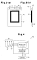
- Fig. 3(a) is a front view showing a mud guard to which a receiving antenna of the apparatus of Fig. 1 is attached;
- Fig. 3(b) is a side view showing the mud guard of Fig. 3(a);
- Fig. 4 is a block diagram showing a receiver installed in the apparatus of Fig. 1;
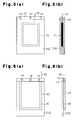
- Fig. 5(a) is a front view showing a modification of a mud guard with a built-in receiving antenna;
- Fig. 5(b) is a cross-sectional view showing the mud guard of Fig. 5(a);
- Fig. 6(a) is a front view showing a modification of a mud guard and a deflection stopper; and
- Fig. 6(b) is a side view showing the mud guard and the deflection stopper of Fig. 6(a).
-
- An embodiment of the present invention, or a wireless tire condition monitoring apparatus 1, will now be described with reference to Figs. 1 to 4.
- With reference to Fig. 1, the tire condition monitoring apparatus 1 includes four
transmitters 30 and asingle receiver 40. Each of thetransmitters 30 is associated with a different one of fourtires 20 of avehicle 10. Thereceiver 40 is installed in abody frame 11 of thevehicle 10. - Each
transmitter 30 is fixed to awheel 21 such that thetransmitter 30 is located in the associatedtire 20. Eachtransmitter 30 measures parameters indicating the condition of the associatedtire 20 or the air pressure of thetire 20. Thetransmitter 30 then wirelessly transmits data including air pressure data, which is obtained from the measurement, to thereceiver 40. - The
receiver 40 is installed at a predetermined location in thebody frame 11 and is powered by, for example, a battery (not shown) located in thevehicle 10. Thereceiver 40 includes fourreceiving antennas 41, each of which is associated with a different one of the fourtransmitters 30. Eachreceiving antenna 41 is connected to thereceiver 40 by acable 42. It is preferred that thecables 42 be coaxial cables, which are hardly affected by noise. Thereceiver 40 receives a signal from each of thetransmitters 30, mainly by the associated receivingantenna 41. - A
display 50 is located at a position visible from the driver of thevehicle 10. Thedisplay 50 is connected to thereceiver 40 by acable 43. - With reference to Fig. 2, each of the
transmitters 30 includes atransmission controller 31, which is formed by, for example, a microcomputer. Thetransmission controller 31 includes, for example, a central processing unit (CPU), a read only memory (ROM), and a random access memory (RAM). A specific identification (ID) code is pre-registered in an internal memory, for example, the ROM, of eachtransmitter 31. The identification codes identify the fourtransmitters 30. - In each
transmitter 30, apressure sensor 32 measures the air pressure of the associatedtire 20 and transmits air pressure data based on the measurement to thetransmission controller 31. Thetransmission controller 31 then supplies a transmittingcircuit 33 with data including a signal indicating the received air pressure data and the specific ID code registered in the internal memory of thetransmitter 30. Subsequently, the transmittingcircuit 33 encodes and modulates the data from thetransmission controller 31 before wirelessly transmitting the data by a transmittingantenna 34. Eachtransmitter 30 includes abattery 35, which powers thetransmitter 30. - With reference to Figs. 3(a) and 3(b), the
receiving antennas 41 are each attached to a mud guard of a different one of thetires 20. Themud guards 12 protect thebody frame 11 from mud or rain water splashed by the associatedtires 20. Themud guards 12 are each fixed to thebody frame 11 bymetal stays 13 andbolts 14. Themud guards 12 are formed of non-metallic insulating bodies, such as synthetic resin bodies. This prevents the radio waves transmitted by thetransmitters 30 from being interfered by metal bodies. The performance of thereceiver 40 is thus maintained. Each receivingantenna 41 is a so-called loop antenna, which is formed by winding an electric cable for a predetermined turns. More specifically, each receivingantenna 41 is attached to the side of themud guard 12 that faces the associatedtire 20. - With reference to Fig. 4, the
receiver 40 includes areception controller 44 and a receivingcircuit 45, which process received data. Thereception controller 44, which is formed by, for example, a microcomputer, includes a CPU, an ROM, and an RAM. When one of thetransmitters 30 transmits data to thereceiver 40, the receivingcircuit 45 receives the data from thetransmitter 30 mainly by the associated receivingantenna 41. The receivingcircuit 45 then demodulates and decodes the received data before transmitting the data to thereception controller 44. - Based on the received data, the
reception controller 44 recognizes the air pressure of thetire 20 associated with thetransmitter 30, which is the origin of the data. Thereception controller 44 then indicates the air pressure data on thedisplay 50. Particularly, if the air pressure of thetire 20 is abnormal, thereception controller 44 indicates so on thedisplay 50. - The illustrated embodiment has the following effects.
- (1) The mud guards 12, to which the receiving
antennas 41 are attached, are formed of non-metallic bodies and are spaced from any metallic bodies, including thebody frame 11. This prevents the performance of thereceiver 40 from being significantly hampered by any metallic body interfering with radio waves transmitted by thetransmitters 30. Thereceiver 40 thus stably receives and processes the data from thetransmitters 30. This enables thereceiver 40 to indicate a abnormal state of the air pressure of any of thetires 20 on thedisplay 50, if that is the case. - (2) Each of the receiving
antennas 41 is attached to the side of themud guard 12 that faces the associatedtire 20. The receivingantennas 41 are thus invisible from behind thevehicle 10. This maintains the appearance of thevehicle 10 regardless of the receivingantennas 41. Further, thereceiver 40 stably receives the data from thetransmitters 30. - (3) The receiving
antennas 41 are configured simply by attaching a looped electric wire to eachmud guard 12. That is, the receivingantennas 41 have a simple structure. Further, the manufacturing cost of the receivingantennas 41 is relatively low. -
- It should be apparent to those skilled in the art that the present invention may be embodied in many other specific forms without departing from the spirit or scope pf the invention. Particularly, it should be understood that the invention may be embodied in the following forms.
- With reference to Figs. 5(a) and 5(b), each of the receiving
antennas 41 may be built in amud guard 112. In this case, each of the mud guards 112 may be formed by a pair of resin sheets that clamp the receivingantenna 41. Alternatively, each receivingantenna 41 may be embedded integrally in the associatedmud guard 112 during molding of themud guard 112. In either case, the receivingantennas 41 are completely invisible from the exterior, thus maintaining the appearance of the mud guards 112. Further, thereceiver 40 stably receives data from thetransmitters 30. In addition, since the receivingantennas 41 are not exposed to the exterior, the receivingantennas 41 are reliably prevented from being damaged or deteriorated. - A
mud guard 212 illustrated in Figs. 6(a) and 6(b) is used for a large vehicle, such as a truck. Adeflection stopper 15, which prevents themud guard 212 from being deflected, is located at a position opposed to the mud guard 212 (at the side of themud guard 212 opposed to the side that faces the tire 20). Thedeflection stopper 15 is normally formed of conductive material, such as metal. Thedeflection stopper 15 is formed integrally with ametal stay 13 or is connected to thestay 13. In this manner, thestay 13 and thedeflection stopper 15 form a loop. Thus, thestay 13 and thedeflection stopper 15 may function together as each receivingantenna 41. More specifically, thestay 13 and thebolt 14, which are formed of metal, are electrically insulated from thebody frame 11 by a non-metallic body (an insulating body) 16, such as a resin spacer. This enables thedeflection stopper 15 to stop deflection of themud guard 212 and function also as the receivingantenna 41. It is thus unnecessary to install the receivingantennas 41 separately. This reduces the cost otherwise needed for the receivingantennas 41. - In the embodiments illustrated in Figs. 1 to 5(b), the receiving
antennas 41 may be formed by looped metal plates. - The receiving
antennas 41 may be each located at a portion of a side spoiler formed of insulating material including polypropylene (PP) or ABS resin, or a portion of a side spoiler that is located closest to the associatedtire 20. - The receiving
antennas 41 may be each located at a portion of a rear-under spoiler formed of insulating material including polypropylene (PP) or ABS resin, or a portion of a rear-under spoiler that is located closest to the associatedtire 20. - If the
vehicle 10 is provided with side steps, as in the case of a sport utility vehicle, the receivingantennas 41 may be installed in non-metallic bodies, such as resin moldings, of the side steps. - A warning beeper may be installed in the
vehicle 10 such that a beep indicates an abnormal state of the air pressure of any of thetires 20. Alternatively, a conventional speaker installed in thevehicle 10 may function as the warning beeper. - The air pressure data transmitted by each of the
transmitters 30 may specify the measurement of the air pressure of the associatedtire 20. Alternatively, the data may simply indicate whether or not the air pressure of thetire 20 is in an acceptable range. - A temperature sensor may be provided in each of the
transmitters 30. In this case, eachtransmitter 30 wirelessly transmits data regarding the temperature of the interior of the associatedtire 20, in addition to the air pressure data, as the condition of thetire 20. - The
vehicle 10 does not necessarily have to be a four-wheel vehicle. That is, the present invention may be applied to a two-wheel vehicle, such as a bicycle and a motorcycle, or a bus or a towed vehicle or an industrial vehicle (for example, a forklift). If the present invention is applied to the towed vehicle, thereceiver 40 and thedisplay 50 are installed in the towed vehicle. - The present examples and embodiments are to be considered as illustrative and not restrictive and the invention is not to be limited to the details given herein, but may be modified within the scope and equivalence of the appended claims.
Claims (7)
- An apparatus for monitoring the condition of a tire (20) of a vehicle, wherein the apparatus includes a transmitter (30) installed in the tire (20) for wirelessly transmitting data indicating the condition of the tire (20), a receiving antenna (41) that receives the data transmitted by the transmitter (30), and a receiver (40) installed in the vehicle for processing the data received by the receiving antenna (41), and the apparatus is characterized in that the receiving antenna (41) is attached to a non-metallic body of the vehicle that is located close to the tire (20).
- The apparatus according to claim 1, characterized in that the non-metallic body is a mud guard (12, 112, 212).
- The apparatus according to claim 2, characterized in that the receiving antenna (41) is built in the mud guard (112).
- The apparatus according to claim 2, characterized in that a deflection stopper (15) is attached to the mud guard (212) for stopping deflection of the mud guard (212), and that the deflection stopper (15) functions also as the receiving antenna (41).
- The apparatus according to claim 4, characterized in that the deflection stopper (15) is electrically insulated from a body frame of the vehicle by an insulating body (16).
- The apparatus according to any one of claims 1 to 5, characterized in that the receiving antenna (41) is installed in the non-metallic body such that the receiving antenna (41) is invisible from behind the vehicle.
- The apparatus according to claim 2, characterized in that the receiving antenna (41) is located at the side of the mud guard (12) that faces the tire (20) of the vehicle.
Applications Claiming Priority (2)
| Application Number | Priority Date | Filing Date | Title |
|---|---|---|---|
| JP2001362810A JP2003165313A (en) | 2001-11-28 | 2001-11-28 | Tire condition monitoring device |
| JP2001362810 | 2001-11-28 |
Publications (2)
| Publication Number | Publication Date |
|---|---|
| EP1316444A2 true EP1316444A2 (en) | 2003-06-04 |
| EP1316444A3 EP1316444A3 (en) | 2003-10-29 |
Family
ID=19173252
Family Applications (1)
| Application Number | Title | Priority Date | Filing Date |
|---|---|---|---|
| EP02009337A Withdrawn EP1316444A3 (en) | 2001-11-28 | 2002-05-02 | Tire condition monitoring apparatus |
Country Status (5)
| Country | Link |
|---|---|
| US (1) | US6774777B2 (en) |
| EP (1) | EP1316444A3 (en) |
| JP (1) | JP2003165313A (en) |
| KR (1) | KR100460693B1 (en) |
| TW (1) | TWI256923B (en) |
Cited By (4)
| Publication number | Priority date | Publication date | Assignee | Title |
|---|---|---|---|---|
| WO2004089658A1 (en) | 2003-04-02 | 2004-10-21 | The Yokohama Rubber Co., Ltd. | Communication system for tire |
| FR2872116A1 (en) * | 2004-06-29 | 2005-12-30 | Michelin Soc Tech | AUTOMOTIVE VEHICLE WHEEL PASSAGE COMPRISING AN ELECTRIC CIRCUIT AND ASSEMBLY OF A WHEEL PASSAGE AND FEED MEANS |
| EP1433626A3 (en) * | 2002-12-25 | 2006-01-25 | Pacific Industrial Co., Ltd. | Tire condition monitoring apparatus |
| CN101638039B (en) * | 2009-08-25 | 2012-05-23 | 深圳职业技术学院 | Vehicle-running wireless monitoring and recording device |
Families Citing this family (7)
| Publication number | Priority date | Publication date | Assignee | Title |
|---|---|---|---|---|
| JP2004149093A (en) * | 2002-11-01 | 2004-05-27 | Pacific Ind Co Ltd | Tire state monitor device |
| KR100571043B1 (en) * | 2003-10-29 | 2006-04-13 | 주식회사 현대오토넷 | Receiving Antenna of Tire Pressure Monitoring System Using Radial Leakage Coaxial Cable |
| JP4535742B2 (en) * | 2004-02-03 | 2010-09-01 | 株式会社シマノ | Fishing reel, fishing information display device and fishing information display system |
| JP4263213B2 (en) * | 2004-03-17 | 2009-05-13 | 横浜ゴム株式会社 | Antenna device |
| JP4599150B2 (en) * | 2004-12-14 | 2010-12-15 | 住友ゴム工業株式会社 | Pneumatic tire with electronic parts storage |
| EP1859968B1 (en) * | 2005-03-14 | 2011-12-21 | Bridgestone Corporation | Electronic device and tire |
| JP4797031B2 (en) | 2008-02-08 | 2011-10-19 | 日立オートモティブシステムズ株式会社 | Pressure measuring device and tire pressure monitoring system |
Family Cites Families (20)
| Publication number | Priority date | Publication date | Assignee | Title |
|---|---|---|---|---|
| US3873965A (en) * | 1974-04-18 | 1975-03-25 | George E Garcia | Tire pressure monitoring system |
| US4067235A (en) | 1974-11-27 | 1978-01-10 | Consolidated Freightways, Inc. | Method and apparatus for measuring air pressure in pneumatic tires |
| WO1986001465A1 (en) * | 1984-08-28 | 1986-03-13 | Noel Smith | Inflation pressure indicator for vehicle tyres |
| JPH05238427A (en) * | 1991-08-19 | 1993-09-17 | Bridgestone Corp | Splash preventing device for vehicle |
| KR970002202Y1 (en) * | 1993-10-14 | 1997-03-20 | 대우자동차 주식회사 | In-vehicle tire pressure tester |
| US5632551A (en) * | 1994-07-18 | 1997-05-27 | Grote Industries, Inc. | LED vehicle lamp assembly |
| DE19520674A1 (en) | 1995-06-07 | 1996-12-12 | Burkhard Weis | Continuous monitoring of vehicle tyre pressure during travel |
| JP3604509B2 (en) * | 1996-07-02 | 2004-12-22 | 横浜ゴム株式会社 | Vehicle tire pressure monitoring system |
| KR100286820B1 (en) * | 1996-09-03 | 2001-04-16 | 여두용 | Apparatus for measuring the pressure of an automobile tire |
| US6124787A (en) * | 1997-01-15 | 2000-09-26 | Algonquin Scientific, Llc | Tire pressure sensing system |
| JPH1199812A (en) * | 1997-09-30 | 1999-04-13 | Nissan Motor Co Ltd | Tire pressure drop detector |
| DE19748327A1 (en) * | 1997-10-31 | 1999-05-20 | Siemens Ag | Antenna device, in particular for an anti-theft system of a motor vehicle |
| US6304172B1 (en) * | 1998-11-27 | 2001-10-16 | Pacific Industrial Co., Ltd. | Receiver of tire inflation pressure monitor |
| US6591671B2 (en) | 1999-08-16 | 2003-07-15 | The Goodyear Tire & Rubber Company | Monitoring pneumatic tire conditions |
| JP2001108551A (en) * | 1999-10-13 | 2001-04-20 | Pacific Ind Co Ltd | Tire pneumatic pressure monitoring device and external communication device |
| US6517218B2 (en) * | 2000-03-31 | 2003-02-11 | Relume Corporation | LED integrated heat sink |
| DE10043757C1 (en) * | 2000-09-06 | 2001-11-15 | Bosch Gmbh Robert | Automobile antenna device has antenna structure on inside of wing protected from electrostatic discharge by conductive screening wall coupled to conductive chassis |
| KR20020096192A (en) * | 2001-06-18 | 2002-12-31 | 현대자동차주식회사 | ETACS to fulfill function of TPWS |
| US6932495B2 (en) * | 2001-10-01 | 2005-08-23 | Sloanled, Inc. | Channel letter lighting using light emitting diodes |
| GB0209190D0 (en) * | 2002-04-23 | 2002-06-05 | Lewis Keith | Lighting apparatus |
-
2001
- 2001-11-28 JP JP2001362810A patent/JP2003165313A/en active Pending
-
2002
- 2002-04-24 US US10/131,373 patent/US6774777B2/en not_active Expired - Fee Related
- 2002-05-02 EP EP02009337A patent/EP1316444A3/en not_active Withdrawn
- 2002-05-03 KR KR10-2002-0024441A patent/KR100460693B1/en not_active Expired - Fee Related
- 2002-05-16 TW TW091110327A patent/TWI256923B/en not_active IP Right Cessation
Non-Patent Citations (1)
| Title |
|---|
| None * |
Cited By (7)
| Publication number | Priority date | Publication date | Assignee | Title |
|---|---|---|---|---|
| EP1433626A3 (en) * | 2002-12-25 | 2006-01-25 | Pacific Industrial Co., Ltd. | Tire condition monitoring apparatus |
| WO2004089658A1 (en) | 2003-04-02 | 2004-10-21 | The Yokohama Rubber Co., Ltd. | Communication system for tire |
| EP1609627A4 (en) * | 2003-04-02 | 2011-12-28 | Yokohama Rubber Co Ltd | Communication system for tire |
| FR2872116A1 (en) * | 2004-06-29 | 2005-12-30 | Michelin Soc Tech | AUTOMOTIVE VEHICLE WHEEL PASSAGE COMPRISING AN ELECTRIC CIRCUIT AND ASSEMBLY OF A WHEEL PASSAGE AND FEED MEANS |
| WO2006000572A1 (en) * | 2004-06-29 | 2006-01-05 | Societe De Technologie Michelin | Motor vehicle wheel housing comprising an electric circuit, and assembly comprising a wheel housing and power means |
| CN100484783C (en) * | 2004-06-29 | 2009-05-06 | 米其林技术公司 | Motor vehicle wheel housing comprising an electric circuit, and assembly comprising a wheel housing and power means |
| CN101638039B (en) * | 2009-08-25 | 2012-05-23 | 深圳职业技术学院 | Vehicle-running wireless monitoring and recording device |
Also Published As
| Publication number | Publication date |
|---|---|
| KR100460693B1 (en) | 2004-12-08 |
| JP2003165313A (en) | 2003-06-10 |
| KR20030043580A (en) | 2003-06-02 |
| EP1316444A3 (en) | 2003-10-29 |
| US6774777B2 (en) | 2004-08-10 |
| TWI256923B (en) | 2006-06-21 |
| US20030098788A1 (en) | 2003-05-29 |
Similar Documents
| Publication | Publication Date | Title |
|---|---|---|
| EP1004461B1 (en) | Receiver of tire inflation pressure monitor | |
| US9738122B2 (en) | Tire provided with information acquisition device | |
| US6963274B2 (en) | Transmitter of tire condition monitoring apparatus and tire condition monitoring apparatus | |
| US7212105B2 (en) | Transmitter for tire condition monitoring apparatus | |
| US7034672B2 (en) | Tire sensor | |
| US6774777B2 (en) | Tire condition monitoring apparatus | |
| JP2003175711A (en) | Tire state monitoring device | |
| US20040257213A1 (en) | Transmitter of tire condition monitoring apparatus and tire condition monitoring apparatus | |
| JP2004262324A (en) | Transmitter of tire state monitoring device and tire state monitoring device | |
| JP3949568B2 (en) | Transponder for tire condition monitoring device | |
| US6885292B2 (en) | Tire condition monitoring apparatus | |
| EP1468847B1 (en) | Tire condition monitoring apparatus | |
| US6922141B2 (en) | Mounting structure of transmitter for tire condition monitoring apparatus | |
| US20040135681A1 (en) | Tire condition monitoring apparatus | |
| CA2840466A1 (en) | Diversity antenna | |
| EP1500528A1 (en) | Transmitter and receiver for tire condition monitoring apparatus | |
| EP1757465B1 (en) | Tire condition detecting device | |
| US7187272B2 (en) | Casing structure of transmitter of tire condition monitoring apparatus | |
| KR200450432Y1 (en) | Pressure sensor for tire pressure measurement and tire air pressure monitoring system | |
| US6670886B1 (en) | Tire pressure monitoring device and antenna therefor | |
| JP2006327460A (en) | Tire air pressure warning system | |
| JP2006306184A (en) | Wheel side antenna device and tire state detecting device having the same |
Legal Events
| Date | Code | Title | Description |
|---|---|---|---|
| PUAI | Public reference made under article 153(3) epc to a published international application that has entered the european phase |
Free format text: ORIGINAL CODE: 0009012 |
|
| AK | Designated contracting states |
Designated state(s): AT BE CH CY DE DK ES FI FR GB GR IE IT LI LU MC NL PT SE TR |
|
| AX | Request for extension of the european patent |
Extension state: AL LT LV MK RO SI |
|
| PUAL | Search report despatched |
Free format text: ORIGINAL CODE: 0009013 |
|
| AK | Designated contracting states |
Kind code of ref document: A3 Designated state(s): AT BE CH CY DE DK ES FI FR GB GR IE IT LI LU MC NL PT SE TR |
|
| AX | Request for extension of the european patent |
Extension state: AL LT LV MK RO SI |
|
| 17P | Request for examination filed |
Effective date: 20040304 |
|
| AKX | Designation fees paid |
Designated state(s): DE FR GB |
|
| 17Q | First examination report despatched |
Effective date: 20061205 |
|
| STAA | Information on the status of an ep patent application or granted ep patent |
Free format text: STATUS: THE APPLICATION IS DEEMED TO BE WITHDRAWN |
|
| 18D | Application deemed to be withdrawn |
Effective date: 20070417 |