EP1316103B1 - Large surface area x-ray tube shield structure - Google Patents
Large surface area x-ray tube shield structure Download PDFInfo
- Publication number
- EP1316103B1 EP1316103B1 EP01963934A EP01963934A EP1316103B1 EP 1316103 B1 EP1316103 B1 EP 1316103B1 EP 01963934 A EP01963934 A EP 01963934A EP 01963934 A EP01963934 A EP 01963934A EP 1316103 B1 EP1316103 B1 EP 1316103B1
- Authority
- EP
- European Patent Office
- Prior art keywords
- coolant
- ray tube
- shield structure
- fluid
- fluid passageway
- Prior art date
- Legal status (The legal status is an assumption and is not a legal conclusion. Google has not performed a legal analysis and makes no representation as to the accuracy of the status listed.)
- Expired - Lifetime
Links
- 239000012530 fluid Substances 0.000 claims abstract description 156
- 239000002826 coolant Substances 0.000 claims abstract description 149
- 238000001816 cooling Methods 0.000 claims abstract description 71
- 238000009835 boiling Methods 0.000 claims abstract description 17
- 239000007788 liquid Substances 0.000 claims description 44
- 238000004891 communication Methods 0.000 claims description 18
- 239000000463 material Substances 0.000 claims description 9
- 238000000034 method Methods 0.000 claims description 6
- 229910000881 Cu alloy Inorganic materials 0.000 claims description 3
- 229910001175 oxide dispersion-strengthened alloy Inorganic materials 0.000 claims description 3
- TWNQGVIAIRXVLR-UHFFFAOYSA-N oxo(oxoalumanyloxy)alumane Chemical compound O=[Al]O[Al]=O TWNQGVIAIRXVLR-UHFFFAOYSA-N 0.000 claims description 3
- 238000007599 discharging Methods 0.000 claims description 2
- 230000037361 pathway Effects 0.000 claims 2
- 230000017525 heat dissipation Effects 0.000 claims 1
- 238000012546 transfer Methods 0.000 abstract description 45
- 230000000694 effects Effects 0.000 abstract description 13
- 230000003190 augmentative effect Effects 0.000 abstract description 5
- 230000004907 flux Effects 0.000 abstract description 3
- 230000035882 stress Effects 0.000 description 16
- 230000001965 increasing effect Effects 0.000 description 11
- 230000006872 improvement Effects 0.000 description 5
- 230000001066 destructive effect Effects 0.000 description 4
- 230000008646 thermal stress Effects 0.000 description 4
- 238000013459 approach Methods 0.000 description 3
- 230000015572 biosynthetic process Effects 0.000 description 3
- 230000015556 catabolic process Effects 0.000 description 3
- 230000003247 decreasing effect Effects 0.000 description 3
- 230000009977 dual effect Effects 0.000 description 3
- 238000004519 manufacturing process Methods 0.000 description 3
- RYGMFSIKBFXOCR-UHFFFAOYSA-N Copper Chemical compound [Cu] RYGMFSIKBFXOCR-UHFFFAOYSA-N 0.000 description 2
- 238000004458 analytical method Methods 0.000 description 2
- 230000008901 benefit Effects 0.000 description 2
- 238000005219 brazing Methods 0.000 description 2
- 230000000295 complement effect Effects 0.000 description 2
- 238000005520 cutting process Methods 0.000 description 2
- 230000007423 decrease Effects 0.000 description 2
- 230000013011 mating Effects 0.000 description 2
- 230000006911 nucleation Effects 0.000 description 2
- 238000010899 nucleation Methods 0.000 description 2
- 230000008569 process Effects 0.000 description 2
- 230000003746 surface roughness Effects 0.000 description 2
- 230000003416 augmentation Effects 0.000 description 1
- 230000002301 combined effect Effects 0.000 description 1
- 239000004020 conductor Substances 0.000 description 1
- 239000012809 cooling fluid Substances 0.000 description 1
- 229910052802 copper Inorganic materials 0.000 description 1
- 239000010949 copper Substances 0.000 description 1
- 239000011889 copper foil Substances 0.000 description 1
- 230000001419 dependent effect Effects 0.000 description 1
- 238000009826 distribution Methods 0.000 description 1
- 238000005516 engineering process Methods 0.000 description 1
- 230000002708 enhancing effect Effects 0.000 description 1
- 230000002045 lasting effect Effects 0.000 description 1
- 238000012423 maintenance Methods 0.000 description 1
- 230000007246 mechanism Effects 0.000 description 1
- 230000035515 penetration Effects 0.000 description 1
- 230000005855 radiation Effects 0.000 description 1
- 230000009467 reduction Effects 0.000 description 1
- 239000004065 semiconductor Substances 0.000 description 1
- 230000000638 stimulation Effects 0.000 description 1
- 238000012360 testing method Methods 0.000 description 1
- 230000001225 therapeutic effect Effects 0.000 description 1
Images







Classifications
-
- H—ELECTRICITY
- H05—ELECTRIC TECHNIQUES NOT OTHERWISE PROVIDED FOR
- H05G—X-RAY TECHNIQUE
- H05G1/00—X-ray apparatus involving X-ray tubes; Circuits therefor
- H05G1/02—Constructional details
- H05G1/04—Mounting the X-ray tube within a closed housing
-
- H—ELECTRICITY
- H01—ELECTRIC ELEMENTS
- H01J—ELECTRIC DISCHARGE TUBES OR DISCHARGE LAMPS
- H01J35/00—X-ray tubes
- H01J35/02—Details
- H01J35/16—Vessels; Containers; Shields associated therewith
-
- H—ELECTRICITY
- H05—ELECTRIC TECHNIQUES NOT OTHERWISE PROVIDED FOR
- H05G—X-RAY TECHNIQUE
- H05G1/00—X-ray apparatus involving X-ray tubes; Circuits therefor
- H05G1/02—Constructional details
- H05G1/025—Means for cooling the X-ray tube or the generator
-
- H—ELECTRICITY
- H05—ELECTRIC TECHNIQUES NOT OTHERWISE PROVIDED FOR
- H05G—X-RAY TECHNIQUE
- H05G1/00—X-ray apparatus involving X-ray tubes; Circuits therefor
- H05G1/02—Constructional details
- H05G1/04—Mounting the X-ray tube within a closed housing
- H05G1/06—X-ray tube and at least part of the power supply apparatus being mounted within the same housing
-
- H—ELECTRICITY
- H01—ELECTRIC ELEMENTS
- H01J—ELECTRIC DISCHARGE TUBES OR DISCHARGE LAMPS
- H01J2235/00—X-ray tubes
- H01J2235/12—Cooling
-
- H—ELECTRICITY
- H01—ELECTRIC ELEMENTS
- H01J—ELECTRIC DISCHARGE TUBES OR DISCHARGE LAMPS
- H01J2235/00—X-ray tubes
- H01J2235/12—Cooling
- H01J2235/1216—Cooling of the vessel
-
- H—ELECTRICITY
- H01—ELECTRIC ELEMENTS
- H01J—ELECTRIC DISCHARGE TUBES OR DISCHARGE LAMPS
- H01J2235/00—X-ray tubes
- H01J2235/12—Cooling
- H01J2235/1225—Cooling characterised by method
- H01J2235/1245—Increasing emissive surface area
- H01J2235/125—Increasing emissive surface area with interdigitated fins or slots
-
- H—ELECTRICITY
- H01—ELECTRIC ELEMENTS
- H01J—ELECTRIC DISCHARGE TUBES OR DISCHARGE LAMPS
- H01J2235/00—X-ray tubes
- H01J2235/12—Cooling
- H01J2235/1225—Cooling characterised by method
- H01J2235/1262—Circulating fluids
-
- H—ELECTRICITY
- H01—ELECTRIC ELEMENTS
- H01J—ELECTRIC DISCHARGE TUBES OR DISCHARGE LAMPS
- H01J2235/00—X-ray tubes
- H01J2235/12—Cooling
- H01J2235/1225—Cooling characterised by method
- H01J2235/1262—Circulating fluids
- H01J2235/1283—Circulating fluids in conjunction with extended surfaces (e.g. fins or ridges)
-
- H—ELECTRICITY
- H01—ELECTRIC ELEMENTS
- H01J—ELECTRIC DISCHARGE TUBES OR DISCHARGE LAMPS
- H01J2235/00—X-ray tubes
- H01J2235/16—Vessels
- H01J2235/165—Shielding arrangements
- H01J2235/168—Shielding arrangements against charged particles
Definitions
- the coding system further includes means for facilitating nucleate boiling of the cooling fluid flowing through the fluid passageway.
- extended surfaces may be employed in conjunction with one or more of surfaces 111, 113, and 115.
- the extended surfaces may be formed separately and subsequently attached to one or more of surfaces 111, 113, or 115.
- the formation of the microgrooves and microridges on at least some portions of the wetted perimeter of fluid passageway 131 may be such that they are arranged substantially parallel to each other and to the flow of liquid coolant 114 through shield structure 108 and aperture disk 137.
- Exemplary arrangements include, but are not limited to, those wherein the microgrooves and microridges are disposed in a concentric or phonographic arrangement. It will be appreciated that such arrangements serve to facilitate a relative increase in heat transfer from shield structure 108 to liquid coolant 114, without materially impairing the pressure or flow rate of liquid coolant 114 passing through shield structure 108 and aperture disk 137.
- microgrooves 111 A, 113A, and 115A, and microridges 111 B, 113B, and 115B serve to, among other things, provide a relative increase in the overall surface area of shield structure 108 that is in contact with the liquid coolant 114 flowing through fluid passageway 131, the overall rate of heat transfer from shield structure 108 to liquid coolant 114 is correspondingly increased. This effect is explained at least in part by the well-known relationship, discussed elsewhere herein, between the size of a particular surface area and the rate of heat transfer across that particular surface.
- the two flows of coolant traverse the upper half of shield structure 108', converge, and then exit at an outlet port hole (not shown) formed in manifold inlet/outlet connection 118 and in fluid communication with fluid passageway 132.
- Outlet fluid conduit 120 is in fluid communication with the reservoir, as is indicated by the fluid flow line.
- the embodiment of the cooling system illustrated in Figure 14 enhances cooling of the x-ray tube by: i) providing cooling fins 110 to increase the surface area of the x-ray tube, and in particular the shield structure 108, thereby increasing the rate of convective heat transfer from the x-ray tube structures to the reservoir coolant; ii) directing a portion of the manifold coolant discharge across the fins to increase convective heat transfer from the fins, thus augmenting the convective cooling effect of the fins; and iii) convectively cooling the interior of the shield structure.
- the combined effect of the fluid passageways, external fins, and dual discharge manifold is to significantly increase the rate at which heat is removed from the x-ray tube.
- the enhanced heat transfer rate serves to reduce x-ray tube operating temperatures and thus the resultant thermal mechanical stresses, and substantially prevents thermal breakdown of the coolant, thereby extending the life of the coolant and, accordingly, the x-ray tube.
Landscapes
- X-Ray Techniques (AREA)
- Analysing Materials By The Use Of Radiation (AREA)
- Laminated Bodies (AREA)
Abstract
Description
- The present invention relates generally to x-ray tubes. More particularly, embodiments of the present invention relate to an x-ray tube cooling system that increases the rate of heat transfer from the x-ray tube to a cooling system medium, thereby significantly reducing heat-induced stress and strain in x-ray tube structures and extending the operating life of the device.
- X-ray producing devices are extremely valuable tools that are used in a wide variety of applications, both industrial and medical. For example, such equipment is commonly used in areas such as diagnostic and therapeutic radiology; semiconductor manufacture and fabrication; and materials analysis and testing.
- While used in a number of different applications, the basic operation of x-ray devices is similar. In general, x-rays, or x-ray radiation, are produced when electrons are produced and released, accelerated, and then stopped abruptly. The typical basic x-ray tube has a cathode cylinder with an electron generator, or cathode, at one end. Electrical power applied to a filament portion of the cathode generates electrons by thermionic emission. A target anode is axially spaced apart from the cathode, and is oriented so as to receive electrons emitted by the cathode. Also present is a voltage source that is used to apply a high voltage potential between the cathode and the anode.
- In operation, the high voltage potential is applied between the cathode and the anode, which causes the thermionically emitted electrons to accelerate away from the cathode and towards the anode in an electron stream. The accelerating electrons then strike the target anode surface (or focal track) at a high velocity. The target surface on the anode is composed of a material having a high atomic number, and a portion of the kinetic energy of the striking electron stream is thereby converted to electromagnetic waves of very high frequency, i.e., x-rays. The resulting x-rays emanate from the target surface, and are then collimated through a window formed in the x-ray device for penetration into an object, such as a patient's body. As is well known, the x-rays that pass through the object can be detected and analyzed so as to be used in any one of a number of applications, such as x-ray medical diagnostic examination or material analysis procedures.
- A percentage of the electrons that strike the anode target surface do not generate x-rays, and instead simply rebound from the surface. These are often referred to as "back-scatter" electrons. In some x-ray tubes, some of these rebounding electrons -- still traveling at relatively high velocities -- are blocked and collected by a shield structure that is positioned between the cathode and the anode so the rebounding electrons do not re-strike the target surface of the anode. In this way, the rebounding electrons are prevented from re-impacting the target anode and producing "off-focus" x-rays, which can negatively affect the quality of the x-ray image. Some of the rebounding electrons may also impact the interior of the cathode cylinder.
- While such a shield structure may prevent rebounding electrons from re-striking the anode target, its use can result in additional problems that can ultimately damage the x-ray tube device, and shorten its operational life. In particular, the high kinetic energy of the rebounding electrons is converted to thermal energy by the impact of those electrons on the shield structure or on the interior of the cathode cylinder. Due to the high level of kinetic energy of the electrons, the thermal energy produced by these impacts is significant and typically results in very high temperatures in the x-ray tube structures. These high temperatures, in combination with the high temperatures also being generated at the target anode, cause thermal stresses in the structures (including the cathode cylinder and the shield) and structure joints that can, especially over time, lead to various structural failures in the x-ray tube assembly. Moreover, because the rebounding electrons impact some portions of the cathode cylinder and shield structure with relatively greater frequency than other portions, the heat produced by the rebounding electrons is not evenly distributed. Accordingly, the different heat regions are collectively characterized by varying rates of thermal expansion, resulting in mechanical stresses that can also damage the x-ray tube device, especially over numerous operating cycles.
- For instance, mechanical stress and strain is induced when the cooler part of the structure resists the expansion of the hotter portion of the structure. The level of stress and strain is relatively insignificant at low temperature differentials. However, non-uniform expansion produced by high temperature differentials induces destructive mechanical stresses and strains that can ultimately cause a mechanical failure in the part. Moreover, these stresses are especially damaging to joints between attached components.
- Because such high temperatures can cause destructive thermal stresses and strains in the shield structure, the cathode cylinder, and in other parts of the x-ray device, attempts have been made to minimize thermal stress and strain through the use of various types of cooling systems. However, previously available x-ray tube cooling systems have not been entirely satisfactory in providing effective and efficient cooling - especially in the regions of the shield structure and cathode cylinder.
- In order to dissipate the high heat present, x-ray tubes have typically utilized some type of liquid cooling arrangement. In such systems, at least some ofthe external surfaces of the cathode cylinder are placed in direct contact with a circulating coolant, which facilitates a convective cooling process. Often however, this approach is not satisfactory for cooling an adjacent shield structure, which has a limited external surface area, and, because it is exposed to extremely high temperatures from rebounding electrons, is unable to efficiently transfer significant amounts of heat by convection to the coolant.
- To address this problem, shield structures have been fashioned with internal cooling passages through which a coolant stream is circulated.
US-A-6 115 454 discloses such a shield stucture. Thus, the shield structure gives up heat primarily by convection to the coolant which flows through its interior. This approach has not been entirely satisfactory either. Due to the limited size of such cooling passages, only a limited amount of heat can be absorbed by the coolant, and consequently the shield structure may not be adequately cooled. Thus, x-ray devices of this sort may experience greater failure rates and shorter operating lives due to repeated exposure to higher temperatures and resultant stresses. - Also, in systems of this sort, the coolant must be capable of absorbing significant amounts of heat in order to preclude harmful thermal stresses and strain in the shield structure and cathode cylinder. However, with current designs, the circulated coolant eventually, and often prematurely, experiences thermal breakdown and is no longer able to effectively remove heat from the x-ray tube. Again, this translates into an x-ray device that is more subject to failure and that typically has an overall shorter operating life.
- Currently available cooling system designs are lacking in another respect as well. As noted, heat produced within the x-ray tube is not evenly distributed. However, currently available cooling systems are not capable of removing heat from certain higher-temperature areas of the x-ray tube faster than cooler areas. Instead, the rate of heat transfer is fairly constant throughout the x-ray tube in existing systems. As such, those regions that are exposed to higher temperatures are not adequately cooled, and experience a greater failure rate.
- There are additional problems in existing x-ray tube designs caused by excessive operating temperatures. In particular, the high operating temperatures are especially destructive to the connection points between the various component parts of the x-ray tube device. For instance, the cathode cylinder is fashioned as a single integral part that must be attached to the shield structure. The shield structure is then affixed to the housing, or "can," that encloses the x-ray tube assembly. Typically, these attachments are accomplished by way of a weld or braze joint. However, in prior art systems, these joints have been implemented in a manner that is especially vulnerable to the thermal and mechanical stresses present, and often fail prematurely. Thus, efficient removal of heat, as well as robust joint attachments between component parts is critical to maintaining structural integrity and increased operating life of the x-ray device.
- Thus, there is a need in the art for a cooling system that can be used to efficiently and effectively remove heat from the x-ray tube, and especially in the areas of the cathode cylinder and the adjacent shield structure. Moreover, it would be desirable to have a system that provides sufficient heat removal to reduce the level of thermal and mechanical stresses otherwise present within the cathode cylinder and shield, and that would thereby increase the overall operating life of the x-ray tube and x-ray device. Likewise, the system should prevent heat-related damage from occurring in the materials used to fabricate the cathode cylinder and shield assembly, and should reduce structural damage from occurring between joints and/or attachment points between the various structural components. Joints between components should be more robust, and able to withstand high temperatures. Also, it would be desirable if the system could effectively remove heat at a higher rate from those areas of the system that experience higher temperatures than other portions, and thereby reduce the occurrence of varying thermal regions.
- The present invention is defined in the independent claims, with optional features being defined in the dependent claims.
- Briefly summarized, embodiments of the present invention are directed to an x-ray tube having improved cooling characteristics. In one preferred embodiment, an x-ray tube system includes a reservoir containing a liquid coolant that is continuously circulated by way of a heat exchanger device. Disposed within the coolant reservoir is an x-ray tube having an outer evacuated housing. The evacuated housing encloses an electron source, such as a cathode head assembly, and an anode having a target surface capable of receiving electrons emitted by the electron source. Disposed between the cathode head assembly and the anode is a shield structure. The shield structure defines an aperture through which electrons are passed from the electron source to the target surface to generate x-rays. Moreover, the shield structure provides an electron collection surface, that prevents electrons that rebound from the target surface from re-striking the target.
- In embodiments of the invention at least one fluid passageway is formed within the shield structure. The fluid passageway receives coolant from the reservoir from an inlet port, which then passes through the passageway so as to absorb heat generated in the shield structure, including heat generated as a result of rebounding electrons striking inner surfaces of the shield.
- In all embodiments, the cooling system also includes a plurality of extended surfaces, or cooling fins, that are affixed to the outer surface of the shield structure. Coolant exiting the fluid passageway is allowed to flow across the extended surfaces, which are oriented in a manner so as to conduct heat from the shield to the coolant.
- The coding system further includes means for facilitating nucleate boiling of the cooling fluid flowing through the fluid passageway.
- In one preferred embodiment, the cooling system also includes means for augmenting the heat transfer capability of the fluid passageway. In an illustrated embodiment, this means is comprised of a plurality of microgrooves formed inside the fluid passageway cooperatively defined by the shield structure and the aperture disk. The microgrooves serve to increase the surface area of the fluid passageway through which the coolant flows and thereby effect a relative increase in the rate of heat transfer from the shield structure to the coolant. Additionally, the microgrooves also improve the efficiency of multi-phase heat transfer, beyond the improvement attributable simply to the increase in surface area, by enhancing the mechanism by which ebullition heat transfer, i.e., nucleate boiling occurs.
- In an alternative embodiment, the aforementioned means for augmenting the heat transfer capability of the fluid passageway comprises a coiled spring that is disposed within the fluid passageway. The spring provides an extended surface that increases the efficiency and rate at which heat is removed from the shield structure by the coolant.
- In yet another preferred embodiment, the fluid passageways that are formed within the shield structure are oriented in a manner that permits coolant to flow through a first and a second section of the shield structure. Moreover, the passageways are further oriented such that the heat is transferred away from the first section at a greater rate than in the second section. In this way, those sections (i.e., the first section) having a higher thermal content are cooled at a faster rate than those sections (i.e., the second section) having a lower thermal content. This ensures a more efficient and evenly distributed dissipation of heat, and also helps ensure that the coolant is not overly thermally stressed.
- Embodiments of the invention also are disclosed that provide a more structurally sound x-ray tube assembly, and one that is thus better able to withstand the thermal and mechanical stresses present in an operating tube. For instance, an improved braze joint is provided between the shield structure and the x-ray tube housing. In particular, a braze material is placed along a joint formed along both a horizontal and a vertical surface of the shield structure and the x-ray tube housing. This ensures a connection joint that is more structurally sound, and that is able to survive the varying temperatures, and resultant stresses imposed during operation of the x-ray tube.
- In order to more fully understand the manner in which the above-recited and other advantages and objects of the invention are obtained, a more particular description of the invention will be rendered by reference to specific embodiments thereof which are illustrated in the appended drawings. Understanding that these drawings depict only typical embodiments of the invention and are not therefore to be considered to be limiting of its scope, the invention in its presently understood best mode for making and using the same will be described and explained with additional specificity and detail through the use of the accompanying drawings in which:
-
Figure 1 is a plan view of one preferred embodiment of the cooling system; -
Figure 2 is an isometric cross-section view of an embodiment of the cathode cylinder and shield structure depicted inFigure 1 ; -
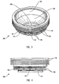
Figure 3 is a perspective view of an embodiment of the shield structure; -
Figure 4 is a side view of the embodiment of the shield structure ofFigure 3 ; -
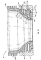
Figure 5A is a cross-section view of an embodiment of the shield assembly; -
Figure 5B is a plan view of an embodiment of an aperture disk; -
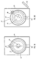
Figure 6A is a plan view of an embodiment of an aperture disk, indicating the flow path of coolant through the lower fluid passageway of the shield assembly; -
Figure 6B is a plan view of an alternative embodiment of the aperture disk indicated inFigure 6A ; -
Figure 7 is a perspective view of another embodiment of the shield assembly; -
Figure 8 is a side view of the embodiment of the shield structure ofFigure 7 ; -
Figure 9 is a plan view ofthe embodiment ofthe shield structure ofFigure 7 ; -
Figure 10 is a cross-section of the embodiment of the shield structure ofFigure 7 ; -
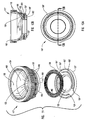
Figure 11 is an exploded perspective view of another embodiment of the shield structure; -
Figure 12A is a plan view of the embodiment of the shield structure depicted inFigure 11 ; -
Figure 12B is a cross-section view, taken along line 12B-12B inFigure 12A , of the embodiment of the shield structure depicted inFigure 11 ; -
Figure 13A is a plan view of another embodiment of the aperture disk, indicating the flow path of coolant through the lower fluid passageway of the shield assembly; -
Figure 13B is a plan view of an alternative embodiment of the aperture disk indicated inFigure 13A ; -
Figure 14 is a plan view of an alternative embodiment of the cooling system; -
Figure 15 is a cross-section view of a cathode cylinder, shield assembly, and can; and -
Figure 16 is a detail view taken along line 16-16 inFigure 15 , showing an embodiment of a braze joint configuration between the aperture disk and the can. - Reference will now be made to the figures, wherein like structures will be provided with like reference designations. It is to be understood that the drawings are diagrammatic and schematic representations of presently preferred embodiments of the present invention and are not limiting of the present invention, nor are they necessarily drawn to scale.
- Referring first to
Figures 1 and2 together, the relevant portions of an x-ray tube device are depicted generally at 100. An x-ray tube, designated generally at 101, is formed generally with an evacuated envelope housing that is typically referred to as a "can" 107. The evacuated envelope, or can, 107 is disposed within ahousing 112. Disposed withincan 107 is an electron source in the form ofacathode head 106, filament (not shown) and associated electronics (not shown), that is disposed within acathode cylinder 102 portion of the evacuatedenvelope 107. Adjacent to thecathode 106, and attached to the end ofcathode cylinder 102, is a electron collection device, sometimes referred to as an "aperture," and referred to herein as ashield assembly 117 which comprises ashield structure 108, and aperture disk 137 (discussed in further detail below). Also disposed within thex-ray tube 101 is arotating target anode 104, which is axially disposed opposite to thecathode head 106. A voltage source is connected torotating target anode 104 andcathode head 106, and electrons emitted by thecathode 106 are accelerated when a voltage difference is applied between the cathode and anode. As the high velocity electrons stream towards the anode, they pass through anaperture 122 formed within theshield structure 108. When the electrons impact the surface of thetarget anode 104, a portion of their kinetic energy stimulates emission of x-rays. These x-rays are then partially collimated and emitted through a window 103 (Figure 1 ) formed in the side of thex-ray tube 101, and a corresponding window in the housing 112 (not shown). - As previously noted and as will be discussed in further detail below, some of the electrons that strike the surface of
rotating target anode 104 do not stimulate emission of x-rays. Instead, they may rebound fromrotating target anode 104. As will be discussed further below, theshield structure 108 performs a number of valuable functions, including preventing the rebounding electrons from descending and re-strikingrotating target anode 104 -- and thereby generating off-focus x-rays. In addition, some of the rebounding electrons will strike the inner surface of thecathode cylinder 102. While these rebounding electrons are thus prevented from re-strikingrotating target anode 104, they are still traveling at relatively high velocities and thus still generate large amounts of heat within theshield structure 108 and thecathode cylinder 102 when they strike those structures. Consequently, this heat, in addition to the heat generated atrotating target anode 104, must be continuously removed away from thex-ray tube 101, or damage to the device may occur. As noted, excessive heat in the shield structure and the cathode housing can be problematic, particularly if shield structure and/or cathode housing are exposed to excessive heat over a relatively long period of time. -
Figure 1 illustrates how in one presently preferred embodiment, thex-ray tube 101 is completely immersed within aliquid coolant 114 that is disposed within the reservoir formed by thehousing 112. As contemplated herein, "liquid coolant" includes, but is not limited to, coolants substantially comprising a liquid, as well as coolants comprising both vapor and liquid components. - During operation of the x-ray device, the coolant is re-circulated through the
housing 112 via a heat exchanger/cooling unit 134. As the coolant is circulated through thehousing 112, heat is dissipated from the x-ray tube components and absorbed by the coolant. Heated coolant is then circulated to the heat exchanger/cooling unit 134, where heat is removed by any appropriate means, such as a radiative surface or the like. The cooled liquid is then re-circulated back to the housing reservoir. - Generally, the rate of heat transfer is in part a function of the size of the surface area across which the heat is transferred. Thus, as noted above, the efficiency at which heat is conducted from the x-ray tube to the coolant is based partly upon the surface area of the component being cooled, which in the past has been limited -- especially in the problematic areas of the shield structure and the
cathode cylinder 102. Embodiments of the present invention address this problem by way of theshield structure 108, a preferred embodiment ofwhich is shown generally inFigure 1 , and in further detail inFigures 2 ,3 ,4 and5A . As is shown best inFigures 1 ,2 and15 , theshield structure 108 interconnects the main body portion ofcan 107 of thex-ray tube 101 with thecathode cylinder 102. In the illustrated embodiment, theshield structure 108 includes a separate bottom cover, referred to as the aperture disk 137 (seeFigures 2 ,5A and15 ), that is affixed to the bottom of theshield structure 108. Theaperture disk 137 is in turn affixed to acorresponding recess 155 formed within thecan 107. Preferably, the attachment is accomplished with a braze joint, which is described in further detail below. In a presently preferred embodiment, theshield structure 108 and theaperture disk 137 are each constructed of a aluminum oxide dispersion strengthened copper alloy, such as the material known by the tradename Glidcop AL-15 UNS C-15715 and sold by OMG Americas Inc. Other materials could also be used, including but not limited to Glidcop AL-25, and Glidcop AL-60 UNS C-15725 and UNS C-15760 respectively. - As is best seen in
Figures 2 and3 ,aperture 122 ofshield structure 108 andaperture disk 137 allows the electron stream to pass from thecathode head 106 to rotating target anode 104 (Figure 2 ). Also, disposed about theaperture 122 is anelectron collection surface 124, which provides the function of preventing rebounding electrons from descending and re-strikingrotating target anode 104. Theelectron collection surface 124 is shaped and oriented in a manner such that the trajectory of rebounding electrons will cause them to strike theelectron collection surface 124 instead of returning to the surface ofrotating target anode 104. In the illustrated embodiment, theelectron collection surface 124 is sloped towards theaperture 122 with a concave shape. It will be appreciated that other shapes and contours could be used. - In a presently preferred embodiment, the shield structure includes a means for transferring heat away from the shield structure. By way of example and not limitation, in one preferred embodiment the heat transfer means is comprised of a plurality of cooling members or "fins," which are designated at 110 in
Figure 1 and are shown in further detail inFigures 2 ,3 ,4 and5A . These coolingfins 110 are comprised of adjacent annular extended surfaces formed about the periphery of the outer surface of theshield structure 108, and are at least partially exposed to theliquid coolant 114 disposed in the reservoir ofhousing 112, as is indicated inFigure 1 . - In general, the cooling
fins 110 effectively increase the amount ofsurface area of theshield structure 108 that is in contact with the reservoir coolant, and they thereby function to increase the efficiency and rate at which heat is conducted and transferred from the shield to the coolant. This can best be seen in the views of an embodiment ofshield structure 108 indicated inFigures 3 and 4 . As is illustrated, the plurality of coolingfins 110 are formed about the entire outer surface oftheshield structure 108, and are spaced apart so as to permit coolant to flow between the fins, and to maximize that portion of the surface area ofshield assembly 117 that is exposed to the coolant. In this way, heat generated at theelectron collection surface 124, theinner surface 125 ofshield structure 108, or at the inner surface 109 (Figure 2 ) of thecathode cylinder 102, by the impact of rebounding electrons, can be conducted to the coolingfins 110 and then more efficiently transferred to theliquid coolant 114. Thus, the coolingfins 110 are particularly useful in facilitating heat transfer by convection from the areas of theshield structure 108 and thecathode cylinder 102 to theliquid coolant 114, thereby reducing the damaging thermal effects of the rebounding electrons. - The enhanced cooling effect provided by the fins improves the operational life of the x-ray tube in other ways. By conducting relatively more of the
shield structure 108 heat to the coolant, the coolingfins 110 reduce the heat load imposed on the coolant that is circulated through coolant passages formed in the shield structure (described below). In other words, the coolingfins 110 serve to more efficiently redistribute the heat conducted from theshield structure 108. In a preferred embodiment, the cooling effect produced by the fins results in a reduction of about 7 percent to about 9 percent in the heat load imposed on the circulating coolant. Because the heat load on the coolant circulating through the shield structure is reduced, the circulating coolant is substantially less likely to experience thermal breakdown. The benefit is a longer lasting and more reliable x-ray tube device. - While a preferred embodiment of this invention employs fins to increase the overall rate of heat transfer from the shield structure, and thus from the x-ray tube, it is recognized that an increase in the surface area by use of alternative structures or elements of the exposed surfaces ofthe shield can be used to cause a rise in the rate at which heat is transferred to the reservoir coolant. Furthermore, while cooling fins integral with the shield structure represent a preferred embodiment, this invention also contemplates discrete cooling fins, or a cooling fin structure that is separately attachable to the shield structure and/or the cathode cylinder, or similar arrangements.
- The cooling system of the present invention also preferably includes additional fluid passageways that are placed substantially proximate to the sources of heat and thereby function to further enhance the removal of heat generated within the x-ray tube during operation -- especially in the area of the
shield structure 108. Examples of such fluid passageways are denoted at 131 and 132 inFigures 2 through 4 . - With continuing reference now to
Figures 2 through 4 , additional details are provided regarding various features offluid passageways 132. In particular,fluid passageways 132 are formed around the outer periphery of theshield structure 108. These are formed with a plurality of spaced apart coolingsurfaces 126, also in the form of ridges, that, when inserted within therecess 155 ofcan 107/manifold 116 abut against the inner surface of therecess 155 so as to cooperatively formindividual fluid passageways 132.Figure 3 illustrates how each of thepassageways 132 are in fluid communication with one another due togaps 141 formed between adjacent cooling surfaces 126. In addition, in a preferred embodiment, thefluid passageways fluid passageways shield structure 108. - With reference now to
Figures 5A and5B , and with continuing reference toFigure 2 , additional details are provided regarding the structure and formation offluid passageways aperture disk 137, is affixed to the bottom ofshield structure 108. Theaperture disk 137 is then affixed, preferably via a braze joint (an embodiment of which is described below), to arecess 155 formed incan 107. - As indicated in
Figures 5A and5B ,shield structure 108 includessurfaces complementary surface 115 ofaperture disk 137, and withrecess 155, to definefluid passageway 131 whenshield structure 108 andaperture disk 137 are disposed inrecess 155. One or more ofsurfaces microridges surfaces - It will be appreciated however, that a variety of other types and combinations of extended surfaces may be employed in conjunction with one or more of
surfaces surfaces - Additionally, one or more of
surfaces surfaces microgrooves - As discussed in greater detail below, the increase in surface area realized as a consequence ofthe formation of the microgrooves and microridges, in combination with the roughness imparted to
surfaces shield structure 108. - Note that
Figures 5A and5B simply depict one embodiment of structure which provides for an increased surface area influid passageway 131. In general, any surface area enhancement in, or otherwise relating to,fluid passageway 131 is contemplated as being within the scope of the present invention, whether such is effectuated by way of discrete structures, and/or by way of manipulation of the geometry of one or more of the structures definingfluid passageway 131. Some exemplary alternative geometries are discussed in detail below. - It will be appreciated that one or more of the various geometric features of some, or all, of
microgrooves shield structure 108. For example,microridges Figures 5A and5B , or in a radiused point, or inverted "U" shaped, geometry. Also, whilemicrogrooves - It will further be appreciated that, in addition to their geometry, the number and/or arrangement of
microgrooves recess 155 which forms the outer boundary offluid passageway 131 may be configured to include a plurality of microgrooves and microridges so that the entire wetted perimeter offluid passageway 131 comprises microgrooves and/or microridges, wherein the wetted perimeter is contemplated as comprising, collectively, those surfaces offluid passageway 131 in contact with theliquid coolant 114. In a preferred embodiment, the wetted perimeter comprisessurfaces recess 155 that defines the outer periphery offluid passageway 131. Alternatively,microgrooves microridges fluid passageway 131 so that some portions of the wetted perimeter include microgrooves and microridges, and other portions do not. - Finally, the formation of the microgrooves and microridges on at least some portions of the wetted perimeter of
fluid passageway 131 may be such that they are arranged substantially parallel to each other and to the flow ofliquid coolant 114 throughshield structure 108 andaperture disk 137. Exemplary arrangements include, but are not limited to, those wherein the microgrooves and microridges are disposed in a concentric or phonographic arrangement. It will be appreciated that such arrangements serve to facilitate a relative increase in heat transfer fromshield structure 108 toliquid coolant 114, without materially impairing the pressure or flow rate ofliquid coolant 114 passing throughshield structure 108 andaperture disk 137. - As suggested above,
microgrooves microridges shield structure 108, and thus an improvement in the service life and performance ofx-ray tube 101. - One such characteristic relates to the surface area of
microgrooves microridges microgrooves microridges shield structure 108 that is in contact with theliquid coolant 114 flowing throughfluid passageway 131, the overall rate of heat transfer fromshield structure 108 toliquid coolant 114 is correspondingly increased. This effect is explained at least in part by the well-known relationship, discussed elsewhere herein, between the size of a particular surface area and the rate of heat transfer across that particular surface. By thus providing a vehicle for facilitating a relative increase in the rate of heat transfer fromshield structure 108 toliquid coolant 114,microgrooves microridges x-ray tube 101. - As discussed above, the increased surface area provided by the
microgrooves microridges shield structure 108. However, the desirable effects implicated by the microridges, and microgrooves in particular, are not limited solely to those relating to the increase inshield structure 108 surface area. In fact, other desirable effects implicated by the microgrooves relate to various specific features of their geometry. - In particular, the roughness of the wetted perimeter of fluid passageway, achieved through the use of microgrooves and microridges, serves to stimulate and/or enhance nucleate boiling of the coolant flowing through the fluid passageway. Typically, nucleate boiling results in a dual phase flow of coolant, that is, the coolant is present in both liquid and vapor states. It is well known that nucleate boiling is a highly efficient vehicle for the transfer of heat and that, to a large extent, the heat flux achieved with nucleate boiling increases in correspondence with the surface roughness. In general then, a relatively rougher surface facilitates a relative increase in heat transfer over what could be achieved through employment of a relatively smooth surface that is equivalent to the rougher surface in all other respects.
- Surface roughness may be considered in terms of the availablity of nucleation sites, or those geometric features which, by virtue of their shape and/or disposition, help to promote and maintain nucleate boiling. In particular, the vertices of the "V" shaped microgrooves act as nucleation sites inside
fluid passageway 131. Accordingly, the microgrooves are particularly well-suited to facilitate stimulation and maintenance of nucleate boiling. - Note that a variety of means may be profitably be employed to perform the functions, enumerated herein, of the plurality of depressions.
Microgrooves - To briefly summarize,
microgrooves microridges liquid coolant 114 in at least two ways. First,microgrooves microridges shield structure 108 in contact withliquid coolant 114. Because the rate of heat transfer is at least partly a function of surface area, the increased surface area ofshield structure 108 permits a relative increase in the rate of heat transfer fromshield structure 108 toliquid coolant 114. Additionally, the roughness imparted to the wetted perimeter offluid passageway 131 bymicroridges microgrooves liquid coolant 114, and thereby desirably increases the heat flux betweenshield structure 108 andliquid coolant 114. - Various additional features of
shield assembly 117 and its operation in conjunction with other components ofx-ray tube 101, with particular attention to the flow path ofliquid coolant 114, are indicated in the following discussion. In general, and as indicated inFigure 1 , theliquid coolant 114 is supplied to thehousing 112 via ainlet conduit 105 disposed within thehousing 112 reservoir. Theinlet conduit 105 is connected to a manifold inlet/outlet connection 118 that is affixed, or formed integrally with, acoolant manifold 116 that is disposed on, or formed as an integral part of, can 107 of thex-ray tube 101. Thecoolant manifold 116 forms a fluid communication path between theinlet conduit 105 and the fluid passageways 131 (not shown) via an inlet port hole formed incan 107/coolant manifold 116 (not shown). - In particular, fluid communication between
inlet conduit 105 andfluid passageways 131 is achieved by aligning aninlet port hole 116A (seeFigure 5A ) formed incan 107/coolant manifold 116 withfluid passageway 131.Inlet port hole 116A, in turn, is in fluid communication with manifold inlet/outlet connection 118, discussed elsewhere herein. As discussed in additional detail below, the coolant introduced frominlet port hole 116A flows intofluid passageway 131 whereupon each flow circulates in opposing azimuthal directions. Of course, as theliquid coolant 114 proceeds throughfluid passageway 131, heat is transferred toliquid coolant 114 from theshield structure 108. - Additionally,
fluid passageway 131 is placed in fluid communication with fluid passageway 132 (not shown) by way of a cavity 200 (seeFigure 6A ) defined within the interior wall ofrecess 155.Cavity 200 is sufficiently large as to facilitate fluid communication betweenfluid passageway 131 and at least one offluid passageways 132. Thus, in this embodiment, two coolant flows proceed throughfluid passageway 131 and then converge at the opposite side of theshield structure 108. The coolant then continues to flow into thecavity 200 and thence into the upper half of theshield structure 108 viafluid passageways 132. Again, the coolant splits and the two flows traverse the upper half of theshield structure 108. Also, as in the lower half, the coolant is heated as it flows over the shield and the cooling surfaces 126. - With continuing reference to
Figure 1 , the two flows of coolant traverse the upper half ofshield structure 108, converge, and then exitfluid passageway 132 and pass through anoutlet port hole 116B (seeFigure 5A ) formed incan 107/coolant manifold 116 and in fluid communication with manifold inlet/outlet connection 118.Outlet fluid conduit 120 of manifold inlet/outlet connection 118 is in fluid communication with the reservoir ofhousing 112, as is indicated by the fluid flow line. It will be appreciated that in certain x-ray tube configurations, another manifold may be used to direct the coolant, or a portion thereof, to other cooling passages formed within other areas ofthe x-ray tube to effect additional heat removal by convection, before being discharged into the reservoir. - Once discharged into the reservoir of
housing 112,liquid coolant 114 flows over the external surfaces of the x-ray tube, including the coolingfins 110 of theshield structure 108 as previously described, and cools by convection. Ultimately, theliquid coolant 114 exits the reservoir ofhousing 112 atreservoir discharge connection 136, and flows back to the heat exchanger/cooling unit 134 to repeat the cycle, as is illustrated inFigure 1 . Thus, the convective heat transfer effected by the coolingfins 110 complements the heat transfer achieved through convective cooling in thefluid passageways shield structure 108. - It will be appreciated that other arrangements may be used for providing coolant to
fluid passageways inlet port hole 116A is connected tofluid passageway 131, and the outlet port hold 116B tofluid passageway 132, an opposite arrangement could be used. Moreover, multiple inlet ports and/or multiple outlet ports could also be utilized and, as noted, additional manifolds could be used to direct the coolant to other areas of the x-ray tube. Also, one of skill in the art will recognized that different arrangements could be utilized for placingfluid passageways - In addition, the relative orientation of the
inlet port hole 116A fromcoolant manifold 16 to thepassageways 131 in the lower half of theshield structure 108 may be varied. For example,inlet port hole 116A is preferably positioned directly opposite to, i.e., along a 180 degree angle, the point at which the coolant enters the upper half of theshield structure 108 andpassageways 132. That is,inlet port hole 116A is preferably positioned 180 degrees fromcavity 200. - This flow scheme is schematically represented in
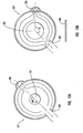
Figure 6A , where coolant enters the lower half of theshield structure 108 viainlet port hole 116A, then splits into two flows that each circulate in opposing azimuthal directions. The two flows then converge at thecavity 200, where it enters the upper half of theshield structure 108 viafluid passageways 132. With this type of setup, the flow rate of the two flows is approximately equal, and thus the rate of heat transfer is approximately equal. - However, as noted, the heat distribution within the
shield structure 108 is non-uniform. Namely, the side of the shield that is more proximate to thewindow 103 is typically subjected to higher temperatures than the opposite side. This is due to the effect imposed by the target angle on the back scattered electrons, i.e., more electrons hit the window side of theelectron collection surface 124 than the centerline side. As such, in another embodiment, the coolant flow rate is increased in that portion of the shield having a higher thermal content (i.e., the side more proximate to the window 103), which thereby increases the rate of heat removal. - In one embodiment, this is accomplished by varying the relative orientation of the
inlet port hole 116A, and/orcavity 200, with respect tofluid passageways 131. This particular arrangement is represented inFigure 6B . As is shown, an angle ∝ of less than 180 degrees is used to orient theinlet port hole 116A withfluid passageway 131 and thecavity 200 on the side proximate to thewindow 103. This decrease in relative travel distance increases the coolant flow rate, thereby increasing the convective heat transfer coefficient on that side and decreasing the shield's temperature gradient in the azimuthal direction. Consequently, the heat transfer rate on the window side is increased. Conversely, the heat transfer is decreased on the remaining side of theshield structure 108. - Increasing the rate of heat transfer can be accomplished with other approaches as well. For instance, in the side proximate to the window 103 (or whatever portion has higher thermal content), the flow area cross section of
fluid passageway 131 could be increased, and the passageway disposed in the opposite/remaining portion of the shield decreased. This would increase the volume of coolant flow through the portion of the shield having a higher thermal content, and thus increase the rate of heat transferred by convection. - It will be appreciated that the
shield assembly 117,shield structure 108, and/oraperture disk 137 may be embodied in a variety of different ways. Various features of an exemplary alternative embodiment of the shield structure are indicated inFigures 7 and 8 , where an alternative embodiment of the shield structure is indicated at 108'. As the structure and operation of this alternative embodiment of the shield structure are similar in many regards to that ofshield structure 108, no additional discussion of the common features and elements thereof is required. Any material differences between the embodiments depicted inFigures 3 and 4 , andFigures 7 ,8 and11 , respectively, such asgap 151, are addressed primarily in the context of the discussion ofFigures 9, 10 ,11, 12A, and 12B , below. - Directing attention now to
Figures 9 and 10 , shield structure 108' includes, among other things, a plurality offluid passageways 131 formed in the bottom half section of the shield structure 108'. It will be appreciated thatfluid passageways 131 can be formed directly and integrally within the body of the shield structure 108' (i.e., in the form of a hollow bore), or, as is the case with the illustrated embodiment, can be formed by defining channels with spaced apartridges - With reference now to
Figure 11 and with continuing reference toFigures 9 and 10 , additional details of an alternative embodiment of the shield assembly, indicated generally at 117', are indicated. In particular,aperture disk 137' of shield assembly 117' includes acorresponding aperture 122, as well as complementary ridges, designated at 133' and 135', that abut against theridges fluid passageways 131 when theaperture disk 137' is mated with the shield structure 108'. In the illustrated embodiment, both fluid passageways labeled as 131 are in fluid communication with one another by virtue of gaps formed incircular ridge 135, as is illustrated inFigure 11 . - Directing attention now to
Figures 12A and 12B , and with continuing attention toFigure 11 , shield assembly 117' may include means for augmenting the heat transfer capability offluid passageways 131. One exemplary structure for performing this function comprises coiled wires, designated inFigures 11 and 12B at 300 and 302, disposed withinfluid passageways 131. - The cross-sectional side view of
Figure 12B illustrates the coiled wires, or coils, 300 and 302 disposed within thefluid passageways 131, whereinfluid passageways 131 are formed when ridges 133' and 135' mate with correspondingridges Coils - Each
coil liquid coolant 114 withinfluid passageway 131. In particular, the presence ofcoils fluid passageway 131, which thereby facilitates a relative increase in the transfer of heat over what would otherwise be possible. In addition, coils 300 and 302 break up the boundary layers ofliquid coolant 114 as it passes overcoils fluid passageway 131. Disruption of the coolant boundary layer promotes turbulence in the coolant flow, and thereby improves heat transfer. Moreover, because of the gaps (shown at 139'/161'and 151'/153' inaperture disk 137' ofFigure 11 ) formed influid passageways 131,liquid coolant 114 flows both parallel and perpendicular to the axes ofcoils - It will be appreciated that other structures could be used to provide the heat transfer augmentation function performed by
coils - Various additional features of shield assembly 117' and its operation in conjunction with other components of
x-ray tube 101, with particular attention to the flow path ofliquid coolant 114, are indicated in the following discussion. - In general, and as indicated in
Figure 1 , theliquid coolant 114 is supplied to thehousing 112 via aninlet conduit 105 disposed within thehousing 112 reservoir. Theinlet conduit 105 is connected to a manifold inlet/outlet connection 118 that is affixed, or formed integrally with, acoolant manifold 116 that is disposed on, or formed as an integral part of, thecan 107 of thex-ray tube 101. Thecoolant manifold 116 forms a fluid communication path between theinlet conduit 105 and the fluid passageways 131 (not shown) via an inlet port hole formed in the manifold (not shown). - In particular, fluid communication between
inlet conduit 105 andfluid passageways 131 is achieved by orienting the shield structure 108' within thecoolant manifold 116 such that agap 151/151' (seeFigure 11 ) formed in abuttingridges 133/133' (seeFigures 11 and 12B ) is aligned with the inlet port hole (not shown) so as to receive incomingliquid coolant 114 frominlet conduit 105. Coolant is thus allowed to flow intopassageways 131. As the coolant entersfluid passageway 131, it splits into two flows, where each flow circulates in opposing azimuthal directions, as suggested inFigures 13A and 13B . Of course, as the coolant proceeds throughfluid passageway 131, heat is transferred toliquid coolant 114 from the shield structure 108'. - The flow of coolant through shield structure 108' is not necessarily restricted to
fluid passageways 131 however. In the illustrated embodiment,fluid passageway 131 is further placed in fluid communication withfluid passageway 132. As indicated inFigure 9 , this is accomplished by providing anothergap 153 inridge 133 at a point substantiallyopposite gap 151, as well as providing a corresponding gap 153' inaperture disk 137' substantially opposite gap 151'. - As indicated in
Figures 13A and 13B , a cavity, designated generally at 200, is defined within the interior wall ofrecess 155.Cavity 200 is aligned withgap 153, and is sufficiently large as to facilitate fluid communication betweenfluid passageway 131 and at least one offluid passageways 132. Thus, in this example embodiment, two coolant flows proceed throughfluid passageway 131 and then converge at the opposite side of the shield structure 108'. Theliquid coolant 114 then continues to flow into thecavity 200 viagap 153/153', and then into the upper half of the shield structure 108' viafluid passageways 132. Again, the coolant splits and the two flows traverse the upper half of the shield structure 108'. Also, as in the lower half, the coolant is heated as it flows over the shield structure 108' and cooling surfaces 126. - With continuing reference to
Figure 1 , the two flows of coolant traverse the upper half of shield structure 108', converge, and then exit at an outlet port hole (not shown) formed in manifold inlet/outlet connection 118 and in fluid communication withfluid passageway 132.Outlet fluid conduit 120 is in fluid communication with the reservoir, as is indicated by the fluid flow line. - Reference is now made to
Figure 14 , which illustrates a presently preferred embodiment of a cooling system. It will be appreciated that any of the embodiments of the shield structure discussed or contemplated herein may be profitably employed in conjunction with this cooling system. - As suggested in
Figure 14 , thecoolant manifold 116 operates in conjunction with coolingfins 110 to facilitate an enhanced convective cooling ofshield assembly 117, and thus, of thex-ray tube device 100 as a whole. Specifically, a coolant flow is generated by a heat exchanger/cooling unit 134 as previously described, and coolant flows throughinlet conduit 105, into thecoolant manifold 116, and intofluid passageways - However, instead of discharging the coolant directly into the reservoir as described in
Figure 1 , theoutlet fluid conduit 120 is connected to a flow diverter, designated at 128, which splits the coolant into two discharge streams. One of the coolant streams from theflow diverter 128 is discharged to thereservoir 112 through coolant outlet port 138 (or, optionally, into another manifold where it can be directed to other areas of the x-ray tube, as previously noted). The other coolant stream from theflow diverter 128 is discharged throughcoolant outlet port 130 and the flow is specifically directed across coolingfins 110. This directed flow more efficiently removes heat from the coolingfins 110. As inFigure 1 , the coolant eventually exits the reservoir at thereservoir discharge connection 136 and flows back to the heat exchanger/cooling unit 134 to repeat the cycle. - The embodiment of the cooling system illustrated in
Figure 14 enhances cooling of the x-ray tube by: i) providingcooling fins 110 to increase the surface area of the x-ray tube, and in particular theshield structure 108, thereby increasing the rate of convective heat transfer from the x-ray tube structures to the reservoir coolant; ii) directing a portion of the manifold coolant discharge across the fins to increase convective heat transfer from the fins, thus augmenting the convective cooling effect of the fins; and iii) convectively cooling the interior of the shield structure. The combined effect of the fluid passageways, external fins, and dual discharge manifold is to significantly increase the rate at which heat is removed from the x-ray tube. The enhanced heat transfer rate serves to reduce x-ray tube operating temperatures and thus the resultant thermal mechanical stresses, and substantially prevents thermal breakdown of the coolant, thereby extending the life of the coolant and, accordingly, the x-ray tube. - It will be appreciated that while the aforementioned preferred embodiment teaches a dual outlet flow diverter, it should be recognized that a flow diverter with multiple outlets could be utilized. Accordingly, an x-ray tube cooling system employing a multiple outlet (i.e., greater than two) flow diverter is contemplated as being within the scope of the present invention.
- As noted above, the excessive temperatures present in the area of the shield and aperture disk assembly cause mechanical stresses that can be especially problematic in areas where two components are attached. These areas are often the most subject to failure. As such, embodiments of the present system are directed to addressing this problem, especially where the
shield structure 108 and theaperture disk 137 to thecan 107. In particular, an improved braze joint configuration between theaperture disk 137 and thecan 107 is provided. Instead of providing ajoint that is brazed only on a horizontal surface, as is common in the prior art, the aperture disk is brazed to the can on both a horizontal as well as a vertical surface. Preferred embodiments of this brazing arrangement are shown inFigures 15 and 16 , to which reference is now made. -
Figure 15 is a simplified view of acathode cylinder 102 affixed to ashield structure 108 andaperture disk 137, which is in turn affixed tocan 107.Figure 16 is a section view taken along lines 16-16 inFigure 15 , which illustrates one presently preferred embodiment of the braze joint between thecan 107 and theaperture disk 137. As is shown, theaperture disk 137 includes ashoulder region 350 that projects outwardly around theaperture disk 137 periphery. The can 107 includes a correspondingly shapedshoulder region 352 that mates with that of theaperture disk 137. In particular, it is shown how the two shoulder regions together form a horizontal mating region at 402, as well as avertical mating region 400. These two regions can be brazed together. The arrangement is particularly advantageous in that it decreases the stresses between theaperture disk 137 and thecan 107 by factors of six or more in preferred embodiments, when compared to joint arrangements having a braze only along a horizontal surface. As such, the improved braze joint better resists stresses associated with the extreme temperatures of the x-ray tube, resulting in a device that is less subject to failure and that provides a longer overall operational life. - The present invention may be embodied in other specific forms without departing from its spirit or essential characteristics. The described embodiments are to be considered in all respects only as illustrative and not restrictive. The scope of the invention is, therefore, indicated by the appended claims rather than by the foregoing description.
Claims (21)
- An x-ray tube comprising:(a) an evacuated housing (107) having an electron source (106) and anode (104) disposed therein, the anode having a target surface capable of receiving electrons emitted by the electron source;(b) a shield structure (108) positioned between the electron source (106) and the anode (104), the shield structure defining an aperture (122) through which electrons are passed from the electron source to the target surface;(c) at least one fluid passageway (131, 132) disposed proximate to the shield structure (108), so that at least some heat from the shield structure is absorbed by a coolant (114) as the coolant passes through the at least one fluid passageway, and having means for facilitating nucleate boiling of the coolant flowing through the fluid passageway (111A-B, 113A-B, 115A-B); and
the x-ray tube characterized by:(d) a plurality of extended surfaces (110) disposed on an outer surface of the shield structure (108), the plurality of extended surfaces being oriented so that at least a portion of the coolant exiting the at least one fluid passageway (131, 132) is directed towards the extended surfaces. - The x-ray tube according to Claim 1, wherein the means for facilitating nucleate boiling comprises a plurality of extended surfaces (111A, 113A, 115A) being at least partially in contact with the coolant passing through the at least one fluid passageway (131, 132).
- The x-ray tube according to Claim 1, further comprising an aperture disk (137) that cooperates with the shield structure (108) to at least partially define the at least one fluid passageway (131).
- The x-ray tube according to Claim 1, further comprising an aperture disk (137) that cooperates with the shield structure (108) to at least partially define the at least one fluid passageway (131) wherein a surface of the aperture disk at least partially defines the means for facilitating nucleate boiling.
- The x-ray tube according to Claim 1, wherein the means for facilitating nucleate boiling comprises at least one microgroove (111B, 113B, 115B).
- The x-ray tube according to Claim 5, wherein the at least one microgroove (111B, 113B, 115B) has a substantially "V" shaped cross section.
- The x-ray tube according to Claim 1, wherein the at least one fluid passageway (131, 132) permits coolant (114) to flow through a first section and a second section of the shield structure (108), and in a manner so that heat is transferred away from the first section at a greater rate than in the second section.
- The x-ray tube according to Claim 1, wherein the shield structure (108) is affixed to the x-ray tube housing (116) with a braze material placed along a joint formed along both a horizontal and a vertical surface of the shield structure and the x-ray tube housing.
- The x-ray tube according to Claim 1, further comprising a fluid flow conduit (130) that directs at least a portion of the coolant (114) that has passed through the at least one fluid passageway (131, 132) directly across at least a portion of the plurality of extended surfaces (110) disposed on the shield structure (108) so that heat is transferred from the extended surfaces to the directed coolant.
- The x-ray tube according to Claim 1, wherein the shield structure (108) is comprised of an aluminum oxide dispersion strengthened copper alloy.
- The x-ray tube according to Claim 1, wherein the at least one fluid passageway (131, 132) is formed as a fluid passageway that defines at least two fluid pathways within a bottom section of the shield structure (108).
- The x-ray tube according to Claim 11, wherein the two fluid pathways are formed by matingly attaching a main body portion (108) of the shield structure to an aperture disk (137).
- The x-ray tube according to Claim 1, wherein the at least one fluid passageway (131, 132) is formed between adjacent heat dissipation elements (126) formed about an outer periphery of the shield structure when the shield structure is operably affixed to the x-ray tube housing (116).
- The x-ray tube according to Claim 1, wherein the at least one fluid passageway comprises at least one fluid passageway (131) formed within a bottom section of the shield structure (108), and at least one fluid passageway (132) formed within a side of the shield structure.
- The x-ray tube according to Claim 14, wherein the fluid passageway (131) formed within the bottom section of the shield structure, and the fluid passageway (132) formed within the side of the shield structure (108) are in fluid communication with each other.
- An x-ray tube according to Claim 1, further comprising a reservoir containing coolant (114) that is continuously circulated through the reservoir by an external cooling unit (134), the evacuated housing (107) being at least partially disposed within the reservoir.
- An x-ray tube according to Claim 1, further comprising a coolant manifold (116) having an inlet (116A) and an outlet port (116B), the inlet port receiving coolant from a cooling unit (134), wherein the at least one fluid passageway receives coolant from the inlet port and discharges the coolant at the outlet port.
- The x-ray tube according to Claim 7, wherein the length of the fluid passageway (131, 132) in the first section is relatively shorter in length than the fluid passageway of the second section so that the rate of fluid flow through the first section is relatively greater than rate of fluid flow through the second section.
- The x-ray tube cooling system according to Claim 7, wherein the cross sectional flow area of the fluid passageway in the first section is greater than the cross sectional flow area of the fluid passageway in the second section so that the rate of fluid flow through the first section is relatively greater than the rate of fluid flow through the second section.
- A method for cooling an x-ray tube, the method comprising the following steps of:(a) providing at least a first fluid path and a second fluid path through a corresponding fluid passageway (131, 132) defined within a shield structure (108) that is disposed between an electron source (106) and an anode (104);(b) directing a liquid coolant (114) through an inlet (116A) to the first and the second fluid paths;(c) causing nucleate boiling of at least a portion of the liquid coolant in the fluid passageway (131, 132);(d) discharging the liquid coolant from an outlet (116B) connected to the first and the second fluid paths;(e) directing at least a portion of the discharged liquid coolant across a plurality of extended fin surfaces (110) formed on an outside surface of the shield structure (108);(f) circulating the liquid coolant through a cooling unit (134); and(g) repeating steps (b) through (f).
- The method according to claim 20, wherein the rate of liquid coolant flow through the first fluid path is greater than the rate of liquid coolant flow through the second fluid path.
Applications Claiming Priority (3)
| Application Number | Priority Date | Filing Date | Title |
|---|---|---|---|
| US656076 | 2000-09-06 | ||
| US09/656,076 US6519318B1 (en) | 1999-07-12 | 2000-09-07 | Large surface area x-ray tube shield structure |
| PCT/US2001/025243 WO2002027751A1 (en) | 2000-09-06 | 2001-08-10 | Large surface area x-ray tube shield structure |
Publications (3)
| Publication Number | Publication Date |
|---|---|
| EP1316103A1 EP1316103A1 (en) | 2003-06-04 |
| EP1316103A4 EP1316103A4 (en) | 2003-06-25 |
| EP1316103B1 true EP1316103B1 (en) | 2010-03-24 |
Family
ID=24631512
Family Applications (1)
| Application Number | Title | Priority Date | Filing Date |
|---|---|---|---|
| EP01963934A Expired - Lifetime EP1316103B1 (en) | 2000-09-07 | 2001-08-10 | Large surface area x-ray tube shield structure |
Country Status (7)
| Country | Link |
|---|---|
| US (1) | US6519318B1 (en) |
| EP (1) | EP1316103B1 (en) |
| JP (1) | JP3857983B2 (en) |
| AT (1) | ATE462196T1 (en) |
| AU (1) | AU2001284845A1 (en) |
| DE (1) | DE60141637D1 (en) |
| WO (1) | WO2002027751A1 (en) |
Families Citing this family (22)
| Publication number | Priority date | Publication date | Assignee | Title |
|---|---|---|---|---|
| JP5237636B2 (en) * | 2004-06-30 | 2013-07-17 | コーニンクレッカ フィリップス エレクトロニクス エヌ ヴィ | X-ray tube cooling system |
| US7201514B2 (en) * | 2004-09-29 | 2007-04-10 | Varian Medical Systems Technologies, Inc. | Fluid connection assembly for x-ray device |
| US7486774B2 (en) * | 2005-05-25 | 2009-02-03 | Varian Medical Systems, Inc. | Removable aperture cooling structure for an X-ray tube |
| US7668298B2 (en) * | 2005-12-20 | 2010-02-23 | General Electric Co. | System and method for collecting backscattered electrons in an x-ray tube |
| US7359486B2 (en) * | 2005-12-20 | 2008-04-15 | General Electric Co. | Structure for collecting scattered electrons |
| US20080095317A1 (en) * | 2006-10-17 | 2008-04-24 | General Electric Company | Method and apparatus for focusing and deflecting the electron beam of an x-ray device |
| US20080112540A1 (en) * | 2006-11-09 | 2008-05-15 | General Electric Company | Shield assembly apparatus for an x-ray device |
| US7410296B2 (en) * | 2006-11-09 | 2008-08-12 | General Electric Company | Electron absorption apparatus for an x-ray device |
| US8000450B2 (en) * | 2007-09-25 | 2011-08-16 | Varian Medical Systems, Inc. | Aperture shield incorporating refractory materials |
| EP2235733B1 (en) * | 2007-12-19 | 2013-05-15 | Philips Intellectual Property & Standards GmbH | Scattered electron collector |
| US7881436B2 (en) * | 2008-05-12 | 2011-02-01 | General Electric Company | Method and apparatus of differential pumping in an x-ray tube |
| US8130910B2 (en) * | 2009-08-14 | 2012-03-06 | Varian Medical Systems, Inc. | Liquid-cooled aperture body in an x-ray tube |
| DE102009037724B4 (en) * | 2009-08-17 | 2011-09-15 | Siemens Aktiengesellschaft | X-ray |
| US8867706B2 (en) * | 2010-11-09 | 2014-10-21 | Varian Medical Systems, Inc. | Asymmetric x-ray tube |
| JP5711007B2 (en) * | 2011-03-02 | 2015-04-30 | 浜松ホトニクス株式会社 | Cooling structure for open X-ray source and open X-ray source |
| US9530528B2 (en) | 2011-12-16 | 2016-12-27 | Varian Medical Systems, Inc. | X-ray tube aperture having expansion joints |
| US9514911B2 (en) | 2012-02-01 | 2016-12-06 | Varian Medical Systems, Inc. | X-ray tube aperture body with shielded vacuum wall |
| JP2013218933A (en) * | 2012-04-10 | 2013-10-24 | Canon Inc | Micro focus x-ray generator and radiography device |
| CN111033674B (en) | 2017-08-31 | 2022-09-30 | 上海联影医疗科技股份有限公司 | Radiation emitting device |
| DE102017217181B3 (en) * | 2017-09-27 | 2018-10-11 | Siemens Healthcare Gmbh | Steh anode for an X-ray source and X-ray source |
| JP7048396B2 (en) * | 2018-04-12 | 2022-04-05 | 浜松ホトニクス株式会社 | X-ray tube |
| CN115206755A (en) * | 2021-04-14 | 2022-10-18 | 上海超群检测科技股份有限公司 | X-ray tube with self-shielding function and manufacturing method thereof |
Family Cites Families (13)
| Publication number | Priority date | Publication date | Assignee | Title |
|---|---|---|---|---|
| GB1527813A (en) | 1976-06-02 | 1978-10-11 | Emi Ltd | Cooling x-ray apparatus |
| US4622687A (en) * | 1981-04-02 | 1986-11-11 | Arthur H. Iversen | Liquid cooled anode x-ray tubes |
| US4709559A (en) | 1985-08-01 | 1987-12-01 | Siemens Aktiengesellschaft | Cooling system for relatively movable components |
| US5018181A (en) | 1987-06-02 | 1991-05-21 | Coriolis Corporation | Liquid cooled rotating anodes |
| US5541975A (en) * | 1994-01-07 | 1996-07-30 | Anderson; Weston A. | X-ray tube having rotary anode cooled with high thermal conductivity fluid |
| US5737387A (en) | 1994-03-11 | 1998-04-07 | Arch Development Corporation | Cooling for a rotating anode X-ray tube |
| US5689542A (en) * | 1996-06-06 | 1997-11-18 | Varian Associates, Inc. | X-ray generating apparatus with a heat transfer device |
| US6115454A (en) * | 1997-08-06 | 2000-09-05 | Varian Medical Systems, Inc. | High-performance X-ray generating apparatus with improved cooling system |
| US6125169A (en) | 1997-12-19 | 2000-09-26 | Picker International, Inc. | Target integral heat shield for x-ray tubes |
| US6002745A (en) | 1998-06-04 | 1999-12-14 | Varian Medical Systems, Inc. | X-ray tube target assembly with integral heat shields |
| US6074092A (en) | 1998-09-28 | 2000-06-13 | Varian Medical Systems, Inc. | Cooling system for an x-ray source |
| US6252934B1 (en) * | 1999-03-09 | 2001-06-26 | Teledyne Technologies Incorporated | Apparatus and method for cooling a structure using boiling fluid |
| US6366642B1 (en) * | 2001-01-16 | 2002-04-02 | Varian Medical Systems, Inc. | X-ray tube cooling system |
-
2000
- 2000-09-07 US US09/656,076 patent/US6519318B1/en not_active Expired - Lifetime
-
2001
- 2001-08-10 DE DE60141637T patent/DE60141637D1/en not_active Expired - Lifetime
- 2001-08-10 WO PCT/US2001/025243 patent/WO2002027751A1/en not_active Ceased
- 2001-08-10 AT AT01963934T patent/ATE462196T1/en not_active IP Right Cessation
- 2001-08-10 AU AU2001284845A patent/AU2001284845A1/en not_active Abandoned
- 2001-08-10 JP JP2002531451A patent/JP3857983B2/en not_active Expired - Lifetime
- 2001-08-10 EP EP01963934A patent/EP1316103B1/en not_active Expired - Lifetime
Also Published As
| Publication number | Publication date |
|---|---|
| WO2002027751A1 (en) | 2002-04-04 |
| JP2004510304A (en) | 2004-04-02 |
| US6519318B1 (en) | 2003-02-11 |
| ATE462196T1 (en) | 2010-04-15 |
| EP1316103A1 (en) | 2003-06-04 |
| EP1316103A4 (en) | 2003-06-25 |
| JP3857983B2 (en) | 2006-12-13 |
| AU2001284845A1 (en) | 2002-04-08 |
| DE60141637D1 (en) | 2010-05-06 |
Similar Documents
| Publication | Publication Date | Title |
|---|---|---|
| EP1234320B1 (en) | X-ray tube cooling system | |
| US6519318B1 (en) | Large surface area x-ray tube shield structure | |
| US6115454A (en) | High-performance X-ray generating apparatus with improved cooling system | |
| JP3988167B2 (en) | X-ray generator having heat transfer device | |
| US6215852B1 (en) | Thermal energy storage and transfer assembly | |
| US6307916B1 (en) | Heat pipe assisted cooling of rotating anode x-ray tubes | |
| US6477231B2 (en) | Thermal energy transfer device and x-ray tubes and x-ray systems incorporating same | |
| US6438208B1 (en) | Large surface area x-ray tube window and window cooling plenum | |
| US20090080617A1 (en) | Aperture shield incorporating refractory materials | |
| US7042981B2 (en) | X-ray tube window and surrounding enclosure cooling apparatuses | |
| KR101150778B1 (en) | X-ray tube device of industrial CT equipment | |
| US6980628B2 (en) | Electron collector system | |
| US6252937B1 (en) | High thermal performance cathode via heat pipes | |
| US20180151324A1 (en) | Heat sink for x-ray tube anode | |
| US6778635B1 (en) | X-ray tube cooling system |
Legal Events
| Date | Code | Title | Description |
|---|---|---|---|
| PUAI | Public reference made under article 153(3) epc to a published international application that has entered the european phase |
Free format text: ORIGINAL CODE: 0009012 |
|
| 17P | Request for examination filed |
Effective date: 20020514 |
|
| AK | Designated contracting states |
Designated state(s): AT BE CH CY DE DK ES FI FR GB GR IE IT LI LU MC NL PT SE TR |
|
| AX | Request for extension of the european patent |
Extension state: AL LT LV MK RO SI |
|
| A4 | Supplementary search report drawn up and despatched |
Effective date: 20030513 |
|
| RIC1 | Information provided on ipc code assigned before grant |
Ipc: 7H 05G 1/04 B Ipc: 7H 01J 35/10 A |
|
| RAP1 | Party data changed (applicant data changed or rights of an application transferred) |
Owner name: VARIAN MEDICAL SYSTEMS TECHNOLOGIES, INC. |
|
| 17Q | First examination report despatched |
Effective date: 20070808 |
|
| RAP1 | Party data changed (applicant data changed or rights of an application transferred) |
Owner name: VARIAN MEDICAL SYSTEMS, INC. |
|
| GRAP | Despatch of communication of intention to grant a patent |
Free format text: ORIGINAL CODE: EPIDOSNIGR1 |
|
| GRAC | Information related to communication of intention to grant a patent modified |
Free format text: ORIGINAL CODE: EPIDOSCIGR1 |
|
| GRAS | Grant fee paid |
Free format text: ORIGINAL CODE: EPIDOSNIGR3 |
|
| GRAA | (expected) grant |
Free format text: ORIGINAL CODE: 0009210 |
|
| AK | Designated contracting states |
Kind code of ref document: B1 Designated state(s): AT BE CH CY DE DK ES FI FR GB GR IE IT LI LU MC NL PT SE TR |
|
| AX | Request for extension of the european patent |
Extension state: AL LT LV MK RO SI |
|
| REG | Reference to a national code |
Ref country code: GB Ref legal event code: FG4D |
|
| REG | Reference to a national code |
Ref country code: CH Ref legal event code: EP |
|
| REG | Reference to a national code |
Ref country code: NL Ref legal event code: T3 |
|
| REG | Reference to a national code |
Ref country code: IE Ref legal event code: FG4D |
|
| REF | Corresponds to: |
Ref document number: 60141637 Country of ref document: DE Date of ref document: 20100506 Kind code of ref document: P |
|
| LTIE | Lt: invalidation of european patent or patent extension |
Effective date: 20100324 |
|
| PG25 | Lapsed in a contracting state [announced via postgrant information from national office to epo] |
Ref country code: AT Free format text: LAPSE BECAUSE OF FAILURE TO SUBMIT A TRANSLATION OF THE DESCRIPTION OR TO PAY THE FEE WITHIN THE PRESCRIBED TIME-LIMIT Effective date: 20100324 Ref country code: FI Free format text: LAPSE BECAUSE OF FAILURE TO SUBMIT A TRANSLATION OF THE DESCRIPTION OR TO PAY THE FEE WITHIN THE PRESCRIBED TIME-LIMIT Effective date: 20100324 |
|
| PG25 | Lapsed in a contracting state [announced via postgrant information from national office to epo] |
Ref country code: GR Free format text: LAPSE BECAUSE OF FAILURE TO SUBMIT A TRANSLATION OF THE DESCRIPTION OR TO PAY THE FEE WITHIN THE PRESCRIBED TIME-LIMIT Effective date: 20100625 Ref country code: BE Free format text: LAPSE BECAUSE OF FAILURE TO SUBMIT A TRANSLATION OF THE DESCRIPTION OR TO PAY THE FEE WITHIN THE PRESCRIBED TIME-LIMIT Effective date: 20100324 Ref country code: ES Free format text: LAPSE BECAUSE OF FAILURE TO SUBMIT A TRANSLATION OF THE DESCRIPTION OR TO PAY THE FEE WITHIN THE PRESCRIBED TIME-LIMIT Effective date: 20100705 Ref country code: SE Free format text: LAPSE BECAUSE OF FAILURE TO SUBMIT A TRANSLATION OF THE DESCRIPTION OR TO PAY THE FEE WITHIN THE PRESCRIBED TIME-LIMIT Effective date: 20100324 |
|
| PLBE | No opposition filed within time limit |
Free format text: ORIGINAL CODE: 0009261 |
|
| STAA | Information on the status of an ep patent application or granted ep patent |
Free format text: STATUS: NO OPPOSITION FILED WITHIN TIME LIMIT |
|
| PG25 | Lapsed in a contracting state [announced via postgrant information from national office to epo] |
Ref country code: PT Free format text: LAPSE BECAUSE OF FAILURE TO SUBMIT A TRANSLATION OF THE DESCRIPTION OR TO PAY THE FEE WITHIN THE PRESCRIBED TIME-LIMIT Effective date: 20100726 Ref country code: DK Free format text: LAPSE BECAUSE OF FAILURE TO SUBMIT A TRANSLATION OF THE DESCRIPTION OR TO PAY THE FEE WITHIN THE PRESCRIBED TIME-LIMIT Effective date: 20100324 |
|
| 26N | No opposition filed |
Effective date: 20101228 |
|
| PG25 | Lapsed in a contracting state [announced via postgrant information from national office to epo] |
Ref country code: IT Free format text: LAPSE BECAUSE OF FAILURE TO SUBMIT A TRANSLATION OF THE DESCRIPTION OR TO PAY THE FEE WITHIN THE PRESCRIBED TIME-LIMIT Effective date: 20100324 Ref country code: MC Free format text: LAPSE BECAUSE OF NON-PAYMENT OF DUE FEES Effective date: 20100831 |
|
| REG | Reference to a national code |
Ref country code: CH Ref legal event code: PL |
|
| GBPC | Gb: european patent ceased through non-payment of renewal fee |
Effective date: 20100810 |
|
| PG25 | Lapsed in a contracting state [announced via postgrant information from national office to epo] |
Ref country code: CH Free format text: LAPSE BECAUSE OF NON-PAYMENT OF DUE FEES Effective date: 20100831 Ref country code: LI Free format text: LAPSE BECAUSE OF NON-PAYMENT OF DUE FEES Effective date: 20100831 |
|
| REG | Reference to a national code |
Ref country code: FR Ref legal event code: ST Effective date: 20110502 |
|
| PG25 | Lapsed in a contracting state [announced via postgrant information from national office to epo] |
Ref country code: IE Free format text: LAPSE BECAUSE OF NON-PAYMENT OF DUE FEES Effective date: 20100810 Ref country code: FR Free format text: LAPSE BECAUSE OF NON-PAYMENT OF DUE FEES Effective date: 20100831 |
|
| PG25 | Lapsed in a contracting state [announced via postgrant information from national office to epo] |
Ref country code: GB Free format text: LAPSE BECAUSE OF NON-PAYMENT OF DUE FEES Effective date: 20100810 |
|
| PG25 | Lapsed in a contracting state [announced via postgrant information from national office to epo] |
Ref country code: CY Free format text: LAPSE BECAUSE OF FAILURE TO SUBMIT A TRANSLATION OF THE DESCRIPTION OR TO PAY THE FEE WITHIN THE PRESCRIBED TIME-LIMIT Effective date: 20100324 |
|
| PG25 | Lapsed in a contracting state [announced via postgrant information from national office to epo] |
Ref country code: LU Free format text: LAPSE BECAUSE OF NON-PAYMENT OF DUE FEES Effective date: 20100810 |
|
| PG25 | Lapsed in a contracting state [announced via postgrant information from national office to epo] |
Ref country code: TR Free format text: LAPSE BECAUSE OF FAILURE TO SUBMIT A TRANSLATION OF THE DESCRIPTION OR TO PAY THE FEE WITHIN THE PRESCRIBED TIME-LIMIT Effective date: 20100324 |
|
| PGFP | Annual fee paid to national office [announced via postgrant information from national office to epo] |
Ref country code: NL Payment date: 20150826 Year of fee payment: 15 |
|
| REG | Reference to a national code |
Ref country code: NL Ref legal event code: MM Effective date: 20160901 |
|
| REG | Reference to a national code |
Ref country code: DE Ref legal event code: R081 Ref document number: 60141637 Country of ref document: DE Owner name: VAREX IMAGING CORPORATION (N.D.GES. DES STAATE, US Free format text: FORMER OWNER: VARIAN MEDICAL SYSTEMS, INC., PALO ALTO, CALIF., US |
|
| PG25 | Lapsed in a contracting state [announced via postgrant information from national office to epo] |
Ref country code: NL Free format text: LAPSE BECAUSE OF NON-PAYMENT OF DUE FEES Effective date: 20160901 |
|
| PGFP | Annual fee paid to national office [announced via postgrant information from national office to epo] |
Ref country code: DE Payment date: 20200721 Year of fee payment: 20 |
|
| REG | Reference to a national code |
Ref country code: DE Ref legal event code: R071 Ref document number: 60141637 Country of ref document: DE |