EP1315364A2 - Illuminating a scan region - Google Patents
Illuminating a scan region Download PDFInfo
- Publication number
- EP1315364A2 EP1315364A2 EP02257889A EP02257889A EP1315364A2 EP 1315364 A2 EP1315364 A2 EP 1315364A2 EP 02257889 A EP02257889 A EP 02257889A EP 02257889 A EP02257889 A EP 02257889A EP 1315364 A2 EP1315364 A2 EP 1315364A2
- Authority
- EP
- European Patent Office
- Prior art keywords
- reflector
- exit aperture
- hollow reflector
- illumination system
- reflectors
- Prior art date
- Legal status (The legal status is an assumption and is not a legal conclusion. Google has not performed a legal analysis and makes no representation as to the accuracy of the status listed.)
- Granted
Links
Images


Classifications
-
- H—ELECTRICITY
- H04—ELECTRIC COMMUNICATION TECHNIQUE
- H04N—PICTORIAL COMMUNICATION, e.g. TELEVISION
- H04N1/00—Scanning, transmission or reproduction of documents or the like, e.g. facsimile transmission; Details thereof
- H04N1/024—Details of scanning heads ; Means for illuminating the original
- H04N1/028—Details of scanning heads ; Means for illuminating the original for picture information pick-up
- H04N1/02815—Means for illuminating the original, not specific to a particular type of pick-up head
- H04N1/02845—Means for illuminating the original, not specific to a particular type of pick-up head using an elongated light source, e.g. tubular lamp, LED array
- H04N1/0285—Means for illuminating the original, not specific to a particular type of pick-up head using an elongated light source, e.g. tubular lamp, LED array in combination with at least one reflector which is in fixed relation to the light source
-
- H—ELECTRICITY
- H04—ELECTRIC COMMUNICATION TECHNIQUE
- H04N—PICTORIAL COMMUNICATION, e.g. TELEVISION
- H04N1/00—Scanning, transmission or reproduction of documents or the like, e.g. facsimile transmission; Details thereof
- H04N1/024—Details of scanning heads ; Means for illuminating the original
- H04N1/028—Details of scanning heads ; Means for illuminating the original for picture information pick-up
- H04N1/02815—Means for illuminating the original, not specific to a particular type of pick-up head
-
- H—ELECTRICITY
- H04—ELECTRIC COMMUNICATION TECHNIQUE
- H04N—PICTORIAL COMMUNICATION, e.g. TELEVISION
- H04N1/00—Scanning, transmission or reproduction of documents or the like, e.g. facsimile transmission; Details thereof
- H04N1/024—Details of scanning heads ; Means for illuminating the original
- H04N1/028—Details of scanning heads ; Means for illuminating the original for picture information pick-up
- H04N1/02815—Means for illuminating the original, not specific to a particular type of pick-up head
- H04N1/02845—Means for illuminating the original, not specific to a particular type of pick-up head using an elongated light source, e.g. tubular lamp, LED array
- H04N1/0286—Means for illuminating the original, not specific to a particular type of pick-up head using an elongated light source, e.g. tubular lamp, LED array in combination with a light integrating, concentrating or defusing cavity
-
- H—ELECTRICITY
- H04—ELECTRIC COMMUNICATION TECHNIQUE
- H04N—PICTORIAL COMMUNICATION, e.g. TELEVISION
- H04N1/00—Scanning, transmission or reproduction of documents or the like, e.g. facsimile transmission; Details thereof
- H04N1/024—Details of scanning heads ; Means for illuminating the original
- H04N1/028—Details of scanning heads ; Means for illuminating the original for picture information pick-up
- H04N1/02815—Means for illuminating the original, not specific to a particular type of pick-up head
- H04N1/02845—Means for illuminating the original, not specific to a particular type of pick-up head using an elongated light source, e.g. tubular lamp, LED array
- H04N1/0287—Means for illuminating the original, not specific to a particular type of pick-up head using an elongated light source, e.g. tubular lamp, LED array using a tubular lamp or a combination of such lamps
-
- H—ELECTRICITY
- H04—ELECTRIC COMMUNICATION TECHNIQUE
- H04N—PICTORIAL COMMUNICATION, e.g. TELEVISION
- H04N1/00—Scanning, transmission or reproduction of documents or the like, e.g. facsimile transmission; Details thereof
- H04N1/024—Details of scanning heads ; Means for illuminating the original
- H04N1/028—Details of scanning heads ; Means for illuminating the original for picture information pick-up
- H04N1/02815—Means for illuminating the original, not specific to a particular type of pick-up head
- H04N1/02885—Means for compensating spatially uneven illumination, e.g. an aperture arrangement
- H04N1/0289—Light diffusing elements, e.g. plates or filters
-
- H—ELECTRICITY
- H04—ELECTRIC COMMUNICATION TECHNIQUE
- H04N—PICTORIAL COMMUNICATION, e.g. TELEVISION
- H04N1/00—Scanning, transmission or reproduction of documents or the like, e.g. facsimile transmission; Details thereof
- H04N1/04—Scanning arrangements, i.e. arrangements for the displacement of active reading or reproducing elements relative to the original or reproducing medium, or vice versa
- H04N1/10—Scanning arrangements, i.e. arrangements for the displacement of active reading or reproducing elements relative to the original or reproducing medium, or vice versa using flat picture-bearing surfaces
- H04N1/1013—Scanning arrangements, i.e. arrangements for the displacement of active reading or reproducing elements relative to the original or reproducing medium, or vice versa using flat picture-bearing surfaces with sub-scanning by translatory movement of at least a part of the main-scanning components
- H04N1/1017—Scanning arrangements, i.e. arrangements for the displacement of active reading or reproducing elements relative to the original or reproducing medium, or vice versa using flat picture-bearing surfaces with sub-scanning by translatory movement of at least a part of the main-scanning components the main-scanning components remaining positionally invariant with respect to one another in the sub-scanning direction
-
- H—ELECTRICITY
- H04—ELECTRIC COMMUNICATION TECHNIQUE
- H04N—PICTORIAL COMMUNICATION, e.g. TELEVISION
- H04N1/00—Scanning, transmission or reproduction of documents or the like, e.g. facsimile transmission; Details thereof
- H04N1/04—Scanning arrangements, i.e. arrangements for the displacement of active reading or reproducing elements relative to the original or reproducing medium, or vice versa
- H04N1/19—Scanning arrangements, i.e. arrangements for the displacement of active reading or reproducing elements relative to the original or reproducing medium, or vice versa using multi-element arrays
- H04N1/191—Scanning arrangements, i.e. arrangements for the displacement of active reading or reproducing elements relative to the original or reproducing medium, or vice versa using multi-element arrays the array comprising a one-dimensional [1D] array
- H04N1/192—Simultaneously or substantially simultaneously scanning picture elements on one main scanning line
- H04N1/193—Simultaneously or substantially simultaneously scanning picture elements on one main scanning line using electrically scanned linear arrays, e.g. linear CCD arrays
Definitions
- This invention relates to optical scanners in general and in particular to an illumination system for illuminating a scan region on an object and more specifically to a light source assembly having improved illumination.
- Optical scanners are well-known in the art and produce machine-readable data which are representative of a scanned object, e.g. a page of printed text.
- a typical optical scanner device such as a flatbed scanner, includes illumination and/ optical systems to accomplish scanning of the object.
- the illumination system illuminates a portion of the object (commonly referred to as a "scan region"), whereas the optical system collects light reflected by the illuminated scan region and focuses a small area of the illuminated scan region (commonly referred to as a "scan line”) onto the surface of a photosensitive detector positioned within the scanner.
- Image data representative of the entire object then may be obtained by sweeping the scan line across the entire object, usually by moving the illumination and optical systems with respect to the object.
- the illumination system may include a light source (e.g., a fluorescent or incandescent lamp or an array of light emitting diodes (LEDs)).
- the optical system may include a lens and/or mirror assembly to focus the image of the illuminated scan line onto the surface of the detector.
- a "contact image sensor” CIS may be used to collect and focus light from the illuminated scan region onto the detector.
- the photosensitive detector used to detect the image light focused thereon by the optical system may be a charge-coupled device (CCD), although other devices may be used.
- CCD charge-coupled device
- a typical CCD may comprise an array of individual cells or "pixels,” each of which collects or builds-up an electrical charge in response to exposure to light. Since the quantity of the accumulated electrical charge in any given cell or pixel is related to the intensity and duration of the light exposure, a CCD may be used to detect light and dark spots of an image focused thereon.
- image light refers to the light that is focused onto the surface of the detector array by the optical system. Depending on the type of scanner and the type of document, the image light may be reflected from the document or object being scanned or it may be transmitted through the object or document.
- the image light may be converted into digital signals in three steps. First, each pixel in the CCD detector converts the light it receives into an electric charge. Second, the charges from the pixels are converted into analog voltages by an analog amplifier. Finally, the analog voltages are digitized by an analog-to-digital (A/D) converter. The digital signals then may be processed and/or stored as desired.
- A/D analog-to-digital
- the quality of the image data produced by a scanner is usually related to the quality of the illumination that is provided to the scan region. If the illumination is not sufficiently bright, the result may be excessive noise in the image data which may manifest itself as "snow." Other problems may appear if the level of illumination is not substantially uniform along the length of the scan line. In such cases, the resulting image data may be of variable quality along the length of the scan line. Extreme variations of illumination may even result in "drop outs" in the image data.
- the illumination system is to be used with a battery-powered (e.g., portable) image scanner.
- a battery-powered (e.g., portable) image scanner For example, in order to minimize the power drain on the battery, most portable image scanners are designed to provide the minimum amount of illumination commensurate with good image quality.
- such low power illumination systems provide little margin against illumination variations. Consequently, even slight variations in illumination may well result in portions of the scan line being insufficiently illuminated.
- Another problem with many illumination systems is that only a small fraction of the light produced by the light source is used to illuminate the scan region.
- An illumination system for illuminating a scan region on an object may comprise a hollow reflector having an interior reflective surface and an exit aperture.
- a light source positioned within the hollow reflector produces a plurality of light rays, some of which are reflected by the interior reflective surface of the hollow reflector before passing through the exit aperture.
- First and second reflectors are positioned adjacent respective first and second sides of the exit aperture of the hollow reflector. The first and second reflectors are positioned in non-parallel, spaced-apart relation to one another so that the first and second reflectors at least partially collimate light passing through the exit aperture of the hollow reflector to form a collimated beam.
- Also disclosed is a method for illuminating a scan region on an object that comprises the steps of: Providing a hollow reflector having an interior reflecting surface and an exit aperture; positioning a collimating reflector adjacent the exit aperture of the hollow reflector; and directing a plurality of light rays onto the interior reflecting surface of the hollow reflector, the interior reflecting surface reflecting some of the light rays through the exit aperture in the hollow reflector, the collimating reflector at least partially collimating light exiting the exit aperture in the hollow reflector to form a collimated beam.
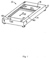
- An illumination system 10 according to the present invention is shown and described herein as it may be used in conjunction with a scanner device 12 of the type well-known in the art. As will be described in greater detail below, the illumination system 10 provides for improved illumination of an object 18 ( Figure 4) being scanned by the scanner 12.
- the scanner device 12 that may be used in conjunction with one embodiment of the illumination system 10 may comprise a generally rectangularly shaped housing 14 having a transparent platen 16 provided thereon.
- the transparent platen 16 allows the object 18 ( Figure 4), such as a sheet of paper having written text or graphics provided thereon, positioned on the transparent platen 16 to be scanned by an imaging device (not shown) provided within the housing 14 of the scanner device 12.
- the scanner device 12 produces electronic image data signals (not shown) that are representative of the scanned object 18.
- the illumination system 10 is mounted to a carriage assembly 20 that is moveably mounted within the housing 14. The arrangement is such that the carriage assembly 20, thus illumination system 10, is moveable back and forth underneath the transparent platen 16, generally along a displacement path 22.
- a carriage drive system (not shown) operatively associated with the carriage assembly 20 moves the carriage assembly 20 back and forth underneath the transparent platen 16 (i.e., along the displacement path 22) to allow the imaging device (not shown) associated with the scanner device 12 to scan the object 18 positioned on the transparent platen 16.
- the illumination system 10 may comprise a hollow reflector 24 having an interior reflective surface 26 and an exit aperture 28.
- the interior reflective surface 26 comprise a diffusing reflective surface so that light incident thereon is scattered or diffused over a wide angle.
- a light source 30, such as a flourescent lamp 32, is positioned within the hollow reflector 24 in the manner best seen in Figure 4.
- the illumination system 10 also comprises a first reflector 34 positioned adjacent a first side 36 of the exit aperture 28 of the hollow reflector 24.
- a second reflector 38 is positioned adjacent a second side 40 of the exit aperture 28 of the hollow reflector 24.
- the first and second reflectors 34 and 38 comprise specular reflecting surfaces and are positioned in generally non-parallel, spaced-apart relation so that the first and second reflectors 34 and 38 at least partially collimate light passing through the exit aperture 28 to form a collimated beam 42. See Figure 4. It should be understood that the terms "collimated” and “collimated beam” as used herein also refer to partially collimated and partially collimated beams in that the a completely collimated beam is rarely produced by any real optical system.
- the collimated beam 42 produced by the illumination system 10 illuminates a scan region 44 on the object 18 positioned adjacent the transparent platen 16, as is best seen in Figure 4.
- the imaging system (not shown) is arranged within the scanner device 12 so that the imaging system receives image light from a scan line 54 contained within the illuminated scan region 44.
- a significant advantage of the illumination system 10 according to the present invention is that it provides for improved illumination uniformity of the scan region 44, thereby generally enhancing the overall quality of the image data produced by the scanner device 12.
- the illumination system 10 also directs toward the scan region 44 a greater portion of the light rays produced by the light source 30. Consequently, the illumination system 10 allows a lower power light source to be used while providing the same illumination as other types of illumination systems utilizing higher power light sources.
- the hollow reflector 24 along with first and second reflectors 34 and 38 serve as a light baffle to reduce the amount of stray light produced by the light source 30 that may inadvertently enter the imaging system of the scanner device 12.
- the reduction in the amount of stray light entering the imaging system of the scanner device 12 tends to improve the quality of the resulting scanned image data.
- the open exit aperture 28 of the hollow reflector 24 facilitates better cooling of the light source 30. Improved cooling can be further realized by leaving open the first and second ends 60 and 62 of the hollow reflector 24.
- the various embodiments of the illumination system 10 will now be described in detail. However, before proceeding with the detailed description it should be noted that while the illumination system 10 is shown and described herein as it could be used in a flatbed scanner device 12 of the type well-known in the art, it is not limited to use with any particular type or style of imaging device. For example, the illumination system 10 could also be used in a portable or hand-held imaging or scanner device or even in a photocopier or a facsimile machine.
- the scanner device 12 is shown and described herein as it may be used to scan an object 18, such as a document with written text thereon, it is not limited to use with any particular type of object 18. Accordingly, the illumination system 10 according to the present invention should not be regarded as limited to the particular type of scanner device nor to the particular applications shown and described herein.
- a first embodiment 10 of the illumination system according to the present invention is shown in Figures 1-4 as it could be used in a scanner device 12 of the type well-known in the art. Since scanner devices are well-known in the art and represent only an illustrative example of one type of imaging device in which may be used the illumination system 10, the scanner device 12 that may be utilized with the illumination system 10 of the present invention will not be described in great detail herein. However, in order to provide a foundation for better understanding at least one application for the present invention, the scanner device 12 will be briefly described below.
- the scanner device 12 may include a generally rectangularly-shaped housing 14 having a central aperture or opening 46 therein that is sized to receive a transparent platen 16 suitable for receiving an object 18 to be scanned.
- the object 18 may comprise a document with written text or graphics provided thereon, although other objects may also be used.
- the housing 14 is also sized to receive a suitable imaging system, such as a line type scanner.
- the imaging system comprises a reflective line type scanner system of the type well-known in the scanner art having components that are mounted to a moveable carriage assembly 20.
- the moveable carriage assembly 20 is moveably mounted within the housing 14 so that the carriage assembly 20 may be moved back and forth underneath the transparent platen 16 to allow the imaging system to capture an image of the object 18 positioned on the transparent platen 16.
- the scanner device 12 may also be provided with other types of systems and devices, such as, for example, a control system, an image processing system, and a carriage drive system, that may be required or desired for the particular application.
- scanner devices such as scanner device 12
- systems and devices typically associated with such scanner devices could be readily provided by persons having ordinary skill in the art after having become familiar with the teachings of the present invention, the various systems and devices that may be required or desired in any particular scanner utilizing the illumination system 10 according to the present invention will not be described in further detail herein.
- a first embodiment of the illumination system 10 may be mounted to the carriage assembly 20 ( Figure 1) so that the illumination system 10 may be moved back and forth underneath the transparent platen 16, i.e., generally along the displacement path 22. In this way, the illumination system 10 may be used to illuminate a scan region 44 on the object 18 positioned on the transparent platen. See Figure 4. Then, as the moveable carriage 20 is moved along the displacement path 22, the illumination system 10 illuminates those portions of the object 18 being scanned by the imaging device.
- the illumination system 10 comprises a hollow reflector 24 which, in one preferred embodiment, may comprise a generally elongate body 48 having an interior wall 50 therein which defines the interior reflective surface 26 of the hollow reflector 24. It is generally preferred, but not required, that the interior wall 50 define a substantially cylindrically shaped surface. Accordingly, the interior reflective surface 26 formed by the interior wall 50 will have a substantially circular cross-section and a length 52. It is generally preferred that the length 52 of the elongate body 48 be substantially co-extensive with the length of the scan line 54 contained within the illuminated scan region 44.
- the interior wall 50 of elongate body 48 is provided with an axially-oriented opening or slot therein that defines the exit aperture 28.
- the particular location (i.e., radial position) of the axially-oriented opening or slot should be selected so that the at least partially collimated beam 42 produced by the illumination system 10 will be directed to the appropriate location on the object 18.
- the arc subtended by the axially-oriented slot that defines the exit aperture 28 should be selected so that a substantial portion of the light produced by the light source 30 and reflected by the interior reflecting surface 26 will ultimately traverse the exit aperture 28 before being absorbed by components and materials contained within the interior 58 of the hollow reflector 24.
- the arc subtended by the axially-oriented slot may be in the range of about 15• about 50• (31• preferred).
- other angles may be used depending on the requirements of the particular application, as would be obvious to persons having ordinary skill in the art after having become familiar with the teachings of the present invention.
- the exit aperture 28 of hollow reflector 24 remain open to facilitate the flow of air around the light source 30, thus assist in the cooling of the light source 30.
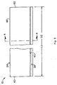
- This cooling capability can be enhanced by leaving open the ends 60 and 62 ( Figures 2 and 3) of the elongate body 48 that defines the hollow reflector 24.
- the open ends 60 and 62 provide an inlet for air to enter the interior region 58 of hollow reflector 24. After absorbing heat from the light source 30, the air will generally be discharged through the open exit aperture 28 in accordance with well-known thermal convection principles.
- semi-closed ends such as may be achieved by covering each end 60, 62 of body 48 with a louvered or perforated cover (not shown), may also be used.
- air inlet holes may be provided along the length of the interior wall 50.
- this arrangement will be generally less desirable than leaving open the ends 60 and 62, since holes or openings along the length of the interior wall 50 will generally reduce the amount of light available to illuminate the scan region 44.
- the generally elongate body 48 comprising the hollow reflector 24 may be fabricated from any of a wide range of materials, such as metals or plastics, that would be suitable for the intended application. Consequently, the present invention should not be regarded as limited to an elongate body 48 comprising any particular material. However, by way of example, in one preferred embodiment, the elongate body 48 is fabricated from aluminum.
- the light source 30 may comprise any of a wide variety of light sources that are currently available or that may be developed in the future for producing light along the length 52 of the hollow reflector 24.
- the light source 30 may comprise a flourescent lamp 32 of the type that are well-known in the art for such applications and that are readily and commercially available.
- other types of light sources such as incandescent lamps, may also be used.
- the interior reflective surface 26 of elongate body 48 comprise a diffusing reflective surface that, while reflecting a substantial amount of light incident thereon, also scatters or diffuses the incident light.
- the scattering provided by the diffusing reflective surface 26 improves the uniformity of the illumination along the length 52 of the hollow reflector 24 and also helps to smooth intensity variations that may occur along the length of the light source 30.
- the interior wall 50 of the body 48 it may be necessary or desirable to provide a diffusing reflecting coating 56 on the interior reflective surface 26 of hollow reflector 24.
- the body 48 of hollow reflector 24 comprises aluminum (which naturally provides a generally specular reflective surface)
- the interior surface 26 could be roughened (e.g., etched) to provide the diffuse reflecting characteristic.
- the diffuse reflecting characteristic is achieved by painting (i.e., coating) the interior wall 50 of the aluminum body 48 with white paint having a high reflectivity.
- the illumination system 10 may also comprise first and second reflectors 34 and 38 positioned adjacent the exit aperture 28 of the hollow reflector 24.
- the first and second reflectors 34 and 38 at least partially collimate light passing through the exit aperture 28 to form the collimated beam 42.
- the first reflector 34 is positioned adjacent the first side 36 of the exit aperture 28 of the hollow reflector 24.
- the second reflector 38 is positioned adjacent the second side 40 of the exit aperture 28.
- the first and second reflectors 34 and 38 may comprise generally planar surfaces that are positioned in generally non-parallel, spaced-apart diverging relation so that they substantially collimate light emerging from the exit aperture 28 of hollow reflector 24.
- both the first and second reflectors 34 and 38 comprise specular reflective surfaces (as opposed to the diffuse reflective surface provided on the interior reflective surface 26 of hollow reflector 24). It is also generally preferred that both the first and second reflectors 34 and 38 comprise substantially planar (i.e., flat) surfaces, although this is not required.
- each reflector 34 and 38 comprises a substantially flat or planar surface of the body 48. That is, the body 48 is suitably formed so that it comprises both the interior reflective surface 26 of the hollow reflector 24 as well as the first and second reflectors 34 and 38. It is generally preferred that the flat surfaces of body 48 that form the first and second reflectors 34 and 38 comprise specular reflecting surfaces. Such specular reflecting surfaces allow the first and second reflectors 34 and 38 to collimate the light emerging from the exit aperture 28, thus forming collimated beam 42.
- the specular reflecting characteristics to be provided by the first and second reflectors 34 and 38 may be accomplished in any of a wide variety of ways.
- the first and second reflectors 34 and 38 may comprise the natural finish of the aluminum material.
- the smoothness i.e., surface finish
- the first and second reflectors 34 and 38 may be coated with respective specular reflecting coatings 72 and 74 to provide the desired specular reflecting characteristic.
- specular reflective coatings could comprise any of a wide range of materials now known in the art or that may be developed in the future for providing such a specular reflecting characteristic. Examples of such coating materials include, but are not limited to, metallized mylar or any similar type of highly specularly reflective material.
- metal coatings may be deposited directly on the surfaces comprising the first and second reflectors 34 and 38 by any of wide range of suitable processes (e.g, chemical vapor deposition, sputtering, etc.).
- glass mirrors may be affixed to the surfaces 34 and 38.
- first and second reflectors 34 and 38 may be varied to provide the desired degree of collimation to the collimated beam 42.
- the first and second reflectors 34 and 38 may comprise planar or flat surfaces positioned in generally non-parallel, spaced-apart relation in the manner best seen in Figure 4.
- the angles 64 and 66 formed between a centerline 68 of the exit aperture 28 are preferred to provide the desired degree of collimation to the collimated beam 42 as well as to direct the collimated beam 42 to the appropriate area on the object 18.
- the centerline 68 of the exit aperture 28 extends between the first and second reflectors 34 and 38 and intercepts the central axis 70 of the cylindrical interior wall 50 of hollow reflector 24.
- the angles 64 and 66 are identical to one another and may be in the range of about 5• to about 20• (11• preferred), although other angles are possible.
- first and second reflectors 34 and 38 be joined to the respective first and second sides 36 and 40 of the exit aperture 28 so that respective sharp corners 76 and 78 (as opposed to a smooth or partially rounded transition) are formed between the first and second sides 36 and 40 of the exit aperture 28 and the respective first and second reflectors 34 and 38. See Figure 4. Generally speaking, a sharp corner minimizes scattering, thus improves the collimation of the collimated beam 42. If a smooth or rounded transition is provided between the exit aperture 28 and the first and second reflectors 34 and 38, then it will be generally preferable to provide the smooth or rounded transition with a diffusing reflective surface. As discussed above for the interior reflective surface 26 of hollow reflector 24, such a diffusing reflective surface may be provided by coating the smooth or rounded transition area with white paint or other highly reflective material.
- this program was used to model various configurations until the collimated beam 42 was substantially collimated with minimal divergence for the particular orientation, shape, and composition of the reflectors employed.
- other programs that are now available or that may be developed in the future may also be used to assist in arriving at an optimum configuration.
- the illumination system 10 may be operated as follows to provide improved illumination of the scan region 44 during the scanning process.
- a user (not shown) would set-up or initialize the scanner device 12 to perform the scanning operation by actuating the appropriate buttons or switches 43, 45 ( Figure 1) which may be provided on the scanner device 12 for this purpose.
- the need to perform such an initialization process may or may not need to be performed depending on the operating characteristics of the particular scanner device 12.
- the particular steps required to perform the set-up or initialization may vary depending on the particular scanner device. Consequently, the present invention should not be regarded as limited to performing such an initialization process and/or the specific steps required to perform the process.
- the user may place the desired object 18 to be scanned on the transparent platen 16 and thereafter initiate the scanning operation.
- the light source 30 ( Figure 4) is activated to produce light. Most of the light produced by the light source 30 is incident on the interior reflective surface 26 of the hollow reflector 24 whereupon it is reflected and diffused by the diffusing reflecting characteristic of the interior reflective surface 26. Thereafter, the reflected diffused light passes through the exit aperture 28 of hollow reflector 24. Of course, some of the light produced by the light source 30 passes directly through the exit aperture 28 and is not reflected and diffused by the interior reflective surface 26 of hollow reflector 24.
- the first and second reflectors 34 and 38 comprise specular reflecting surfaces, and since the reflectors 34 and 38 are carefully positioned and oriented to at least partially collimate the light passing through the exit aperture 28 of hollow reflector 24, the first and second reflectors 34 and 38 form the collimated beam 42 which illuminates the scan region 44 on the object 18 being scanned. Thereafter, the imaging device (not shown) associated with the scanner apparatus 12 captures image data (not shown) corresponding to the scan line 54 contained within the illuminated scan region 44. The entire object 18 may be scanned by moving the carriage assembly 20 along the displacement path 22 in any of a wide range of manners well-known in the art for such scanner devices.
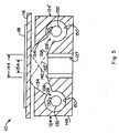
- a second embodiment 110 of the illumination system according to the present invention is illustrated in Figure 5 and may comprise two hollow reflectors 124 and 124' positioned adjacent one another. This second embodiment may be used to provide increased illumination of the scan region 144 on an object 118 provided on transparent platen 116. Alternatively, smaller (i.e., lower power) light sources may be used to provide an equivalent amount of illumination as the first embodiment 10 described above.
- the second embodiment 110 may comprise a single elongate body 148 which is shaped or formed as necessary to provide the various reflecting surfaces.
- the body 148 may be provided with a first interior wall 150 which defines a first generally cylindrical hollow reflector 124 and a second interior wall 150' that defines the second hollow reflector 124'.
- the body 148 also defines first and second exit apertures 128 and 128' for each respective hollow reflector 124 and 124'.
- the body 148 also defines first and second reflectors 134 and 138 for the first hollow reflector 124, as well as first and second reflectors 134' and 138' for the second hollow reflector 124'.
- the body 148 may be provided with an opening 127 therein positioned between the first and second hollow reflectors 124 and 124' to allow an imaging system (not shown) to image a scan line 154 contained within the illuminated scan region 144.
- Each hollow reflector 124 and 124' may be provided with a corresponding light source 130 and 130' which, in the embodiment shown and described herein, may comprise respective first and second flourescent lamps 132 and 132'.
- the geometric configurations of the various reflectors and elements comprising the second embodiment 110 of the illumination system are selected so that the partially collimated beams 142 and 142' are shaped and directed to illuminate the scan region 144.
- the shapes and relative configurations of the various reflectors and elements were optimized with the assistance of the "Advanced System Analysis Program" (ASAP) described above for the first embodiment.
- the ASAP program was used to model various configurations until the collimated beams 142 and 142' were substantially collimated with minimal divergence for the particular orientation, shape, and composition of the reflectors employed.
Landscapes
- Engineering & Computer Science (AREA)
- Multimedia (AREA)
- Signal Processing (AREA)
- Facsimile Scanning Arrangements (AREA)
- Image Input (AREA)
- Optical Elements Other Than Lenses (AREA)
- Light Sources And Details Of Projection-Printing Devices (AREA)
Abstract
Description
Claims (10)
- An illumination system (10) for illuminating a scan region (44) on an object (18), comprising:a hollow reflector (24) having an interior reflective surface (26) and an exit aperture (28);a light source (30) positioned within said hollow reflector (24), said light source (30) producing a plurality of light rays, some of the light rays produced by said light source (30) being reflected by the interior reflective surface (26) of said hollow reflector (24) before passing through the exit aperture (28);a first reflector (34) positioned adjacent a first side (36) of the exit aperture (28) of said hollow reflector (24); anda second reflector (38) positioned adjacent a second side (40) of the exit aperture (28) of said hollow reflector (24), said first and second reflectors (34, 38) being positioned in non-parallel, spaced-apart relation to one another, said first and second reflectors (34, 38) at least partially collimating light passing through the exit aperture (28) of said hollow reflector (24) to form a collimated beam (42).
- The illumination system (10) of claim 1, wherein said hollow reflector (24) comprises a body (48) having a generally cylindrically shaped interior wall (50) that defines the interior reflective surface (26) and wherein the exit aperture (28) comprises a generally elongate axial opening (46) in the interior wall (50) of said body (48).
- The illumination system (10) of claims 1 or 2, wherein the interior reflective surface (26) of said hollow reflector (24) comprises a diffusing reflecting surface.
- The illumination system (10) of claims 1, 2, or 3, wherein the interior reflective surface (26) of said hollow reflector (24) is coated with a diffusing reflecting material (56).
- The illumination system (10) of claims 1, 2, 3, or 4, wherein said light source (30) comprises a fluorescent lamp (32).
- The illumination system (10) of claims 1, 2, 3, 4, or 5, wherein said first reflector (34) comprises a generally planar reflective surface.
- The illumination system (10) of claims 1, 2, 3, 4, 5, or 6, wherein said second reflector (38) comprises a generally planar reflective surface.
- The illumination system (10) of claims 1, 2, 3, 4, 5, 6, or 7, wherein said first and second reflectors (34, 38) comprise specular reflecting surfaces.
- The illumination system (10) of claims 1, 2, 3, 4, 5, 6, 7, or 8, wherein said first and second reflectors (34, 38) are coated with a specular reflecting material (72, 74).
- A method for illuminating a scan region (44) on an object (18), comprising:providing a hollow reflector (24) having an interior reflecting surface (26) and an exit aperture (28);providing a collimating reflector (34) adjacent the exit aperture (28) of the hollow reflector (24); anddirecting a plurality of light rays onto the interior reflecting surface (26) of the hollow reflector (24), the interior reflecting surface (26) reflecting some of the light rays through the exit aperture (28) in the hollow reflector (24), the collimating reflector (34) at least partially collimating light exiting the exit aperture (28) in the hollow reflector (24) to form a collimated beam (42).
Applications Claiming Priority (2)
| Application Number | Priority Date | Filing Date | Title |
|---|---|---|---|
| US10/002,574 US7543966B2 (en) | 2001-11-14 | 2001-11-14 | Illumination system for illuminating a scan region on an object |
| US2574 | 2001-11-14 |
Publications (3)
| Publication Number | Publication Date |
|---|---|
| EP1315364A2 true EP1315364A2 (en) | 2003-05-28 |
| EP1315364A3 EP1315364A3 (en) | 2003-07-23 |
| EP1315364B1 EP1315364B1 (en) | 2006-04-26 |
Family
ID=21701408
Family Applications (1)
| Application Number | Title | Priority Date | Filing Date |
|---|---|---|---|
| EP02257889A Expired - Lifetime EP1315364B1 (en) | 2001-11-14 | 2002-11-14 | Illuminating a scan region |
Country Status (5)
| Country | Link |
|---|---|
| US (1) | US7543966B2 (en) |
| EP (1) | EP1315364B1 (en) |
| JP (1) | JP2003228139A (en) |
| CN (1) | CN1419139A (en) |
| DE (1) | DE60210908T2 (en) |
Families Citing this family (6)
| Publication number | Priority date | Publication date | Assignee | Title |
|---|---|---|---|---|
| TW557057U (en) * | 2002-10-09 | 2003-10-01 | Lite On Technology Corp | Scanner |
| US9172836B2 (en) * | 2007-08-28 | 2015-10-27 | Hewlett-Packard Development Company, Lp. | Optical scanner illumination system and method |
| US8322872B2 (en) * | 2009-08-20 | 2012-12-04 | Lexmark International, Inc. | Linear light diffusing structure for document scanners |
| US8610969B2 (en) | 2010-12-28 | 2013-12-17 | Lexmark International, Inc. | Illumination assembly for a scanner with thermally conductive heat sink |
| CN109687914B (en) * | 2018-12-25 | 2021-07-13 | 重庆蓝岸通讯技术有限公司 | Wireless signal identification area light source indicating mechanism |
| BR112022017165A2 (en) * | 2020-05-13 | 2022-10-11 | 3M Innovative Properties Co | IMAGING DEVICE WITH LIGHTING COMPONENTS |
Family Cites Families (30)
| Publication number | Priority date | Publication date | Assignee | Title |
|---|---|---|---|---|
| US3207908A (en) * | 1962-05-31 | 1965-09-21 | Hogan Faximile Corp | Photosensitive facsimile transmitter light assembly |
| JPS5768801A (en) | 1980-10-17 | 1982-04-27 | Fuji Photo Optical Co Ltd | Linear lighting equipment |
| JPS5833270A (en) * | 1981-08-21 | 1983-02-26 | Canon Inc | Original reader |
| US4767927A (en) * | 1984-08-16 | 1988-08-30 | Kabushiki Kaisha Toshiba | Apparatus for reading radiation image information stored in imaging plate |
| US4922392A (en) * | 1985-12-25 | 1990-05-01 | Canon Kabushiki Kaisha | An original reading apparatus with shielding |
| US4868383A (en) | 1988-09-08 | 1989-09-19 | Eastman Kodak Company | Linear integrating cavity light source used for generating an intense beam of light |
| JPH0470053A (en) | 1990-07-09 | 1992-03-05 | Mitsubishi Electric Corp | Close contact type image sensor |
| US5103385A (en) * | 1990-07-27 | 1992-04-07 | Eastman Kodak Company | Linear light source |
| AU8595591A (en) * | 1990-10-19 | 1992-04-30 | National Computer Systems, Inc. | Illumination system for scanner |
| JP2924927B2 (en) | 1991-01-17 | 1999-07-26 | ローム 株式会社 | Image sensor |
| US5194735A (en) * | 1991-09-09 | 1993-03-16 | Wallac Oy | Method for evaluating sample activities in a multidetector liquid scintillation counter |
| JPH0746374A (en) | 1993-07-30 | 1995-02-14 | Matsushita Electric Ind Co Ltd | Contact image sensor |
| US5453849A (en) | 1994-02-07 | 1995-09-26 | Unisys Corporation | Integrating cylinder for object illumination |
| US5552597A (en) | 1994-07-06 | 1996-09-03 | Hewlett-Packard Company | Hand-held scanner having adjustable light path |
| US5586212A (en) | 1994-07-06 | 1996-12-17 | Hewlett-Packard | Optical wave guide for hand-held scanner |
| US5523562A (en) | 1994-10-31 | 1996-06-04 | Hewlett-Packard Company | Optical scanner having enhanced depth of illumination |
| JPH08340419A (en) | 1995-06-14 | 1996-12-24 | Matsushita Electric Ind Co Ltd | Contact image sensor |
| KR0182048B1 (en) | 1995-10-12 | 1999-04-15 | 김광호 | Close-type image sensor and manufacturing method |
| KR100363246B1 (en) * | 1995-10-27 | 2003-02-14 | 삼성전자 주식회사 | Intrinsic frequency control method of vibration structure and vibration structure |
| JPH1012915A (en) | 1996-06-26 | 1998-01-16 | Oki Electric Ind Co Ltd | Optical pattern reading sensor |
| US5921666A (en) * | 1997-03-04 | 1999-07-13 | Thomas Lighting | Ellipsoidal slot light |
| US5995243A (en) | 1997-06-18 | 1999-11-30 | Hewlett-Packard Company | Illumination system with white level calibration for hand-held scanner |
| US6186649B1 (en) * | 1998-04-16 | 2001-02-13 | Honeywell International Inc. | Linear illumination sources and systems |
| US6607794B1 (en) * | 1998-04-16 | 2003-08-19 | Alliedsignal Inc. | Light-reflecting molded articles and methods of making the same |
| US6033086A (en) | 1998-04-30 | 2000-03-07 | Hewlett-Packard Company | Compact illumination system for image scanner |
| US6229137B1 (en) | 1998-09-14 | 2001-05-08 | Hewlett-Packard Company | Scan line illumination system utilizing hollow reflector |
| CN1167249C (en) * | 1999-01-26 | 2004-09-15 | 罗姆股份有限公司 | Linear light source and image reading device equipped with the same |
| US6249368B1 (en) * | 2000-01-12 | 2001-06-19 | Umax Data Systems Inc. | Light source module for optical scanner |
| ES2288974T3 (en) * | 2000-08-24 | 2008-02-01 | Koninklijke Philips Electronics N.V. | LUMINARY. |
| US6652113B2 (en) * | 2001-10-01 | 2003-11-25 | Robert J. Tant | Dual mode indirect fluorescent lighting fixture |
-
2001
- 2001-11-14 US US10/002,574 patent/US7543966B2/en not_active Expired - Fee Related
-
2002
- 2002-11-13 JP JP2002329389A patent/JP2003228139A/en not_active Withdrawn
- 2002-11-14 DE DE60210908T patent/DE60210908T2/en not_active Expired - Lifetime
- 2002-11-14 EP EP02257889A patent/EP1315364B1/en not_active Expired - Lifetime
- 2002-11-14 CN CN02150677.9A patent/CN1419139A/en active Pending
Also Published As
| Publication number | Publication date |
|---|---|
| US7543966B2 (en) | 2009-06-09 |
| US20030090749A1 (en) | 2003-05-15 |
| JP2003228139A (en) | 2003-08-15 |
| EP1315364A3 (en) | 2003-07-23 |
| EP1315364B1 (en) | 2006-04-26 |
| CN1419139A (en) | 2003-05-21 |
| DE60210908D1 (en) | 2006-06-01 |
| DE60210908T2 (en) | 2006-10-05 |
Similar Documents
| Publication | Publication Date | Title |
|---|---|---|
| US6229137B1 (en) | Scan line illumination system utilizing hollow reflector | |
| US6232592B1 (en) | Light guide member, illumination device, and image reading apparatus using them | |
| US8169672B2 (en) | Image scanning device and illuminating device that divide a light beam from a light source into multiple light beams and direct the multiple light beams to a target | |
| US9313349B2 (en) | Optical scanners, such as hand-held optical scanners | |
| EP0947824B1 (en) | Large-field fluorescence imaging apparatus | |
| US6954260B2 (en) | Systems and methods for illuminating a platen in a print scanner | |
| US6033086A (en) | Compact illumination system for image scanner | |
| US6563609B1 (en) | Linear illuminator | |
| EP1315364B1 (en) | Illuminating a scan region | |
| CN1237743A (en) | Optical stray light baffle for image scanner | |
| JP2010277070A (en) | Illumination device, spectroscopic device and image reading device using the same | |
| EP1055951A3 (en) | Optical scanner and image forming apparatus | |
| US5412205A (en) | Scanner with a wing-shaped fluorescent tube housing and dual-faceted scan window | |
| ZA200206182B (en) | Document reading apparatus having a waveguide formed in a substrate. | |
| JP2013074600A (en) | Light guide body, and illumination device and image reader | |
| JP4170451B2 (en) | Linear lighting device | |
| JPH05199369A (en) | Original reader | |
| JPH09214678A (en) | Image reading device | |
| CN2604695Y (en) | High reflectivity light source holder | |
| JPH10254072A (en) | Original illuminating device | |
| JPH10254073A (en) | Original illuminator | |
| JPH10190981A (en) | Scanner optical system | |
| JPS61219259A (en) | Image reader | |
| JPH06261182A (en) | Image reader | |
| JPS63314962A (en) | Original illuminator |
Legal Events
| Date | Code | Title | Description |
|---|---|---|---|
| PUAI | Public reference made under article 153(3) epc to a published international application that has entered the european phase |
Free format text: ORIGINAL CODE: 0009012 |
|
| AK | Designated contracting states |
Designated state(s): AT BE BG CH CY CZ DE DK EE ES FI FR GB GR IE IT LI LU MC NL PT SE SK TR |
|
| AX | Request for extension of the european patent |
Extension state: AL LT LV MK RO SI |
|
| PUAL | Search report despatched |
Free format text: ORIGINAL CODE: 0009013 |
|
| AK | Designated contracting states |
Designated state(s): AT BE BG CH CY CZ DE DK EE ES FI FR GB GR IE IT LI LU MC NL PT SE SK TR |
|
| AX | Request for extension of the european patent |
Extension state: AL LT LV MK RO SI |
|
| RIC1 | Information provided on ipc code assigned before grant |
Ipc: 7H 04N 1/031 A Ipc: 7H 04N 1/028 B |
|
| 17P | Request for examination filed |
Effective date: 20031110 |
|
| 17Q | First examination report despatched |
Effective date: 20040217 |
|
| AKX | Designation fees paid |
Designated state(s): DE FR GB |
|
| GRAP | Despatch of communication of intention to grant a patent |
Free format text: ORIGINAL CODE: EPIDOSNIGR1 |
|
| GRAS | Grant fee paid |
Free format text: ORIGINAL CODE: EPIDOSNIGR3 |
|
| GRAA | (expected) grant |
Free format text: ORIGINAL CODE: 0009210 |
|
| RIN1 | Information on inventor provided before grant (corrected) |
Inventor name: BOYD, DAVID W. Inventor name: BRANSON, DAVID E. |
|
| AK | Designated contracting states |
Kind code of ref document: B1 Designated state(s): DE FR GB |
|
| REG | Reference to a national code |
Ref country code: GB Ref legal event code: FG4D |
|
| REF | Corresponds to: |
Ref document number: 60210908 Country of ref document: DE Date of ref document: 20060601 Kind code of ref document: P |
|
| ET | Fr: translation filed | ||
| PLBE | No opposition filed within time limit |
Free format text: ORIGINAL CODE: 0009261 |
|
| STAA | Information on the status of an ep patent application or granted ep patent |
Free format text: STATUS: NO OPPOSITION FILED WITHIN TIME LIMIT |
|
| 26N | No opposition filed |
Effective date: 20070129 |
|
| PGFP | Annual fee paid to national office [announced via postgrant information from national office to epo] |
Ref country code: DE Payment date: 20091127 Year of fee payment: 8 |
|
| PGFP | Annual fee paid to national office [announced via postgrant information from national office to epo] |
Ref country code: FR Payment date: 20091201 Year of fee payment: 8 Ref country code: GB Payment date: 20091125 Year of fee payment: 8 |
|
| GBPC | Gb: european patent ceased through non-payment of renewal fee |
Effective date: 20101114 |
|
| REG | Reference to a national code |
Ref country code: FR Ref legal event code: ST Effective date: 20110801 |
|
| REG | Reference to a national code |
Ref country code: DE Ref legal event code: R119 Ref document number: 60210908 Country of ref document: DE Effective date: 20110601 Ref country code: DE Ref legal event code: R119 Ref document number: 60210908 Country of ref document: DE Effective date: 20110531 |
|
| PG25 | Lapsed in a contracting state [announced via postgrant information from national office to epo] |
Ref country code: FR Free format text: LAPSE BECAUSE OF NON-PAYMENT OF DUE FEES Effective date: 20101130 |
|
| PG25 | Lapsed in a contracting state [announced via postgrant information from national office to epo] |
Ref country code: GB Free format text: LAPSE BECAUSE OF NON-PAYMENT OF DUE FEES Effective date: 20101114 |
|
| PG25 | Lapsed in a contracting state [announced via postgrant information from national office to epo] |
Ref country code: DE Free format text: LAPSE BECAUSE OF NON-PAYMENT OF DUE FEES Effective date: 20110531 |