EP1315320A2 - Système de transmission par fibres optiques à horloge commune - Google Patents
Système de transmission par fibres optiques à horloge commune Download PDFInfo
- Publication number
- EP1315320A2 EP1315320A2 EP02292737A EP02292737A EP1315320A2 EP 1315320 A2 EP1315320 A2 EP 1315320A2 EP 02292737 A EP02292737 A EP 02292737A EP 02292737 A EP02292737 A EP 02292737A EP 1315320 A2 EP1315320 A2 EP 1315320A2
- Authority
- EP
- European Patent Office
- Prior art keywords
- optical
- wavelengths
- clock
- signal
- regenerating
- Prior art date
- Legal status (The legal status is an assumption and is not a legal conclusion. Google has not performed a legal analysis and makes no representation as to the accuracy of the status listed.)
- Withdrawn
Links
Images


Classifications
-
- H—ELECTRICITY
- H04—ELECTRIC COMMUNICATION TECHNIQUE
- H04B—TRANSMISSION
- H04B10/00—Transmission systems employing electromagnetic waves other than radio-waves, e.g. infrared, visible or ultraviolet light, or employing corpuscular radiation, e.g. quantum communication
- H04B10/25—Arrangements specific to fibre transmission
- H04B10/2507—Arrangements specific to fibre transmission for the reduction or elimination of distortion or dispersion
- H04B10/2513—Arrangements specific to fibre transmission for the reduction or elimination of distortion or dispersion due to chromatic dispersion
Definitions
- the present invention relates to fiber transmission technology optics in general, and more particularly describes a transmission system common clock optics to reduce the cost of making optical converters in a transmission mode where many wavelengths, organized in wavelength bands, are transported together in a fiber optic network.
- An essential function in these networks is then to be able to direct and orient the information flows transported, in the form of a modulation of the various wavelengths, towards their final destination. This is notably achieved by means of optical switches of which a functional diagram (100) is illustrated in FIG. 1.
- These devices are generally able to direct any of the streams received on one of the interfaces of input, for example (110), to any of the output interfaces, for example (120).
- Each of these input or output interfaces needs to be synchronized by a device providing a clock signal.
- the practical realization of these devices is expensive. In particular because these interfaces must combine new optical technologies with those, still necessary, of traditional electronics.
- the transmitting devices are respectively synchronized by a plurality of phase shifted clock signals, supplied by a common clock connected to a cascade of phase shift devices.
- Each of the receiving devices receives only one of the optical signals resulting from demultiplexing, it and is synchronized individually by a synchronization device comprising a circuit signal acquisition, clock receiving this optical signal.
- the object of the invention is to provide a fiber transmission system optics using a common clock both in the transmission part and in the reception part, thus reducing the cost of producing the system.
- the invention takes advantage of the fact that the optical signals used for transport the information are in fact organized in bands grouping several wavelengths or individual transmission channels. Such an organization achieves a reasonable cost with a large switching capacity information in line with the ever increasing demand for bandwidth telecommunications networks.
- FIG. 2 takes as an example the case of a band grouping together four wavelengths which are combined to be transported, as a whole, to the point of use thus traversing an identical path and crossing the same equipment in particular one or more Optical switches of the type illustrated in FIG. 1.
- This mode of transmission is designated under the acronym of WBDM for 'Wavelength Banding Division Multiplexing'.
- the four optical modulators (210, 212, 214 and 216) necessary to modulate the four wavelengths of the band to be transmitted from four corresponding electrical signals (211, 213, 215 and 217 ) use the same clock source (220) so that they are perfectly synchronized on transmission.
- the invention states here a modulation from electrical signals, it should be understood that these signals could be optical signals as well.
- Each modulator therefore comprising, in this particular example used to illustrate the invention, an input for the electrical modulation signal (219) and a clock input (221).
- the modulation will be NRZ (Non Return to Zero) type preference, the simplest to implement at from binary electrical signals.
- the four lengths waves are optically multiplexed (230) in a standard device suitable (for example an optical coupler).
- the common clock (220) can also be taken advantage of to add a common RZ modulation (240) this which will facilitate detection of the signal at the other end of the transmission but is not however in no way essential for a good implementation of the invention.
- the individual channels forming the wavelength band are demultiplexed (330) in a standard optical device (330) such as a length separator wave.
- a standard optical device such as a length separator wave.
- One of the channels is then selected, that of the top for example and the signal is received by an acquisition means (305) from which the clock used during the transmission is extracted and can therefore be used, with an offset adequate time, for the four channels of the wavelength band of this particular example of implementation of the invention.
- the signals, which have modulated the optical signals, can then be restored (311, 313, 315 and 317) at the output of the four regenerators (310, 312, 314 and 316), and using, as at transmission, a single clock source (320), each optical-electrical converter comprising in particular an output (319) and a clock input (321).
- the invention makes it possible to share a single clock on transmission as at reception helping to reduce the cost of performing the function.
- the parasitic inter-modulation phenomena mentioned above can reach a level incompatible with good implementation of the invention due to an error rate, BER or 'Bit Error Rate', too high on the links.
- the invention as described in FIGS. 2 and 3, supposes in fact that the transported signals are perfectly synchronized to allow the use of a common clock, which can only exacerbate the appearance of undesirable phenomena described. So, to be able to take full advantage of the invention there is therefore reason to introduce a de-correlation between the sequences of bits transmitted between adjacent channels.
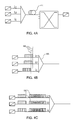
- FIG. 4A shows that the decorrelation is obtained at the optical level by introducing an optical fiber (410) of sufficient length (several kilometers) which, by the effect of the chromatic dispersion, will create a time difference between adjacent channels.
- the device of FIG. 4B makes it possible to obtain the same effect by the introduction of delays, between adjacent channels, at the electrical level (420) before mixing the wavelengths constituting the band of wavelengths (425).
- the decorrelation of the bit sequences is simply obtained by inverting the transmitted data (430) between adjacent channels in such a way that these take values opposite to the transmission but which will be restored on reception.
Landscapes
- Physics & Mathematics (AREA)
- Electromagnetism (AREA)
- Engineering & Computer Science (AREA)
- Computer Networks & Wireless Communication (AREA)
- Signal Processing (AREA)
- Optical Communication System (AREA)
Abstract
Description
- Une pluralité de dispositifs d'émission pour recevoir une pluralité de signaux électriques de données, et moduler respectivement une pluralité de signaux optiques ayant des longueurs d'onde différentes, puis les multiplexer spectralement en un signal optique composite.
- Une fibre optique de transmission.
- Un dispositif pour démultiplexer ledit signal optique composite en une pluralité de signaux optiques.
- Une pluralité de dispositifs de réception connectés respectivement à chacune des sorties du dispositif pour dé-multiplexer.
Claims (8)
- Système de transmission par fibres optiques, notamment un commutateur optique, comprenant :caractérisé en ce que ledit second dispositif pour régénérer comprend un second circuit d'horloge commun (320) pour fournir un signal d'horloge à chacun desdits régénérateurs; et un moyen (305) d'acquisition de signal d'horloge, commun à tous les régénérateurs du second dispositif pour régénérer, ce moyen d'acquisition étant connecté à l'une des sorties dudit moyen pour démultiplexer (330) et à une entrée dudit second circuit d'horloge commun (320).un premier dispositif pour régénérer une pluralité de signaux électriques ou optiques (211, 213, 215, 217) en un signal optique composite (235) incluant une pluralité de longueurs d'ondes,un premier circuit d'horloge (220) fournissant un signal d'horloge commun pour régénérer ces signaux électriques ou optiques ;un second dispositif pour régénérer ledit signal optique composite (235) en une pluralité de signaux électriques ou optiques (311, 313, 315, 317), ledit second dispositif comprenant un moyen pour dé-multiplexer (330) ladite pluralité de longueurs d'ondes et une pluralité de régénérateurs (310, 312, 314, 316) connectés respectivement à chacune des sorties dudit moyen pour dé-multiplexer, chacun des régénérateurs comprenant une entrée d'horloge (321) et une sortie de données (319) pour restituer un signal régénéré ;
- Système selon la revendication 1, caractérisé en ce qu'il comprend en outre des moyens pour une compensation chromatique de ladite pluralité de longueurs d'ondes
- Système selon la revendication 1, caractérisé en ce qu'il comporte des moyens (410, 420) pour décorréler des séquences de données servant à moduler lesdites longueurs d'ondes, avant de les commuter.
- Système selon la revendication 3, caractérisé en ce que les moyens pour décorréler comportent une fibre optique à dispersion chromatique non nulle (410) pour appliquer un délai temporel optique audit signal optique composite.
- Système selon la revendication 3, caractérisé en ce que les moyens pour décorréler comportent des moyens électriques pour retarder (420) au moins une des séquences de bits servant à moduler lesdites longueurs d'ondes.
- Système selon la revendication 3, caractérisé en ce les moyens pour décorréler comportent des moyens pour inverser la séquence de bits (430) servant à moduler lesdites longueurs d'ondes.
- Système selon l'une quelconque des revendications 3 à 6, caractérisé en ce que ladite dé-corrélation est toujours synchrone à une horloge du premier dispositif pour régénérer.
- Système selon l'une des revendications 4 à 6, caractérisé en ce que ledit décalage temporel, mesuré en périodes de bit, est supérieur à n+0,25 et inférieur à n+0,75, n étant un nombre entier.
Applications Claiming Priority (2)
| Application Number | Priority Date | Filing Date | Title |
|---|---|---|---|
| FR0115108 | 2001-11-22 | ||
| FR0115108A FR2832571B1 (fr) | 2001-11-22 | 2001-11-22 | Systeme de transmission par fibres optiques a horloge commune |
Publications (2)
| Publication Number | Publication Date |
|---|---|
| EP1315320A2 true EP1315320A2 (fr) | 2003-05-28 |
| EP1315320A3 EP1315320A3 (fr) | 2003-06-18 |
Family
ID=8869668
Family Applications (1)
| Application Number | Title | Priority Date | Filing Date |
|---|---|---|---|
| EP02292737A Withdrawn EP1315320A3 (fr) | 2001-11-22 | 2002-11-04 | Système de transmission par fibres optiques à horloge commune |
Country Status (4)
| Country | Link |
|---|---|
| US (1) | US20030095312A1 (fr) |
| EP (1) | EP1315320A3 (fr) |
| JP (1) | JP2003198463A (fr) |
| FR (1) | FR2832571B1 (fr) |
Cited By (3)
| Publication number | Priority date | Publication date | Assignee | Title |
|---|---|---|---|---|
| US4944462A (en) * | 1989-05-02 | 1990-07-31 | Cummins-Allison Corp. | Shredder |
| WO2004054151A1 (fr) * | 2002-12-02 | 2004-06-24 | Ekinops | Procede de transmission synchrone longue distance par fibre optique |
| WO2008072945A1 (fr) * | 2006-12-15 | 2008-06-19 | Instituto Tecnologico Y De Estudios Superiores De Monterrey | Régénérateur de phase de signaux optiques pour formats de modulation différentielle avec changements de phase |
Families Citing this family (5)
| Publication number | Priority date | Publication date | Assignee | Title |
|---|---|---|---|---|
| US7881617B2 (en) * | 2006-02-24 | 2011-02-01 | Cisco Technology, Inc. | Buffering schemes for optical packet processing |
| US7835649B2 (en) * | 2006-02-24 | 2010-11-16 | Cisco Technology, Inc. | Optical data synchronization scheme |
| JP2008035265A (ja) * | 2006-07-28 | 2008-02-14 | Oki Electric Ind Co Ltd | 多波長キャリア抑圧光パルス信号生成装置 |
| US7864747B2 (en) | 2008-03-28 | 2011-01-04 | Embarq Holdings Company, Llc | System and method for communicating timing to a remote node |
| BR112021004133A8 (pt) * | 2018-11-05 | 2023-05-09 | Lyteloop Tech Llc | Sistemas e métodos para construir, operar e controlar múltiplos amplificadores, regeneradores e transceptores usando os componentes comuns compartilhados |
Family Cites Families (6)
| Publication number | Priority date | Publication date | Assignee | Title |
|---|---|---|---|---|
| IT1159851B (it) * | 1978-06-20 | 1987-03-04 | Cselt Centro Studi Lab Telecom | Perfezionamenti ai sistemi di trasmissione a divisione di lunghezza d'onda |
| FR2759516B1 (fr) * | 1997-02-10 | 1999-03-26 | Alsthom Cge Alcatel | Procede et dispositif de regeneration en ligne d'un signal transmis par solitons multiplexes en longueur d'onde et systeme de telecommunications optiques comprenant un tel dispositif de regeneration |
| US6782210B1 (en) * | 1999-08-25 | 2004-08-24 | Nippon Telegraph And Telephone Corporation | Optical packet routing network system based on optical label switching technique |
| US6594049B1 (en) * | 1999-10-29 | 2003-07-15 | Lucent Technologies Inc. | Optical router |
| FR2805417B1 (fr) * | 2000-02-21 | 2002-05-31 | Cit Alcatel | Regenerateur pour systeme de transmission a multiplexage en longueur d'onde |
| WO2002035665A1 (fr) * | 2000-10-19 | 2002-05-02 | Fujitsu Limited | Emetteur optique, repeteur optique et recepteur optique, et procede de transmission optique |
-
2001
- 2001-11-22 FR FR0115108A patent/FR2832571B1/fr not_active Expired - Fee Related
-
2002
- 2002-11-04 EP EP02292737A patent/EP1315320A3/fr not_active Withdrawn
- 2002-11-13 US US10/292,453 patent/US20030095312A1/en not_active Abandoned
- 2002-11-21 JP JP2002337926A patent/JP2003198463A/ja not_active Withdrawn
Cited By (5)
| Publication number | Priority date | Publication date | Assignee | Title |
|---|---|---|---|---|
| US4944462A (en) * | 1989-05-02 | 1990-07-31 | Cummins-Allison Corp. | Shredder |
| WO2004054151A1 (fr) * | 2002-12-02 | 2004-06-24 | Ekinops | Procede de transmission synchrone longue distance par fibre optique |
| US8090268B2 (en) | 2002-12-02 | 2012-01-03 | Ekinops | Long-distance synchronous transmission method using optical fiber |
| WO2008072945A1 (fr) * | 2006-12-15 | 2008-06-19 | Instituto Tecnologico Y De Estudios Superiores De Monterrey | Régénérateur de phase de signaux optiques pour formats de modulation différentielle avec changements de phase |
| US8280261B2 (en) | 2006-12-15 | 2012-10-02 | Instituto Technologico Y De Estudios Superiores De Monterrey | Optical signal phase regenerator for formats of differential modulation with phase changes |
Also Published As
| Publication number | Publication date |
|---|---|
| EP1315320A3 (fr) | 2003-06-18 |
| US20030095312A1 (en) | 2003-05-22 |
| FR2832571B1 (fr) | 2004-04-16 |
| JP2003198463A (ja) | 2003-07-11 |
| FR2832571A1 (fr) | 2003-05-23 |
Similar Documents
| Publication | Publication Date | Title |
|---|---|---|
| EP2724483B1 (fr) | Systeme de transmission sur fibre optique multi-coeur | |
| JP2679953B2 (ja) | 高密度光波長分割多重化 | |
| FR2779295A1 (fr) | Dispositif de compensation de dispersion | |
| FR2715524A1 (fr) | Système de communication de type soliton optique ainsi qu'émetteur et récepteur optiques pour ce système. | |
| CA2414369A1 (fr) | Systeme et procede permettant d'augmenter la capacite d'un canal de reseau de communications a fibre optique | |
| EP0541409A1 (fr) | Système de transmission bidirectionnelle, notamment par fibre optique, avec une porteuse unique pour les deux sens de transmission | |
| EP0897624B1 (fr) | Procede et dispositif de regeneration en ligne d'un signal transmis par solitons multiplexes en longueur d'onde et systeme de telecommunications optiques comprenant un tel dispositif de regeneration | |
| EP1969748B1 (fr) | Transmission optique entre un terminal central et une pluralite de terminaux clients via un reseau optique | |
| CA2292276A1 (fr) | Procede de reduction des distortions d'intensite induites par la modulation de phase croisee dans un systeme de transmission a fibre optique a multiplexage de longueur d'onde et unite pour la mise en oeuvre du procede | |
| EP1315320A2 (fr) | Système de transmission par fibres optiques à horloge commune | |
| EP2569883A1 (fr) | Dispositif de terminaison de ligne optique permettant la mise en oeuvre d'une technique de modulation ofdm | |
| FR2829327A1 (fr) | Reseau en anneau realise a partir d'un bus optique double | |
| Rau et al. | Wavelength multicasting using an ultra high-speed all-optical wavelength converter | |
| EP1193995A1 (fr) | Commutateur pour réseau de transmission optique utilisant le multiplexage en longueur d'onde | |
| Vodhanel et al. | Performance of an 8-wavelength 8-node WDM ring network experiment with 80 Gb/s capacity | |
| Roy et al. | Symmetric Wavelength Reused Bidirectional RSOA Based WDM-PON with NRZ Data in Downstream and Upstream | |
| EP1986361B1 (fr) | Dispositif de commutation optique pour réseau optique transparent | |
| JP2005094287A (ja) | 光伝送方法及びシステム並びに光送信方法及び装置 | |
| EP2009827B1 (fr) | Dispositif de démultiplexage temporel optique | |
| EP0500452A1 (fr) | Réseau de communication optique | |
| Alam et al. | Performance evaluation of CDMA, WDMA, DWDMA networks | |
| EP2007049B1 (fr) | Dispositif de transmission de signaux optiques multidébits | |
| FR2852185A1 (fr) | Module de selection pour commutateur de signaux optiques et commutateur de signaux optiques | |
| WO2023187300A1 (fr) | Méthode et dispositif de codage iq dense pour système de communication sdm sur fibre optique | |
| Chowdhury et al. | Performance analysis of an optical cross connect at DWDM system |
Legal Events
| Date | Code | Title | Description |
|---|---|---|---|
| PUAI | Public reference made under article 153(3) epc to a published international application that has entered the european phase |
Free format text: ORIGINAL CODE: 0009012 |
|
| PUAL | Search report despatched |
Free format text: ORIGINAL CODE: 0009013 |
|
| AK | Designated contracting states |
Designated state(s): AT BE BG CH CY CZ DE DK EE ES FI FR GB GR IE IT LI LU MC NL PT SE SK TR |
|
| AX | Request for extension of the european patent |
Extension state: AL LT LV MK RO SI |
|
| AK | Designated contracting states |
Designated state(s): AT BE BG CH CY CZ DE DK EE ES FI FR GB GR IE IT LI LU MC NL PT SE SK TR |
|
| AX | Request for extension of the european patent |
Extension state: AL LT LV MK RO SI |
|
| 17P | Request for examination filed |
Effective date: 20031218 |
|
| AKX | Designation fees paid |
Designated state(s): AT BE BG CH CY CZ DE DK EE ES FI FR GB GR IE IT LI LU MC NL PT SE SK TR |
|
| 17Q | First examination report despatched |
Effective date: 20040421 |
|
| GRAP | Despatch of communication of intention to grant a patent |
Free format text: ORIGINAL CODE: EPIDOSNIGR1 |
|
| STAA | Information on the status of an ep patent application or granted ep patent |
Free format text: STATUS: THE APPLICATION IS DEEMED TO BE WITHDRAWN |
|
| 18D | Application deemed to be withdrawn |
Effective date: 20060217 |