EP1315235A1 - Adaptive array device, adaptive array method and program - Google Patents
Adaptive array device, adaptive array method and program Download PDFInfo
- Publication number
- EP1315235A1 EP1315235A1 EP01958500A EP01958500A EP1315235A1 EP 1315235 A1 EP1315235 A1 EP 1315235A1 EP 01958500 A EP01958500 A EP 01958500A EP 01958500 A EP01958500 A EP 01958500A EP 1315235 A1 EP1315235 A1 EP 1315235A1
- Authority
- EP
- European Patent Office
- Prior art keywords
- weight
- value
- reception
- calculating
- adjusted
- Prior art date
- Legal status (The legal status is an assumption and is not a legal conclusion. Google has not performed a legal analysis and makes no representation as to the accuracy of the status listed.)
- Granted
Links
Images


Classifications
-
- H—ELECTRICITY
- H04—ELECTRIC COMMUNICATION TECHNIQUE
- H04B—TRANSMISSION
- H04B7/00—Radio transmission systems, i.e. using radiation field
- H04B7/02—Diversity systems; Multi-antenna system, i.e. transmission or reception using multiple antennas
- H04B7/04—Diversity systems; Multi-antenna system, i.e. transmission or reception using multiple antennas using two or more spaced independent antennas
- H04B7/08—Diversity systems; Multi-antenna system, i.e. transmission or reception using multiple antennas using two or more spaced independent antennas at the receiving station
- H04B7/0837—Diversity systems; Multi-antenna system, i.e. transmission or reception using multiple antennas using two or more spaced independent antennas at the receiving station using pre-detection combining
- H04B7/0842—Weighted combining
- H04B7/0848—Joint weighting
- H04B7/0851—Joint weighting using training sequences or error signal
-
- H—ELECTRICITY
- H01—ELECTRIC ELEMENTS
- H01Q—ANTENNAS, i.e. RADIO AERIALS
- H01Q3/00—Arrangements for changing or varying the orientation or the shape of the directional pattern of the waves radiated from an antenna or antenna system
- H01Q3/26—Arrangements for changing or varying the orientation or the shape of the directional pattern of the waves radiated from an antenna or antenna system varying the relative phase or relative amplitude of energisation between two or more active radiating elements; varying the distribution of energy across a radiating aperture
- H01Q3/2605—Array of radiating elements provided with a feedback control over the element weights, e.g. adaptive arrays
Definitions
- the present invention relates to an adaptive array apparatus that performs SDMA using an adaptive array method.
- SDMA Space Division Multiple Access
- SDMA is a method used by a wireless base station to communicate with each of a plurality of mobile stations at the same timeslot and frequency, by dividing a communication space.
- the division of the communication space is realized when the wireless base station forms an optimum directivity pattern separately for each individual mobile station.
- a directivity pattern shows the direction in which signals are transmitted or received, and the intensity at which those signals are transmitted or received.
- the wireless base station is equipped with an adaptive array apparatus as a device for forming directivity patterns.
- the adaptive array apparatus is chiefly composed of a plurality of antennas and a DSP (Digital Signal Processor), and forms any directivity patterns freely by weighting with particular values the amplitude and phase of each signal transmitted or received by each antenna.
- the adaptive array apparatus then performs transmission and reception of signals using the formed patterns .
- a value used for weighting is referred to as a weight signal
- a set of weight signals for forming a directivity pattern is referred to as a weight vector.
- the adaptive array apparatus forms an optimal directivity pattern for a mobile station, by tracking the movements of the mobile station, which sends signals in a direction unforeknown to the adaptive array apparatus.
- One of the principles on which the adaptive array apparatus operates is MMSE (Minimum Mean Square Error).
- MMSE requires reference signals.
- a reference signal serves as a target when weighting received signals and combining them to produce a signal.
- An adaptive array apparatus that uses MMSE determines a weight vector so as to minimize a difference between the reference signal and the combined signal. Using such a weight vector creates a directivity pattern which is optimal for receiving signals from the mobile station.
- each timeslot includes predetermined bit patterns such as a preamble and a unique word at the top and a payload in the following section.
- the adaptive array apparatus can use the preamble, the unique word and the like as reference signals.
- the adaptive array apparatus sets a certain weight vector as an initial value, and compares a reference signal, such as a preamble and a unique word, with a signal that is obtained by weighting using the weight vector. In order to minimize the difference between them, the adaptive array apparatus adjusts the value of the weight vector. By repeating such processing for a bit pattern in symbol units, the weight vector converges on a certain value after a period of time. Following this, signals of the payload is weighted by the converged weight vector and then extracted. After receiving the predetermined bit pattern such as the preamble and the unique word, the adaptive array apparatus identifies the extracted signals and uses them as reference signals on the premise that the identification is correct.
- a reference signal such as a preamble and a unique word
- the conventional adaptive array apparatus described above has problems in that a weight vector converges slowly and unstably.
- converging unstable means that the value of a weight vector fluctuates and does not settle at a certain value.
- Converging slowly means that it takes long from the setting of an initial value of a weight vector to the convergence of the weight vector.
- Another reason is associated with the way of setting an initial value of a weight vector. Since the initial value is fixed in the conventional adaptive array apparatus, it takes long for the weight vector value to converge on an optimal value. In fact, in many cases weight vectors cannot converge sufficiently.
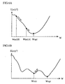
- FIGS. 6 A and 6B show difference curves.
- a weight vector is multidimensional and so the difference curve has a curved surface in a multidimensional space, though the weight vector is illustrated as a one-dimensional vector here for the sake of convenience.
- the weight vector is adjusted consecutively in a direction that decreases the value of the difference curve.
- Winit (A) it does not take long for an initial value Winit (A) to converge on an optimal value Wopt, as it is close to Wopt.
- Winit (B) it takes long for an initial value Winit (B) to converge, as it is not close to Wopt. If only a single fixed initial value is used, it takes long for the initial value to converge, as it is not close to an optimal value.
- Winit may be a local minimum value due to noise or other factors. In that case, it is impossible for the weight vector value to pass a peak and converge on an optimal value Wopt which is a general minimum value.
- the first object can be achieved by an adaptive array apparatus which has a weight converge on an optimal value, by repeatedly adjusting the weight using predetermined calculations so as to minimize a difference between a desired signal and a signal which is weighted using the weight and combined, the adaptive array apparatus including: a judging unit for judging whether an adjusted weight is located closer to the optimal value than a reference value; and a changing unit for changing a first step size in accordance with the judgment result of the judging unit, the first step size being used to determine the extent to which the weight should be adjusted in the predetermined calculations.
- the adaptive array apparatus may have a plurality of antennas, wherein the judging unit judges that the adjusted weight is located closer to the optimal value than the reference value when the number of times the weight is adjusted reaches twice the number of antennas, and the changing unit changes the first step size from a first value to a second value when the adjusted weight is judged to be located closer to the optimal value than the reference value, the second value corresponding to a lower rate at which the weight is adjusted than the first value.
- the judging unit may judge that the adjusted weight is located closer to the optimal value than the reference value when the difference between the combined signal and the desired signal becomes smaller than a predetermined value, wherein the changing unit changes the first step size from a first value to a second value when the adjusted weight is judged to be located closer to the optimal value than the reference value, the second value corresponding to a lower rate at which the weight is adjusted than the first value.
- the judging unit may judge that the adjusted weight is located closer to the optimal value than the reference value when a frequency offset converges at a lower rate than a predetermined value, the frequency offset being adjusted successively, wherein the changing unit changes the first step size from a first value to a second value when the adjusted weight is judged to be located closer to the optimal value than the reference value, the second value corresponding to a lower rate at which the weight is adjusted than the first value.
- the changing unit may also change a second step size from a third value to a fourth value, the second step size being used to determine the extent to which the frequency offset should be adjusted, the fourth value corresponding to a lower rate at which the frequency offset should be adjusted than the third value.
- the judging unit may judge that the adjusted weight is located closer to the optimal value than the reference value when a phase component of the difference becomes smaller than a phase component of the predetermined value.
- the second object can be achieved by the adaptive array apparatus that further includes: a reception response vector calculating unit for calculating a reception response vector of an immediately preceding reception timeslot in a TDMA/TDD (Time Division Multiple Access/Time Division Duplex) reception and transmission cycle; a weight vector calculating unit for calculating a weight vector of the immediately preceding reception timeslot from the reception response vector; and an initial value setting unit for setting the weight vector of the immediately preceding reception timeslot, as an initial value for calculating a weight vector of a present reception timeslot.
- TDMA/TDD Time Division Multiple Access/Time Division Duplex
- the weight vector calculated from a Wiener solution of the preceding reception timeslot is set as an initial value of use in successive calculation of weight vectors, enabling the weight vector to converge on an optimal value in a short period of time.
- the adaptive array apparatus may include: a reception response vector calculating unit for calculating a reception response vector of an immediately preceding reception timeslot in the TDMA / TDD reception and transmission cycle; a correlation matrix calculating unit for calculating a correlation matrix from the reception response vector; and an initial value setting unit for setting the correlation matrix as an initial value for calculating a weight vector of a present reception timeslot.
- the correlation matrix with a fewer error elements in the preceding reception frame is set as an initial value of use in successive calculation of weight vectors, enabling the weight vector to converge on an optimal value in a short period of time.
- the initial value setting unit may set an adjusted correlation matrix as an initial value instead of the correlation matrix, the adjusted correlation matrix being obtained by adding a predetermined value to diagonal elements of the correlation matrix.
- a predeterminedvalue is added to the diagonal elements of the correlation matrix, enhancing the convergency of a weight vector.
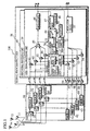
- FIG. 1 is a block diagram showing a main part of a wireless base station 100 corresponding to an adaptive array apparatus.
- the wireless base station 100 includes antennas 11 to 14, a radio unit 20 and a signal processing unit 38.
- the radio unit 20 includes switching units 21 to 24 for switching reception and transmission, and reception units 31 to 34 for converting high-frequency signals, which are sent from the antennas 11 to 14, into low-frequency signals and outputting them to the signal processing unit 38 .
- the radio unit 20 further includes transmission units 61 to 64 for converting low-frequency signals that are input from the signal processing unit 38 into high-frequency signals, and amplifying and outputting them to the antennas 11 to 14.
- the signal processing unit 38 is chiefly composed of a programmable digital signal processor, and performs signal processing on signals that travel between the wireless base station 100 and each mobile station, with which the wireless base station 100 performs multiplex communication using TDMA/TDD and SDMA.
- FIG. 2 shows a TDMA/TDD frame of 5ms taken along a time axis, which is a unit of a transmission and reception cycle.
- the TDMA/TDD frame consists of four transmission timeslots (TO to T3) and four reception timeslots (R0 to R3), which are each 625 ⁇ s long.
- the wireless base station 100 can compress 5ms of information to 625 ⁇ s of information and transmit them to a maximum of four mobile stations in each of the timeslots T0 to T3.
- the wireless base station 100 receives from each mobile station 5ms of information that has been compressed into 625 ⁇ s of information.
- the wireless base station 100 performs spatial multiplexing for two mobile stations in each timeslot using the adaptive array method.
- the use of TDMA/TDD and SDMA enables the wireless base station 100 to perform spatial multiplexing for a plurality of mobile stations.
- the wireless base station 100 communicates with first and second mobile stations in the transmission timeslot T0 and reception timeslot R0, and communicates with third and fourth mobile stations in the transmission timeslot T1 and reception timeslot R1.
- the signal processing unit 38 realizes such multiplex communication, and processes reception/ transmission signals for two mobile stations in each timeslot of a TDMA/TDD frame.
- FIG. 1 shows the construction of the signal processing unit 38 in terms of function.
- the signal processing unit 38 includes a user I signal processing unit 39, a user II signal processing unit 40 and adders 56 to 59.
- the user I signal processing unit 39 in a reception timeslot, weights four signals input from the reception units 31 to 34 with predetermined weight signals, and thereby extracts signals sent from a mobile station to the wireless base station 100.
- the user I signal processing unit 39 adds weights to signals that are to be transmitted from the wireless base station 100 to the mobile station with the same weight signals, and then distributes the weighted signals to the transmission units 61 to 64, which outputs the weighted signals. More detailed explanation of their operation will be given later.
- the user II signal processing unit 40 carries out the same processing as the user I signal processing unit 39 on a mobile station, which is different from a mobile station that the processing of the user I signal processing unit 39 is dealing with.
- the adders 56 to 59 in a transmission timeslot, each add signals that are output from the user I signal processing unit 39 and user II signal processing unit 40 respectively, and output the results to the corresponding transmission units 61 to 64.
- the user I signal processing unit 39 includes multipliers 41 to 44, an adder 45, a demodulation circuit 46, an adaptive processor 70, a modulation circuit 55 and multipliers 51 to 54.
- the multipliers 41 to 44 and the adder 45 in a reception timeslot, weight and combine each signal sent from the corresponding reception units 31 to 34 with particular weight signals calculated by a reception weight calculating unit 72.
- the demodulation circuit 46 demodulates the combined symbol waved signals sent from the adder 45 and outputs the resulting bit data sequence.
- the modulation circuit 55 modulates a bit data sequence to be transmitted in a transmission timeslot into a symbol waved signals.
- the multipliers 51 to 54 multiply the modulated signals provided by the modulation circuit 55 by weight signals, and output the results. These weight signals have the same values as those calculated in a preceding reception timeslot.
- the adaptive processor 70 is a primary construction element of the present invention, and provides a weight signal to each of the multipliers 41 to 44 in a reception timeslot while adjusting the weight signal so as to minimize a difference between a reference signal and the weight signal which is obtained through weighting and combining performed by the multipliers 41 to 44 and the adder 45.
- the adaptive processor 70 provides a weight signal, calculated in a reception timeslot that comes 2.5ms earlier, to the multipliers 51 to 54.
- the reference signal is used as a target when weighting and combining received signals.
- a sequence of given signals transmitted from a mobile station such as a preamble and unique word, serves as reference signals.
- a sequence of signals demodulated by the demodulation circuit 46 from combined signals serves as reference signals.
- the adaptive processor 70 includes a remodulation circuit 47, a memory 48, a switch 49, a counter 50, a parameter control unit 71, the reception weight calculating unit 72, a correlation matrix operator 303, an initial weight operator 304, a reception response vector calculator 305 and an initial value memory 309.
- the remodulation circuit 47 remodulates a bit data sequence sent from the demodulation circuit 46 into symbol waved signals, and outputs them to the switch 49. These signals are used as reference signals by the reception weight calculating unit 72 to calculate weight signals.
- the memory 48 stores given bit patterns such as a preamble and unique word, and outputs a symbol waved signals of the bit pattern through the switch 49. Under the PHS(Personal Handyphone System)standard, other given bit pattern includes a rampbit and a start symbol. The memory 48 stores a part or all of those given bit patterns and outputs their symbol waved signals. Such signals are also used as reference signals by the reception weight calculating unit 72.
- the counter 50 counts the number of symbols in a symbol waved signal that is sent from the remodulation circuit 47 or the memory 48 to the switch 49.
- the switch 49 uses the number of symbols to distinguish a reception period for a given bit pattern from a reception period for the remaining signals contained in a reception timeslot.
- the switch 49 selects an output from the memory 48 in the former period and an output from the remodulation circuit 47 in the latter period, and then outputs a selected output to the reception weight calculating unit 72.
- the parameter control unit 71 adjusts a parameter that is used to determine a rate of adjusting a weight signal, according to the extent at which the weight signal converges on an ideal weight signal after successive modification. More detailed explanation of such modifications will be given later.
- the reception weight calculating unit 72 calculates weight signals to provide to the multipliers 41 to 44 and multipliers 51 to 54. More specifically, in a reception period of a reception timeslot where a given bit pattern is received, initial weight signal values stored in the initial value memory 309 are provided to the multipliers 41 to 44, respectively. Then, combined signals, which is obtained by weighting and combining by the multipliers 41 to 44 and the adder 45, are input to the reception weight calculating unit 72. The reception weight calculating unit 72 calculates a difference between each of the combined signals and a respective reference signal which has been provided by the memory 48 through the switch 49. The reception weight calculating unit 72 adjusts the initial weight signal so as to minimize the difference, calculates a new weight signal and sends it to the multiplier again.
- the reception weight calculating unit 72 calculates a difference between the combined signal and the reference signal which is input from the remodulation circuit 47 through the switch 49, and makes precise adjustment for the weight signal on the basis of the difference.
- the reception response vector calculator 305 calculates an ensemble average of a product of reception signals and user signals contained in the entire reception frame.
- Reception response vectors are calculated using the following expressions, where a reception response vector calculated from a signal S1, which is sent from a first mobile station (hereafter referred to as a user I ), is RV1 and a reception response vector calculated from a signal S2, which is sent from a second mobile station (hereafter referred to as a user II), is RV2;
- RV1 [RV 11 , RV 12 , RV 13 , RV 14 ]
- T RV2 [RV 21 , RV 22 , RV 23 , RV 24 ]
- T RV 11 E [X 1 (t) S1* (t)]
- RV 12 E [X 2 (t) S1* (t)]
- RV 13 E [X 3 (t) S1* (t)]
- RV 14 E [X 4 (t) S1* (t)]
- RV 21 E [X 1 (t) S2*
- RV1 is calculated by the user I signal processing unit 39 and RV2 is calculated by the user II signal processing unit 40.
- the resulting values provided by any one of the units are sent to the other and shared between the two units.
- the initial value memory 309 stores an initial value P(0) of a correlation matrix calculated by the correlation matrix operator 303 and an initial value W(0) of a weight vector calculated by the initial weight operator 304.
- a reference signal memory 310 stores a reference signal d(t).
- the correlation matrix operator 303 calculates an initial value P (0) of a correlation matrix by applying reception response vectors RV1 and RV2 of a preceding frame to the following expressions, and stores the results in the initial value memory 309.
- the reception weight calculating unit 72 calculates a reception weight vector using LMS and RLS, and adjusts the reception weight vector in each reception timeslot by successively calculating new weight vectors. More specifically, the reception weight calculating unit 72 calculates weights Wrx1 to Wrx4 using sequences of symbols X 1 to X 4 , which are sent from the radio unit 20, a sequence of symbols d (t) , which are reference signals stored in the memory 48 or signals generated by the radio unit itself, and initial values W(0) and P(0), which are stored in the initial value memory 309. The reception weight calculating unit 72 then outputs the resulting weights Wrx1 to Wrx4.
- FIG. 3 is a flowchart showing the operational procedure for calculating an initial value by the signal processing unit 38.
- RV 1i E [X i (t) S1*(t)]
- RV 2i E [X i (t) S2* (t)] (step S401).
- FIG. 4 is a flowchart showing the detailed procedure for calculating a weight signal, centering on the reception weight calculating unit 72.
- the reception weight calculating unit 72 and other units perform the processing described in FIG. 4 in each timeslot.
- the reception weight calculating unit 72 has the parameter control unit 71 execute processing of adjusting parameters (step S205). More detailed explanation of this processing will be given later.
- the reception weight calculating unit 72 adjusts the weight vector using expressions that are based on RLS (Recursive Least Squares) algorithm (steps S 209 to S219). After the preamble section, the reception weight calculating unit 72 adjusts the weight vector using expressions that are based on LMS algorithm (steps S 225 to S 229). Note that the preamble section here refers to a period for receiving the given bit pattern such as a unique word.
- step S207 the reception weight calculating unit 72 compensates for frequency offset while t is within the preamble section (step S209) .
- X(t) e -j ⁇ t is determined and regarded as being X(t).
- H refers to conjugate transpose.
- P(0) is read from the initial value memory 309 and used as a reference signal.
- e d (t) - W H (t - 1) X (t) (step S215).
- the reception weight calculating unit 72 ends the series of processing if t has reached the end of the reception timeslot, and if not, repeats the processing from step S205 (step S203) .
- the reception weight calculating unit 72 When t passes the preamble section and goes beyond, since any reference signals are stored in the memory 48 for the following section, the reception weight calculating unit 72 begins to generate reference signals on its own. Which is to say, the reception weight calculating unit 72 either calculates a reference signal, d (t) Det t [W (t-1) H X (t)] (step S225) or employs a signal sent from the remodulation circuit 47 as a reference signal d(t).
- reception weight calculating unit 72 performs step S221, repeats the processing from step S205 and ends the processing when t reaches the end of a reception timeslot (step S223).
- Such frequency offset processing may be saved after step S219, and performed only after step S229.
- step S205 the parameter control unit 71 adjusts a parameter that determines to which extent a weight vector should be adjusted, depending on whether the adjusted weight vector is located closer to an optimal weight vector than a reference value as a result of the processing from steps S207 through 223.
- the parameter control unit 71 carriers out one of the adjusting methods 1 to 5. Any combination of these methods may also be used.
- the parameter control unit 71 then changes an initial value of at least one of the forgetting coefficient ⁇ , step size ⁇ and frequency offset step size ⁇ , so that the weight vector is adjusted at a lower rate. This means that an initial value of the forgetting coefficient ⁇ is raised, while initial values of the step size ⁇ and frequency offset step size ⁇ are decreased.
- a weight vector in theory converges to some extent by the time the number of times it is adjusted reaches twice the number of antennas. Accordingly, when the number of times the weight vector is adjusted reaches twice the number of antennas, by adjusting one of the parameters so that the weight vector is adjusted at a lower rate, both the convergence speed and stability can be enhanced. Which is to say, the time required for the convergence can be reduced with an increase in the convergence speed, by adjusting the weight vector at a higher rate when the number of times the weight vector is adjusted is smaller than twice the number of antennas. Also, the convergence stability can be improved by lowering the rate at which the weight vector is adjusted when the number of times the weight vector is adjusted is greater than twice the number of antennas.
- the parameter control unit 71 judges that an adjusted weight is located closer to an optimal value than a reference value when a phase error of an error e(t) becomes smaller than a predetermined value stored in the memory. At that time, the parameter control unit 71 changes an initial value of at least one of the forgetting coefficient ⁇ , step size ⁇ and frequency offset step size ⁇ , so that the weight vector is adjusted at a lower rate.
- the phase error refers to a difference between a phase component of a reference signal d(t) and a phase component of a combined signal W H (t - 1) X (t) , and that the error e(t) is calculated in step S215 or step 5227.
- the phase error becomes greater than a predetermined value
- the time required for convergence can be reduced with an increase in the convergence speed
- the phase error becomes smaller than the predetermined value the convergence stability can be enhanced with a fall in the rate at which the weight vector is adjusted.
- the parameter control unit 71 judges that an adjusted weight is located closer to an optimal value than a reference value when an error e(t) becomes smaller than a predetermined value stored in the memory. At that time, the parameter control unit 71 changes an initial value of at least one of the forgetting coefficient ⁇ , step size ⁇ and frequency offset step size ⁇ , so that the weight vector is adjusted at a lower rate.
- the error e(t) is calculated in step S215 or step S227. This being so, when the error e(t) is greater than a predetermined value, the time required for convergence can be reduced with an increase in the convergence speed, and when the error e(t) is smaller than the predetermined value, the convergence stability can be improved with a fall in the rate at which the weight vector is adjusted.
- the parameter control unit 71 judges that an adjusted weight is not located closer to an optimal value than a reference value when a phase error of an error e(t) becomes greater than a predetermined value stored in the memory. At that time, the parameter control unit 71 changes an initial value of at least one of the forgetting coefficient ⁇ , step size ⁇ and frequency offset step size ⁇ , so that the weight vector is adjusted at a higher rate.
- the phase error refers to a difference between a phase component of a reference signal d(t) and a phase component of a combined signal W H (t-1) X (t) , and that the error e(t) is calculated in step S215 or step S227.
- the parameter control unit 71 judges that an adjusted value is not located closer to an optimal value than a reference value when an error e(t) becomes greater than a predetermined value stored in the memory. At that time, the parameter control unit 71 changes an initial value of at least one of the forgetting coefficient ⁇ , step size ⁇ and frequency offset step size ⁇ , so that the weight vector is adjusted at a higher rate.
- the error e(t) is calculated in step S215 or step S227.
- the wireless base station 100 in this embodiment uses a weight vector and a correlation matrix, which are obtained from a reception response vector of the preceding reception frame, as an initial value to adjust the weight vector, so that the adjusted weight vector converges on an optimal value in a shorter period of time.
- the parameter control unit 71 adjusts parameters in accordance with how closer is an adjusted weight located, as described earlier, so that the weight vector converges on an optimal value in a shorter period of time without experiencing diffusion.
- initial values of both a correlation matrix and a weight vector are calculated, but either of them may be used single.
- only an initial value of the weight vector may be calculated as described above while using an identity unit multiplied by a particular constant as an initial value of the correlation matrix, which is a conventional method.
- only an initial value of the correlation matrix may be calculated as described above while using 0 vector as an initial value of the weight vector, which is a conventional method. This is applicable not only to an adaptive array apparatus that operates under the MMSE standard but also to other algorithms for successive weight estimation.
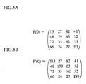
- FIG. 5A shows one example of an initial value P(0) of a correlation matrix calculated by the correlation matrix operator 303.
- FIG. 5B shows an initial value P' (0) of the adjusted correlation matrix. As shown in FIG. 5B, a predetermined value 100 is added to the diagonal elements P 11 , P 22 , P 33 and P 44 of P' (0).
- RLS algorithm is used to calculate a weight vector in the preamble section and LMS algorithm is used in the section following the preamble section in the above embodiment, the invention should not be limited to such.
- either RLS or LMS algorithm may be used single throughout a timeslot to calculate a weight vector.
- Using RLS algorithm throughout a timeslot to calculate a weight vector can be achieved by having reference signals generated, as in the case of the LMS algorithm, instead of reading pre-stored reference signals from the reference signal memory.
- an ensemble average of a product of reception signals and user signals in the entire reception frame is used as a reception response vector in the above embodiment, the invention should not be limited to such.
- An ensemble average in a particular section, for example in the preamble section, may be used as a reception response vector.
- the method for calculating a response vector should not be limited to such.
- the adaptive array apparatus of the present invention is suitable for a communication unit of a base station in a communication system.
Landscapes
- Engineering & Computer Science (AREA)
- Computer Networks & Wireless Communication (AREA)
- Signal Processing (AREA)
- Radio Transmission System (AREA)
- Variable-Direction Aerials And Aerial Arrays (AREA)
- Debugging And Monitoring (AREA)
- Measurement Of Velocity Or Position Using Acoustic Or Ultrasonic Waves (AREA)
- Communication Control (AREA)
- Error Detection And Correction (AREA)
- Soundproofing, Sound Blocking, And Sound Damping (AREA)
- Mobile Radio Communication Systems (AREA)
Abstract
Description
Claims (16)
- An adaptive array apparatus that has a weight converge on an optimal value, by repeatedly adjusting the weight using predetermined calculations so as tominimize a difference between a desired signal and a signal which is weighted using the weight and combined, the adaptive array apparatus comprising:judging means for judging whether an adjusted weight is located closer to the optimal value than a reference value; andchanging means for changing a first step size in accordance with the judgment result of the judging means, the first step size being used to determine the extent to which the weight should be adjusted in the predetermined calculations.
- The adaptive array apparatus of Claim 1 having a plurality of antennas,
wherein the judging means judges that the adjusted weight is located closer to the optimal value than the reference value when the number of times the weight is adjusted reaches twice the number of antennas, and
the changing means changes the first step size from a first value to a second value when the adjusted weight is judged to be located closer to the optimal value than the reference value, the second value corresponding to a lower rate at which the weight is adjusted than the first value. - The adaptive array apparatus of Claim 1,
wherein the judging means judges that the adjusted weight is located closer to the optimal value than the reference value when the difference between the combined signal and the desired signal becomes smaller than a predetermined value, and
the changing means changes the first step size from a first value to a second value when the adjusted weight is judged to be located closer to the optimal value than the reference value, the second value corresponding to a lower rate at which the weight is adjusted than the first value. - The adaptive array apparatus of Claim 1,
wherein the judging means judges that the adjusted weight is located closer to the optimal value than the reference value when a frequency offset converges at a lower rate than a predetermined value, the frequency offset being adjusted successively, and
the changing means changes the first step size from a first value to a second value when the adjusted weight is judged to be located closer to the optimal value than the reference value, the second value corresponding to a lower rate at which the weight is adjusted than the first value. - The adaptive array apparatus of Claim 2 or Claim 3,
wherein the changing means also changes a second step size from a third value to a fourth value, the second step size being used to determine the extent to which the frequency offset should be adjusted, the fourth value corresponding to a lower rate at which the frequency offset should be adjusted than the third value. - The adaptive array apparatus of Claim 3,
wherein the judging means judges that the adjusted weight is located closer to the optimal value than the reference value when a phase component of the difference becomes smaller than a phase component of the predetermined value. - The adaptive array apparatus of Claim 1, further comprising:reception response vector calculating means for calculating a reception response vector of an immediately preceding reception timeslot in a TDMA/TDD (Time Division Multiple Access/Time Division Duplex) reception and transmission cycle;weight vector calculating means for calculating a weight vector of the immediately preceding reception timeslot from the reception response vector; andinitial value setting means for setting the weight vector of the immediately preceding reception timeslot, as an initial value for calculating a weight vector of a present reception timeslot.
- The adaptive array apparatus of Claim 1, further comprising:reception response vector calculating means for calculating a reception response vector of an immediately preceding reception timeslot in the TDMA/TDD reception and transmission cycle;correlation matrix calculating means for calculating a correlation matrix from the reception response vector; andinitial value setting means for setting the correlation matrix as an initial value for calculating a weight vector of a present reception timeslot.
- The adaptive array apparatus of Claim 8, further comprising:wherein the initial value setting means also sets the weight vector of the immediately preceding reception timeslot as an initial value for calculating the weight vector of the present reception timeslot.weight vector calculating means for calculating a weight vector of the immediately preceding reception timeslot, based on the reception response vector,
- The adaptive array apparatus of Claim 8 or Claim 9,
wherein the initial value setting means sets an adjusted correlation matrix as an initial value instead of the correlation matrix, the adjusted correlation matrix being obtained by adding a predetermined value to diagonal elements of the correlation matrix. - An adaptive array method used in an adaptive array apparatus that has a weight converge on an optimal value, by repeatedly adjusting the weight using predetermined calculations so as to minimize a difference between a desired signal and a signal which is weighted using the weight and combined, the adaptive array apparatus comprising:judging step for judging whether an adjusted weight is located closer to the optimal value than a reference value; andchanging step for changing a first step size in accordance with the judgment result of the judging step, the first step size being used to determine the extent to which the weight should be adjusted in the predetermined calculations.
- The adaptive array method of Claim 11, further comprising:reception response vector calculating step for calculating a reception response vector of an immediately preceding reception timeslot in a TDMA/TDD (Time Division Multiple Access/Time Division Duplex) reception and transmission cycle;weight vector calculating step for calculating a weight vector of the immediately preceding reception timeslot from the reception response vector; andinitial value setting step for setting the weight vector of the immediately preceding reception timeslot, as an initial value for calculating a weight vector of a present reception timeslot.
- The adaptive array method of Claim 11, further comprising:reception response vector calculating step for calculating a reception response vector of an immediately preceding reception timeslot in the TDMA/TDD reception and transmission cycle;correlation matrix calculating step for calculating a correlation matrix from the reception response vector; andinitial value setting step for setting the correlation matrix as an initial value for calculating a weight vector of a present reception timeslot.
- A program to be executed by a computer in an adaptive array apparatus that has a weight converge on an optimal value, by repeatedly adjusting the weight using predetermined calculations so as to minimize a difference between a desired signal and a signal which is weighted using the weight and combined, the adaptive array apparatus comprising:judging step for judging whether an adjusted weight is located closer to the optimal value than a reference value; andchanging step for changing a first step size in accordance with the judgment result of the judging step, the first step size being used to determine the extent to which the weight should be adjusted in the predetermined calculations
- The program of Claim 14, further comprising:reception response vector calculating step for calculating a reception response vector of an immediately preceding reception timeslot in a TDMA/TDD (Time Division Multiple Access/Time Division Duplex) reception and transmission cycle;weight vector calculating step for calculating a weight vector of the immediately preceding reception timeslot from the reception response vector; andinitial value setting step for setting the weight vector of the immediately preceding reception timeslot, as an initial value for calculating a weight vector of a present reception timeslot.
- The program of Claim 14, further comprising:reception response vector calculating step for calculating a reception response vector of an immediately preceding reception timeslot in the TDMA/TDD reception and transmission cycle;correlation matrix calculating step for calculating a correlation matrix from the reception response vector; andinitial value setting step for setting the correlation matrix as an initial value for calculating a weight vector of a present reception timeslot.
Applications Claiming Priority (5)
| Application Number | Priority Date | Filing Date | Title |
|---|---|---|---|
| JP2000256526 | 2000-08-25 | ||
| JP2000256526A JP2002077007A (en) | 2000-08-25 | 2000-08-25 | Wireless base station, array receiving apparatus, and array receiving method |
| JP2000256527 | 2000-08-25 | ||
| JP2000256527A JP3363879B2 (en) | 2000-08-25 | 2000-08-25 | Adaptive array device, weight updating method, and program recording medium |
| PCT/JP2001/007299 WO2002017432A1 (en) | 2000-08-25 | 2001-08-27 | Adaptive array device, adaptive array method and program |
Publications (3)
| Publication Number | Publication Date |
|---|---|
| EP1315235A1 true EP1315235A1 (en) | 2003-05-28 |
| EP1315235A4 EP1315235A4 (en) | 2003-09-10 |
| EP1315235B1 EP1315235B1 (en) | 2008-05-28 |
Family
ID=26598535
Family Applications (1)
| Application Number | Title | Priority Date | Filing Date |
|---|---|---|---|
| EP01958500A Expired - Lifetime EP1315235B1 (en) | 2000-08-25 | 2001-08-27 | Adaptive array device, adaptive array method and program |
Country Status (8)
| Country | Link |
|---|---|
| US (1) | US7298774B2 (en) |
| EP (1) | EP1315235B1 (en) |
| CN (1) | CN1330051C (en) |
| AT (1) | ATE397300T1 (en) |
| AU (1) | AU2001280170A1 (en) |
| DE (1) | DE60134238D1 (en) |
| TW (1) | TW504865B (en) |
| WO (1) | WO2002017432A1 (en) |
Cited By (4)
| Publication number | Priority date | Publication date | Assignee | Title |
|---|---|---|---|---|
| WO2005041353A1 (en) * | 2003-10-23 | 2005-05-06 | Telecom Italia S.P.A | Antenna system and method for configuring a radiating pattern |
| EP1482656A3 (en) * | 2003-05-29 | 2005-10-19 | Fujitsu Limited | Adaptive controller and adaptive control method that can adaptively control a plurality of variable high frequency devices at high speed |
| WO2008034458A1 (en) * | 2006-09-22 | 2008-03-27 | Telecom Italia S.P.A. | Method and system for syntesizing array antennas |
| CN100444663C (en) * | 2003-10-20 | 2008-12-17 | 三洋电机株式会社 | Base station device with multiple antennas |
Families Citing this family (11)
| Publication number | Priority date | Publication date | Assignee | Title |
|---|---|---|---|---|
| JP3475163B2 (en) * | 2000-09-08 | 2003-12-08 | 三洋電機株式会社 | Wireless device |
| JP3895228B2 (en) * | 2002-05-07 | 2007-03-22 | 松下電器産業株式会社 | Wireless communication apparatus and direction of arrival estimation method |
| JP4364274B2 (en) * | 2005-02-18 | 2009-11-11 | 富士通株式会社 | Interference reduction receiver |
| JP2007124411A (en) * | 2005-10-28 | 2007-05-17 | Kyocera Corp | Adaptive array antenna apparatus and adaptive control method thereof |
| CN100466774C (en) * | 2007-05-18 | 2009-03-04 | 华为技术有限公司 | A sectorized base station |
| US10490892B2 (en) * | 2007-12-06 | 2019-11-26 | Spatial Digital Systems, Inc. | Satellite ground terminal incorporating a smart antenna that rejects interference |
| US8903685B2 (en) | 2010-10-27 | 2014-12-02 | King Fahd University Of Petroleum And Minerals | Variable step-size least mean square method for estimation in adaptive networks |
| US8547854B2 (en) | 2010-10-27 | 2013-10-01 | King Fahd University Of Petroleum And Minerals | Variable step-size least mean square method for estimation in adaptive networks |
| US8462892B2 (en) | 2010-11-29 | 2013-06-11 | King Fahd University Of Petroleum And Minerals | Noise-constrained diffusion least mean square method for estimation in adaptive networks |
| US20120314630A1 (en) * | 2011-06-13 | 2012-12-13 | Gordon Kent Walker | Broadcast band segmentation structures to enable better utilization of available spectrum |
| US9837991B2 (en) | 2013-04-10 | 2017-12-05 | King Fahd University Of Petroleum And Minerals | Adaptive filter for system identification |
Family Cites Families (13)
| Publication number | Priority date | Publication date | Assignee | Title |
|---|---|---|---|---|
| JPH01194613A (en) | 1988-01-29 | 1989-08-04 | Hitachi Ltd | Automating equalizer initializing system |
| JPH06508805A (en) * | 1991-08-05 | 1994-10-06 | ザ、ブロクター、エンド、ギャンブル、カンパニー | plug-in handle |
| US5956624A (en) * | 1994-07-12 | 1999-09-21 | Usa Digital Radio Partners Lp | Method and system for simultaneously broadcasting and receiving digital and analog signals |
| JP3359460B2 (en) * | 1995-03-20 | 2002-12-24 | 沖電気工業株式会社 | Adaptive filter and echo canceller |
| JP3391662B2 (en) * | 1997-06-06 | 2003-03-31 | 松下電器産業株式会社 | Adaptive array antenna receiver |
| JP3216704B2 (en) * | 1997-08-01 | 2001-10-09 | 日本電気株式会社 | Adaptive array device |
| JP3229848B2 (en) * | 1997-10-22 | 2001-11-19 | 三洋電機株式会社 | Weight vector calculation method for digital wireless communication system |
| US6240133B1 (en) * | 1998-02-05 | 2001-05-29 | Texas Instruments Incorporated | High stability fast tracking adaptive equalizer for use with time varying communication channels |
| JP3465739B2 (en) | 1998-04-07 | 2003-11-10 | 日本電気株式会社 | CDMA adaptive antenna receiving apparatus and communication system |
| JP2000188568A (en) * | 1998-10-13 | 2000-07-04 | Matsushita Electric Ind Co Ltd | Receiver |
| WO2000079702A1 (en) * | 1999-06-23 | 2000-12-28 | Japan As Represented By President Of Hokkaido University | Radio device |
| KR20010101457A (en) * | 1999-11-10 | 2001-11-14 | 다니구찌 이찌로오, 기타오카 다카시 | Adaptive array communication system and receiver |
| TW513873B (en) * | 2000-07-27 | 2002-12-11 | Sanyo Electric Co | Radio equipment capable of real time change of antenna directivity and Doppler frequency estimating circuit used for the radio equipment |
-
2001
- 2001-08-27 US US10/362,647 patent/US7298774B2/en not_active Expired - Lifetime
- 2001-08-27 WO PCT/JP2001/007299 patent/WO2002017432A1/en not_active Ceased
- 2001-08-27 AT AT01958500T patent/ATE397300T1/en not_active IP Right Cessation
- 2001-08-27 CN CNB018173977A patent/CN1330051C/en not_active Expired - Fee Related
- 2001-08-27 DE DE60134238T patent/DE60134238D1/en not_active Expired - Fee Related
- 2001-08-27 EP EP01958500A patent/EP1315235B1/en not_active Expired - Lifetime
- 2001-08-27 AU AU2001280170A patent/AU2001280170A1/en not_active Abandoned
- 2001-08-27 TW TW090120996A patent/TW504865B/en not_active IP Right Cessation
Cited By (7)
| Publication number | Priority date | Publication date | Assignee | Title |
|---|---|---|---|---|
| EP1482656A3 (en) * | 2003-05-29 | 2005-10-19 | Fujitsu Limited | Adaptive controller and adaptive control method that can adaptively control a plurality of variable high frequency devices at high speed |
| CN100444663C (en) * | 2003-10-20 | 2008-12-17 | 三洋电机株式会社 | Base station device with multiple antennas |
| WO2005041353A1 (en) * | 2003-10-23 | 2005-05-06 | Telecom Italia S.P.A | Antenna system and method for configuring a radiating pattern |
| US7835768B2 (en) | 2003-10-23 | 2010-11-16 | Telecom Itala S.p.A. | Antenna system and method for configuring a radiating pattern |
| CN1860645B (en) * | 2003-10-23 | 2013-04-03 | 意大利电信股份公司 | Antenna system and method of configuring a radiation pattern |
| WO2008034458A1 (en) * | 2006-09-22 | 2008-03-27 | Telecom Italia S.P.A. | Method and system for syntesizing array antennas |
| US8629808B2 (en) | 2006-09-22 | 2014-01-14 | Telecom Italia S.P.A. | Method and system for synthesizing array antennas |
Also Published As
| Publication number | Publication date |
|---|---|
| CN1489805A (en) | 2004-04-14 |
| TW504865B (en) | 2002-10-01 |
| WO2002017432A1 (en) | 2002-02-28 |
| EP1315235B1 (en) | 2008-05-28 |
| US20040048581A1 (en) | 2004-03-11 |
| US7298774B2 (en) | 2007-11-20 |
| ATE397300T1 (en) | 2008-06-15 |
| CN1330051C (en) | 2007-08-01 |
| AU2001280170A1 (en) | 2002-03-04 |
| EP1315235A4 (en) | 2003-09-10 |
| DE60134238D1 (en) | 2008-07-10 |
Similar Documents
| Publication | Publication Date | Title |
|---|---|---|
| JP4131702B2 (en) | Reduce interference using a simple antenna array | |
| JP3779063B2 (en) | Wireless communication apparatus and wireless communication method | |
| EP1315235B1 (en) | Adaptive array device, adaptive array method and program | |
| US6931244B2 (en) | Radio equipment capable of real time change of antenna directivity and doppler frequency estimating circuit used for the radio equipment | |
| US7071874B2 (en) | Radio terminal device, transmission directivity control method, and transmission directivity control program | |
| EP0874475A2 (en) | Adaptive antenna array using a combined coherent and constant modulus reference signal | |
| JP2003501971A (en) | Apparatus and method for beamforming in a changing interference environment | |
| WO2004062136A1 (en) | Method and system for adaptively combining signals | |
| WO2002007258A2 (en) | Adaptive antenna for use in same frequency networks | |
| EP1622411A2 (en) | Improvement of throughput for a radio system using SDMA | |
| US7209713B2 (en) | Transmission method and radio apparatus for substantially constant receiving power level at a remote terminal | |
| US7269202B2 (en) | Radio apparatus, swap detecting method and swap detecting program | |
| JP2000188568A (en) | Receiver | |
| CN100592655C (en) | Wireless device and Doppler frequency estimation circuit for the wireless device | |
| EP1336261B1 (en) | Determinant-based synchronization techniques and systems | |
| JP4253173B2 (en) | Wireless device, transmission control switching method, and transmission control switching program | |
| CN101208829A (en) | Adaptive array wireless communication apparatus and method thereof | |
| JP2002050989A (en) | Doppler frequency estimation circuit and wireless device using Doppler frequency estimation circuit | |
| US7398098B2 (en) | Radio base apparatus, transmission power control method, and transmission power control program | |
| EP1763269A1 (en) | Channel allocation method and base station device using the same | |
| JP3579363B2 (en) | Wireless receiving apparatus and wireless receiving method | |
| JP4510681B2 (en) | Radio base apparatus, communication method selection method, and communication method selection program | |
| JP3416865B2 (en) | Adaptive antenna device | |
| KR100925432B1 (en) | Weight Update Method of Communication System Using Smart Antenna | |
| JP2003060568A (en) | Radio base station, transmission power control method, and transmission power control program |
Legal Events
| Date | Code | Title | Description |
|---|---|---|---|
| PUAI | Public reference made under article 153(3) epc to a published international application that has entered the european phase |
Free format text: ORIGINAL CODE: 0009012 |
|
| 17P | Request for examination filed |
Effective date: 20030324 |
|
| AK | Designated contracting states |
Designated state(s): AT BE CH CY DE DK ES FI FR GB GR IE IT LI LU MC NL PT SE TR |
|
| AX | Request for extension of the european patent |
Extension state: AL LT LV MK RO SI |
|
| A4 | Supplementary search report drawn up and despatched |
Effective date: 20030729 |
|
| 17Q | First examination report despatched |
Effective date: 20040614 |
|
| GRAP | Despatch of communication of intention to grant a patent |
Free format text: ORIGINAL CODE: EPIDOSNIGR1 |
|
| GRAS | Grant fee paid |
Free format text: ORIGINAL CODE: EPIDOSNIGR3 |
|
| GRAA | (expected) grant |
Free format text: ORIGINAL CODE: 0009210 |
|
| AK | Designated contracting states |
Kind code of ref document: B1 Designated state(s): AT BE CH CY DE DK ES FI FR GB GR IE IT LI LU MC NL PT SE TR |
|
| REG | Reference to a national code |
Ref country code: GB Ref legal event code: FG4D |
|
| REG | Reference to a national code |
Ref country code: CH Ref legal event code: EP |
|
| REF | Corresponds to: |
Ref document number: 60134238 Country of ref document: DE Date of ref document: 20080710 Kind code of ref document: P |
|
| REG | Reference to a national code |
Ref country code: IE Ref legal event code: FG4D |
|
| PG25 | Lapsed in a contracting state [announced via postgrant information from national office to epo] |
Ref country code: ES Free format text: LAPSE BECAUSE OF FAILURE TO SUBMIT A TRANSLATION OF THE DESCRIPTION OR TO PAY THE FEE WITHIN THE PRESCRIBED TIME-LIMIT Effective date: 20080908 |
|
| PG25 | Lapsed in a contracting state [announced via postgrant information from national office to epo] |
Ref country code: NL Free format text: LAPSE BECAUSE OF FAILURE TO SUBMIT A TRANSLATION OF THE DESCRIPTION OR TO PAY THE FEE WITHIN THE PRESCRIBED TIME-LIMIT Effective date: 20080528 Ref country code: AT Free format text: LAPSE BECAUSE OF FAILURE TO SUBMIT A TRANSLATION OF THE DESCRIPTION OR TO PAY THE FEE WITHIN THE PRESCRIBED TIME-LIMIT Effective date: 20080528 |
|
| NLV1 | Nl: lapsed or annulled due to failure to fulfill the requirements of art. 29p and 29m of the patents act | ||
| PG25 | Lapsed in a contracting state [announced via postgrant information from national office to epo] |
Ref country code: SE Free format text: LAPSE BECAUSE OF FAILURE TO SUBMIT A TRANSLATION OF THE DESCRIPTION OR TO PAY THE FEE WITHIN THE PRESCRIBED TIME-LIMIT Effective date: 20080828 Ref country code: PT Free format text: LAPSE BECAUSE OF FAILURE TO SUBMIT A TRANSLATION OF THE DESCRIPTION OR TO PAY THE FEE WITHIN THE PRESCRIBED TIME-LIMIT Effective date: 20081028 Ref country code: DK Free format text: LAPSE BECAUSE OF FAILURE TO SUBMIT A TRANSLATION OF THE DESCRIPTION OR TO PAY THE FEE WITHIN THE PRESCRIBED TIME-LIMIT Effective date: 20080528 |
|
| PG25 | Lapsed in a contracting state [announced via postgrant information from national office to epo] |
Ref country code: BE Free format text: LAPSE BECAUSE OF FAILURE TO SUBMIT A TRANSLATION OF THE DESCRIPTION OR TO PAY THE FEE WITHIN THE PRESCRIBED TIME-LIMIT Effective date: 20080528 |
|
| PG25 | Lapsed in a contracting state [announced via postgrant information from national office to epo] |
Ref country code: MC Free format text: LAPSE BECAUSE OF NON-PAYMENT OF DUE FEES Effective date: 20080831 |
|
| REG | Reference to a national code |
Ref country code: CH Ref legal event code: PL |
|
| PLBE | No opposition filed within time limit |
Free format text: ORIGINAL CODE: 0009261 |
|
| STAA | Information on the status of an ep patent application or granted ep patent |
Free format text: STATUS: NO OPPOSITION FILED WITHIN TIME LIMIT |
|
| 26N | No opposition filed |
Effective date: 20090303 |
|
| PG25 | Lapsed in a contracting state [announced via postgrant information from national office to epo] |
Ref country code: CH Free format text: LAPSE BECAUSE OF NON-PAYMENT OF DUE FEES Effective date: 20080831 Ref country code: LI Free format text: LAPSE BECAUSE OF NON-PAYMENT OF DUE FEES Effective date: 20080831 |
|
| PG25 | Lapsed in a contracting state [announced via postgrant information from national office to epo] |
Ref country code: IE Free format text: LAPSE BECAUSE OF NON-PAYMENT OF DUE FEES Effective date: 20080827 |
|
| REG | Reference to a national code |
Ref country code: GB Ref legal event code: 732E Free format text: REGISTERED BETWEEN 20090723 AND 20090729 |
|
| PG25 | Lapsed in a contracting state [announced via postgrant information from national office to epo] |
Ref country code: IT Free format text: LAPSE BECAUSE OF FAILURE TO SUBMIT A TRANSLATION OF THE DESCRIPTION OR TO PAY THE FEE WITHIN THE PRESCRIBED TIME-LIMIT Effective date: 20080528 Ref country code: DE Free format text: LAPSE BECAUSE OF NON-PAYMENT OF DUE FEES Effective date: 20090303 |
|
| PG25 | Lapsed in a contracting state [announced via postgrant information from national office to epo] |
Ref country code: LU Free format text: LAPSE BECAUSE OF NON-PAYMENT OF DUE FEES Effective date: 20080827 Ref country code: CY Free format text: LAPSE BECAUSE OF FAILURE TO SUBMIT A TRANSLATION OF THE DESCRIPTION OR TO PAY THE FEE WITHIN THE PRESCRIBED TIME-LIMIT Effective date: 20080528 |
|
| PG25 | Lapsed in a contracting state [announced via postgrant information from national office to epo] |
Ref country code: TR Free format text: LAPSE BECAUSE OF FAILURE TO SUBMIT A TRANSLATION OF THE DESCRIPTION OR TO PAY THE FEE WITHIN THE PRESCRIBED TIME-LIMIT Effective date: 20080528 |
|
| PG25 | Lapsed in a contracting state [announced via postgrant information from national office to epo] |
Ref country code: GR Free format text: LAPSE BECAUSE OF FAILURE TO SUBMIT A TRANSLATION OF THE DESCRIPTION OR TO PAY THE FEE WITHIN THE PRESCRIBED TIME-LIMIT Effective date: 20080829 |
|
| REG | Reference to a national code |
Ref country code: FR Ref legal event code: ST Effective date: 20110916 |
|
| PG25 | Lapsed in a contracting state [announced via postgrant information from national office to epo] |
Ref country code: FR Free format text: LAPSE BECAUSE OF NON-PAYMENT OF DUE FEES Effective date: 20080901 |
|
| PGFP | Annual fee paid to national office [announced via postgrant information from national office to epo] |
Ref country code: GB Payment date: 20110824 Year of fee payment: 11 Ref country code: FI Payment date: 20110810 Year of fee payment: 11 |
|
| GBPC | Gb: european patent ceased through non-payment of renewal fee |
Effective date: 20120827 |
|
| PG25 | Lapsed in a contracting state [announced via postgrant information from national office to epo] |
Ref country code: FI Free format text: LAPSE BECAUSE OF NON-PAYMENT OF DUE FEES Effective date: 20120827 |
|
| PG25 | Lapsed in a contracting state [announced via postgrant information from national office to epo] |
Ref country code: GB Free format text: LAPSE BECAUSE OF NON-PAYMENT OF DUE FEES Effective date: 20120827 |