EP1315168A1 - Cover gasket for hard disk device - Google Patents
Cover gasket for hard disk device Download PDFInfo
- Publication number
- EP1315168A1 EP1315168A1 EP01958561A EP01958561A EP1315168A1 EP 1315168 A1 EP1315168 A1 EP 1315168A1 EP 01958561 A EP01958561 A EP 01958561A EP 01958561 A EP01958561 A EP 01958561A EP 1315168 A1 EP1315168 A1 EP 1315168A1
- Authority
- EP
- European Patent Office
- Prior art keywords
- rubber
- adhesive agent
- bonding
- cover
- bonding surface
- Prior art date
- Legal status (The legal status is an assumption and is not a legal conclusion. Google has not performed a legal analysis and makes no representation as to the accuracy of the status listed.)
- Granted
Links
Images








Classifications
-
- G—PHYSICS
- G11—INFORMATION STORAGE
- G11B—INFORMATION STORAGE BASED ON RELATIVE MOVEMENT BETWEEN RECORD CARRIER AND TRANSDUCER
- G11B33/00—Constructional parts, details or accessories not provided for in the other groups of this subclass
- G11B33/12—Disposition of constructional parts in the apparatus, e.g. of power supply, of modules
- G11B33/121—Disposition of constructional parts in the apparatus, e.g. of power supply, of modules the apparatus comprising a single recording/reproducing device
-
- G—PHYSICS
- G11—INFORMATION STORAGE
- G11B—INFORMATION STORAGE BASED ON RELATIVE MOVEMENT BETWEEN RECORD CARRIER AND TRANSDUCER
- G11B33/00—Constructional parts, details or accessories not provided for in the other groups of this subclass
- G11B33/14—Reducing influence of physical parameters, e.g. temperature change, moisture, dust
-
- G—PHYSICS
- G11—INFORMATION STORAGE
- G11B—INFORMATION STORAGE BASED ON RELATIVE MOVEMENT BETWEEN RECORD CARRIER AND TRANSDUCER
- G11B33/00—Constructional parts, details or accessories not provided for in the other groups of this subclass
- G11B33/14—Reducing influence of physical parameters, e.g. temperature change, moisture, dust
- G11B33/1446—Reducing contamination, e.g. by dust, debris
- G11B33/1466—Reducing contamination, e.g. by dust, debris sealing gaskets
Definitions
- the present invention relates to a cover gasket used in a hard disc apparatus.
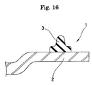
- a cover gasket 1 for a hard disc apparatus structured, as shown in Fig. 16, such that a rubber 3 corresponding to a sealing gasket is combined with a top cover 2 of the hard disc, and as means for combining the cover 2 and the rubber 3, there can be listed up a structure in which the rubber 3 is integrally molded with the cover 2, a structure in which the rubber 3 having a stainless core metal inserted therein is used and is laid on the cover 2, a structure in which a foamed urethane or a liquid rubber is applied to the cover 2 and cured, a structure in which the cover 2 and the rubber 3 are bonded by using an adhesive agent at a later stage, or the like.
- a mechanism by which running out of adhesive agent and peeling off of the rubber 3 are generated is as follows.
- the adhesive agent is applied onto a bonding surface 3a of the rubber 3 and the cover 2 and the rubber 3 are set to a bonding jig 11, thereafter heating and bonding are executed while applying a load P from above (the side of an upper jig 12) as shown in Fig. 18.
- a magnitude of the load P is too great, the rubber 3 is strongly pressed against a lower jig 13 and an excessive force P1 is generated in the outward direction. Accordingly, the adhesive agent 4 applied to the bonding surface 3a of the rubber 3 is forced out, whereby the running out of adhesive agent is caused.
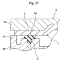
- the magnitude of load P that is, the pressing force of the bonding portion is controlled so that running out of the adhesive agent 4 as mentioned above is not generated and the bonding film does not become thin, and a carrier 14 (refer to Fig. 17) is provided in the jig 11 so as not to press the rubber 3 too much.
- the cover 2 is formed by a press molding, and particularly, in the case of press forming the cover 2 by using a stainless sheet or the like, since a spring back is generated after pressing, it is hard to make the flatness good enough to obtain a good bonding.
- the adhesive agent 4 when applying the adhesive agent 4 to the bonding surfaces, thereafter sticking the bonding surfaces and putting them on a hot plate in a pressing state, the adhesive agent 4 kept between the bonding surfaces due to a balance of the pressing force and a surface tension of the adhesive agent 4 looses the surface tension in accordance with an increase of temperature, the balance is lost at a certain temperature, and the adhesive agent 4 is pressed out from the bonding surface.
- the adhesive agent 4 is pressed out from a portion having a weak balance first, and a viscosity of the adhesive agent 4 is reduced due to the temperature increase, the adhesive agent is pressed out in such a manner as to run out irregularly from a plurality of portions instead of being pressed out uniformly from a whole of the outer periphery of the bonding surface. Accordingly, as a result, a state after running out becomes to be in a shape in which the adhesive agent 4 runs out zigzagedly from both sides of the rubber 3 like as legs of a scolopendra as shown in a model view in Fig. 20.
- the present invention is made by taking the above points into consideration, and an object of the present invention is to provide a cover gasket for a hard disc apparatus in which a cover and a rubber are later bonded by using an adhesive agent, wherein it is possible to prevent running out of an adhesive agent and peeling off of rubber as much as possible.
- a cover gasket for a hard disc apparatus in which a cover and a rubber are later bonded by using an adhesive agent, characterized in that a recess portion for storing the adhesive agent is provided on a bonding surface of the cover or the rubber.
- a cover gasket as recited in the first aspect mentioned above, characterized in that the recess portion is provided in the center in the width direction of the bonding surface of the rubber.
- a cover gasket as recited in the first aspect mentioned above, characterized in that the recess portion is provided in the end portions in the width direction of the bonding surface of the rubber.
- the adhesive agent is stored in the recess portion even in the case a pressing force at a time of bonding is large, so that it is possible to restrict running out of the adhesive agent to the minimum. Further, since a bonding film thickness becomes thicker by a part of adhesive agent being stored in the recess portion, it is possible to reinforce a bonding force.
- the recess portion is provided on the bonding surface of the rubber, it may be provided in the center in the width direction of the bonding surface as described in the second aspect, or it may be provided in the end portion in the width direction as described in the third aspect. In the latter case, the recess portions also open to side surfaces of the rubber.
- the later bonding means bonding the cover and the rubber after forming each of them in a product shape independently.
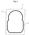
- Fig. 1 shows a state in which a cover gasket 1 in accordance with a first embodiment of the present invention is set to a bonding jig 11 for later bonding a cover 2 and a rubber (also called as a gasket in the narrow sense) 3 corresponding to constituting parts of the cover gasket 1 by using an adhesive agent 4.
- a bonding jig 11 for later bonding a cover 2 and a rubber (also called as a gasket in the narrow sense) 3 corresponding to constituting parts of the cover gasket 1 by using an adhesive agent 4.
- a recess portion 5 for storing an adhesive agent is previously provided in the center in the width direction of a bonding surface 3a of the rubber 3 so as to be formed in a groove shape, and the structure is made such that the cover 2 and the rubber 3 are bonded in a state in which a part of the adhesive agent 4 applied to the bonding surface 3a of the rubber 3 is stored in the recess portion 5, as shown in Fig. 1.
- the cover 2 is formed by press forming a raw material made of a stainless steel, an aluminum alloy or a laminated member (obtained by holding a resin material having a thickness 20 to 50 ⁇ m between the stainless steel, the aluminum alloy or the like) or the like.
- the rubber 3 is structured such that one surface of a comparatively wide flange portion 3b is formed as the bonding surface 3a with respect to the cover 2, and a comparatively narrow lip portion 3c is integrally formed in the center in the width direction in the opposite side thereto, and the rubber 3 is formed of a fluorine-contained rubber (FKM), an ethylene propylene diene rubber (EPDM), an acrylonitrile butadiene rubber (NBR), an acrylic rubber or the like, inwhichahardnessissettoaboutHs20to80. Further, the width in the cross sectional shape is actually about 1.5 to 2 mm, and the height in the same is actually formed to be about 1.5 mm.
- FKM fluorine-contained rubber
- EPDM ethylene propylene diene rubber
- NBR acrylonitrile butadiene rubber
- acrylic rubber or the like inwhichahardnessissettoaboutHs20to80.
- the groove-like recess portion 5 is provided all through the length of the rubber 3 along a layout of flat surface of the rubber 3, and the depth in the cross sectional shape is actually formed to be about 0.2 mm or less. Further, the width of the recess portion 5 shown in Fig. 1 is formed so as to be lager than the width of the lip portion 3c, however, may be set to be nearly equal to or less than the width of the lip portion 3c under a certain conditions of a rubber hardness, a compression allowance, a surface pressure or the like of the lip portion 3c.
- An epoxy resin based adhesive agent is frequently employed for the adhesive agent 4, and the adhesive agent 4 is applied to the rubber 3 in accordance with a transcription by a stamp, a printing or the like.
- an bonding jig 11 as illustrated is constructed of a combination of an upper jig 12 and a lower jig 13, and a carrier 14 for limiting a compression amount of the rubber 3 by holding the cover 2 between the carrier and the upper jig 12 at a time of bonding, a supporting portion 15 for supporting the rubber 3 at a time of bonding, a negative pressure suction port 16 and the like are provided an upper surface of the lower jig 13.
- the recess portion 5 for storing the adhesive agent is provided in the center in the width direction of the bonding surface 3a of the rubber 3 so as to be formed in the groove shape as mentioned above, a part of the adhesive agent 4 is stored in the groove-like recess portion 5 at a time of applying the adhesive agent 4 to the bonding surface 3a of the rubber 3, and the bonding is executed in this state. Accordingly, even when the pressing force at a time of bonding is great, the adhesive agent 4 is stored in the groove-like recess portion 5, so that as shown in a model view in Fig. 3, it is possible to restrict running out of the adhesive agent 4 to the minimum.
- only one groove-like recess portion 5 is provided on the bonding surface 3a of the rubber 3. In this case, however, as shown in Figs. 4 and 5, a plurality of (two in the drawing) groove-like recess portions may be provided.
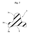
- the cross sectional shape of the groove-like recess portion 5 is formed in a long sideways rectangular (oblong) shape, however, as shown in Figs. 6 and 7, it may be formed in a non-rectangular shape (a circular arc shape in cross section in the drawing). In this case, it is possible to adjust an application direction or a generation direction of a pressing force or a shear stress at a time of bonding.
- the recess portion 5 is not limited to the groove-shaped structure, and a lot of recess portions 5 may be provided so as to be arranged along the longitudinal direction of the rubber 3, or it is possible to utilize a surface roughness formed on the bonding surface 3a.
- the recess portion 5 may be formed on the bonding surface of the cover 2, or may be formed on the bonding surfaces of both of the cover 2 and the rubber 3.
- the cross sectional shape of the recess portion 5 deforms so as to make the depth of the center portion in the width direction smaller due to the pressing, at a time of setting the depth of the recess portion 5 to be large, and there is a possibility that a part of the adhesive agent 4 within the recess portion 5 runs out from the end potion in the width direction of the recess portion 5, however, in the case that a plurality of groove-like recess portions 5 are provided on the bonding surface 3a of the rubber 3 as in the second embodiment, since a column portion (portion without recess portion being formed) 6 between a plurality of recess portions 5 serves as a support, it is possible to prevent the depth of the center portion in the width direction of the recess portion 5 from becoming small, whereby it is possible to prevent the adhesive agent 4 from running out even when setting the depth of the recess portion 5 to be large.
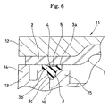
- Fig. 8 shows a state in which a cover gasket 1 in accordance with a sixth embodiment of the present invention is set to a bonding jig 11 for later bonding a cover 2 and a rubber (also called as a gasket in the narrow meaning sense) 3 corresponding to constituting parts of the cover gasket 1 by using an adhesive agent 4.
- a bonding jig 11 for later bonding a cover 2 and a rubber (also called as a gasket in the narrow meaning sense) 3 corresponding to constituting parts of the cover gasket 1 by using an adhesive agent 4.
- recess portions 5 for storing an adhesive agent are previously symmetrically provided respectively in both the end portions in the width direction of a bonding surface 3a of the rubber 3 so as to be formed in a beveled shape, and the structure is made such that the cover 2 and the rubber 3 are bonded in a state in which a part of the adhesive agent 4 applied to the bonding surface 3a of the rubber 3 is stored in the recess portions 5, as shown in Fig. 8.
- the cover 2 is formed by press forming a raw material made of a material obtained by applying an electroless nickel plating to a stainless steel, an aluminum alloy or a brass or the like, or a laminated member based on them or the like.
- the rubber 3 is structured such that one surface of a comparatively wide flange portion 3b is formed as the bonding surface 3a with respect to the cover 2, and a comparatively narrow lip portion 3c is integrally formed in the center in the width direction in the opposite side thereto, and the rubber 3 is formed of a fluorine-contained rubber (FKM), an ethylene propylene diene rubber (EPDM), an acrylonitrile butadiene rubber (NBR), an urethane rubber or the like, in which a hardness is set to about Hs 20 to 80. Further, the width in the cross sectional shape is actually about 1.5 to 2 mm, and the height in the same is actually formed to be about 1.5 mm.
- FKM fluorine-contained rubber
- EPDM ethylene propylene diene rubber
- NBR acrylonitrile butadiene rubber
- urethane rubber or the like in which a hardness is set to about Hs 20 to 80.
- the width in the cross sectional shape is actually about 1.5 to 2
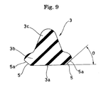
- the bevel-like recess portions 5 are provided all through the length of the rubber 3 along a layout of flat surface of the rubber 3, and the height in the cross sectional shape is actually formed to be about 0.2 mm or less. Further, the bevel-like recess portions 5 are formed in a shape obtained by obliquely cutting the end portions in the width direction of the bonding surface 3a, and have inclined surfaces 5a having a linear cross sectional shape, and it is preferable to set an angle of incline of the inclined surfaces 5a with respect to the bonding surface 3a between 20 and 70 degrees, and it is further preferable to set it to 40 degrees.
- the angle of incline ⁇ is set to the value mentioned above because it is possible to restrict discharge resistance and to sufficiently secure the capacity for storing the adhesive agent 4.
- the cross sectional shape corresponds to a shape in which the inclined surfaces 5a cross the bonding surface 3a out of square, and outlets in the running out direction of the adhesive agent 4 are gradually expanded.
- thermosetting type epoxy based adhesive agent is frequently employed for the adhesive agent 4, and the adhesive agent 4 is applied to the rubber 3 in accordance with a transcription by a stamp, a printing or the like.
- a bonding jig 11 as illustrated is constructed of a combination of an upper jig 12 and a lower jig 13, and a carrier 14 for limiting a compression amount of the rubber 3 by holding the cover 2 between the carrier and the upper jig 12 at a time of bonding, a supporting portion 15 for supporting the rubber 3 at a time of bonding, a negative pressure suction port 16 and the like are provided on the upper surface of the lower jig 13.
- the recess portions 5 for storing the adhesive agent are symmetrically provided in the both end portions in the width direction of the bonding surface 3a of the rubber 3 so as to be formed in the bevel shape as mentioned above, a part of the adhesive agent 4 is stored in the bevel-like recess portions 5 at a time of applying the adhesive agent 4 to the bonding surface 3a of the rubber 3, and the bonding is executed in this state. Accordingly, even when the pressing force at a time of bonding is great, the adhesive agent 4 is stored in the bevel-like recess portions 5, so that as shown in a model view in Fig. 3, it is possible to restrict running out of the adhesive agent 4 to the minimum. Further, since the adhesive agent 4 is stored in the bevel-like recess portions 5, an application area of the adhesive agent 4 is increased, whereby it is possible to reinforce the bonding force, thereby making it possible to prevent the peeling off from being generated in the rubber 3.
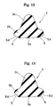
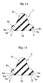
- the recess portions 5 are provided in the end portions in the width direction of the bonding surface 3a in the rubber 3 so as to be formed in the bevel shape, however, the recess portions may be formed in a notch shape as exemplified below.
- the inner surfaces of the recess portions 5 are formed by a combination of inclined surfaces 5a having a linear cross sectional shape and being provided with a predetermined angle of incline with respect to the bonding surface 3a, and horizontal surfaces 5b having a linear cross sectional shape and being parallel to the bonding surface 3a.
- This cross sectional shape corresponds to a shape in which the inclined surfaces 5a cross the bonding surface 3a out of square and outlets in the running out direction of the adhesive agent 4 are gradually expanded within the recess portions 5, in the same manner as that of the sixth embodiment mentioned above.
- the inner surfaces of the recess portions 5 are formed by curved surfaces 5c having a convex curved cross sectional shape.
- This cross sectional shape corresponds to a shape in which the curved surfaces 5c cross the bonding surface 3a out of square and outlets in the running out direction of the adhesive agent 4 are gradually expanded within the recess portions 5.
- the inner surfaces of the recess portions 5 are formed by curved surfaces 5d having a concave curved cross sectional shape.
- This cross sectional shape corresponds to a shape in which the curved surfaces 5d cross the bonding surface 3a out of square and outlets in the running out direction of the adhesive agent 4 are gradually expanded within the recess portions 5, in the same manner as that of the eighth embodiment mentioned above.
- the inner surfaces of the recess portions 5 are formed by curved surfaces 5d having a concave curved cross sectional shape. In this cross sectional shape, the curved surfaces 5d cross the bonding surface 3a on the square.
- the inner surfaces of the recess portions 5 are formed by a combination of vertical surfaces 5e having a linear cross sectional shape and being perpendicular to the bonding surface 3a, and horizontal surfaces 5b having the linear cross sectional shape and being parallel to the bonding surface 3a. In this cross sectional shape, the vertical surfaces 5e cross the bonding surface 3a on the square.
- the inner surfaces of the recess portions S are formed by a combination of vertical surfaces 5e having a linear cross sectional shape and being perpendicular to the bonding surface 3a, inclined surfaces 5a having the linear cross sectional shape and being provided with the predetermined angle of incline with respect to the bonding surface 3a, and horizontal surfaces 5b having the linear cross sectional shape and being parallel to the bonding surface 3a.
- the vertical surfaces 5e cross the bonding surface 3a on the square.
- All of the recess portions 5 constituted by the cross sectional shapes achieve the function of storing the adhesive agent 4 in the inner portions thereof, in particular, in the case of the shape in which the inclined surfaces 5a or the curved surfaces 5d cross the bonding surface 3a out of square and the outlets in the running out direction of the adhesive agent 4 are gradually expanded within the recess portions 5, as in the sixth, seventh, eighth or ninth embodiment mentioned above, discharge resistance of the adhesive agent 4 in the outlets is small, whereby the adhesive agent 4 applied to the bonding surface 3a of the rubber 3 slowly flows out to the recess portions 5 from the portion between the rubber 3 and the cover 2 before the temperature increases, so that it is possible to particularly effectively restrict the running out phenomenon of the adhesive agent 4.
- the adhesive agent 4 is a fluid having a high viscosity and flows out along angled walls of the rubber 3, it is also possible to particularly effectively restrict the running out phenomenon of the adhesive agent 4 . It is considered that this function and effect can be expected in the case that a cross angle ( ⁇ mentioned above) is within a range from 20 to 70 degrees.
- the present invention achieves the following effects.
- the recess portion for storing the adhesive agent is provided on the bonding surface of the cover or the rubber in the gasket formed by later bonding the cover and the rubber with using the adhesive agent, a part of the adhesive agent is stored within the recess portion at a time of applying the adhesive agent to the bonding surface, and the bonding operation is executed in this state. Accordingly, since the adhesive agent is stored in the recess portion even when the pressing force at the bonding time is large, it is possible to restrict running out of the adhesive agent to the minimum. Further, since the bonding film thickness is increased by a part of the adhesive agent being stored in the recess portion, it is possible to reinforce the bonding force, whereby it is possible to restrict peeling off in the rubber.
Landscapes
- Gasket Seals (AREA)
- Adhesives Or Adhesive Processes (AREA)
Abstract
Description
Claims (3)
- A cover gasket (1) for a hard disc apparatus in which a cover (2) and a rubber (3) are later bonded by using an adhesive agent (4), characterized in that a recess portion (5) for storing the cover (2) or the rubber (3).
- A cover gasket (1) as claimed in claim 1, characterized in that the recess portion (5) is provided in the center in the width direction of the bonding surface (3a) of the rubber (3).
- A cover gasket (1) as claimed in claim 1, characterized in that the recess portions (5) are provided in the end portions in the width direction of the bonding surface (3a) of the rubber (3).
Applications Claiming Priority (5)
| Application Number | Priority Date | Filing Date | Title |
|---|---|---|---|
| JP2000264831 | 2000-09-01 | ||
| JP2000264831 | 2000-09-01 | ||
| JP2000344617 | 2000-11-13 | ||
| JP2000344617 | 2000-11-13 | ||
| PCT/JP2001/007368 WO2002021534A1 (en) | 2000-09-01 | 2001-08-28 | Cover gasket for hard disk device |
Publications (3)
| Publication Number | Publication Date |
|---|---|
| EP1315168A1 true EP1315168A1 (en) | 2003-05-28 |
| EP1315168A4 EP1315168A4 (en) | 2006-04-26 |
| EP1315168B1 EP1315168B1 (en) | 2011-07-27 |
Family
ID=26599043
Family Applications (1)
| Application Number | Title | Priority Date | Filing Date |
|---|---|---|---|
| EP01958561A Expired - Lifetime EP1315168B1 (en) | 2000-09-01 | 2001-08-28 | Cover gasket for hard disk device |
Country Status (6)
| Country | Link |
|---|---|
| US (1) | US6769699B2 (en) |
| EP (1) | EP1315168B1 (en) |
| JP (1) | JP3778286B2 (en) |
| CN (1) | CN1232983C (en) |
| AU (1) | AU2001280206A1 (en) |
| WO (1) | WO2002021534A1 (en) |
Families Citing this family (25)
| Publication number | Priority date | Publication date | Assignee | Title |
|---|---|---|---|---|
| JP2004076877A (en) * | 2002-08-20 | 2004-03-11 | Nok Corp | Gasket |
| FR2856951B1 (en) * | 2003-07-01 | 2006-06-23 | Saint Gobain | GLAZING COMPRISING A REINFORCING ELEMENT |
| AU2003280644A1 (en) * | 2003-10-30 | 2005-05-19 | Nok Corporation | Thermoplastic elastomer composition, gasket, molded gasket, and structure for sealing between two members |
| US20050189720A1 (en) * | 2004-02-27 | 2005-09-01 | R & D Dynamics Corporation | Dynamic seal for use in high-speed turbomachinery |
| JP4148173B2 (en) * | 2004-03-31 | 2008-09-10 | Nok株式会社 | Gasket for fuel cell |
| TWI233966B (en) * | 2004-12-03 | 2005-06-11 | Benq Corp | Structure with resilient member and assembly method thereof |
| DE102004062880A1 (en) * | 2004-12-27 | 2006-07-06 | Siemens Ag | Display instrument and method for producing and disassembling a display instrument |
| US20060187577A1 (en) * | 2005-01-31 | 2006-08-24 | Metalform Asia Pte Ltd. | Disk drive cover |
| EP1978253B1 (en) * | 2006-01-25 | 2014-09-10 | Kabushiki Kaisha Toyota Jidoshokki | Electric compressor |
| US7852601B1 (en) | 2006-10-18 | 2010-12-14 | Western Digital Technologies, Inc. | Radial top cover gasket for disk drives |
| US20080191474A1 (en) * | 2007-02-12 | 2008-08-14 | Kotz George J | Tri-Lobed O-Ring Seal |
| JP2008269696A (en) * | 2007-04-19 | 2008-11-06 | Hitachi Global Storage Technologies Netherlands Bv | Magnetic disk drive and feedthrough soldering method |
| JP5179120B2 (en) * | 2007-08-24 | 2013-04-10 | 株式会社ブリヂストン | Multistage gasket |
| US8031431B1 (en) | 2009-03-02 | 2011-10-04 | Western Digital Technologies, Inc. | Disk drive having a top cover with anchor tabs |
| US8973921B2 (en) * | 2010-03-09 | 2015-03-10 | Baker Hughes Incorporated | High temperature/high pressure seal |
| US8695835B2 (en) * | 2011-02-03 | 2014-04-15 | Weener Plastik Gmbh | Closure cap for a fluid container and method for the fabrication |
| KR20130006962A (en) * | 2011-06-28 | 2013-01-18 | 시게이트 테크놀로지 인터내셔날 | Hard disk drive |
| JP2013223312A (en) * | 2012-04-16 | 2013-10-28 | Nippon Densan Corp | Base unit, spindle motor, and disk driving device |
| US10072776B2 (en) | 2015-08-20 | 2018-09-11 | Deere & Company | Fluid connector with annular groove and seal |
| US9734874B1 (en) | 2016-02-02 | 2017-08-15 | Western Digital Technologies, Inc. | Adhesive leak channel structure for hermetic sealing of a hard disk drive |
| CN107508950B (en) * | 2017-08-16 | 2020-08-25 | Oppo广东移动通信有限公司 | Housing assembly, sealing method thereof and electronic device |
| US11104101B2 (en) * | 2019-05-01 | 2021-08-31 | Autoliv Asp, Inc. | Systems and methods for sealing an airbag inflator base |
| JP7353577B2 (en) * | 2021-08-27 | 2023-10-02 | 日本発條株式会社 | Cover and recording device |
| JP2024073713A (en) * | 2022-11-18 | 2024-05-30 | ニデック株式会社 | Base plate and disk drive |
| US20250299703A1 (en) * | 2024-03-19 | 2025-09-25 | Western Digital Technologies, Inc. | Hard disk drive embedded gasket base |
Family Cites Families (16)
| Publication number | Priority date | Publication date | Assignee | Title |
|---|---|---|---|---|
| US3544066A (en) * | 1967-01-03 | 1970-12-01 | Pratt Co Henry | Valve seat structure |
| US3694894A (en) * | 1970-01-14 | 1972-10-03 | Parker Hannifin Corp | Method of inserting a seal in a face-cut groove |
| US4363192A (en) * | 1981-03-30 | 1982-12-14 | Soucy Armand L | Window mounting system |
| GB2143569B (en) * | 1983-07-26 | 1986-09-10 | Draftex Ind Ltd | Windscreen mounting |
| US4527807A (en) * | 1984-06-25 | 1985-07-09 | Dallas Corporation | Panel edge gasket |
| FR2616465B1 (en) * | 1987-06-12 | 1989-10-27 | Couvraneuf | VERTICAL FRONT JOINT FOR SEALING BETWEEN TWO WALLS |
| JP2517797B2 (en) * | 1990-12-27 | 1996-07-24 | 信越化学工業株式会社 | Packing assembly for hard disk device |
| JP2856577B2 (en) | 1991-09-26 | 1999-02-10 | 株式会社東芝 | Superconducting element |
| JPH05290563A (en) | 1992-04-10 | 1993-11-05 | Fujitsu Ltd | Closed structure |
| US5422766A (en) | 1994-01-03 | 1995-06-06 | Maxtor Corporation | Gasket for sealing a disk drive assembly |
| DE4404348A1 (en) * | 1994-02-11 | 1995-08-17 | Fritz Richard Gmbh & Co Kg | Process for the production and installation of a glass pane with a frame, in particular on a vehicle part |
| US5647255A (en) * | 1995-09-27 | 1997-07-15 | Quantum Corporation | Expandable gasket for a head disk assembly of a disk drive |
| JPH1144362A (en) | 1997-07-28 | 1999-02-16 | Nok Corp | Gasket |
| US6030104A (en) * | 1997-10-21 | 2000-02-29 | Shu; Cheng Cheng | Soft shelled lamp shade |
| US6202983B1 (en) * | 1999-10-13 | 2001-03-20 | Thomas A. Hartman | Valve seal structured to prevent circumferential slippage |
| US6494466B1 (en) * | 2000-04-20 | 2002-12-17 | Thomas A. Hartman | Valve seal construction with non-congruent side serrations |
-
2001
- 2001-08-28 EP EP01958561A patent/EP1315168B1/en not_active Expired - Lifetime
- 2001-08-28 AU AU2001280206A patent/AU2001280206A1/en not_active Abandoned
- 2001-08-28 US US10/148,892 patent/US6769699B2/en not_active Expired - Lifetime
- 2001-08-28 WO PCT/JP2001/007368 patent/WO2002021534A1/en not_active Ceased
- 2001-08-28 JP JP2002525663A patent/JP3778286B2/en not_active Expired - Fee Related
- 2001-08-28 CN CNB018043186A patent/CN1232983C/en not_active Expired - Fee Related
Also Published As
| Publication number | Publication date |
|---|---|
| AU2001280206A1 (en) | 2002-03-22 |
| JPWO2002021534A1 (en) | 2004-01-15 |
| CN1416573A (en) | 2003-05-07 |
| WO2002021534A1 (en) | 2002-03-14 |
| EP1315168B1 (en) | 2011-07-27 |
| CN1232983C (en) | 2005-12-21 |
| JP3778286B2 (en) | 2006-05-24 |
| EP1315168A4 (en) | 2006-04-26 |
| US20020190484A1 (en) | 2002-12-19 |
| US6769699B2 (en) | 2004-08-03 |
Similar Documents
| Publication | Publication Date | Title |
|---|---|---|
| US6769699B2 (en) | Cover gasket for hard disk device | |
| JP4706818B2 (en) | Gasket for fuel cell | |
| US8647791B2 (en) | Seal structure for fuel cell and method for producing same | |
| CN100436894C (en) | Gasket | |
| US4914801A (en) | Method of manufacturing a disc brake pad | |
| JP5435224B2 (en) | Manufacturing method of fuel cell seal structure | |
| US4758689A (en) | Card-type thin electronic device | |
| US20060022415A1 (en) | Seal assembly | |
| KR20090012361A (en) | Gasket | |
| WO2006085435A1 (en) | Gasket and structure for sealing between two members | |
| US10439666B2 (en) | Electronic apparatus | |
| JP3679705B2 (en) | Battery pack and manufacturing method thereof | |
| JP2002134129A (en) | Separator for fuel cell | |
| JP2001311470A (en) | Cover gasket | |
| EP1693915B1 (en) | Seal structure for fuel cell | |
| JP2004108533A (en) | gasket | |
| JPH10331981A (en) | Gasket | |
| JP2009285943A (en) | Foam molding mold and foam molding method | |
| JP4139944B2 (en) | gasket | |
| US6478306B1 (en) | Separation plate and a method for producing the same | |
| CN111902647B (en) | Manufacturing method of brake pad fixing plate | |
| JP2000320678A (en) | Gasket and manufacture thereof | |
| JP4658791B2 (en) | Metal gasket | |
| JP3668355B2 (en) | Metal gasket | |
| JP2005024084A (en) | Method of bonding gasket to plate body |
Legal Events
| Date | Code | Title | Description |
|---|---|---|---|
| PUAI | Public reference made under article 153(3) epc to a published international application that has entered the european phase |
Free format text: ORIGINAL CODE: 0009012 |
|
| 17P | Request for examination filed |
Effective date: 20020912 |
|
| AK | Designated contracting states |
Designated state(s): AT BE CH CY DE DK ES FI FR GB GR IE IT LI LU MC NL PT SE TR |
|
| AX | Request for extension of the european patent |
Extension state: AL LT LV MK RO SI |
|
| RBV | Designated contracting states (corrected) |
Designated state(s): DE FR |
|
| A4 | Supplementary search report drawn up and despatched |
Effective date: 20060314 |
|
| 17Q | First examination report despatched |
Effective date: 20060929 |
|
| GRAP | Despatch of communication of intention to grant a patent |
Free format text: ORIGINAL CODE: EPIDOSNIGR1 |
|
| GRAS | Grant fee paid |
Free format text: ORIGINAL CODE: EPIDOSNIGR3 |
|
| GRAA | (expected) grant |
Free format text: ORIGINAL CODE: 0009210 |
|
| AK | Designated contracting states |
Kind code of ref document: B1 Designated state(s): DE FR |
|
| REG | Reference to a national code |
Ref country code: DE Ref legal event code: R096 Ref document number: 60145043 Country of ref document: DE Effective date: 20110915 |
|
| RAP2 | Party data changed (patent owner data changed or rights of a patent transferred) |
Owner name: NIPPON MEKTRON LTD. |
|
| REG | Reference to a national code |
Ref country code: DE Ref legal event code: R082 Ref document number: 60145043 Country of ref document: DE Representative=s name: TBK, DE |
|
| REG | Reference to a national code |
Ref country code: DE Ref legal event code: R081 Ref document number: 60145043 Country of ref document: DE Owner name: NIPPON MEKTRON, LTD., JP Free format text: FORMER OWNER: NOK CORP., TOKIO/TOKYO, JP Effective date: 20110725 Ref country code: DE Ref legal event code: R081 Ref document number: 60145043 Country of ref document: DE Owner name: NIPPON MEKTRON, LTD., JP Free format text: FORMER OWNER: NOK CORPORATION, TOKIO/TOKYO, JP Effective date: 20111227 Ref country code: DE Ref legal event code: R082 Ref document number: 60145043 Country of ref document: DE Representative=s name: TBK, DE Effective date: 20111227 |
|
| PLBE | No opposition filed within time limit |
Free format text: ORIGINAL CODE: 0009261 |
|
| STAA | Information on the status of an ep patent application or granted ep patent |
Free format text: STATUS: NO OPPOSITION FILED WITHIN TIME LIMIT |
|
| 26N | No opposition filed |
Effective date: 20120502 |
|
| REG | Reference to a national code |
Ref country code: DE Ref legal event code: R097 Ref document number: 60145043 Country of ref document: DE Effective date: 20120502 |
|
| REG | Reference to a national code |
Ref country code: FR Ref legal event code: PLFP Year of fee payment: 16 |
|
| REG | Reference to a national code |
Ref country code: FR Ref legal event code: PLFP Year of fee payment: 17 |
|
| REG | Reference to a national code |
Ref country code: FR Ref legal event code: PLFP Year of fee payment: 18 |
|
| PGFP | Annual fee paid to national office [announced via postgrant information from national office to epo] |
Ref country code: DE Payment date: 20180814 Year of fee payment: 18 Ref country code: FR Payment date: 20180712 Year of fee payment: 18 |
|
| REG | Reference to a national code |
Ref country code: DE Ref legal event code: R119 Ref document number: 60145043 Country of ref document: DE |
|
| PG25 | Lapsed in a contracting state [announced via postgrant information from national office to epo] |
Ref country code: DE Free format text: LAPSE BECAUSE OF NON-PAYMENT OF DUE FEES Effective date: 20200303 Ref country code: FR Free format text: LAPSE BECAUSE OF NON-PAYMENT OF DUE FEES Effective date: 20190831 |