EP1315127A2 - Bill deposit machine - Google Patents
Bill deposit machine Download PDFInfo
- Publication number
- EP1315127A2 EP1315127A2 EP02025948A EP02025948A EP1315127A2 EP 1315127 A2 EP1315127 A2 EP 1315127A2 EP 02025948 A EP02025948 A EP 02025948A EP 02025948 A EP02025948 A EP 02025948A EP 1315127 A2 EP1315127 A2 EP 1315127A2
- Authority
- EP
- European Patent Office
- Prior art keywords
- bills
- bill
- deposit
- batch
- return port
- Prior art date
- Legal status (The legal status is an assumption and is not a legal conclusion. Google has not performed a legal analysis and makes no representation as to the accuracy of the status listed.)
- Withdrawn
Links
- 238000000151 deposition Methods 0.000 claims description 8
- 230000032258 transport Effects 0.000 description 109
- 230000007246 mechanism Effects 0.000 description 12
- 238000012544 monitoring process Methods 0.000 description 6
- 238000000034 method Methods 0.000 description 5
- 239000000470 constituent Substances 0.000 description 2
- 239000013013 elastic material Substances 0.000 description 2
- 230000007723 transport mechanism Effects 0.000 description 2
- 230000007423 decrease Effects 0.000 description 1
- 238000010586 diagram Methods 0.000 description 1
- 230000006870 function Effects 0.000 description 1
- 238000012986 modification Methods 0.000 description 1
- 230000004048 modification Effects 0.000 description 1
- 230000008569 process Effects 0.000 description 1
- 230000007480 spreading Effects 0.000 description 1
Images




Classifications
-
- B—PERFORMING OPERATIONS; TRANSPORTING
- B65—CONVEYING; PACKING; STORING; HANDLING THIN OR FILAMENTARY MATERIAL
- B65H—HANDLING THIN OR FILAMENTARY MATERIAL, e.g. SHEETS, WEBS, CABLES
- B65H31/00—Pile receivers
- B65H31/30—Arrangements for removing completed piles
- B65H31/3027—Arrangements for removing completed piles by the nip between moving belts or rollers
-
- G—PHYSICS
- G07—CHECKING-DEVICES
- G07D—HANDLING OF COINS OR VALUABLE PAPERS, e.g. TESTING, SORTING BY DENOMINATIONS, COUNTING, DISPENSING, CHANGING OR DEPOSITING
- G07D11/00—Devices accepting coins; Devices accepting, dispensing, sorting or counting valuable papers
- G07D11/10—Mechanical details
-
- G—PHYSICS
- G07—CHECKING-DEVICES
- G07D—HANDLING OF COINS OR VALUABLE PAPERS, e.g. TESTING, SORTING BY DENOMINATIONS, COUNTING, DISPENSING, CHANGING OR DEPOSITING
- G07D11/00—Devices accepting coins; Devices accepting, dispensing, sorting or counting valuable papers
- G07D11/10—Mechanical details
- G07D11/14—Inlet or outlet ports
Definitions
- This invention relates to a bill deposit machine used in automatic teller machines, money-changing machines, etc.
- a bill deposit machine used in automatic teller machines, money-changing machines, etc. in Japanese Examined Patent Publication (Koukoku) No.63-19916.
- a batch of bills is inserted into a deposit inlet by a customer.
- a feed-out section feeds out the bills, one at a time, out of the inserted batch of the bills.
- a discriminating unit determines if the bill fed out can be deposited or not.
- the bill determined as being able to be deposited is stored in a temporary storage.
- the bill stored in a temporary storage is stored in a safe if it is approved by the customer.
- the rejected bills determined by the discriminating unit as being unable to be deposited are transported to a return outlet and returned to the customer by way of the return outlet.
- a method of handling bills is proposed, that is, a bill deposit machine to be accommodated inside a safe, and bills to be inputted and outputted through a single opening located on the wall of the safe.
- a further object of the present invention is to provide a bill deposit machine which assures a smooth depositing process without accepting a batch of bills over the maximum permissible limit in thickness.
- the present invention is characterized by the following features. That is, the present invention is a bill deposit machine comprising: a deposit/return port for accepting and returning a batch of bills; a bill transport path for transporting the batch of bills accepted at said deposit/return port with the wide dimension of the bills parallel to the transport path horizontally and in a straight line; a feed-out section for feeding out the bills, one at a time, out of the batch of bills received from said bill transport path; a discriminating unit for discriminating if the bills fed out of said feed-out section can be deposited or not; and a bill returning path for transporting the rejected bills, which are determined by said discriminating unit as being unable to be deposited, to said bill transport path; wherein the bills are inputted and outputted by way of said deposit/return port.
- the bill deposit machine accommodated inside a safe is used with only the deposit/return port facing the outside of the safe through an opening located on a wall of the safe. Therefore, this makes it extremely difficult to break the machine and steal the bills, which means that the machine is highly burglarproof.
- the bill transport path which transports the bills inserted from the deposit/return port to the feed-out section is designed to transport a batch of bills or a bill with the wide dimension of the bills parallel to the transport path horizontally and in a straight line. Therefore, the batch of bills is not curved, moreover, since the area on the batch of bills contacted with a transport mechanism is large, the bills are not easily separate from each other in the direction of transportation during transportation, enabling steady transportation.
- a rejected bill collecting section is disposed on the way at said bill transport path to accumulate and temporarily store said rejected bills. According to this feature, the bills to be rejected can be returned together after the batch of bills is accepted at the deposit/return port.
- a temporary storage for temporarily storing the bills, which are determined by said discriminating unit as being able to be deposited, is disposed.
- the bills in said temporary storage are transported to said rejected bill collecting section when depositing transaction is cancelled. According to this feature, even the bills determined by the discriminating unit as being able to be deposited can be returned to the customer together with the rejected bills if the said bills are stopped from being deposited by the customer.
- said rejected bill collecting section, said feed-out section, said transport path for bills to be retuned and said bill transport path are disposed in a loop.
- the main elements can be disposed compactly in a rational manner.
- the rejected bills in said rejected bill collecting section are re-transported to said feed-out section to be discriminated by said discriminating unit.
- This feature enables the low probability of rejecting the bills which can be deposited. This reduces the labor of re-inserting the rejected bills by the customer into the deposit/return port to be discriminated once again.
- the present invention is also characterized by the following features. That is, the present invention is a bill deposit machine comprising: a deposit/return port for accepting and returning a batch of bills; a bill transport path for transporting the batch of bills accepted at said deposit/return port; a feed-out section for feeding out the bills, one at a time, out of the batch of bills received from said bill transport path; a discriminating unit for discriminating if the bills fed out of said feed-out section can be deposited or not; a bill returning path for transporting the rejected bills, which are determined by said discriminating unit as being unable to be deposited, to said bill transport path; a bill conveying device disposed at said deposit/return port; and a thickness detecting device for detecting the thickness of the batch of bills inserted into said deposit/return port; wherein the batch of bills is not taken in by said bill conveying device if it is detected to be over the specified value in thickness by said thickness detecting device.
- the bill deposit machine can prevent the batch of bills from
- the present invention is characterized by the following features. That is, the present invention is a bill deposit machine comprising: a deposit/return port for accepting and returning a batch of bills; a bill transport path for transporting the batch of bills accepted at said deposit/return port; a feed-out section for feeding out the bills, one at a time, out of the batch of bills received from said bill transport path; a discriminating unit for discriminating if the bills fed out of said feed-out section can be deposited or not; a bill returning path for transporting the rejected bills, which are determined by said discriminating unit as being unable to be deposited, to said bill transport path; a bill conveying device disposed at said deposit/return port; and a takeout detecting device for detecting the movement of the bills which are being taken out of said deposit/return port.
- the bill deposit machine 1 has a projection part 3, a rectangular parallelepiped, which projects forward of the upper front face of the main body 2 of the machine.
- a deposit/return port 4 is disposed at the end of the projection part 3.
- the deposit/return port 4 is a slot long from side to side, which accepts and returns a batch of a plurality of bills in a stacking manner or a single bill in the direction of the wide dimension of the bills.
- the bill deposit machine 1 is accommodated inside a safe and the deposit/return port 4 faces the outside of the safe through an opening located on the wall of the safe, which are not illustrated.
- transport belts 5 and 6 are arranged to face each other in the upper and lower positions.
- the lower transport belt 6 can move vertically and can be freely in contact with and separate from the upper transport belt 5.
- a bill conveying device consists of the transport belts 5 and 6. The batch of bills or a single bill inserted through the deposit/return port 4 is sandwiched between the transport belts 5 and 6 and transported with the wide dimension of the bills parallel to the transport path horizontally and in a straight line.
- a batch accepting section 8 is disposed adjacent to the projection part 3 inside the main body 2 of the machine.
- the batch accepting section 8 has a stage 9, a pulley 10, a transport belt 11, an impeller 12, etc., all of which move up and down together.
- a transport belt 13 runs in the front and rear direction.
- the batch accepting section 8 can be freely in contact with and separate from the lower surface of the front end of the transport belt 13.
- the batch of bills or a single bill transported into the batch accepting section 8 by the transport belts 5 and 6 is supported horizontally by the stage 9 and the transport belt 11, sandwiched between the transport belts 11 and 13 and transported with the wide dimension of the bills parallel to the transport path horizontally and in a straight line.
- the impeller 12 has a plurality of vanes 12a made of elastic material.
- the upper face of the rear end of the rejected bills supported by a rejected bill collecting section 14 mentioned later is pressed by the vanes 12a so that the succeeding rejected bills can enter the rejected bill collecting section 14 smoothly.
- the rejected bill collecting section 14 is disposed behind the batch accepting section 8.
- the rejected bill collecting section 14 has a stage 15, a transport belt 16, etc. below the transport belt 13.
- the stage 15 can move up and down and can be freely in contact with and separate from the lower surface of the middle part of the transport belt 13.
- the upper surface of the rear end of the transport belt 16 is almost the same in height as the upper surface of the stage 15.
- the transport belt 16 moves vertically using a shaft 17 located at the front end as a fulcrum and maintains the said state of being almost the same in height.
- the batch of bills or a single bill transported from the batch accepting section 8 is supported horizontally by the stage 15 and the transport belt 16, sandwiched between the transport belts 13 and 16 and transported with the wide dimension of the bills parallel to the transport path horizontally and in a straight line.
- a feed-out section 18 is disposed behind the rejected bill collecting section 14.
- the feed-out section 18 has a stage 19 and a transport belt 20, both located below the transport belt 13, an impeller 21, a kicker roller 22, a feed roller 23, a reverse roller 24, etc. located behind the transport belt 13.
- the stage 19 can move up and down and can be freely in contact with and separate from the lower surface of the rear end of the transport belt 13.
- the upper surface of the front end of the transport belt 20 is almost the same in height as the upper surface of the stage 19.
- the transport belt 20 moves vertically using a shaft 45 located at the rear end as a fulcrum and maintains the said state of being almost the same in height.
- the batch of bills or a single bill transported from the rejected bill collecting section 14 is supported horizontally by the stage 19 and the transport belt 20, sandwiched between the transport belts 13 and 20 and transported with the wide dimension of the bills parallel to the transport path horizontally and in a straight line.
- the impeller 21 has a plurality of vanes 21a made of elastic material.
- the impeller 21 rotates clockwise in the drawing and advances to the opposite side of the customer the only one bill accumulated on the top of the batch supported by the stage 19.
- the kicker roller 22 and the feed roller 23, which partly have highly frictional areas on each roller surface, rotate clockwise and transport the bills advanced by the impeller 21 to the opposite side of the customer.
- the reverse roller 24 rotates in the same rotating direction as the feed roller 23 and prevents the bills other than the bill on the top of the batch from being fed out to the opposite side of the customer.
- a stopper 25 is disposed between the feed-out section 18 and the rejected bill collecting section 14.
- the stopper 25 can either project into or retract from the bill transport path R (refer to Figure 4) consisting of transport belts 5, 6, 11, 13, 16, etc. When the stopper 25 projects into the bill transport path R, it prevents bills from entering the feed-out section 18.
- a bill fed out of the feed-out section 18 is sent to a discriminating unit 28 by transport belts 26 and 27 to be discriminated its denomination and genuineness.
- the result of the determination is stored in the memory of the control means (not illustrated) containing a microcomputer.
- the bill which passed through the discriminating unit 28 is sent to a temporary storage 32 by transport belts 29 - 31.
- the temporary storage 32 has a direction diverting mechanism 33, a stage 34, a feed mechanism 35, etc.
- the direction diverting mechanism 33 has a wide dimension transport roller 36, a narrow dimension transport roller 37, a driven roller 38, a stopper 39, etc.
- the direction diverting mechanism 33 makes the bill transported in a rightward direction in Figure 8 by the narrow dimension transport roller 37 and passing in a path W if the bill is the one which can be deposited (hereinafter referred to as a normal bill). This makes the bill drop upside down on the stage 34.
- the stopper 39 is to press the upper face of the bills placed on the stage 34 so that the bills may not obstruct the succeeding bills to be transported to the stage 34.
- the bill transported to the stage 34 pushes the stopper 39 up and accumulates on the stage 34.
- the stage 34 can move up and down.
- a bill storage box 40 (refer to Figure 1) which is attachable and detachable to the main body 2 of the machine is disposed.
- the direction diverting mechanism 33 makes the bill transported forward of the main body 2 of the machine (in a rightward direction in Figure 2) by the wide dimension transport roller 36.
- the bill is transported to the rejected bill collecting section 14 through a bill returning path R' (refer to Figure 4) consisting of a transport belt 41, the transport belt 11, etc.
- a feed mechanism 35 has a kicker roller 42, a feed roller 43, a reverse roller 44, etc.
- the kicker roller 42 and the feed roller 43 which partly have highly frictional areas on each roller surface, rotate clockwise.
- the kicker roller 42 feeds out the bills accumulated on the stage 34 one at a time from the top of the batch.
- the bills fed out by a kicker roller 42 are transported to the place between transport rollers 45 and 46 by the feed roller 43.
- the reverse roller 44 rotates reversely only for a period in the latter half of the rotating period while the feed roller 43 is rotting, and prevents the succeeding bills from being caught.
- the batch accepting section 8 When the front end of the batch of bills comes to the batch accepting section 8, the batch accepting section 8 is raised as shown in Figure 4. This makes the batch of bills B.P sandwiched between the transport belts 11 and 13. The stage 15 in the rejected bill collecting section 14 moves to the middle position. The batch of bills B.P is, then, transported to the rejected bill collecting section 14 with the transport belts 11 and 13 running (Step #30).
- the stage 19 is raised. This makes the batch of bills B.P sandwiched between the transport belts 13 and 20.
- the batch of bills B.P is transported to the specified position with the transport belts 13 and 20 running.
- the stage 19 goes down, then goes up once again and stops at the height suitable for feeding out as shown in Figure 6.
- the batch accepting section 8 moves to the higher end position, the stage 15 moves downward and the stopper 25 projects into the transport path.
- the bill accumulated on the top of the batch of bills B.P is advanced to the opposite side of the customer with the impeller 21 rotating.
- the bill is transported toward the transport belts 26 and 27 with the kicker roller 22 and the feed roller 23 rotating, when the reverse roller 24 prevents the bills other than the bill on the top of the batch from being fed out.
- the bill is transported to the discriminating unit 28 by transport belts 26 and 27 (Step #50).
- the discriminating unit 28 discriminates the denomination and the genuineness of the transported bill, of which result is stored in the memory of the control means.
- the bill which has passed through the discriminating unit 28 is transported to the temporary storage 32 by the transport belts 29 - 31 (Step #60). If the transported bill is a normal bill, the direction diverting mechanism 33 makes the bill transported to be on the stage 34 by the narrow dimension transport roller 37 (Steps #70 and #80).
- the direction diverting mechanism 33 makes the bill transported forward of the main body 2 of the machine by the wide dimension transport roller 36.
- the bill is transported to the rejected bill collecting section 14 through the bill returning path R' (Steps #70 and #90).
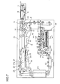
- Figure 7 shows the condition that feeding out the bills from the feed-out section 18 is completed.
- the sum total of the bills which can be deposited among the batch of bills inserted by the customer is displayed on the screen of an automatic teller machine, etc. disposed outside of the safe.
- the stage 34 moves to the lowest position and then slides.
- the bills accumulated on the stage 34 drop into the bill storage box 40 and are stored, which means the completion of a depositing operation (Steps #100 and #110).
- the bills in the rejected bill collecting section 14 are transported to the deposit/return port 4 through the bill transport path R and returned to the customer through the deposit/return port 4 (Step #120).
- the bills on the stage 34 are fed out by the feed mechanism 35 and transported to the rejected bill collecting section 14 through the direction diverting mechanism 33 and the bill returning path R' if the customer inputs the information of canceling the deposit by the operation panel. These bills are transported together with the rejected bills to the deposit/return port 4 through the bill transport path R and returned to the customer through the deposit/return port 4 (Steps #100, #130 and #140).
- the bill deposit machine 1 inputs and outputs bills through one and only deposit/return port 4. It is, therefore, possible that only the deposit/return port 4 is designed to face the outside with only one small opening on the wall of a solidly-built structure such as a safe. This makes it extremely difficult to break the bill deposit machine 1 and steal the bills inside, which means that the machine has further improved burglarproof features.
- the bill transport path R extending from the deposit/return port 4 to the feed-out section 18 is designed to transport the bills with the wide dimension of the bills parallel to the transport path horizontally and in a straight line. Therefore, the batch of bills is not curved, moreover, since the portion of the bill in contact with the transport mechanism is larger as compared with that in transporting bills with the narrow dimension of the bills parallel to the transport path, the bills are not easily separate from each other in the direction of transportation during transportation, enabling steady transportation.
- the bill deposit machine 1S also has a projection part 3S, a rectangular parallelepiped, which projects forward of the upper front face of the main body 2S of the machine.
- a deposit/return port 4S is disposed at the end of the projection part 3S.
- transport belts 5S and 6S are arranged to face each other in the upper and lower positions.
- the upper transport belt 5S can move vertically and can be freely in contact with and separate from the lower transport belt 6S.
- a bill conveying device 51 consists of the transport belts 5S and 6S. The batch of bills or a single bill inserted through the deposit/return port 4S is caught in the bill conveying device 51 and transported with the wide dimension of the bills parallel to the transport path horizontally and in a straight line.
- a batch accepting section 8S is disposed adjacent to the bill conveying device 51.
- a bill transport path RS which transports a batch of bills or a single bill with the wide dimension of the bills parallel to the transport path horizontally and in a straight line consists of the batch accepting section 8S and the bill conveying device 51.
- a rejected bill collecting section 14S is disposed below the batch accepting section 8S.
- a feed-out section 18S is disposed at the end of the bill transport path RS.
- the feed-out section 18S feeds out the bills, one at a time, out of the batch of bills received from the bill transport path RS and transports to a discriminating unit 28S.
- the denomination and the genuineness of the transported bill are discriminated by the discriminating unit 28S.
- the discriminated bills are transported to a direction diverting mechanism 33S through a transport section 52.
- the normal bills are transported to a temporary storage 32S and the rejected bills are transported to the rejected bill collecting section 14S by the direction diverting mechanism 33S.
- the sum total of the bills which can be deposited is displayed on the screen of an automatic teller machine, etc. disposed outside of the safe.
- the customer inputs the information of approving the amount of the deposit by the operation panel, the normal bills are taken out of the temporary storage 32S and dropped into a bill storage box 40S through the transport section 52S.
- the bill storage box 40S consists of two boxes, one for the main use and the other for the subordinate use. Or, these two boxes are used for storing the bills in different denominations separately.
- the rejected bills and even the normal bills which are not instructed to be deposited by the customer are transported to the deposit/return port 4S through the bill transport path RS and returned to the customer through the deposit/return port 4S.
- the bill deposit machine 1S has a thickness detecting device for detecting the thickness of the batch of bills and a takeout detecting device for detecting the movement of the bills which are being taken out of the deposit/return port 4S, both of which are disposed at the deposit/return port 4S.
- a thickness detecting device 60 will be described by referring to the drawings, Figure12 - Figure 14.
- the thickness detecting device 60 is comprised of the following elements: a lever 62 supported by a shaft 61 leveled with the projection part 3S to rotate vertically; a roller 63 which is supported to rotate freely at the movable end of the lever 62 and is in contact with the upper surface of the batch of bills inserted on the upper part of the transport belt 6S; a lever 64 fixed perpendicular to the lever 62; a spring 65, which is connected with the lever 64, for directing the levers 62 and 64 clockwise in the drawings; a solenoid 66, which is connected with the lever 64, for rotating the levers 62 and 64 counterclockwise against the spring 65 at the time of energizing; a light shield plate 67 fixed to the lever 62; a photo sensor 68 for monitoring the movement of the light shield plate 67; and an entrance sensor 69 for detecting the existence of bills at the deposit/return port 4S.
- the motion of the thickness detecting device 60 is described with reference to the flow chart in Figures 15.
- the lever 62 is always directed clockwise by the spring 65 and the angle is maintained where the lever 62 is in contact with a stopper (not illustrated). This usually makes the roller 63 at the raised position where the light shield plate 67 interrupts the photo sensor 68. This condition, which is shown in Figure 12, corresponds to the Step #201 in the flow chart in Figure 15.
- the entrance sensor 69 always monitors if the batch of bills or a bill is at the deposit/return port 4S (Step #202).
- the entrance sensor 69 detects the batch of bill B.P inserted at the deposit/return port 4S by the customer, that is, the entrance sensor 69 is in the status of interrupted light changed from in the status of received light
- the solenoid 66 is energized (Step #203) and rotates the lever 62 counterclockwise against the spring 65.
- the roller 63 goes down to be in contact with the upper surface of the batch of bills B.P. This is the condition shown in Figure 13.
- Step #204 Whether the roller 63 goes down lower than the specified value, that is, the thickness of the batch of bills B.P is within the permissible limit is determined by whether the photo sensor 68 is in the status of received light changed from in the status of interrupted light (Step #204).
- the Step #205 is conducted.
- the photo sensor 68 remains to be in the status of interrupted light because the roller 63 does not go down enough due to the excessively thick batch of bills B.P as shown in Figure 14, the Step #211 is conducted.
- Step #205 as the thickness of the batch of bill B.P is within the permissible limit, the batch of bills B.P is taken in by the bill conveying device 51. The batch of bills B.P is transported to the batch accepting section 8S.
- the entrance sensor 69 keeps on monitoring if the batch of bills B.P is at the deposit/return port 4S (Step #206).
- the entrance sensor 69 no longer detects the existence of the batch of bill B.P, that is, the entrance sensor 69 is in the status of received light changed from in the status of interrupted light, which means the completion of the intake of the batch of bills B.P, the bill conveying device 51 stops and the solenoid 66 is not energized (Step #207).
- the roller 63 goes up to be in the status of waiting (idling).
- the bill conveying device 51 rotates reversely and pushes the batch of bills B.P back to the customer.
- the reason why this is carried out is as follows. If the excessively thick batch of bills B.P is taken in, it falls like dominoes or falls and spreads as if a batch of cards is pushed from the side, during the transportation on the bill transport path RS, which causes the jam of bills. Whether the batch of bills B.P is taken out by the customer is determined by whether the entrance sensor 69 is in the status of received light changed from in the status of interrupted light (Step #212).
- Step #213 the motion of reverse transportation of bills continues for the specified period of time. Then, the bill conveying device 51 stops and the solenoid 66 is not energized (Step #214). The roller 63 goes up to be in the status of waiting (idling).
- the takeout detecting device 70 is comprised of the following elements added to the elements of the thickness detecting device 60.
- a plurality of transparent holes 71 are disposed at intervals of the same angle on the arc of the circle concentric with the center of rotation.
- the transparent holes 71 are six in number and disposed at intervals of sixty degrees.
- Photo sensor 72 shown in Figure 19 reads the movement of the transparent holes 71 and detects the rotation of the roller 63.
- the photo sensor 72 is of a photo-interrupter type having a light emitting part 72a and a light receiving part 72b.
- the rotation of the roller 63 is read by the arrival of the light emitted from the light emitting part 72a to the light receiving part 72b through the transparent holes 71 or by interrupting the light by the area between the transparent holes 71.
- the photo sensor 72 installed to the lever 62 moves up and down together with the roller 63.
- the motion of the takeout detecting device 70 and the motion of the bill conveying device 51 based on the motion of the former are described with reference to the flow chart in Figures 20.
- the lever 62 is directed clockwise by the spring 65 up to the position where the lever 62 is in contact with a stopper (not illustrated), and the roller 63 is at the raised position.
- the light shield plate 67 interrupts the photo sensor 68. This is the time when the rejected bills and the normal bills which are not instructed to be deposited by the customer are transported reversely on the bill transport path RS (Step #251).
- the entrance sensor 69 keeps on monitoring if the batch of bills or a bill reaches the deposit/return port 4S (Step #252).
- the entrance sensor 69 detects the arrival of the batch of bills or a bill, that is, the entrance sensor 69 is in the status of interrupted light changed from in the status of received light, the solenoid 66 is energized (Step #253) and rotates the lever 62 counterclockwise against the spring 65.
- the roller 63 goes down to be in contact with the upper surface of the batch of bills or a bill.
- the bill conveying device 51 keeps on transporting reversely for a while even after the entrance sensor 69 makes a signal, and then stops when the batch of bills or a bill projects out of the deposit/return port 4S to such an extent that the bills can be held between the fingers.
- This condition which is shown in Figure 16, corresponds to the Step #254.
- Figure 16 shows the condition of the projection of the batch of bills B.P, which has been transported reversely, from the deposit/retuning port 4S.
- the customer tries to hold and take out the batch of bills B.P according to the instruction (refer to Figure 17).
- the photo sensor 72 keeps on monitoring whether the roller 63 rotates (Step #255).
- the bill conveying device 51 further transports reversely the batch of bills B.P slightly to have said batch of bills B.P projected out of the deposit/return port 4S by the specified amount (Step #256). This is the condition of Figure 18.
- the specified amount means the length of the batch of bills B.P projecting out of the deposit/return port 4S which can be held by the fingers but does not drop off the deposit/return port 4S even if the customer releases his hold of the batch of bills B.P or the wind blows at the time of taking out the batch of bills B.P because the opposite side of the bills is caught between the transport belts 5S and 6S.
- the entrance sensor 69 keeps on monitoring if the batch of bills B.P is taken out of the deposit/return port 4S (Step #257).
- the entrance sensor 69 is in the status of received light changed from in the status of interrupted light, thus, the solenoid 66 is not energized (Step #258).
- the roller 63 goes up.
- the bill conveying device 51 transports reversely once again to completely clear the bill transport path RS (Step #259).
- the entrance sensor 69 keeps on monitoring if the bills reach the deposit/return port 4S (Step #260).
- the entrance sensor 69 detects the bills, which have not been taken out by the customer and are left on the bill transport path RS, transported reversely to the deposit/return port 4S, the next step goes back to the Step #253. If the entrance sensor 69 is not in the status of interrupted light even after the motion of reverse transportation of bills for the specified period of time, it is determined that the bill transport path RS is completely cleared, therefore, the reverse transportation is ended.
Landscapes
- Physics & Mathematics (AREA)
- General Physics & Mathematics (AREA)
- Engineering & Computer Science (AREA)
- Mechanical Engineering (AREA)
- Controlling Sheets Or Webs (AREA)
- Financial Or Insurance-Related Operations Such As Payment And Settlement (AREA)
Abstract
Description
- This invention relates to a bill deposit machine used in automatic teller machines, money-changing machines, etc.
- There is disclosed a bill deposit machine used in automatic teller machines, money-changing machines, etc. in Japanese Examined Patent Publication (Koukoku) No.63-19916. In the machine, a batch of bills is inserted into a deposit inlet by a customer. A feed-out section feeds out the bills, one at a time, out of the inserted batch of the bills. A discriminating unit determines if the bill fed out can be deposited or not. The bill determined as being able to be deposited is stored in a temporary storage. The bill stored in a temporary storage is stored in a safe if it is approved by the customer. On the other hand, the rejected bills determined by the discriminating unit as being unable to be deposited are transported to a return outlet and returned to the customer by way of the return outlet.
- In the above-mentioned bill deposit machine, as the deposit inlet and the return outlet were disposed separately and the mechanical strength of the area between the deposit inlet and the return outlet was not so high, the said area was sometimes broken by a bar, etc. inserted in the deposit inlet or the return outlet, with the result that the bills inside the machine were stolen.
- In view of such a problem, a method of handling bills is proposed, that is, a bill deposit machine to be accommodated inside a safe, and bills to be inputted and outputted through a single opening located on the wall of the safe.
- An object of the present invention is to provide a bill deposit machine with improved burglarproof features by following a method of handling bills to be inputted and outputted through a single opening at the same time with the steady transportation of bills. Another object of the present invention is to provide a bill deposit machine which can keep the bills to be returned until they are received by the customer. A further object of the present invention is to provide a bill deposit machine which assures a smooth depositing process without accepting a batch of bills over the maximum permissible limit in thickness.
- In order to achieve the above-mentioned object, the present invention is characterized by the following features. That is, the present invention is a bill deposit machine comprising: a deposit/return port for accepting and returning a batch of bills; a bill transport path for transporting the batch of bills accepted at said deposit/return port with the wide dimension of the bills parallel to the transport path horizontally and in a straight line; a feed-out section for feeding out the bills, one at a time, out of the batch of bills received from said bill transport path; a discriminating unit for discriminating if the bills fed out of said feed-out section can be deposited or not; and a bill returning path for transporting the rejected bills, which are determined by said discriminating unit as being unable to be deposited, to said bill transport path; wherein the bills are inputted and outputted by way of said deposit/return port. According to this feature, the bill deposit machine accommodated inside a safe is used with only the deposit/return port facing the outside of the safe through an opening located on a wall of the safe. Therefore, this makes it extremely difficult to break the machine and steal the bills, which means that the machine is highly burglarproof. In addition, the bill transport path which transports the bills inserted from the deposit/return port to the feed-out section is designed to transport a batch of bills or a bill with the wide dimension of the bills parallel to the transport path horizontally and in a straight line. Therefore, the batch of bills is not curved, moreover, since the area on the batch of bills contacted with a transport mechanism is large, the bills are not easily separate from each other in the direction of transportation during transportation, enabling steady transportation.
- Furthermore, in the present invention, a rejected bill collecting section is disposed on the way at said bill transport path to accumulate and temporarily store said rejected bills. According to this feature, the bills to be rejected can be returned together after the batch of bills is accepted at the deposit/return port.
- Furthermore, in the present invention, a temporary storage for temporarily storing the bills, which are determined by said discriminating unit as being able to be deposited, is disposed. The bills in said temporary storage are transported to said rejected bill collecting section when depositing transaction is cancelled. According to this feature, even the bills determined by the discriminating unit as being able to be deposited can be returned to the customer together with the rejected bills if the said bills are stopped from being deposited by the customer.
- Furthermore, in the present invention, said rejected bill collecting section, said feed-out section, said transport path for bills to be retuned and said bill transport path are disposed in a loop. According to this feature, the main elements can be disposed compactly in a rational manner.
- Furthermore, in the present invention, the rejected bills in said rejected bill collecting section are re-transported to said feed-out section to be discriminated by said discriminating unit. This feature enables the low probability of rejecting the bills which can be deposited. This reduces the labor of re-inserting the rejected bills by the customer into the deposit/return port to be discriminated once again.
- Furthermore, the present invention is also characterized by the following features. That is, the present invention is a bill deposit machine comprising: a deposit/return port for accepting and returning a batch of bills; a bill transport path for transporting the batch of bills accepted at said deposit/return port; a feed-out section for feeding out the bills, one at a time, out of the batch of bills received from said bill transport path; a discriminating unit for discriminating if the bills fed out of said feed-out section can be deposited or not; a bill returning path for transporting the rejected bills, which are determined by said discriminating unit as being unable to be deposited, to said bill transport path; a bill conveying device disposed at said deposit/return port; and a thickness detecting device for detecting the thickness of the batch of bills inserted into said deposit/return port; wherein the batch of bills is not taken in by said bill conveying device if it is detected to be over the specified value in thickness by said thickness detecting device. According to this feature, the bill deposit machine can prevent the batch of bills from falling like dominoes and spreading on the bill transport path as the result of the intake of the excessively thick batch of bills.
- Furthermore, the present invention is characterized by the following features. That is, the present invention is a bill deposit machine comprising: a deposit/return port for accepting and returning a batch of bills; a bill transport path for transporting the batch of bills accepted at said deposit/return port; a feed-out section for feeding out the bills, one at a time, out of the batch of bills received from said bill transport path; a discriminating unit for discriminating if the bills fed out of said feed-out section can be deposited or not; a bill returning path for transporting the rejected bills, which are determined by said discriminating unit as being unable to be deposited, to said bill transport path; a bill conveying device disposed at said deposit/return port; and a takeout detecting device for detecting the movement of the bills which are being taken out of said deposit/return port. When the movement of the bills which are being taken out of said deposit/return port is detected by said takeout detecting device, said bills are projected and kept to be projected from said deposit/return port by the specified amount by said bill conveying device. According to this feature, since the bills are projected from the deposit/return port by the specified length by the bill conveying device when they are about to be collected from the deposit/return port by the customer, takeout of the bills is easy. Even if the bills of different lengths are mixed in a batch, they can be surely handed to the customer. As the bills are maintained by the bill conveying device until they are taken out completely by the customer, they will neither drop nor be blown away by the wind.
- These and other objects, features of the present invention will be more clearly understood by the following description of the preferred embodiments of the invention in conjunction with the accompanying drawings, in which;
- Figure 1 is a perspective view showing the outline of the bill deposit machine in accordance with the first embodiment of the present invention;
- Figure 2 is a vertical sectional view of said bill deposit machine;
- Figure 3 is another vertical sectional view of said bill deposit machine showing the condition of a different motion;
- Figure 4 is another vertical sectional view of said bill deposit machine showing the condition of a further different motion;
- Figure 5 is another vertical sectional view of said bill deposit machine showing the condition of a further different motion;
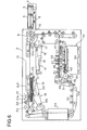
- Figure 6 is another vertical sectional view of said bill deposit machine showing the condition of a further different motion;
- Figure 7 is another vertical sectional view of said bill deposit machine showing the condition of a further different motion;
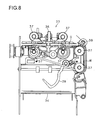
- Figure 8 is a sectional view taken along the line A-A in Figure 7;
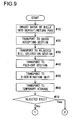
- Figure 9 is a flow chart showing a part of the procedure of the depositing operation performed by said bill deposit machine;
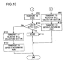
- Figure 10 is a flow chart showing the remaining part of the procedure of the depositing operation performed by the bill deposit machine; and
- Figure 11 is a vertical sectional view showing the outline of the bill deposit machine in accordance with the second embodiment of the present invention.
- Figure 12 is a partial vertical sectional view showing the structure of the thickness detecting device provided at the deposit/return port of the bill deposit machine in accordance with the second embodiment of the invention;
- Figure 13 is another partial vertical sectional view of said thickness detecting device showing the condition of a different motion;
- Figure 14 is another partial vertical sectional view of said thickness detecting device showing the condition of a further different motion;
- Figure 15 is a flow chart showing the operation sequence of said thickness detecting device;
- Figure 16 is a partial vertical sectional view showing the structure of the takeout detecting device provided at the deposit/return port of the bill deposit machine in accordance with the second embodiment of the invention;
- Figure 17 is another partial vertical sectional view of said takeout detecting device showing the condition of a different motion;
- Figure 18 is another partial vertical sectional view of said takeout detecting device showing the condition of a further different motion;
- Figure 19 is a schematic diagram showing the structure of said takeout detecting device in a section perpendicular to Fig. 16; and
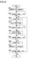
- Fig. 20 is a flow chart showing the operation sequence of said takeout detecting device.
-
- The first embodiment of the present invention will be described by referring to the drawings, Figure1 - Figure 10.
- As shown in Figure 1, the
bill deposit machine 1 according to the first embodiment has aprojection part 3, a rectangular parallelepiped, which projects forward of the upper front face of themain body 2 of the machine. A deposit/return port 4 is disposed at the end of theprojection part 3. The deposit/return port 4 is a slot long from side to side, which accepts and returns a batch of a plurality of bills in a stacking manner or a single bill in the direction of the wide dimension of the bills. Thebill deposit machine 1 is accommodated inside a safe and the deposit/return port 4 faces the outside of the safe through an opening located on the wall of the safe, which are not illustrated. - As shown in Figure 2, inside the
projection part 3,transport belts lower transport belt 6 can move vertically and can be freely in contact with and separate from theupper transport belt 5. A bill conveying device consists of thetransport belts return port 4 is sandwiched between thetransport belts - A
batch accepting section 8 is disposed adjacent to theprojection part 3 inside themain body 2 of the machine. Thebatch accepting section 8 has astage 9, apulley 10, a transport belt 11, animpeller 12, etc., all of which move up and down together. - Above the
batch accepting section 8, atransport belt 13 runs in the front and rear direction. Thebatch accepting section 8 can be freely in contact with and separate from the lower surface of the front end of thetransport belt 13. The batch of bills or a single bill transported into thebatch accepting section 8 by thetransport belts stage 9 and the transport belt 11, sandwiched between thetransport belts 11 and 13 and transported with the wide dimension of the bills parallel to the transport path horizontally and in a straight line. - The
impeller 12 has a plurality ofvanes 12a made of elastic material. The upper face of the rear end of the rejected bills supported by a rejectedbill collecting section 14 mentioned later is pressed by thevanes 12a so that the succeeding rejected bills can enter the rejectedbill collecting section 14 smoothly. - The rejected
bill collecting section 14 is disposed behind thebatch accepting section 8. The rejectedbill collecting section 14 has astage 15, atransport belt 16, etc. below thetransport belt 13. - The
stage 15 can move up and down and can be freely in contact with and separate from the lower surface of the middle part of thetransport belt 13. The upper surface of the rear end of thetransport belt 16 is almost the same in height as the upper surface of thestage 15. When thestage 15 moves up and down, thetransport belt 16 moves vertically using ashaft 17 located at the front end as a fulcrum and maintains the said state of being almost the same in height. The batch of bills or a single bill transported from thebatch accepting section 8 is supported horizontally by thestage 15 and thetransport belt 16, sandwiched between thetransport belts - A feed-out
section 18 is disposed behind the rejectedbill collecting section 14. The feed-outsection 18 has astage 19 and atransport belt 20, both located below thetransport belt 13, animpeller 21, akicker roller 22, afeed roller 23, areverse roller 24, etc. located behind thetransport belt 13. - The
stage 19 can move up and down and can be freely in contact with and separate from the lower surface of the rear end of thetransport belt 13. The upper surface of the front end of thetransport belt 20 is almost the same in height as the upper surface of thestage 19. When thestage 19 moves up and down, thetransport belt 20 moves vertically using ashaft 45 located at the rear end as a fulcrum and maintains the said state of being almost the same in height. The batch of bills or a single bill transported from the rejectedbill collecting section 14 is supported horizontally by thestage 19 and thetransport belt 20, sandwiched between thetransport belts - The
impeller 21 has a plurality ofvanes 21a made of elastic material. Theimpeller 21 rotates clockwise in the drawing and advances to the opposite side of the customer the only one bill accumulated on the top of the batch supported by thestage 19. Thekicker roller 22 and thefeed roller 23, which partly have highly frictional areas on each roller surface, rotate clockwise and transport the bills advanced by theimpeller 21 to the opposite side of the customer. Thereverse roller 24 rotates in the same rotating direction as thefeed roller 23 and prevents the bills other than the bill on the top of the batch from being fed out to the opposite side of the customer. - A
stopper 25 is disposed between the feed-outsection 18 and the rejectedbill collecting section 14. Thestopper 25 can either project into or retract from the bill transport path R (refer to Figure 4) consisting oftransport belts stopper 25 projects into the bill transport path R, it prevents bills from entering the feed-outsection 18. - When the batch of bills inserted from the deposit/
return port 4 is transported to the rejectedbill collecting section 14, a plurality of bills in the batch is sometimes separate from each other in the direction of transportation. Thestopper 25 projects into the bill transport path R when the sensor, which is not illustrated, detects the tip of a bill coming. This makes each bill sent into the rejectedbill collecting section 14 stop after being transported till the tip of each bill comes in contact with thestopper 25. Thus, the tips of the bills are arranged to be put in the same position so that the separate condition in the direction of transportation can be corrected. - A bill fed out of the feed-out
section 18 is sent to a discriminatingunit 28 bytransport belts unit 28 is sent to atemporary storage 32 by transport belts 29 - 31. Thetemporary storage 32 has adirection diverting mechanism 33, astage 34, afeed mechanism 35, etc. - As shown in Figure 8, the
direction diverting mechanism 33 has a widedimension transport roller 36, a narrowdimension transport roller 37, a drivenroller 38, astopper 39, etc. When a bill is transported from the discriminatingunit 28 into an empty space G, thedirection diverting mechanism 33 makes the bill transported in a rightward direction in Figure 8 by the narrowdimension transport roller 37 and passing in a path W if the bill is the one which can be deposited (hereinafter referred to as a normal bill). This makes the bill drop upside down on thestage 34. - The
stopper 39 is to press the upper face of the bills placed on thestage 34 so that the bills may not obstruct the succeeding bills to be transported to thestage 34. The bill transported to thestage 34 pushes thestopper 39 up and accumulates on thestage 34. Thestage 34 can move up and down. Below thestage 34, a bill storage box 40 (refer to Figure 1) which is attachable and detachable to themain body 2 of the machine is disposed. When a customer inputs the information of approving the amount of the deposit by the operation panel (not illustrated) of an automatic teller machine etc., thestage 34 slides so that the bills accumulated on thestage 34 can drop into thebill storage box 40. - If a bill is the one which can not be deposited (hereinafter referred to as a rejected bill), the
direction diverting mechanism 33 makes the bill transported forward of themain body 2 of the machine (in a rightward direction in Figure 2) by the widedimension transport roller 36. The bill is transported to the rejectedbill collecting section 14 through a bill returning path R' (refer to Figure 4) consisting of atransport belt 41, the transport belt 11, etc. - A
feed mechanism 35 has akicker roller 42, afeed roller 43, areverse roller 44, etc. Thekicker roller 42 and thefeed roller 43, which partly have highly frictional areas on each roller surface, rotate clockwise. Thekicker roller 42 feeds out the bills accumulated on thestage 34 one at a time from the top of the batch. The bills fed out by akicker roller 42 are transported to the place betweentransport rollers feed roller 43. Thereverse roller 44 rotates reversely only for a period in the latter half of the rotating period while thefeed roller 43 is rotting, and prevents the succeeding bills from being caught. - Now described is the motion of the
bill deposit machine 1 according to the first embodiment with reference to the flow charts in Figures 9 and 10. When a customer inserts a batch of bills in the direction of the wide dimension of the bills into the deposit/return port 4 (Step #10) in the condition as shown in Figure 2, the front end of thetransport belt 6 goes down and thebatch accepting section 8 moves to the lower end position, as shown in Figure 3. The batch of bills is, then, sandwiched between thetransport belts batch accepting section 8 by rotating thetransport belts 5 and 6 (Step #20). - When the front end of the batch of bills comes to the
batch accepting section 8, thebatch accepting section 8 is raised as shown in Figure 4. This makes the batch of bills B.P sandwiched between thetransport belts 11 and 13. Thestage 15 in the rejectedbill collecting section 14 moves to the middle position. The batch of bills B.P is, then, transported to the rejectedbill collecting section 14 with thetransport belts 11 and 13 running (Step #30). - When the batch of bills B.P comes to the rejected
bill collecting section 14, thestage 15 is raised as shown in Figure 5. This makes the batch of bills B.P sandwiched between thetransport belts stopper 25 then retracts from the transport path and the batch of bills B.P is transported to the feed-outsection 18 with thetransport belts - When the batch of bills B.P comes on about the half way to the specified position at the feed-out
section 18, thestage 19 is raised. This makes the batch of bills B.P sandwiched between thetransport belts transport belts stage 19 goes down, then goes up once again and stops at the height suitable for feeding out as shown in Figure 6. Thebatch accepting section 8 moves to the higher end position, thestage 15 moves downward and thestopper 25 projects into the transport path. - The bill accumulated on the top of the batch of bills B.P is advanced to the opposite side of the customer with the
impeller 21 rotating. The bill is transported toward thetransport belts kicker roller 22 and thefeed roller 23 rotating, when thereverse roller 24 prevents the bills other than the bill on the top of the batch from being fed out. The bill is transported to the discriminatingunit 28 bytransport belts 26 and 27 (Step #50). - The discriminating
unit 28 discriminates the denomination and the genuineness of the transported bill, of which result is stored in the memory of the control means. The bill which has passed through the discriminatingunit 28 is transported to thetemporary storage 32 by the transport belts 29 - 31 (Step #60). If the transported bill is a normal bill, thedirection diverting mechanism 33 makes the bill transported to be on thestage 34 by the narrow dimension transport roller 37 (Steps # 70 and #80). - If the bill transported to the
temporary storage 32 is a rejected bill, thedirection diverting mechanism 33 makes the bill transported forward of themain body 2 of the machine by the widedimension transport roller 36. The bill is transported to the rejectedbill collecting section 14 through the bill returning path R' (Steps # 70 and #90). Figure 7 shows the condition that feeding out the bills from the feed-outsection 18 is completed. - The sum total of the bills which can be deposited among the batch of bills inserted by the customer is displayed on the screen of an automatic teller machine, etc. disposed outside of the safe. When the customer inputs the information of approving the amount of the deposit by the operation panel, the
stage 34 moves to the lowest position and then slides. The bills accumulated on thestage 34 drop into thebill storage box 40 and are stored, which means the completion of a depositing operation (Steps #100 and #110). On the other hand, the bills in the rejectedbill collecting section 14 are transported to the deposit/return port 4 through the bill transport path R and returned to the customer through the deposit/return port 4 (Step #120). - When the amount of the bills which can be deposited is displayed on the screen of an automatic teller machine etc., the bills on the
stage 34 are fed out by thefeed mechanism 35 and transported to the rejectedbill collecting section 14 through thedirection diverting mechanism 33 and the bill returning path R' if the customer inputs the information of canceling the deposit by the operation panel. These bills are transported together with the rejected bills to the deposit/return port 4 through the bill transport path R and returned to the customer through the deposit/return port 4 (Steps #100, #130 and #140). - The
bill deposit machine 1 according to the first embodiment inputs and outputs bills through one and only deposit/return port 4. It is, therefore, possible that only the deposit/return port 4 is designed to face the outside with only one small opening on the wall of a solidly-built structure such as a safe. This makes it extremely difficult to break thebill deposit machine 1 and steal the bills inside, which means that the machine has further improved burglarproof features. - In addition, in the
bill deposit machine 1, the bill transport path R extending from the deposit/return port 4 to the feed-outsection 18 is designed to transport the bills with the wide dimension of the bills parallel to the transport path horizontally and in a straight line. Therefore, the batch of bills is not curved, moreover, since the portion of the bill in contact with the transport mechanism is larger as compared with that in transporting bills with the narrow dimension of the bills parallel to the transport path, the bills are not easily separate from each other in the direction of transportation during transportation, enabling steady transportation. - It is also possible to transport the rejected bills in the rejected
bill collecting section 14 to the feed-outsection 18 once again to discriminate in the discriminatingunit 28. If this is put into practice, there are cases where the rejected bill is determined to be a normal bill at the second discrimination, thus, the possibility of rejecting the bills which can be deposited decreases. This eliminates the labor of inserting the rejected bills into the deposit/return port 4 once again by the customer for the purpose of discrimination. - The above explanation is given as to depositing the batch of bills. The same holds true with regard to depositing a single bill.
- In the next place, the second embodiment of the present invention will be described by referring to the drawings, Figure11 - Figure 20. The basic constitution of the bill deposit machine according to the second embodiment does not greatly differ from that of the first embodiment. Only the differences between these two embodiments are the spatial dispositions of element blocks and the detailed structures. Therefore, the same numbers as used in the first embodiment are assigned to the constituent elements of the second embodiment when the constituent elements of the second embodiment are in common with those of the first embodiment in function and working. This can make the correspondence between the first and the second embodiments found easily. Letter 'S' which means 'second' is prefixed to each number so that the second embodiment can be differentiated from the first embodiment.
- The
bill deposit machine 1S according to the second embodiment also has aprojection part 3S, a rectangular parallelepiped, which projects forward of the upper front face of themain body 2S of the machine. A deposit/return port 4S is disposed at the end of theprojection part 3S. Inside theprojection part 3S,transport belts upper transport belt 5S can move vertically and can be freely in contact with and separate from thelower transport belt 6S. Abill conveying device 51 consists of thetransport belts return port 4S is caught in thebill conveying device 51 and transported with the wide dimension of the bills parallel to the transport path horizontally and in a straight line. - Inside the
main body 2S of the machine, abatch accepting section 8S is disposed adjacent to thebill conveying device 51. A bill transport path RS which transports a batch of bills or a single bill with the wide dimension of the bills parallel to the transport path horizontally and in a straight line consists of thebatch accepting section 8S and thebill conveying device 51. Below thebatch accepting section 8S, a rejectedbill collecting section 14S is disposed. - A feed-out
section 18S is disposed at the end of the bill transport path RS. The feed-outsection 18S feeds out the bills, one at a time, out of the batch of bills received from the bill transport path RS and transports to a discriminatingunit 28S. - The denomination and the genuineness of the transported bill are discriminated by the discriminating
unit 28S. The discriminated bills are transported to adirection diverting mechanism 33S through atransport section 52. The normal bills are transported to atemporary storage 32S and the rejected bills are transported to the rejectedbill collecting section 14S by thedirection diverting mechanism 33S. - When the discrimination of the batch of bills inserted by the customer is completely finished, the sum total of the bills which can be deposited is displayed on the screen of an automatic teller machine, etc. disposed outside of the safe. When the customer inputs the information of approving the amount of the deposit by the operation panel, the normal bills are taken out of the
temporary storage 32S and dropped into abill storage box 40S through the transport section 52S. Thebill storage box 40S consists of two boxes, one for the main use and the other for the subordinate use. Or, these two boxes are used for storing the bills in different denominations separately. - The rejected bills and even the normal bills which are not instructed to be deposited by the customer are transported to the deposit/
return port 4S through the bill transport path RS and returned to the customer through the deposit/return port 4S. - The
bill deposit machine 1S according to the second embodiment has a thickness detecting device for detecting the thickness of the batch of bills and a takeout detecting device for detecting the movement of the bills which are being taken out of the deposit/return port 4S, both of which are disposed at the deposit/return port 4S. - A
thickness detecting device 60 will be described by referring to the drawings, Figure12 - Figure 14. Thethickness detecting device 60 is comprised of the following elements: alever 62 supported by ashaft 61 leveled with theprojection part 3S to rotate vertically; aroller 63 which is supported to rotate freely at the movable end of thelever 62 and is in contact with the upper surface of the batch of bills inserted on the upper part of thetransport belt 6S; alever 64 fixed perpendicular to thelever 62; aspring 65, which is connected with thelever 64, for directing thelevers solenoid 66, which is connected with thelever 64, for rotating thelevers spring 65 at the time of energizing; alight shield plate 67 fixed to thelever 62; aphoto sensor 68 for monitoring the movement of thelight shield plate 67; and anentrance sensor 69 for detecting the existence of bills at the deposit/return port 4S. Thephoto sensor 68 can either be of a transparent (photo-interrupter) type or of a reflective type. Theentrance sensor 69 is a photo-interrupter type of photo sensor having a light emitting part and a light receiving part. - The motion of the
thickness detecting device 60 is described with reference to the flow chart in Figures 15. Thelever 62 is always directed clockwise by thespring 65 and the angle is maintained where thelever 62 is in contact with a stopper (not illustrated). This usually makes theroller 63 at the raised position where thelight shield plate 67 interrupts thephoto sensor 68. This condition, which is shown in Figure 12, corresponds to theStep # 201 in the flow chart in Figure 15. - The
entrance sensor 69 always monitors if the batch of bills or a bill is at the deposit/return port 4S (Step #202). When theentrance sensor 69 detects the batch of bill B.P inserted at the deposit/return port 4S by the customer, that is, theentrance sensor 69 is in the status of interrupted light changed from in the status of received light, thesolenoid 66 is energized (Step #203) and rotates thelever 62 counterclockwise against thespring 65. Theroller 63 goes down to be in contact with the upper surface of the batch of bills B.P. This is the condition shown in Figure 13. - Whether the
roller 63 goes down lower than the specified value, that is, the thickness of the batch of bills B.P is within the permissible limit is determined by whether thephoto sensor 68 is in the status of received light changed from in the status of interrupted light (Step #204). When thephoto sensor 68 is in the status of received light because thelight shield plate 67 is out of the ray of thephoto sensor 68 as shown in Figure 13, theStep # 205 is conducted. When thephoto sensor 68 remains to be in the status of interrupted light because theroller 63 does not go down enough due to the excessively thick batch of bills B.P as shown in Figure 14, theStep # 211 is conducted. - In the
Step # 205, as the thickness of the batch of bill B.P is within the permissible limit, the batch of bills B.P is taken in by thebill conveying device 51. The batch of bills B.P is transported to thebatch accepting section 8S. - The
entrance sensor 69 keeps on monitoring if the batch of bills B.P is at the deposit/return port 4S (Step #206). When theentrance sensor 69 no longer detects the existence of the batch of bill B.P, that is, theentrance sensor 69 is in the status of received light changed from in the status of interrupted light, which means the completion of the intake of the batch of bills B.P, thebill conveying device 51 stops and thesolenoid 66 is not energized (Step #207). Theroller 63 goes up to be in the status of waiting (idling). - If the batch of bills B.P is excessively thick and the
Step # 211 is conducted, thebill conveying device 51 rotates reversely and pushes the batch of bills B.P back to the customer. The reason why this is carried out is as follows. If the excessively thick batch of bills B.P is taken in, it falls like dominoes or falls and spreads as if a batch of cards is pushed from the side, during the transportation on the bill transport path RS, which causes the jam of bills. Whether the batch of bills B.P is taken out by the customer is determined by whether theentrance sensor 69 is in the status of received light changed from in the status of interrupted light (Step #212). In order to completely sweep out the bills which may be left on the transport path RS even after the batch of bills B.P is taken out, the motion of reverse transportation of bills continues for the specified period of time (Step #213). Then, thebill conveying device 51 stops and thesolenoid 66 is not energized (Step #214). Theroller 63 goes up to be in the status of waiting (idling). - Now described is a
takeout detecting device 70 with reference to the drawings, Figures 16 - 19. Thetakeout detecting device 70 is comprised of the following elements added to the elements of thethickness detecting device 60. On theroller 63, a plurality oftransparent holes 71 are disposed at intervals of the same angle on the arc of the circle concentric with the center of rotation. In the example in the drawing, thetransparent holes 71 are six in number and disposed at intervals of sixty degrees.Photo sensor 72 shown in Figure 19 reads the movement of thetransparent holes 71 and detects the rotation of theroller 63. Thephoto sensor 72 is of a photo-interrupter type having alight emitting part 72a and alight receiving part 72b. The rotation of theroller 63 is read by the arrival of the light emitted from thelight emitting part 72a to thelight receiving part 72b through thetransparent holes 71 or by interrupting the light by the area between the transparent holes 71. Thephoto sensor 72 installed to thelever 62 moves up and down together with theroller 63. - The motion of the
takeout detecting device 70 and the motion of thebill conveying device 51 based on the motion of the former are described with reference to the flow chart in Figures 20. As mentioned earlier, thelever 62 is directed clockwise by thespring 65 up to the position where thelever 62 is in contact with a stopper (not illustrated), and theroller 63 is at the raised position. Thelight shield plate 67 interrupts thephoto sensor 68. This is the time when the rejected bills and the normal bills which are not instructed to be deposited by the customer are transported reversely on the bill transport path RS (Step #251). - The
entrance sensor 69 keeps on monitoring if the batch of bills or a bill reaches the deposit/return port 4S (Step #252). When theentrance sensor 69 detects the arrival of the batch of bills or a bill, that is, theentrance sensor 69 is in the status of interrupted light changed from in the status of received light, thesolenoid 66 is energized (Step #253) and rotates thelever 62 counterclockwise against thespring 65. Theroller 63 goes down to be in contact with the upper surface of the batch of bills or a bill. Thebill conveying device 51 keeps on transporting reversely for a while even after theentrance sensor 69 makes a signal, and then stops when the batch of bills or a bill projects out of the deposit/return port 4S to such an extent that the bills can be held between the fingers. This condition, which is shown in Figure 16, corresponds to theStep # 254. Figure 16 shows the condition of the projection of the batch of bills B.P, which has been transported reversely, from the deposit/retuningport 4S. - As the instruction of taking out the bills is displayed on the screen of an automatic teller machine, etc. accommodating the
bill deposit machine 1, the customer tries to hold and take out the batch of bills B.P according to the instruction (refer to Figure 17). Thephoto sensor 72 keeps on monitoring whether theroller 63 rotates (Step #255). When thephoto sensor 72 detects theroller 63 rotating as the batch of bills B.P moves, thebill conveying device 51 further transports reversely the batch of bills B.P slightly to have said batch of bills B.P projected out of the deposit/return port 4S by the specified amount (Step #256). This is the condition of Figure 18. The specified amount means the length of the batch of bills B.P projecting out of the deposit/return port 4S which can be held by the fingers but does not drop off the deposit/return port 4S even if the customer releases his hold of the batch of bills B.P or the wind blows at the time of taking out the batch of bills B.P because the opposite side of the bills is caught between thetransport belts - The
entrance sensor 69 keeps on monitoring if the batch of bills B.P is taken out of the deposit/return port 4S (Step #257). When the batch of bills B.P is taken out by the customer at the time of the condition shown in Figure 18, theentrance sensor 69 is in the status of received light changed from in the status of interrupted light, thus, thesolenoid 66 is not energized (Step #258). Theroller 63 goes up. - Then, the
bill conveying device 51 transports reversely once again to completely clear the bill transport path RS (Step #259). Theentrance sensor 69 keeps on monitoring if the bills reach the deposit/return port 4S (Step #260). When theentrance sensor 69 detects the bills, which have not been taken out by the customer and are left on the bill transport path RS, transported reversely to the deposit/return port 4S, the next step goes back to theStep # 253. If theentrance sensor 69 is not in the status of interrupted light even after the motion of reverse transportation of bills for the specified period of time, it is determined that the bill transport path RS is completely cleared, therefore, the reverse transportation is ended. - It is to be understood that this invention is not limited to the described embodiment and modifications and variations of the invention may be made without departing from the spirit and scope of the invention.
Claims (7)
- A bill deposit machine comprising:wherein the bills are inputted and outputted by way of said deposit/return port.a deposit/return port for accepting and returning a batch of bills;a bill transport path for transporting the batch of bills accepted at said deposit/return port with the wide dimension of the bills parallel to the transport path horizontally and in a straight line;a feed-out section at the end of said bill transport path for feeding out the bills, one at a time, out of the batch of bills received from said bill transport path;a discriminating unit for discriminating if the bills fed out of said feed-out section can be deposited or not; anda bill returning path for transporting to said bill transport path the rejected bills determined by said discriminating unit as being unable to be deposited;
- A bill deposit machine according to claim 1, wherein a rejected bill collecting section is disposed on the way at said bill transport path to accumulate and temporarily store said rejected bills.
- A bill deposit machine according to claim 2, wherein a temporary storage is provided to temporarily store the bills determined by said discriminating unit as being able to be deposited, and the bills in said temporary storage are transported to said rejected bill collecting section when depositing transaction is cancelled.
- A bill deposit machine according to claim 2, wherein said rejected bill collecting section, said feed-out section, said bill returning path, and said bill transport path are disposed in a loop.
- A bill deposit machine according to claim 2, wherein the rejected bills in said rejected bill collecting section are re-transported to said feed-out section to be discriminated by said discriminating unit.
- A bill deposit machine comprising:wherein the batch of bills is not taken in by said bill conveying device if the batch of bills is detected to be over the specified value in thickness by said thickness detecting device.a deposit/return port for accepting and returning a batch of bills;a bill transport path for transporting the batch of bills accepted at said deposit/return port;a feed-out section for feeding out the bills, one at a time, out of the batch of bills received from said bill transport path;a discriminating unit for discriminating if the bills fed out of said feed-out section can be deposited or not;a bill returning path for transporting to said bill transport path the rejected bills determined by said discriminating unit as being unable to be deposited;a bill conveying device at said deposit/return port; anda thickness detecting device for detecting the thickness of the batch of bills inserted into said deposit/return port;
- A bill deposit machine comprising:wherein, said bills are projected and kept to be projected out of said deposit/return port by the specified amount by said bill conveying device when the movement of said bills which are being taken out of said deposit/return port is detected by said takeout detecting device.a deposit/return port for accepting and returning a batch of bills;a bill transport path for transporting the batch of bills accepted at said deposit/return port;a feed-out section for feeding out the bill, one at a time, out of the batch of bills received from said bill transport path;a discriminating unit for discriminating if the bills fed out of said feed-out section can be deposited or not;a bill returning path for transporting to said bill transport path the rejected bills determined by said discriminating unit as being unable to be deposited;a bill conveying device at said deposit/return port; anda takeout detecting device for detecting the movement of the bills at said deposit/return port;
Applications Claiming Priority (2)
| Application Number | Priority Date | Filing Date | Title |
|---|---|---|---|
| JP2001356887A JP4007799B2 (en) | 2001-11-22 | 2001-11-22 | Banknote deposit device |
| JP2001356887 | 2001-11-22 |
Publications (2)
| Publication Number | Publication Date |
|---|---|
| EP1315127A2 true EP1315127A2 (en) | 2003-05-28 |
| EP1315127A3 EP1315127A3 (en) | 2003-10-29 |
Family
ID=19168325
Family Applications (1)
| Application Number | Title | Priority Date | Filing Date |
|---|---|---|---|
| EP02025948A Withdrawn EP1315127A3 (en) | 2001-11-22 | 2002-11-20 | Bill deposit machine |
Country Status (4)
| Country | Link |
|---|---|
| US (1) | US7849992B2 (en) |
| EP (1) | EP1315127A3 (en) |
| JP (1) | JP4007799B2 (en) |
| CN (1) | CN1204534C (en) |
Cited By (5)
| Publication number | Priority date | Publication date | Assignee | Title |
|---|---|---|---|---|
| EP1598791A3 (en) * | 2004-05-19 | 2006-03-22 | Ncr International Inc. | Self-service terminal |
| EP2259233A4 (en) * | 2008-03-26 | 2011-05-11 | Glory Kogyo Kk | APPARATUS FOR HANDLING PAPER NOTES AND METHOD FOR HANDLING PAPER NOTES |
| EP1732046A4 (en) * | 2004-03-12 | 2011-05-11 | Fujitsu Ltd | DEVICE FOR HANDLING PAPER SHEETS OR OTHERWISE, AUTOMATIC TRANSACTION DEVICE AND DEVICE FOR TRANSPORTING PAPER SHEETS OR OTHER |
| EP2320392A1 (en) * | 2009-02-25 | 2011-05-11 | Hitachi-Omron Terminal Solutions, Corp. | Paper sheet handling machine |
| CN103136847A (en) * | 2011-11-29 | 2013-06-05 | 恒银金融科技有限公司 | Friction separation conveying device of automatic teller machine (ATM) |
Families Citing this family (29)
| Publication number | Priority date | Publication date | Assignee | Title |
|---|---|---|---|---|
| US7422118B2 (en) * | 2003-12-16 | 2008-09-09 | Cts Cashpro, S.P.A. | Equipment for the automatic deposit of banknotes |
| JP4174442B2 (en) * | 2004-03-15 | 2008-10-29 | 富士通株式会社 | Paper sheet bundle height detection method and paper sheet handling apparatus |
| JP2006143384A (en) | 2004-11-18 | 2006-06-08 | Aruze Corp | Banknote handling device and banknote storage unit |
| US7559461B2 (en) * | 2006-06-02 | 2009-07-14 | First Data Corporation | ATM systems and methods for cashing checks |
| DE102006028632A1 (en) * | 2006-06-22 | 2007-12-27 | Giesecke & Devrient Gmbh | Processing device for value documents |
| JPWO2008139584A1 (en) * | 2007-05-10 | 2010-07-29 | グローリー株式会社 | Banknote handling equipment |
| JP5220385B2 (en) | 2007-11-02 | 2013-06-26 | 日立オムロンターミナルソリューションズ株式会社 | Banknote deposit and withdrawal mechanism and automatic cash transaction equipment |
| WO2009122508A1 (en) * | 2008-03-31 | 2009-10-08 | グローリー株式会社 | Paper note handling unit, paper note handling method, and paper note handling machine |
| DE102008030878A1 (en) * | 2008-06-30 | 2009-12-31 | Giesecke & Devrient Gmbh | Apparatus and method for accepting or dispensing banknotes |
| US7900900B2 (en) | 2008-07-08 | 2011-03-08 | Glory Ltd. | Sheet handling device and sheet handling method |
| JP5266918B2 (en) * | 2008-07-10 | 2013-08-21 | 沖電気工業株式会社 | Medium separation method and medium separation structure |
| WO2010097954A1 (en) * | 2009-02-27 | 2010-09-02 | グローリー株式会社 | Device for sorting- and binding-processing of banknotes |
| JP5308216B2 (en) * | 2009-04-06 | 2013-10-09 | 日立オムロンターミナルソリューションズ株式会社 | Paper sheet handling equipment |
| JP5463748B2 (en) * | 2009-06-16 | 2014-04-09 | 沖電気工業株式会社 | Media processing device |
| JP5267351B2 (en) * | 2009-06-24 | 2013-08-21 | 沖電気工業株式会社 | Banknote deposit and withdrawal machine |
| KR101888572B1 (en) * | 2012-12-31 | 2018-09-20 | 효성티앤에스 주식회사 | Medium separating apparatus for automatic teller machine |
| JP5615953B2 (en) * | 2013-03-06 | 2014-10-29 | 日立オムロンターミナルソリューションズ株式会社 | Banknote deposit and withdrawal mechanism and automatic cash transaction equipment |
| JP5564127B2 (en) * | 2013-03-06 | 2014-07-30 | 日立オムロンターミナルソリューションズ株式会社 | Banknote deposit and withdrawal mechanism and automatic cash transaction equipment |
| JP5879371B2 (en) * | 2013-04-19 | 2016-03-08 | 株式会社ユニバーサルエンターテインメント | Paper sheet processing device and game medium lending device |
| JP5857078B2 (en) * | 2013-04-19 | 2016-02-10 | 株式会社ユニバーサルエンターテインメント | Paper sheet processing device and game medium lending device |
| JP5857080B2 (en) * | 2013-04-19 | 2016-02-10 | 株式会社ユニバーサルエンターテインメント | Paper sheet processing device and game medium lending device |
| JP5857077B2 (en) * | 2013-04-19 | 2016-02-10 | 株式会社ユニバーサルエンターテインメント | Paper sheet processing device and game medium lending device |
| US9082246B2 (en) * | 2013-07-31 | 2015-07-14 | Ncr Corporation | Media item transportation |
| US10504315B2 (en) * | 2013-08-05 | 2019-12-10 | Ncr Corporation | Clamping of media items |
| US9396619B2 (en) * | 2013-12-06 | 2016-07-19 | Nautilus Hyosung Inc. | Apparatus for receiving cash and checks |
| KR102120963B1 (en) * | 2013-12-06 | 2020-06-09 | 효성티앤에스 주식회사 | Automatic teller machine |
| KR101729389B1 (en) | 2015-04-23 | 2017-05-02 | 주식회사 엘지씨엔에스 | Financial device |
| KR102806917B1 (en) * | 2019-11-25 | 2025-05-13 | 효성티앤에스 주식회사 | Automatic teller machine and control method thereof |
| CN114347046B (en) * | 2020-10-12 | 2024-07-26 | 航天信息股份有限公司 | Automatic bill reimbursement equipment |
Citations (2)
| Publication number | Priority date | Publication date | Assignee | Title |
|---|---|---|---|---|
| WO1999028225A1 (en) * | 1997-11-28 | 1999-06-10 | Diebold, Incorporated | Document alignment mechanism for currency recycling automated banking machine |
| EP0936580A2 (en) * | 1998-02-17 | 1999-08-18 | Fujitsu Limited | Automatic teller machine |
Family Cites Families (18)
| Publication number | Priority date | Publication date | Assignee | Title |
|---|---|---|---|---|
| JPS57121761A (en) * | 1981-01-22 | 1982-07-29 | Toshiba Corp | Automatic transaction device of currency |
| SE8104036L (en) * | 1981-06-29 | 1982-12-30 | Leif Lundblad | AUTOMATIC FOR SECURITIES AND OTHER DOCUMENTS LIKE banknotes, checks, receipts, notes etc. |
| JPS60131077U (en) | 1984-02-10 | 1985-09-02 | オムロン株式会社 | Bulk injection type building checker |
| US4726474A (en) * | 1984-05-08 | 1988-02-23 | Laurel Bank Machines Co., Ltd. | Circulating-type bill depositing and disbursing machine |
| DE3447236A1 (en) * | 1984-12-22 | 1986-07-03 | Professor Alfred Krauth Apparatebau GmbH & Co KG, 6930 Eberbach | ISSUER FOR INDIVIDUAL ISSUE OF BANKNOTES |
| US4733765A (en) * | 1985-11-14 | 1988-03-29 | Kabushiki Kaisha Toshiba | Cash handling machine for handling mixtures of notes and coins introduced together |
| US4696426A (en) * | 1986-05-30 | 1987-09-29 | Ibm Corporation | Document reading envelope depository |
| JP3204967B2 (en) * | 1990-08-29 | 2001-09-04 | 株式会社日立製作所 | Paper sheet management device and cash automatic transaction device |
| US5695038A (en) * | 1995-07-24 | 1997-12-09 | Brink's, Incorporated | Drop safe |
| JP3086167B2 (en) | 1996-02-29 | 2000-09-11 | ローレルバンクマシン株式会社 | Banknote handling machine |
| GB9621501D0 (en) * | 1996-10-15 | 1996-12-04 | Ncr Int Inc | Improved ATM |
| US6273413B1 (en) * | 1997-11-28 | 2001-08-14 | Diebold, Incorporated | Automated banking machine with sheet directing apparatus |
| JP3399761B2 (en) | 1996-12-26 | 2003-04-21 | ローレルバンクマシン株式会社 | Banknote handling machine |
| DE19814694A1 (en) * | 1997-04-08 | 1998-10-15 | Fuji Electric Co Ltd | Banknote input device for automatic transaction device |
| GB9726836D0 (en) * | 1997-12-20 | 1998-02-18 | Ncr Int Inc | Improvements in and relating to a machine for dispensing media |
| USD441400S1 (en) * | 1998-03-05 | 2001-05-01 | Bally Gaming, Inc. | Bill dispenser |
| KR100330326B1 (en) * | 1998-10-12 | 2002-04-01 | 가나이 쓰토무 | A Paper Money Paying-in and Paying-out Device |
| AR031076A1 (en) * | 1999-09-21 | 2003-09-10 | Diebold Inc | MA QUICA AUTOMA TICA FOR TRANSACTIONS |
-
2001
- 2001-11-22 JP JP2001356887A patent/JP4007799B2/en not_active Expired - Fee Related
-
2002
- 2002-11-20 EP EP02025948A patent/EP1315127A3/en not_active Withdrawn
- 2002-11-22 CN CNB02160231XA patent/CN1204534C/en not_active Expired - Fee Related
- 2002-11-22 US US10/301,717 patent/US7849992B2/en not_active Expired - Fee Related
Patent Citations (2)
| Publication number | Priority date | Publication date | Assignee | Title |
|---|---|---|---|---|
| WO1999028225A1 (en) * | 1997-11-28 | 1999-06-10 | Diebold, Incorporated | Document alignment mechanism for currency recycling automated banking machine |
| EP0936580A2 (en) * | 1998-02-17 | 1999-08-18 | Fujitsu Limited | Automatic teller machine |
Cited By (10)
| Publication number | Priority date | Publication date | Assignee | Title |
|---|---|---|---|---|
| EP1732046A4 (en) * | 2004-03-12 | 2011-05-11 | Fujitsu Ltd | DEVICE FOR HANDLING PAPER SHEETS OR OTHERWISE, AUTOMATIC TRANSACTION DEVICE AND DEVICE FOR TRANSPORTING PAPER SHEETS OR OTHER |
| EP1598791A3 (en) * | 2004-05-19 | 2006-03-22 | Ncr International Inc. | Self-service terminal |
| US7347359B2 (en) | 2004-05-19 | 2008-03-25 | Ncr Corporation | Self-service terminal |
| EP2259233A4 (en) * | 2008-03-26 | 2011-05-11 | Glory Kogyo Kk | APPARATUS FOR HANDLING PAPER NOTES AND METHOD FOR HANDLING PAPER NOTES |
| US8276901B2 (en) | 2008-03-26 | 2012-10-02 | Glory Ltd. | Paper sheet handling apparatus and paper sheet handling method |
| EP2320392A1 (en) * | 2009-02-25 | 2011-05-11 | Hitachi-Omron Terminal Solutions, Corp. | Paper sheet handling machine |
| CN101814208B (en) * | 2009-02-25 | 2013-06-05 | 日立欧姆龙金融系统有限公司 | Paper handling device |
| US8556251B2 (en) | 2009-02-25 | 2013-10-15 | Hitachi Omron Terminal Solutions, Corp. | Paper sheet handling machine with moving plates and conveyor assemblies |
| CN103136847A (en) * | 2011-11-29 | 2013-06-05 | 恒银金融科技有限公司 | Friction separation conveying device of automatic teller machine (ATM) |
| CN103136847B (en) * | 2011-11-29 | 2015-01-21 | 恒银金融科技有限公司 | Friction separation conveying device of automatic teller machine (ATM) |
Also Published As
| Publication number | Publication date |
|---|---|
| JP4007799B2 (en) | 2007-11-14 |
| US7849992B2 (en) | 2010-12-14 |
| JP2003157461A (en) | 2003-05-30 |
| CN1421824A (en) | 2003-06-04 |
| US20030094402A1 (en) | 2003-05-22 |
| EP1315127A3 (en) | 2003-10-29 |
| CN1204534C (en) | 2005-06-01 |
Similar Documents
| Publication | Publication Date | Title |
|---|---|---|
| US7849992B2 (en) | Bill deposit machine | |
| US8540068B2 (en) | Money handling machine | |
| JP6409502B2 (en) | Medium processing apparatus and medium transaction apparatus | |
| EP2110791A1 (en) | Coin receiving/paying machine | |
| US8261904B2 (en) | Coin depositing and dispensing machine | |
| EP2325810B1 (en) | Coin feeder and coin processing machine | |
| JP5614123B2 (en) | Coin deposit machine | |
| JP2018081665A (en) | Paper sheet processing device | |
| JP3766130B2 (en) | Coin dispenser | |
| JP2001266211A (en) | Money processing device | |
| JP2004302520A (en) | Coin depositing/dispensing machine | |
| JP2506079B2 (en) | Counting method of coin depositing machine | |
| JPH05334520A (en) | Coin handling equipment | |
| JP2001312758A (en) | Coin accumulating and ejecting device | |
| JP3234156B2 (en) | Banknote handling machine | |
| JP3214841B2 (en) | Circulating coin depositing and dispensing machine | |
| JP4383764B2 (en) | Coin storage and dispensing unit and apparatus, and coin change machine | |
| JPH0751653Y2 (en) | Carton insertion detector for coin processing machine | |
| JP2003272023A (en) | Coin receiving and paying device | |
| JP2000293730A (en) | Money processing device | |
| JP3086575B2 (en) | Coin processing equipment | |
| JP2589243Y2 (en) | Circulating coin depositing and dispensing machine | |
| JP2002367003A (en) | Banknote handling equipment | |
| JPH0337083Y2 (en) | ||
| JPH08212425A (en) | Coin reserving mechanism of coin processing machine |
Legal Events
| Date | Code | Title | Description |
|---|---|---|---|
| PUAI | Public reference made under article 153(3) epc to a published international application that has entered the european phase |
Free format text: ORIGINAL CODE: 0009012 |
|
| AK | Designated contracting states |
Designated state(s): AT BE BG CH CY CZ DE DK EE ES FI FR GB GR IE IT LI LU MC NL PT SE SK TR |
|
| AX | Request for extension of the european patent |
Extension state: AL LT LV MK RO SI |
|
| PUAL | Search report despatched |
Free format text: ORIGINAL CODE: 0009013 |
|
| AK | Designated contracting states |
Kind code of ref document: A3 Designated state(s): AT BE BG CH CY CZ DE DK EE ES FI FR GB GR IE IT LI LU MC NL PT SE SK TR |
|
| AX | Request for extension of the european patent |
Extension state: AL LT LV MK RO SI |
|
| 17P | Request for examination filed |
Effective date: 20040115 |
|
| AKX | Designation fees paid |
Designated state(s): AT CH DE FR GB LI |
|
| 17Q | First examination report despatched |
Effective date: 20100706 |
|
| STAA | Information on the status of an ep patent application or granted ep patent |
Free format text: STATUS: EXAMINATION IS IN PROGRESS |
|
| STAA | Information on the status of an ep patent application or granted ep patent |
Free format text: STATUS: THE APPLICATION IS DEEMED TO BE WITHDRAWN |
|
| 18D | Application deemed to be withdrawn |
Effective date: 20190501 |