EP1315105A1 - Method for evaluating dynamic perspective distortion of transparent body and method for supporting designing of three-dimensional shape of transparent body - Google Patents
Method for evaluating dynamic perspective distortion of transparent body and method for supporting designing of three-dimensional shape of transparent body Download PDFInfo
- Publication number
- EP1315105A1 EP1315105A1 EP01941259A EP01941259A EP1315105A1 EP 1315105 A1 EP1315105 A1 EP 1315105A1 EP 01941259 A EP01941259 A EP 01941259A EP 01941259 A EP01941259 A EP 01941259A EP 1315105 A1 EP1315105 A1 EP 1315105A1
- Authority
- EP
- European Patent Office
- Prior art keywords
- transparent body
- curved shape
- perspective distortion
- dimensionally curved
- dynamic
- Prior art date
- Legal status (The legal status is an assumption and is not a legal conclusion. Google has not performed a legal analysis and makes no representation as to the accuracy of the status listed.)
- Withdrawn
Links
Images




Classifications
-
- G—PHYSICS
- G06—COMPUTING OR CALCULATING; COUNTING
- G06T—IMAGE DATA PROCESSING OR GENERATION, IN GENERAL
- G06T15/00—Three-dimensional [3D] image rendering
- G06T15/50—Lighting effects
-
- G—PHYSICS
- G06—COMPUTING OR CALCULATING; COUNTING
- G06F—ELECTRIC DIGITAL DATA PROCESSING
- G06F30/00—Computer-aided design [CAD]
- G06F30/20—Design optimisation, verification or simulation
-
- G—PHYSICS
- G06—COMPUTING OR CALCULATING; COUNTING
- G06T—IMAGE DATA PROCESSING OR GENERATION, IN GENERAL
- G06T15/00—Three-dimensional [3D] image rendering
- G06T15/10—Geometric effects
- G06T15/20—Perspective computation
-
- G—PHYSICS
- G06—COMPUTING OR CALCULATING; COUNTING
- G06T—IMAGE DATA PROCESSING OR GENERATION, IN GENERAL
- G06T17/00—Three-dimensional [3D] modelling for computer graphics
- G06T17/10—Constructive solid geometry [CSG] using solid primitives, e.g. cylinders, cubes
Definitions
- the present invention relates to a method for evaluating the dynamic perspective distortion of a transparent body and a method for supporting the designing of a three-dimensionally curved shape of a transparent body.
- a window glass having a complicated three-dimensional shape has been used from demands on design and aerodynamics etc. in recent years.
- the object is sometimes seen to have a distortion.
- This phenomenon is called a perspective distortion phenomenon, and it is known that the phenomenon is caused at a non-parallel portion or a curved plane portion in a glass sheet. Since the perspective distortion is a factor of hindering visibility, in particular, in driving an automobile, the permissible maximum value of the perspective distortion is ruled in JIS (Japanese Industrial Standards).
- the perspective distortion is evaluated by inspecting the optical performance of an intended glass sheet, or examining sensually an intended glass sheet.
- CAD Computer Aided Design
- the evaluation of the static perspective distortion is as a result of evaluating the perspective distortion at a large number of points in a local portion of the glass sheet independently, and it is not as a result of considering the continuity of the perspective distortion between a plurality of points. Accordingly, in a glass sheet wherein the perspective distortion of each local portion satisfies a predetermined prescribed value, there is a case that a change of the perspective distortion between adjacent local portions is large. In such case, when a scenery outside the movable body is seen through such glass sheet, the perspective distortion of an image changes largely with the movement of the movable body, and undulation is recognized.
- the important inspection item of a movable body such as an automobile is, in addition to evaluating the static perspective distortion of an object in a stationary state when it is seen through a glass sheet, to evaluate the perspective distortion of the object seen through the glass sheet in a state of being driven (hereinbelow, referred to as the dynamic perspective distortion).
- the present invention has been achieved in consideration of the above-mentioned circumstances, and it is a primary object to provide a method for evaluating the dynamic perspective distortion of an object in a case that a scenery outside the movable body is seen through a transparent body such as glass. Further, it is secondary object of the present invention to provide a method for determining a three-dimensional shape of a transparent body based on an evaluation result of the dynamic perspective distortion.
- a method for evaluating the dynamic perspective distortion of a transparent body which comprises a step of producing a model of three-dimensionally curved shape of a transparent body having a predetermined refractive index; a step of determining an eye point at a side of the model of three-dimensionally curved shape and a virtual evaluation pattern having a plurality of evaluation points at the other side of the model of three-dimensionally curved shape; a step of observing, from the eye point, the virtual evaluation pattern through the transparent body, extracting perspective evaluation points as images of the evaluation points, obtained by observing through the transparent body, in a two-dimensional picture image obtained by the observation, and obtaining distance values of adjacent perspective evaluation points; a step of determining an optional value to be a reference value, among these distance values, and a step of evaluating the dynamic perspective distortion of the transparent body by obtaining ratios of the distance values to the reference value.
- the method for evaluating the dynamic perspective distortion of a transparent body wherein the dynamic perspective distortion of the transparent body is evaluated based on the rate of change of the ratios of the distance values to the reference value.
- the method for evaluating the dynamic perspective distortion of a transparent body wherein the minimum value among the distance values is selected as the reference value, and the dynamic perspective distortion of the transparent body is evaluated based on the maximum value among the ratios of the distance values with respect to the minimum value.
- the method for evaluating the dynamic perspective distortion of a transparent body wherein the virtual evaluation pattern is an orthogonal grid pattern.
- the method for evaluating the dynamic perspective distortion of a transparent body wherein the transparent body is at least one selected from a glass sheet and a resinous plate.
- the method for evaluating the dynamic perspective distortion of a transparent body wherein the image seen through the model of three-dimensionally curved shape of the transparent body is animation-displayed.
- a method for supporting a model of three-dimensionally curved shape of a transparent body which comprises a step of producing a model of three-dimensionally curved shape of a transparent body having a predetermined refractive index; a step of determining an eye point at a side of the model of three-dimensionally curved shape and a virtual evaluation pattern having a plurality of evaluation points at the other side of the model of three-dimensionally curved shape; a step of observing, from the eye point, the virtual evaluation pattern through the transparent body, extracting perspective evaluation points as images of the evaluation points, obtained by observing through the transparent body, in a two-dimensional picture image obtained by the observation, and obtaining distance values of adjacent perspective evaluation points; a step of determining an optional value to be a reference value, among these distance values; a step of evaluating the dynamic perspective distortion of the transparent body by obtaining ratios of the distance values to the reference value, and a step of correcting the three-dimensionally curved shape of the transparent body according
- the method for supporting the designing of the three-dimensionally curved shape of a transparent body wherein the dynamic perspective distortion of the transparent body is evaluated based on the rate of change of the ratios of the distance values to the reference value.
- the method for supporting the designing of the three-dimensionally curved shape of a transparent body wherein the minimum value among the distance values is selected as the reference value, and the dynamic perspective distortion of the transparent body is evaluated based on the maximum value among the ratios of the distance values with respect to the minimum value.
- the method for supporting the designing of the three-dimensionally curved shape of a transparent body wherein the virtual evaluation pattern is an orthogonal grid pattern.
- the method for supporting the designing of the three-dimensionally curved shape of a transparent body wherein the transparent body is at least one selected from a glass sheet and a resinous plate.
- the method for supporting the designing of the three-dimensionally curved shape of a transparent body wherein the image seen through the model of three-dimensionally curved shape of the transparent body is animation-displayed.
- Fig. 1 is a flowchart showing the process of the method for evaluating the dynamic perspective distortion of a transparent body according to an embodiment of the present invention.
- Fig. 2 is a constitution diagram showing an evaluation system for carrying out the evaluation method shown in Fig. 1.
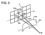
- Fig. 3 is a constitution diagram showing an evaluation model.
- Fig. 4 is a flowchart showing the process of calculation for obtaining a deviation of the position of a grid point seen through the transparent body.
- Fig. 5 is a diagram showing the process of calculation for obtaining a deviation of the position a grid point seen through the transparent body.
- Fig. 6 is a diagram showing an evaluation pattern formed freshly according to the evaluation model.
- Fig. 7 is a graph showing grid distance ratios in lateral directions.
- Fig. 8A is a graph showing a result of calculation of dynamic distortion values.
- Fig. 8B is a graph showing a result of measurement of the dynamic perspective distortion in a sensory evaluation test.
- Fig. 9 is a graph showing the relation between the dynamic distortion value of the transparent body and the intensity of the dynamic distortion.
- Fig. 1 is a flowchart showing the method of evaluation of the dynamic perspective distortion according to an embodiment of the present invention.
- Fig. 2 is a block diagram showing an evaluation system for carrying out the method for evaluating the dynamic perspective distortion shown in Fig. 1.
- Fig. 3 shows an evaluation model.
- a model of three-dimensionally curved shape of a transparent body is produced by reading out the data of shape by means of an input device, a memory device or the like (Step S1).
- the method for inputting the data of shape is well known, and CAD data 5 may be inputted into a computer 9 with a magnetic tape or the like by means of a magnetic reproducing device 6, or data obtained by plotting a designed drawing 7 with a digitizer 8 may be inputted into the computer 9, as shown in Fig. 2.
- a known technique can be used for producing the three-dimensionally curved shape of the transparent body. For example, three-dimensional coordinate data of a large number of points on a plan view and a side view, called a Mylar diagram, of the transparent body are inputted into the computer 9.
- a central processing unit 17 which has received input data, produces grid-like three-dimensional spline curves passing a train of points; divides a curved plane into rectangular patches defined by the spline curves as boundaries, and produces a dual third parametric curved plane like a Coons plane which is expressed by parameters along each side of patches. And, it renders the curved plane to be the shape model of an inner surface of a plate-like transparent body, and produces the shape model of an outer surface by offsetting the shape model of the inner surface by the thickness of the transparent body.
- the finally determined shape model is obtainable by combining the shape models of the inner and outer surfaces.
- the data of the obtained shape model are stored in a shape data file 18.
- the above-mentioned series of works for producing the model of three-dimensionally curved shape are carried out by the central processing unit 17 which reads out for execution a program stored as a shape model producing means 11 in a program section 10 of the computer 9.
- the central processing unit 17 determines an eye point EP (Step S2) and produces virtual grid board (Step S3) based on data in a condition data file 19 in which determination conditions previously inputted by a key-input means 4 are stored.
- a virtual grid board 2 (see Fig. 3) is assumed for a virtual evaluation pattern, and grid points (PS1, PS2 and PS3) are assumed as evaluation points.
- another evaluation pattern having regularly arranged points in lateral and vertical directions may be used. Evaluation points seen from the eye point EP become grid points (PR1, PR2 and PR3 (hereinbelow, referred to as perspective evaluation point)) due to the refraction index of the transparent body.
- the fitting angle of the shape model of the transparent body; the distances between the eye point EP and the shape model 1 of the transparent body and between the eye point and the virtual grid board 2, and the grid distance of the virtual grid board 2 are determined.
- all conditions before the initiation of the measurement are determined, and obtained arrangement data are stored in an arrangement data file 20 (Step S4).
- the computer 9 calls an optical path tracing/calculating means 13 in the program section 10 to define a virtual line with respect to the shape model 1 of the transparent body by using the arrangement data on the shape model 1 of the transparent body, the eye point EP and the virtual grid board 2 (Step S5), and to conduct calculation for obtaining a perspective distortion due to the refraction (a deviation of the position of a grid point observed from the eye point EP) (Step S6).
- the calculation of the deviation of the position of a grid point is, in principle, conducted by utilizing the fact that the propagating direction of a light beam is different due to the refraction effect depending on the presence or absence of the shape model 1 of the transparent body.
- Fig. 4 shows concretely the flow of the calculation. Further, the tracing of the optical path is explained in detail by using Fig. 5.
- an optional grid point P0 is determined on the virtual grid board 2 (Step SS1). Then, a vector VR0 in the propagating direction of a virtual light beam 3 directing from the eye point EP toward P0 is obtained (Step SS2). Then, the intersection point P1 between a linear line passing through the eye point EP and having the same direction as the vector VR0 and an inner surface SU1 of the shape model 1 of the transparent body is obtained (Step SS3), and a vector VE1 along the normal line of the inner surface of the shape model 1 of the transparent body at the intersection point P1 is obtained (Step SS4).
- a vector VR1 which indicates the propagating path after the virtual light beam 3 is refracted at the outer surface SU2 of the shape model 1 of the transparent body, is obtained (Step SS5).
- the incident angle (with respect to the normal line) of the virtual light beam 3 from the eye point EP to the inner surface SU1 is assumed i
- the refractive angle (with respect to the normal line) of the virtual light beam 3 at the inner surface SU1 is r and the refractive index of the transparent body to air is n
- the vector VR1 is obtainable based on these.
- Step SS6 the intersection point P2 between a linear line passing through the intersection point P1 and having the same direction as the vector VR1 and an outer surface SU2 of the shape model 1 of the transparent body is obtained (Step SS6), and a vector VE2 along the normal line on the outer surface SU2 of the shape model 1 of the transparent body at the intersection point P2 is obtained (Step SS7).
- Step SS8 a vector vR2 which indicates the propagating path after the virtual light beam 3 is refracted at the outer surface SU2 of the shape model 1 of the transparent body.
- Step SS9 the intersection point P3 between a linear line passing through the intersection point P2 and having the same direction as the vector VR2 and the virtual grid board 2 is obtained (Step SS9).
- P1 is moved by a distance shorter than a line segment P3P0 in the direction of a vector P3P0 to determine a fresh P1 (hereinbelow, referred to as P1 1 ), so that P3 is again obtained.
- P1 1 is replaced by P1, and VR2 is obtained.
- the position of the intersection point (virtual point) P1 can be in approximation the position where the virtual point P0 can actually be observed from the eye point EP.
- intersection points corresponding to respective grid points are obtainable by executing Steps SS1 to SS10 (Step S7). By connecting these intersection points, a fresh shape of the grids can be constructed (Step S8). The data of the intersection points are stored in a result data file 21.
- the dynamic distortion value as a parameter for evaluating the dynamic perspective distortion and the intensity of the dynamic distortion value are obtained.
- the program for obtaining each parameter is stored in a result data evaluation means 14 in the program section 10.
- the narrowest grid distance in a vertical direction among grid distances (between the intersection points) which are seen from the transparent body is calculated. For example, explanation is made assuming that perspective evaluation points PR1, PR2 and PR3 as intersection points corresponding to three grid points PS1, PS2 and PS3 in Fig. 3, have been obtained.
- the distance between the perspective evaluation points PR1 and PR2 is the grid distance in a vertical direction. The distance can be obtained from the coordinate values of two points. By obtaining all grid distances in the vertical direction as described, the minimum value among them can be found (Step S9).
- Fig. 6 shows an evaluation pattern formed freshly from the evaluation model wherein d1 to dn indicate grid distances in a vertical direction.
- the minimum value of the grid distance is indicated by d4.
- the maximum value of the grid distance ratios is determined to be a dynamic distortion value (Step S11).
- a dynamic distortion value is also obtained in a lateral direction in the same manner.
- a grid distance in a lateral direction is obtained.
- the distance between perspective evaluation points PR1 and PR3 is the grid distance in the lateral direction.
- the minimum value among them can be found.
- grid distance ratios can be obtained.
- the maximum value among them is determined to be a dynamic distortion value (Step S12).
- the minimum value of grid distances is determined to be the reference value and each grid distance ratio can be obtained by dividing each of the other grid distances in vertical and lateral directions by the reference value.
- the maximum value among them is defined as the dynamic distortion value.
- the dynamic distortion value is a relative value based on the ratio of the reference value which is an optional one among the grid distances, to the other grid distance. Accordingly, the dynamic distortion value may be determined irrespective of this embodiment.
- the reference value is determined as the minimum value of the grid distances and the maximum value is determined in the relation of the other grid distances to the minimum value
- the calculation in the determination of the minimum value can quickly and easily be performed. Further, the difference between an expansively visible portion and a diminutively visible portion due to the perspective distortion can easily be expressed numerically.
- the rate of change of the grid distance ratios in both the vertical and lateral directions is calculated (Step S13).
- the grid distance ratios are placed in the order from left to right in the direction of a linear line L1 which traverses laterally the virtual grid board 2 in Fig. 3.
- Fig. 7 is a graph showing such state which is obtainable by selecting a region wherein the gradient seems to be the largest, and applying a least squares method or a suitable method to the grid distance ratio of this region.
- the rate of change of the grid distance ratios is calculated as the gradient based on the graph, and the maximum value of the gradient is determined as the intensity of the dynamic distortion (Step S14).
- the computer calls a model shape determining means 15 in the program section 10.
- the obtained dynamic distortion value is compared with a previously determined threshold value (Step S15).
- a judgement of acceptance is made whereby the operation of judgement is finished.
- a judgement of rejection is made whereby the operation of shape adjustment is carried out on CAD (Step S16).
- the portion of the shape model which corresponds to a portion where the grid distance becomes maximal is displayed, and it is requested to change the surface curvature and the trim shape of that portion.
- the above-mentioned data processing is carried out to obtain the dynamic distortion value (Step S17). Simulation and adjustment are repeated until a value lower than the threshold value can be obtained.
- the optimum shape can be obtained.
- the computer 9 calls an animation producing means 16 in the program section 10.
- a scenery seen through the accepted shape model of the transparent body from, for example, a cruising automobile is displayed in the form of an animation image in a graphic display 24 in order to confirm visually that the adjustment has been completed.
- the animation display is conducted by utilizing the result data stored in the result data file 21.
- the operation for the shape model before the adjustment is also conducted similarly. Namely, a scenery seen through the transparent body from, for example, a cruising automobile is displayed in the form of an animation image such as CG (Computer Graphics) or the like, in the graphic display 24.
- CG Computer Graphics
- Shape models were prepared using a large number of actual transparent bodies, and the dynamic distortion values were calculated on the shape models respectively (Fig. 8A).
- sensory evaluation tests for 5-step evaluation were conducted to a plurality of tested persons to examine the feeling of flickering in a case that a moving object was actually seen through these transparent bodies (Fig. 8B).
- the abscissa indicates samples A to I and the ordinate indicates the dynamic distortion value.
- the dynamic distortion value has extremely high correlation to the evaluation by actual observation by eye, namely, the value was an index which sufficiently reflected the dynamic perspective distortion.
- the threshold value of the dynamic distortion value was determined to be 1.6.
- the present invention it is possible to quantify the dynamic perspective distortion (the dynamic distortion value and the intensity of the dynamic distortion) of a transparent body, which has not been used for the evaluation, and evaluation can be conducted with higher reliability than conventional technique to the dynamic perspective distortion which is caused when outward things are seen through a transparent body such as glass, resin or the like from a movable body such as an automobile.
- the feedback to the manufacturing process can be easily with the improvement of accuracy in designing; the yield percentage and the quality can be improved; cost for unnecessary manufacture of mold or modification of mold can be reduced to reduce cost, and the flexibility of designing can be expanded. Accordingly, the present invention is in particular effective for large item small scale production.
Landscapes
- Engineering & Computer Science (AREA)
- Physics & Mathematics (AREA)
- Theoretical Computer Science (AREA)
- General Physics & Mathematics (AREA)
- Geometry (AREA)
- Computer Graphics (AREA)
- Software Systems (AREA)
- Computing Systems (AREA)
- Computer Hardware Design (AREA)
- Evolutionary Computation (AREA)
- General Engineering & Computer Science (AREA)
- Length Measuring Devices By Optical Means (AREA)
- Processing Or Creating Images (AREA)
- Management, Administration, Business Operations System, And Electronic Commerce (AREA)
- Length Measuring Devices With Unspecified Measuring Means (AREA)
Abstract
Description
- 1A
- Shape data
- 1B
- Condition data file
·Attribution of transparent body
·Definition of measurement position - S1
- Producing shape model
- S2
- Determining eye point
- S3
- Producing virtual grid board
- S4
- Determining conditions of measurement
·Fitting angle of transparent body
·Distance between eye point and transparent body and between eye point and virtual grid board
·Grid distance of grid board - S5
- Defining visual line to transparent body
- S6
- Calculating position of grid point seen through transparent body by tracing refracted light
- S7
- Finishing calculation on all grid points
- S8
- Producing grid shape seen through transparent body
- S9
- Obtaining minimum value of grid distance in vertical direction
- S10
- obtaining grid distance ratio by dividing each grid distance by minimum value
- S11
- Determining maximum value of grid distance ratio to be dynamic distortion value
- S12
- Calculation in lateral direction
- 1C
- Shape data file
- 1D
- Arrangement data file
- 1E
- Result data file
- S13
- Calculating rate of change of grid distance ratio in vertical and lateral directions
- S14
- Determining rate of change of grid distance ratios to be dynamic distortion intensity
- S15
- Is dynamic distortion value 1.6 or less?
- S16
- Correcting shape of transparent body, surface curvature and trim, by CAD
- S17
- Re-calculating dynamic distortion value
- S18
- Confirming visually effect by animation
- 1F
- End
- 4
- Key-input means
- 5
- CAD data
- 6
- Magnetic reproducing device
- 7
- Designed drawing
- 8
- Digitizer
- 9
- Computer
- 10
- Program section
- 11
- Shape model producing means
- 12
- Evaluation condition determining means
- 13
- Optical path tracing/calculating means
- 14
- Result data evaluation means
- 15
- Model shape determining means
- 16
- Animation producing means
- 17
- Central processing unit
- 18
- Shape data file
- 19
- Condition data file
- 20
- Arrangement data file
- 21
- Result data file
- 22
- Result display means
- 23
- Printer
- 24
- Graphic display
- SS1
- Determining PO
- SS2
- Obtaining VR0 directing from EP toward PO
- SS3
- Obtaining an intersection point P1 at the intersection of VR0 to an inner surface SU1 of the shape model
- SS4
- Obtaining a normal line vector VE1 on the inner surface SU1 at P1
- SS5
- Obtaining a refraction vector VR1 from VR0 and VE1
- SS6
- Obtaining an intersection point P2 at the intersection of VR1 to an outer surface SU2 of the shape model
- SS7
- Obtaining a normal line vector VE2 on the outer surface SU2 at P2
- SS8
- Obtaining a refraction vector VR2 from VR1 and VE2
- SS9
- Obtaining an intersection point P3 at the intersection of the line passing through VR2 to a grid broad 2
- SS10
- Moving repeatedly P1 to find VR2 so as to approach P3≒P0, and repeating the above operation to find P1 so as to approach P3≒P0
Claims (12)
- A method for evaluating the dynamic perspective distortion of a transparent body, which comprises:a step of producing a model of three-dimensionally curved shape of a transparent body having a predetermined refractive index;a step of determining an eye point at a side of the model of three-dimensionally curved shape and a virtual evaluation pattern having a plurality of evaluation points at the other side of the model of three-dimensionally curved shape;a step of observing, from the eye point, the virtual evaluation pattern through the transparent body, extracting perspective evaluation points as images of the evaluation points, obtained by observing through the transparent body, in a two-dimensional picture image obtained by the observation, and obtaining distance values of adjacent perspective evaluation points;a step of determining an optional value to be a reference value, among these distance values, anda step of evaluating the dynamic perspective distortion of the transparent body by obtaining ratios of the distance values to the reference value.
- The method for evaluating the dynamic perspective distortion of a transparent body according to Claim 1, wherein the dynamic perspective distortion of the transparent body is evaluated based on the rate of change of the ratios of the distance values to the reference value.
- The method for evaluating the dynamic perspective distortion of a transparent body according to Claim 1 or 2, wherein the minimum value among the distance values is selected as the reference value, and the dynamic perspective distortion of the transparent body is evaluated based on the maximum value among the ratios of the distance values with respect to the minimum value.
- The method for evaluating the dynamic perspective distortion of a transparent body according to any one of Claims 1 to 3, wherein the virtual evaluation pattern is an orthogonal grid pattern.
- The method for evaluating the dynamic perspective distortion of a transparent body according to any one of Claims 1 to 4, wherein the transparent body is at least one selected from a glass sheet and a resinous plate.
- The method for evaluating the dynamic perspective distortion of a transparent body according to any one of Claims 1 to 5, wherein the image seen through the model of three-dimensionally curved shape of the transparent body is animation-displayed.
- A method for supporting the designing of the three-dimensionally curved shape of a transparent body, which comprises:a step of producing a model of three-dimensionally curved shape of a transparent body having a predetermined refractive index;a step of determining an eye point at a side of the model of three-dimensionally curved shape and a virtual evaluation pattern having a plurality of evaluation points at the other side of the model of three-dimensionally curved shape;a step of observing, from the eye point, the virtual evaluation pattern through the transparent body, extracting perspective evaluation points as images of the evaluation points, obtained by observing through the transparent body, in a two-dimensional picture image obtained by the observation, and obtaining distance values of adjacent perspective evaluation points;a step of determining an optional value to be a reference value, among these distance values;a step of evaluating the dynamic perspective distortion of the transparent body by obtaining ratios of the distance values to the reference value, anda step of correcting the three-dimensionally curved shape of the transparent body according to the evaluation.
- The method for supporting the designing of the three-dimensionally curved shape of a transparent body according to Claim 7, wherein the dynamic perspective distortion of the transparent body is evaluated based on the rate of change of the ratios of the distance values to the reference value.
- The method for supporting the designing of the three-dimensionally curved shape of a transparent body according to Claim 7 or 8, wherein the minimum value among the distance values is selected as the reference value, and the dynamic perspective distortion of the transparent body is evaluated based on the maximum value among the ratios of the distance values with respect to the minimum value.
- The method for supporting the designing of the three-dimensionally curved shape of a transparent body according to any one of Claims 7 to 9, wherein the virtual evaluation pattern is an orthogonal grid pattern.
- The method for supporting the designing of the three-dimensionally curved shape of a transparent body according to any one of Claims 7 to 10, wherein the transparent body is at least one selected from a glass sheet and a resinous plate.
- The method for supporting the designing of the three-dimensionally curved shape of a transparent body according to any one of Claims 7 to 11, wherein the image seen through the model of three-dimensionally curved shape of the transparent body is animation-displayed.
Applications Claiming Priority (3)
| Application Number | Priority Date | Filing Date | Title |
|---|---|---|---|
| JP2000193035 | 2000-06-27 | ||
| JP2000193035 | 2000-06-27 | ||
| PCT/JP2001/005469 WO2002001422A1 (en) | 2000-06-27 | 2001-06-26 | Method for evaluating dynamic perspective distortion of transparent body and method for supporting designing of three-dimensional shape of transparent body |
Publications (2)
| Publication Number | Publication Date |
|---|---|
| EP1315105A1 true EP1315105A1 (en) | 2003-05-28 |
| EP1315105A4 EP1315105A4 (en) | 2006-01-18 |
Family
ID=18692095
Family Applications (1)
| Application Number | Title | Priority Date | Filing Date |
|---|---|---|---|
| EP01941259A Withdrawn EP1315105A4 (en) | 2000-06-27 | 2001-06-26 | METHOD FOR EVALUATING A DYNAMIC PERSPECTIVE DISTORTION OF A TRANSPARENT BODY, AND METHOD FOR SUPPORTING THE DESIGN OF A THREE-DIMENSIONAL SHAPE OF THE TRANSPARENT BODY |
Country Status (10)
| Country | Link |
|---|---|
| US (1) | US7162398B2 (en) |
| EP (1) | EP1315105A4 (en) |
| JP (1) | JP4736304B2 (en) |
| KR (1) | KR100759743B1 (en) |
| CN (1) | CN1383518A (en) |
| AU (1) | AU7462601A (en) |
| BR (1) | BR0106898A (en) |
| CZ (1) | CZ2002489A3 (en) |
| MX (1) | MXPA02002070A (en) |
| WO (1) | WO2002001422A1 (en) |
Cited By (2)
| Publication number | Priority date | Publication date | Assignee | Title |
|---|---|---|---|---|
| FR3078161A1 (en) * | 2018-02-22 | 2019-08-23 | Saint-Gobain Glass France | METHOD FOR SIMULATING THE OPTICAL POWER OF A LAMINATED GLASS |
| US10509867B2 (en) | 2014-08-21 | 2019-12-17 | Nippon Steel Corporation | Structure design support device, structure design support method, program, and recording medium |
Families Citing this family (4)
| Publication number | Priority date | Publication date | Assignee | Title |
|---|---|---|---|---|
| CN102016853B (en) * | 2008-02-27 | 2013-03-13 | 矢崎总业株式会社 | Planar manufacturing drawing production support device, planar manufacturing drawing production support method, and branch angle design support device |
| US9933373B2 (en) * | 2014-04-29 | 2018-04-03 | Glasstech, Inc. | Glass sheet acquisition and positioning mechanism for an inline system for measuring the optical characteristics of a glass sheet |
| US9818021B2 (en) * | 2014-10-21 | 2017-11-14 | Isra Surface Vision Gmbh | Method for determining a local refractive power and device therefor |
| US10851013B2 (en) | 2015-03-05 | 2020-12-01 | Glasstech, Inc. | Glass sheet acquisition and positioning system and associated method for an inline system for measuring the optical characteristics of a glass sheet |
Family Cites Families (12)
| Publication number | Priority date | Publication date | Assignee | Title |
|---|---|---|---|---|
| US4310242A (en) * | 1980-04-01 | 1982-01-12 | The United States Of America As Represented By The Secretary Of The Air Force | Field test unit for windscreen optical evaluation |
| JPH0682090B2 (en) * | 1988-07-16 | 1994-10-19 | 日本板硝子株式会社 | Simulation method of transparent double image of flat glass |
| JP2560470B2 (en) * | 1989-02-27 | 1996-12-04 | 日本板硝子株式会社 | Evaluation method of perspective distortion of laminated glass plate |
| JPH0629705B2 (en) * | 1989-10-20 | 1994-04-20 | セントラル硝子株式会社 | Plate inspection method |
| CA2078115A1 (en) * | 1990-03-13 | 1991-09-14 | Heinz V. Wenz | Process and device for measuring the dimensions of a space, in particular a buccal cavity |
| JP3161787B2 (en) * | 1991-11-30 | 2001-04-25 | 株式会社ニデック | Lens refractive power distribution observation device |
| US5568258A (en) * | 1992-08-25 | 1996-10-22 | Asahi Glass Company Ltd. | Method and device for measuring distortion of a transmitting beam or a surface shape of a three-dimensional object |
| JP3302078B2 (en) * | 1993-02-16 | 2002-07-15 | 日本板硝子株式会社 | Inspection method of windshield of automobile |
| US5398539A (en) | 1993-08-02 | 1995-03-21 | Hewlett-Packard Company | Correlated multi-dimensional chromatography with confirmatory hybrid run |
| US5812260A (en) * | 1995-10-16 | 1998-09-22 | Corning Incorporated | Method and system for measuring optical distortion |
| JP3951362B2 (en) * | 1997-06-12 | 2007-08-01 | 株式会社セガ | Image processing apparatus, game apparatus, method thereof, and recording medium |
| US6208412B1 (en) * | 1999-06-14 | 2001-03-27 | Visteon Global Technologies, Inc. | Method and apparatus for determining optical quality |
-
2001
- 2001-06-26 MX MXPA02002070A patent/MXPA02002070A/en unknown
- 2001-06-26 CN CN01801822A patent/CN1383518A/en active Pending
- 2001-06-26 BR BR0106898-9A patent/BR0106898A/en not_active Application Discontinuation
- 2001-06-26 KR KR1020027002438A patent/KR100759743B1/en not_active Expired - Fee Related
- 2001-06-26 EP EP01941259A patent/EP1315105A4/en not_active Withdrawn
- 2001-06-26 CZ CZ2002489A patent/CZ2002489A3/en unknown
- 2001-06-26 JP JP2002506486A patent/JP4736304B2/en not_active Expired - Fee Related
- 2001-06-26 AU AU74626/01A patent/AU7462601A/en not_active Abandoned
- 2001-06-26 WO PCT/JP2001/005469 patent/WO2002001422A1/en not_active Ceased
-
2002
- 2002-02-22 US US10/079,586 patent/US7162398B2/en not_active Expired - Fee Related
Cited By (2)
| Publication number | Priority date | Publication date | Assignee | Title |
|---|---|---|---|---|
| US10509867B2 (en) | 2014-08-21 | 2019-12-17 | Nippon Steel Corporation | Structure design support device, structure design support method, program, and recording medium |
| FR3078161A1 (en) * | 2018-02-22 | 2019-08-23 | Saint-Gobain Glass France | METHOD FOR SIMULATING THE OPTICAL POWER OF A LAMINATED GLASS |
Also Published As
| Publication number | Publication date |
|---|---|
| JP4736304B2 (en) | 2011-07-27 |
| EP1315105A4 (en) | 2006-01-18 |
| CN1383518A (en) | 2002-12-04 |
| US7162398B2 (en) | 2007-01-09 |
| KR20020027581A (en) | 2002-04-13 |
| CZ2002489A3 (en) | 2002-07-17 |
| BR0106898A (en) | 2002-04-30 |
| US20020123868A1 (en) | 2002-09-05 |
| MXPA02002070A (en) | 2002-08-20 |
| AU7462601A (en) | 2002-01-08 |
| KR100759743B1 (en) | 2007-09-20 |
| WO2002001422A1 (en) | 2002-01-03 |
Similar Documents
| Publication | Publication Date | Title |
|---|---|---|
| US6785640B1 (en) | Surface evaluation in a stamping manufacturing process utilizing true reflection line methodology and computer graphics technology | |
| US6937235B2 (en) | Three-dimensional object surface shape modeling apparatus, method and program | |
| JP5666013B2 (en) | Method and system for determining surface defects in a model of an object | |
| US8089478B2 (en) | Model simplification apparatus and program | |
| US20100114350A1 (en) | Method of determining mesh data and method of correcting model data | |
| US11934743B2 (en) | Method for measuring the surface shape of a toric mirror | |
| US6862560B1 (en) | Machining simulation method and apparatus | |
| CN105550688A (en) | Method and device for point cloud data classification | |
| US7162398B2 (en) | Method for evaluating the dynamic perspective distortion of a transparent body and method for supporting the designing of a three-dimensionally curved shape of a transparent body | |
| JP2010211680A (en) | Method of correcting model data | |
| JPWO2002001422A1 (en) | Dynamic perspective distortion evaluation method for transparent objects and three-dimensional shape design support method for transparent objects | |
| US7218321B2 (en) | Hidden line processing method for erasing hidden lines in projecting a three-dimensional model consisting of a plurality of polygons onto a two-dimensional plane | |
| JP2000122996A (en) | Evaluation method of shape defect on work surface | |
| JPH0623992B2 (en) | Sheet glass inspection method | |
| JP3302078B2 (en) | Inspection method of windshield of automobile | |
| CN111712824B (en) | Method for modeling optical power of laminated glass | |
| JP2003132097A (en) | Apparatus and method for calculating deformed shape | |
| JPH0227232A (en) | Simulation of see-through double image for plate glass | |
| JP4032828B2 (en) | Graphic front / back setting device and graphic front / back setting method | |
| JP3900839B2 (en) | Graphic front / back setting device and graphic front / back setting method | |
| KR100219587B1 (en) | Block data structure and hidden face removal method for three-dimension computer graphics | |
| JPH06314317A (en) | Stereoscopic diagram drawing method for cad data | |
| JPH09146992A (en) | Method to generate 3D data from 2D drawing | |
| JP2002312406A (en) | System for inspecting window shield of automobile | |
| WO2022115928A1 (en) | Methods and systems for the quality inspection of three-dimensional materials and surfaces in a virtual environment |
Legal Events
| Date | Code | Title | Description |
|---|---|---|---|
| PUAI | Public reference made under article 153(3) epc to a published international application that has entered the european phase |
Free format text: ORIGINAL CODE: 0009012 |
|
| 17P | Request for examination filed |
Effective date: 20030123 |
|
| AK | Designated contracting states |
Designated state(s): AT BE CH CY DE DK ES FI FR GB GR IE IT LI LU MC NL PT SE TR |
|
| AX | Request for extension of the european patent |
Extension state: AL LT LV MK RO SI |
|
| RBV | Designated contracting states (corrected) |
Designated state(s): BE DE FR GB IT |
|
| A4 | Supplementary search report drawn up and despatched |
Effective date: 20051205 |
|
| 17Q | First examination report despatched |
Effective date: 20060904 |
|
| RAP1 | Party data changed (applicant data changed or rights of an application transferred) |
Owner name: ASAHI GLASS COMPANY, LIMITED |
|
| GRAP | Despatch of communication of intention to grant a patent |
Free format text: ORIGINAL CODE: EPIDOSNIGR1 |
|
| RIC1 | Information provided on ipc code assigned before grant |
Ipc: G06T 15/00 20110101AFI20131007BHEP |
|
| INTG | Intention to grant announced |
Effective date: 20131030 |
|
| STAA | Information on the status of an ep patent application or granted ep patent |
Free format text: STATUS: THE APPLICATION IS DEEMED TO BE WITHDRAWN |
|
| 18D | Application deemed to be withdrawn |
Effective date: 20140103 |