EP1315033A1 - Ionic liquids as coupler solvents in photothermographic systems - Google Patents
Ionic liquids as coupler solvents in photothermographic systems Download PDFInfo
- Publication number
- EP1315033A1 EP1315033A1 EP02079689A EP02079689A EP1315033A1 EP 1315033 A1 EP1315033 A1 EP 1315033A1 EP 02079689 A EP02079689 A EP 02079689A EP 02079689 A EP02079689 A EP 02079689A EP 1315033 A1 EP1315033 A1 EP 1315033A1
- Authority
- EP
- European Patent Office
- Prior art keywords
- silver
- group
- coupler
- compounds
- light
- Prior art date
- Legal status (The legal status is an assumption and is not a legal conclusion. Google has not performed a legal analysis and makes no representation as to the accuracy of the status listed.)
- Withdrawn
Links
- 239000002608 ionic liquid Substances 0.000 title claims abstract description 91
- 239000002904 solvent Substances 0.000 title abstract description 55
- -1 ester compounds Chemical class 0.000 claims description 142
- 229910052709 silver Inorganic materials 0.000 claims description 113
- 239000004332 silver Substances 0.000 claims description 113
- 239000000975 dye Substances 0.000 claims description 97
- 239000000839 emulsion Substances 0.000 claims description 76
- BQCADISMDOOEFD-UHFFFAOYSA-N Silver Chemical compound [Ag] BQCADISMDOOEFD-UHFFFAOYSA-N 0.000 claims description 66
- 125000000217 alkyl group Chemical group 0.000 claims description 43
- 238000000034 method Methods 0.000 claims description 42
- 239000003795 chemical substances by application Substances 0.000 claims description 39
- 239000000463 material Substances 0.000 claims description 34
- 238000003384 imaging method Methods 0.000 claims description 29
- 238000011161 development Methods 0.000 claims description 24
- 239000000203 mixture Substances 0.000 claims description 24
- 150000001450 anions Chemical group 0.000 claims description 23
- 230000002209 hydrophobic effect Effects 0.000 claims description 21
- 150000003839 salts Chemical class 0.000 claims description 19
- 125000004435 hydrogen atom Chemical group [H]* 0.000 claims description 17
- 230000035945 sensitivity Effects 0.000 claims description 15
- 239000003960 organic solvent Substances 0.000 claims description 8
- JUJWROOIHBZHMG-UHFFFAOYSA-N Pyridine Chemical class C1=CC=NC=C1 JUJWROOIHBZHMG-UHFFFAOYSA-N 0.000 claims description 5
- 125000005497 tetraalkylphosphonium group Chemical group 0.000 claims description 5
- NHNBFGGVMKEFGY-UHFFFAOYSA-N Nitrate Chemical compound [O-][N+]([O-])=O NHNBFGGVMKEFGY-UHFFFAOYSA-N 0.000 claims description 4
- WTKZEGDFNFYCGP-UHFFFAOYSA-N Pyrazole Chemical class C=1C=NNC=1 WTKZEGDFNFYCGP-UHFFFAOYSA-N 0.000 claims description 4
- 239000011230 binding agent Substances 0.000 claims description 4
- 229910002651 NO3 Inorganic materials 0.000 claims description 3
- 239000003086 colorant Substances 0.000 claims description 3
- VLTRZXGMWDSKGL-UHFFFAOYSA-M perchlorate Inorganic materials [O-]Cl(=O)(=O)=O VLTRZXGMWDSKGL-UHFFFAOYSA-M 0.000 claims description 3
- VLTRZXGMWDSKGL-UHFFFAOYSA-N perchloric acid Chemical compound OCl(=O)(=O)=O VLTRZXGMWDSKGL-UHFFFAOYSA-N 0.000 claims description 3
- QZHXKQKKEBXYRG-UHFFFAOYSA-N 4-n-(4-aminophenyl)benzene-1,4-diamine Chemical compound C1=CC(N)=CC=C1NC1=CC=C(N)C=C1 QZHXKQKKEBXYRG-UHFFFAOYSA-N 0.000 claims description 2
- 239000001013 indophenol dye Substances 0.000 claims description 2
- 239000012074 organic phase Substances 0.000 claims 6
- CZPWVGJYEJSRLH-UHFFFAOYSA-N Pyrimidine Chemical class C1=CN=CN=C1 CZPWVGJYEJSRLH-UHFFFAOYSA-N 0.000 claims 3
- 150000004693 imidazolium salts Chemical class 0.000 claims 3
- 125000005207 tetraalkylammonium group Chemical group 0.000 claims 3
- 239000010410 layer Substances 0.000 description 109
- GGCZERPQGJTIQP-UHFFFAOYSA-N sodium;9,10-dioxoanthracene-2-sulfonic acid Chemical compound [Na+].C1=CC=C2C(=O)C3=CC(S(=O)(=O)O)=CC=C3C(=O)C2=C1 GGCZERPQGJTIQP-UHFFFAOYSA-N 0.000 description 38
- 238000012545 processing Methods 0.000 description 37
- 125000004432 carbon atom Chemical group C* 0.000 description 36
- 150000001875 compounds Chemical class 0.000 description 34
- 239000006185 dispersion Substances 0.000 description 32
- 125000001424 substituent group Chemical group 0.000 description 31
- 238000011160 research Methods 0.000 description 27
- 239000000243 solution Substances 0.000 description 26
- 230000009102 absorption Effects 0.000 description 25
- 238000010521 absorption reaction Methods 0.000 description 25
- XLYOFNOQVPJJNP-UHFFFAOYSA-N water Substances O XLYOFNOQVPJJNP-UHFFFAOYSA-N 0.000 description 23
- 108010010803 Gelatin Proteins 0.000 description 22
- 239000008273 gelatin Substances 0.000 description 22
- 229920000159 gelatin Polymers 0.000 description 22
- 235000019322 gelatine Nutrition 0.000 description 22
- 235000011852 gelatine desserts Nutrition 0.000 description 22
- 238000000576 coating method Methods 0.000 description 19
- 230000008569 process Effects 0.000 description 19
- 239000000126 substance Substances 0.000 description 18
- 125000003118 aryl group Chemical group 0.000 description 17
- 238000006243 chemical reaction Methods 0.000 description 17
- 230000003595 spectral effect Effects 0.000 description 16
- 238000010438 heat treatment Methods 0.000 description 14
- 229910052770 Uranium Inorganic materials 0.000 description 13
- 239000011229 interlayer Substances 0.000 description 13
- 239000012071 phase Substances 0.000 description 13
- HEMHJVSKTPXQMS-UHFFFAOYSA-M Sodium hydroxide Chemical compound [OH-].[Na+] HEMHJVSKTPXQMS-UHFFFAOYSA-M 0.000 description 12
- 229910052736 halogen Inorganic materials 0.000 description 12
- 150000002367 halogens Chemical class 0.000 description 12
- 125000003545 alkoxy group Chemical group 0.000 description 11
- 239000011248 coating agent Substances 0.000 description 11
- 239000002736 nonionic surfactant Substances 0.000 description 11
- 230000005855 radiation Effects 0.000 description 11
- 239000004094 surface-active agent Substances 0.000 description 11
- 230000015572 biosynthetic process Effects 0.000 description 10
- 239000000084 colloidal system Substances 0.000 description 10
- 230000001965 increasing effect Effects 0.000 description 10
- YMWUJEATGCHHMB-UHFFFAOYSA-N Dichloromethane Chemical compound ClCCl YMWUJEATGCHHMB-UHFFFAOYSA-N 0.000 description 9
- 206010070834 Sensitisation Diseases 0.000 description 9
- 239000007788 liquid Substances 0.000 description 9
- 238000002156 mixing Methods 0.000 description 9
- 125000001997 phenyl group Chemical group [H]C1=C([H])C([H])=C(*)C([H])=C1[H] 0.000 description 9
- 230000008313 sensitization Effects 0.000 description 9
- 150000003378 silver Chemical class 0.000 description 9
- 230000006641 stabilisation Effects 0.000 description 9
- 238000011105 stabilization Methods 0.000 description 9
- IJGRMHOSHXDMSA-UHFFFAOYSA-N Atomic nitrogen Chemical compound N#N IJGRMHOSHXDMSA-UHFFFAOYSA-N 0.000 description 8
- 238000007792 addition Methods 0.000 description 8
- 239000007844 bleaching agent Substances 0.000 description 8
- 125000003917 carbamoyl group Chemical group [H]N([H])C(*)=O 0.000 description 8
- 230000000873 masking effect Effects 0.000 description 8
- 238000007639 printing Methods 0.000 description 8
- SQGYOTSLMSWVJD-UHFFFAOYSA-N silver(1+) nitrate Chemical compound [Ag+].[O-]N(=O)=O SQGYOTSLMSWVJD-UHFFFAOYSA-N 0.000 description 8
- 229910052717 sulfur Inorganic materials 0.000 description 8
- 230000000153 supplemental effect Effects 0.000 description 8
- 230000000903 blocking effect Effects 0.000 description 7
- 229910052799 carbon Inorganic materials 0.000 description 7
- 150000001768 cations Chemical class 0.000 description 7
- 238000010276 construction Methods 0.000 description 7
- 229910052739 hydrogen Inorganic materials 0.000 description 7
- 239000001257 hydrogen Substances 0.000 description 7
- 239000003921 oil Substances 0.000 description 7
- 230000003287 optical effect Effects 0.000 description 7
- 238000002360 preparation method Methods 0.000 description 7
- 230000004044 response Effects 0.000 description 7
- 239000002841 Lewis acid Substances 0.000 description 6
- NINIDFKCEFEMDL-UHFFFAOYSA-N Sulfur Chemical compound [S] NINIDFKCEFEMDL-UHFFFAOYSA-N 0.000 description 6
- 125000002252 acyl group Chemical group 0.000 description 6
- VSCWAEJMTAWNJL-UHFFFAOYSA-K aluminium trichloride Chemical compound Cl[Al](Cl)Cl VSCWAEJMTAWNJL-UHFFFAOYSA-K 0.000 description 6
- 239000003945 anionic surfactant Substances 0.000 description 6
- 125000004104 aryloxy group Chemical group 0.000 description 6
- 238000009835 boiling Methods 0.000 description 6
- 230000006870 function Effects 0.000 description 6
- 125000005843 halogen group Chemical group 0.000 description 6
- 125000000623 heterocyclic group Chemical group 0.000 description 6
- RAXXELZNTBOGNW-UHFFFAOYSA-N imidazole Natural products C1=CNC=N1 RAXXELZNTBOGNW-UHFFFAOYSA-N 0.000 description 6
- 239000002245 particle Substances 0.000 description 6
- WKEDVNSFRWHDNR-UHFFFAOYSA-N salicylanilide Chemical compound OC1=CC=CC=C1C(=O)NC1=CC=CC=C1 WKEDVNSFRWHDNR-UHFFFAOYSA-N 0.000 description 6
- 239000007787 solid Substances 0.000 description 6
- 238000001228 spectrum Methods 0.000 description 6
- 239000011593 sulfur Substances 0.000 description 6
- OKTJSMMVPCPJKN-UHFFFAOYSA-N Carbon Chemical compound [C] OKTJSMMVPCPJKN-UHFFFAOYSA-N 0.000 description 5
- 125000004423 acyloxy group Chemical group 0.000 description 5
- 125000004414 alkyl thio group Chemical group 0.000 description 5
- 238000005859 coupling reaction Methods 0.000 description 5
- 238000002844 melting Methods 0.000 description 5
- 229910052757 nitrogen Inorganic materials 0.000 description 5
- 229920000642 polymer Polymers 0.000 description 5
- 229950000975 salicylanilide Drugs 0.000 description 5
- 239000003381 stabilizer Substances 0.000 description 5
- 239000001043 yellow dye Substances 0.000 description 5
- CPELXLSAUQHCOX-UHFFFAOYSA-M Bromide Chemical compound [Br-] CPELXLSAUQHCOX-UHFFFAOYSA-M 0.000 description 4
- VEXZGXHMUGYJMC-UHFFFAOYSA-M Chloride anion Chemical compound [Cl-] VEXZGXHMUGYJMC-UHFFFAOYSA-M 0.000 description 4
- 108010002350 Interleukin-2 Proteins 0.000 description 4
- XEEYBQQBJWHFJM-UHFFFAOYSA-N Iron Chemical compound [Fe] XEEYBQQBJWHFJM-UHFFFAOYSA-N 0.000 description 4
- 241001637516 Polygonia c-album Species 0.000 description 4
- 239000002253 acid Substances 0.000 description 4
- 125000004453 alkoxycarbonyl group Chemical group 0.000 description 4
- 150000001412 amines Chemical class 0.000 description 4
- 125000004397 aminosulfonyl group Chemical group NS(=O)(=O)* 0.000 description 4
- 125000005110 aryl thio group Chemical group 0.000 description 4
- QVGXLLKOCUKJST-UHFFFAOYSA-N atomic oxygen Chemical compound [O] QVGXLLKOCUKJST-UHFFFAOYSA-N 0.000 description 4
- 239000012964 benzotriazole Substances 0.000 description 4
- 229910052801 chlorine Inorganic materials 0.000 description 4
- 125000001309 chloro group Chemical group Cl* 0.000 description 4
- 238000012937 correction Methods 0.000 description 4
- 125000004093 cyano group Chemical group *C#N 0.000 description 4
- PXBRQCKWGAHEHS-UHFFFAOYSA-N dichlorodifluoromethane Chemical compound FC(F)(Cl)Cl PXBRQCKWGAHEHS-UHFFFAOYSA-N 0.000 description 4
- 239000012153 distilled water Substances 0.000 description 4
- 230000000694 effects Effects 0.000 description 4
- 238000001704 evaporation Methods 0.000 description 4
- 230000008020 evaporation Effects 0.000 description 4
- 125000001165 hydrophobic group Chemical group 0.000 description 4
- 230000003993 interaction Effects 0.000 description 4
- 150000007517 lewis acids Chemical class 0.000 description 4
- 230000008018 melting Effects 0.000 description 4
- 125000002496 methyl group Chemical group [H]C([H])([H])* 0.000 description 4
- 239000003607 modifier Substances 0.000 description 4
- 230000007935 neutral effect Effects 0.000 description 4
- 150000002892 organic cations Chemical class 0.000 description 4
- 229910052760 oxygen Inorganic materials 0.000 description 4
- 239000001301 oxygen Substances 0.000 description 4
- JEXVQSWXXUJEMA-UHFFFAOYSA-N pyrazol-3-one Chemical class O=C1C=CN=N1 JEXVQSWXXUJEMA-UHFFFAOYSA-N 0.000 description 4
- GZTPJDLYPMPRDF-UHFFFAOYSA-N pyrrolo[3,2-c]pyrazole Chemical class N1=NC2=CC=NC2=C1 GZTPJDLYPMPRDF-UHFFFAOYSA-N 0.000 description 4
- 238000000926 separation method Methods 0.000 description 4
- 229910001961 silver nitrate Inorganic materials 0.000 description 4
- 238000011282 treatment Methods 0.000 description 4
- GGZHVNZHFYCSEV-UHFFFAOYSA-N 1-Phenyl-5-mercaptotetrazole Chemical class SC1=NN=NN1C1=CC=CC=C1 GGZHVNZHFYCSEV-UHFFFAOYSA-N 0.000 description 3
- ZWEHNKRNPOVVGH-UHFFFAOYSA-N 2-Butanone Chemical compound CCC(C)=O ZWEHNKRNPOVVGH-UHFFFAOYSA-N 0.000 description 3
- 241001479434 Agfa Species 0.000 description 3
- XEKOWRVHYACXOJ-UHFFFAOYSA-N Ethyl acetate Chemical compound CCOC(C)=O XEKOWRVHYACXOJ-UHFFFAOYSA-N 0.000 description 3
- OKKJLVBELUTLKV-UHFFFAOYSA-N Methanol Chemical compound OC OKKJLVBELUTLKV-UHFFFAOYSA-N 0.000 description 3
- 229910019142 PO4 Inorganic materials 0.000 description 3
- ISWSIDIOOBJBQZ-UHFFFAOYSA-N Phenol Chemical compound OC1=CC=CC=C1 ISWSIDIOOBJBQZ-UHFFFAOYSA-N 0.000 description 3
- FOIXSVOLVBLSDH-UHFFFAOYSA-N Silver ion Chemical compound [Ag+] FOIXSVOLVBLSDH-UHFFFAOYSA-N 0.000 description 3
- YSMRWXYRXBRSND-UHFFFAOYSA-N TOTP Chemical compound CC1=CC=CC=C1OP(=O)(OC=1C(=CC=CC=1)C)OC1=CC=CC=C1C YSMRWXYRXBRSND-UHFFFAOYSA-N 0.000 description 3
- 239000011358 absorbing material Substances 0.000 description 3
- 125000004442 acylamino group Chemical group 0.000 description 3
- 150000007933 aliphatic carboxylic acids Chemical class 0.000 description 3
- 239000008346 aqueous phase Substances 0.000 description 3
- 239000007864 aqueous solution Substances 0.000 description 3
- 230000008901 benefit Effects 0.000 description 3
- QRUDEWIWKLJBPS-UHFFFAOYSA-N benzotriazole Chemical compound C1=CC=C2N[N][N]C2=C1 QRUDEWIWKLJBPS-UHFFFAOYSA-N 0.000 description 3
- 125000003178 carboxy group Chemical group [H]OC(*)=O 0.000 description 3
- 239000003054 catalyst Substances 0.000 description 3
- 239000003638 chemical reducing agent Substances 0.000 description 3
- 239000000460 chlorine Substances 0.000 description 3
- 238000001816 cooling Methods 0.000 description 3
- 230000008878 coupling Effects 0.000 description 3
- 238000010168 coupling process Methods 0.000 description 3
- 238000000326 densiometry Methods 0.000 description 3
- 238000013461 design Methods 0.000 description 3
- 238000009792 diffusion process Methods 0.000 description 3
- 238000004090 dissolution Methods 0.000 description 3
- 239000002019 doping agent Substances 0.000 description 3
- LNTHITQWFMADLM-UHFFFAOYSA-N gallic acid Chemical compound OC(=O)C1=CC(O)=C(O)C(O)=C1 LNTHITQWFMADLM-UHFFFAOYSA-N 0.000 description 3
- 125000002887 hydroxy group Chemical group [H]O* 0.000 description 3
- 238000010348 incorporation Methods 0.000 description 3
- 239000003112 inhibitor Substances 0.000 description 3
- 239000000155 melt Substances 0.000 description 3
- 125000004433 nitrogen atom Chemical group N* 0.000 description 3
- 150000002894 organic compounds Chemical class 0.000 description 3
- 229920000139 polyethylene terephthalate Polymers 0.000 description 3
- 239000005020 polyethylene terephthalate Substances 0.000 description 3
- 239000002243 precursor Substances 0.000 description 3
- 230000009257 reactivity Effects 0.000 description 3
- 230000002829 reductive effect Effects 0.000 description 3
- 238000002310 reflectometry Methods 0.000 description 3
- 238000009877 rendering Methods 0.000 description 3
- 230000000717 retained effect Effects 0.000 description 3
- 230000001235 sensitizing effect Effects 0.000 description 3
- 238000001179 sorption measurement Methods 0.000 description 3
- 239000002344 surface layer Substances 0.000 description 3
- 125000002023 trifluoromethyl group Chemical group FC(F)(F)* 0.000 description 3
- 229920002554 vinyl polymer Polymers 0.000 description 3
- ZRHUHDUEXWHZMA-UHFFFAOYSA-N 1,4-dihydropyrazol-5-one Chemical compound O=C1CC=NN1 ZRHUHDUEXWHZMA-UHFFFAOYSA-N 0.000 description 2
- CBCKQZAAMUWICA-UHFFFAOYSA-N 1,4-phenylenediamine Chemical compound NC1=CC=C(N)C=C1 CBCKQZAAMUWICA-UHFFFAOYSA-N 0.000 description 2
- NJMWOUFKYKNWDW-UHFFFAOYSA-N 1-ethyl-3-methylimidazolium Chemical compound CCN1C=C[N+](C)=C1 NJMWOUFKYKNWDW-UHFFFAOYSA-N 0.000 description 2
- MCTWTZJPVLRJOU-UHFFFAOYSA-N 1-methyl-1H-imidazole Chemical compound CN1C=CN=C1 MCTWTZJPVLRJOU-UHFFFAOYSA-N 0.000 description 2
- KJUGUADJHNHALS-UHFFFAOYSA-N 1H-tetrazole Chemical compound C=1N=NNN=1 KJUGUADJHNHALS-UHFFFAOYSA-N 0.000 description 2
- AFBBKYQYNPNMAT-UHFFFAOYSA-N 1h-1,2,4-triazol-1-ium-3-thiolate Chemical compound SC=1N=CNN=1 AFBBKYQYNPNMAT-UHFFFAOYSA-N 0.000 description 2
- 125000004182 2-chlorophenyl group Chemical group [H]C1=C([H])C(Cl)=C(*)C([H])=C1[H] 0.000 description 2
- XRZDIHADHZSFBB-UHFFFAOYSA-N 3-oxo-n,3-diphenylpropanamide Chemical class C=1C=CC=CC=1NC(=O)CC(=O)C1=CC=CC=C1 XRZDIHADHZSFBB-UHFFFAOYSA-N 0.000 description 2
- HRPVXLWXLXDGHG-UHFFFAOYSA-N Acrylamide Chemical group NC(=O)C=C HRPVXLWXLXDGHG-UHFFFAOYSA-N 0.000 description 2
- KLSJWNVTNUYHDU-UHFFFAOYSA-N Amitrole Chemical group NC1=NC=NN1 KLSJWNVTNUYHDU-UHFFFAOYSA-N 0.000 description 2
- CIWBSHSKHKDKBQ-JLAZNSOCSA-N Ascorbic acid Chemical compound OC[C@H](O)[C@H]1OC(=O)C(O)=C1O CIWBSHSKHKDKBQ-JLAZNSOCSA-N 0.000 description 2
- ZAMOUSCENKQFHK-UHFFFAOYSA-N Chlorine atom Chemical compound [Cl] ZAMOUSCENKQFHK-UHFFFAOYSA-N 0.000 description 2
- 235000008733 Citrus aurantifolia Nutrition 0.000 description 2
- IAYPIBMASNFSPL-UHFFFAOYSA-N Ethylene oxide Chemical group C1CO1 IAYPIBMASNFSPL-UHFFFAOYSA-N 0.000 description 2
- RAXXELZNTBOGNW-UHFFFAOYSA-O Imidazolium Chemical compound C1=C[NH+]=CN1 RAXXELZNTBOGNW-UHFFFAOYSA-O 0.000 description 2
- GRYLNZFGIOXLOG-UHFFFAOYSA-N Nitric acid Chemical compound O[N+]([O-])=O GRYLNZFGIOXLOG-UHFFFAOYSA-N 0.000 description 2
- KDLHZDBZIXYQEI-UHFFFAOYSA-N Palladium Chemical compound [Pd] KDLHZDBZIXYQEI-UHFFFAOYSA-N 0.000 description 2
- 241001061127 Thione Species 0.000 description 2
- 235000011941 Tilia x europaea Nutrition 0.000 description 2
- SJOOOZPMQAWAOP-UHFFFAOYSA-N [Ag].BrCl Chemical compound [Ag].BrCl SJOOOZPMQAWAOP-UHFFFAOYSA-N 0.000 description 2
- 230000001594 aberrant effect Effects 0.000 description 2
- 230000001133 acceleration Effects 0.000 description 2
- 125000002777 acetyl group Chemical group [H]C([H])([H])C(*)=O 0.000 description 2
- 230000002378 acidificating effect Effects 0.000 description 2
- 125000004390 alkyl sulfonyl group Chemical group 0.000 description 2
- 229940051880 analgesics and antipyretics pyrazolones Drugs 0.000 description 2
- 125000003710 aryl alkyl group Chemical group 0.000 description 2
- 125000005161 aryl oxy carbonyl group Chemical group 0.000 description 2
- 125000004391 aryl sulfonyl group Chemical group 0.000 description 2
- WPYMKLBDIGXBTP-UHFFFAOYSA-N benzoic acid Chemical compound OC(=O)C1=CC=CC=C1 WPYMKLBDIGXBTP-UHFFFAOYSA-N 0.000 description 2
- 238000004061 bleaching Methods 0.000 description 2
- 210000000988 bone and bone Anatomy 0.000 description 2
- 125000001951 carbamoylamino group Chemical group C(N)(=O)N* 0.000 description 2
- 150000001721 carbon Chemical group 0.000 description 2
- YCIMNLLNPGFGHC-UHFFFAOYSA-N catechol Chemical compound OC1=CC=CC=C1O YCIMNLLNPGFGHC-UHFFFAOYSA-N 0.000 description 2
- 150000001767 cationic compounds Chemical class 0.000 description 2
- 229920002678 cellulose Polymers 0.000 description 2
- 238000001311 chemical methods and process Methods 0.000 description 2
- 230000001427 coherent effect Effects 0.000 description 2
- 238000011109 contamination Methods 0.000 description 2
- 238000007796 conventional method Methods 0.000 description 2
- DOIRQSBPFJWKBE-UHFFFAOYSA-N dibutyl phthalate Chemical compound CCCCOC(=O)C1=CC=CC=C1C(=O)OCCCC DOIRQSBPFJWKBE-UHFFFAOYSA-N 0.000 description 2
- 230000008030 elimination Effects 0.000 description 2
- 238000003379 elimination reaction Methods 0.000 description 2
- 230000002708 enhancing effect Effects 0.000 description 2
- 239000010419 fine particle Substances 0.000 description 2
- 239000011521 glass Substances 0.000 description 2
- 150000004820 halides Chemical class 0.000 description 2
- 125000005842 heteroatom Chemical group 0.000 description 2
- XMBWDFGMSWQBCA-UHFFFAOYSA-N hydrogen iodide Chemical compound I XMBWDFGMSWQBCA-UHFFFAOYSA-N 0.000 description 2
- 238000005286 illumination Methods 0.000 description 2
- PTFYQSWHBLOXRZ-UHFFFAOYSA-N imidazo[4,5-e]indazole Chemical class C1=CC2=NC=NC2=C2C=NN=C21 PTFYQSWHBLOXRZ-UHFFFAOYSA-N 0.000 description 2
- 125000002883 imidazolyl group Chemical group 0.000 description 2
- 230000006872 improvement Effects 0.000 description 2
- 230000002401 inhibitory effect Effects 0.000 description 2
- 229910001411 inorganic cation Inorganic materials 0.000 description 2
- 238000005342 ion exchange Methods 0.000 description 2
- 229910052742 iron Inorganic materials 0.000 description 2
- 238000003475 lamination Methods 0.000 description 2
- 239000004571 lime Substances 0.000 description 2
- 125000005647 linker group Chemical group 0.000 description 2
- 239000000314 lubricant Substances 0.000 description 2
- 238000004519 manufacturing process Methods 0.000 description 2
- 238000005259 measurement Methods 0.000 description 2
- 230000007246 mechanism Effects 0.000 description 2
- 125000004170 methylsulfonyl group Chemical group [H]C([H])([H])S(*)(=O)=O 0.000 description 2
- UHOVQNZJYSORNB-UHFFFAOYSA-N monobenzene Natural products C1=CC=CC=C1 UHOVQNZJYSORNB-UHFFFAOYSA-N 0.000 description 2
- AJDUTMFFZHIJEM-UHFFFAOYSA-N n-(9,10-dioxoanthracen-1-yl)-4-[4-[[4-[4-[(9,10-dioxoanthracen-1-yl)carbamoyl]phenyl]phenyl]diazenyl]phenyl]benzamide Chemical compound O=C1C2=CC=CC=C2C(=O)C2=C1C=CC=C2NC(=O)C(C=C1)=CC=C1C(C=C1)=CC=C1N=NC(C=C1)=CC=C1C(C=C1)=CC=C1C(=O)NC1=CC=CC2=C1C(=O)C1=CC=CC=C1C2=O AJDUTMFFZHIJEM-UHFFFAOYSA-N 0.000 description 2
- 150000004780 naphthols Chemical class 0.000 description 2
- 229910017604 nitric acid Inorganic materials 0.000 description 2
- 125000000449 nitro group Chemical group [O-][N+](*)=O 0.000 description 2
- QJGQUHMNIGDVPM-UHFFFAOYSA-N nitrogen group Chemical group [N] QJGQUHMNIGDVPM-UHFFFAOYSA-N 0.000 description 2
- 238000010534 nucleophilic substitution reaction Methods 0.000 description 2
- 239000007800 oxidant agent Substances 0.000 description 2
- 150000002989 phenols Chemical class 0.000 description 2
- NBIIXXVUZAFLBC-UHFFFAOYSA-K phosphate Chemical compound [O-]P([O-])([O-])=O NBIIXXVUZAFLBC-UHFFFAOYSA-K 0.000 description 2
- 239000010452 phosphate Substances 0.000 description 2
- 239000004014 plasticizer Substances 0.000 description 2
- BASFCYQUMIYNBI-UHFFFAOYSA-N platinum Chemical compound [Pt] BASFCYQUMIYNBI-UHFFFAOYSA-N 0.000 description 2
- 229920001983 poloxamer Polymers 0.000 description 2
- 238000001556 precipitation Methods 0.000 description 2
- 108090000623 proteins and genes Proteins 0.000 description 2
- 102000004169 proteins and genes Human genes 0.000 description 2
- GHMLBKRAJCXXBS-UHFFFAOYSA-N resorcinol Chemical compound OC1=CC=CC(O)=C1 GHMLBKRAJCXXBS-UHFFFAOYSA-N 0.000 description 2
- 238000012552 review Methods 0.000 description 2
- 125000006413 ring segment Chemical group 0.000 description 2
- 229920006395 saturated elastomer Polymers 0.000 description 2
- ADZWSOLPGZMUMY-UHFFFAOYSA-M silver bromide Chemical compound [Ag]Br ADZWSOLPGZMUMY-UHFFFAOYSA-M 0.000 description 2
- 239000002002 slurry Substances 0.000 description 2
- 230000003381 solubilizing effect Effects 0.000 description 2
- 238000006467 substitution reaction Methods 0.000 description 2
- KZNICNPSHKQLFF-UHFFFAOYSA-N succinimide Chemical compound O=C1CCC(=O)N1 KZNICNPSHKQLFF-UHFFFAOYSA-N 0.000 description 2
- 125000005420 sulfonamido group Chemical group S(=O)(=O)(N*)* 0.000 description 2
- 125000000472 sulfonyl group Chemical group *S(*)(=O)=O 0.000 description 2
- 125000004434 sulfur atom Chemical group 0.000 description 2
- 150000003573 thiols Chemical class 0.000 description 2
- 238000000108 ultra-filtration Methods 0.000 description 2
- 238000001429 visible spectrum Methods 0.000 description 2
- 238000004804 winding Methods 0.000 description 2
- JYEUMXHLPRZUAT-UHFFFAOYSA-N 1,2,3-triazine Chemical compound C1=CN=NN=C1 JYEUMXHLPRZUAT-UHFFFAOYSA-N 0.000 description 1
- YHMYGUUIMTVXNW-UHFFFAOYSA-N 1,3-dihydrobenzimidazole-2-thione Chemical compound C1=CC=C2NC(S)=NC2=C1 YHMYGUUIMTVXNW-UHFFFAOYSA-N 0.000 description 1
- WGJCBBASTRWVJL-UHFFFAOYSA-N 1,3-thiazolidine-2-thione Chemical compound SC1=NCCS1 WGJCBBASTRWVJL-UHFFFAOYSA-N 0.000 description 1
- IJHIIHORMWQZRQ-UHFFFAOYSA-N 1-(ethenylsulfonylmethylsulfonyl)ethene Chemical compound C=CS(=O)(=O)CS(=O)(=O)C=C IJHIIHORMWQZRQ-UHFFFAOYSA-N 0.000 description 1
- VXNZUUAINFGPBY-UHFFFAOYSA-N 1-Butene Chemical compound CCC=C VXNZUUAINFGPBY-UHFFFAOYSA-N 0.000 description 1
- FHDQNOXQSTVAIC-UHFFFAOYSA-M 1-butyl-3-methylimidazol-3-ium;chloride Chemical compound [Cl-].CCCCN1C=C[N+](C)=C1 FHDQNOXQSTVAIC-UHFFFAOYSA-M 0.000 description 1
- IQQRAVYLUAZUGX-UHFFFAOYSA-N 1-butyl-3-methylimidazolium Chemical compound CCCCN1C=C[N+](C)=C1 IQQRAVYLUAZUGX-UHFFFAOYSA-N 0.000 description 1
- REACWASHYHDPSQ-UHFFFAOYSA-N 1-butylpyridin-1-ium Chemical class CCCC[N+]1=CC=CC=C1 REACWASHYHDPSQ-UHFFFAOYSA-N 0.000 description 1
- VFWCMGCRMGJXDK-UHFFFAOYSA-N 1-chlorobutane Chemical compound CCCCCl VFWCMGCRMGJXDK-UHFFFAOYSA-N 0.000 description 1
- IAJJJYDLHJCUNY-KHPPLWFESA-N 1-methyl-3-[(z)-octadec-9-enyl]imidazol-1-ium Chemical class CCCCCCCC\C=C/CCCCCCCCN1C=C[N+](C)=C1 IAJJJYDLHJCUNY-KHPPLWFESA-N 0.000 description 1
- WSQVLVLHLJXOQP-GMFCBQQYSA-N 1-methyl-3-[(z)-octadec-9-enyl]imidazol-1-ium;tetrafluoroborate Chemical compound F[B-](F)(F)F.CCCCCCCC\C=C/CCCCCCCCN1C=C[N+](C)=C1 WSQVLVLHLJXOQP-GMFCBQQYSA-N 0.000 description 1
- JAAIPIWKKXCNOC-UHFFFAOYSA-N 1h-tetrazol-1-ium-5-thiolate Chemical compound SC1=NN=NN1 JAAIPIWKKXCNOC-UHFFFAOYSA-N 0.000 description 1
- HAZJTCQWIDBCCE-UHFFFAOYSA-N 1h-triazine-6-thione Chemical compound SC1=CC=NN=N1 HAZJTCQWIDBCCE-UHFFFAOYSA-N 0.000 description 1
- YQTCQNIPQMJNTI-UHFFFAOYSA-N 2,2-dimethylpropan-1-one Chemical group CC(C)(C)[C]=O YQTCQNIPQMJNTI-UHFFFAOYSA-N 0.000 description 1
- WMVJWKURWRGJCI-UHFFFAOYSA-N 2,4-bis(2-methylbutan-2-yl)phenol Chemical compound CCC(C)(C)C1=CC=C(O)C(C(C)(C)CC)=C1 WMVJWKURWRGJCI-UHFFFAOYSA-N 0.000 description 1
- VXQBJTKSVGFQOL-UHFFFAOYSA-N 2-(2-butoxyethoxy)ethyl acetate Chemical compound CCCCOCCOCCOC(C)=O VXQBJTKSVGFQOL-UHFFFAOYSA-N 0.000 description 1
- JJNBUSRNUXDKBZ-UHFFFAOYSA-N 2-(2-hydroxyethylamino)ethanol;sulfur dioxide Chemical compound O=S=O.OCCNCCO JJNBUSRNUXDKBZ-UHFFFAOYSA-N 0.000 description 1
- FVQQWSSTYVBNST-UHFFFAOYSA-N 2-(4-methyl-2-sulfanylidene-1,3-thiazol-3-yl)acetic acid Chemical compound CC1=CSC(=S)N1CC(O)=O FVQQWSSTYVBNST-UHFFFAOYSA-N 0.000 description 1
- OBETXYAYXDNJHR-UHFFFAOYSA-N 2-Ethylhexanoic acid Chemical compound CCCCC(CC)C(O)=O OBETXYAYXDNJHR-UHFFFAOYSA-N 0.000 description 1
- NLMKTBGFQGKQEV-UHFFFAOYSA-N 2-[2-[2-[2-[2-[2-[2-[2-[2-[2-[2-[2-[2-[2-[2-[2-[2-[2-[2-(2-hexadecoxyethoxy)ethoxy]ethoxy]ethoxy]ethoxy]ethoxy]ethoxy]ethoxy]ethoxy]ethoxy]ethoxy]ethoxy]ethoxy]ethoxy]ethoxy]ethoxy]ethoxy]ethoxy]ethoxy]ethanol Chemical group CCCCCCCCCCCCCCCCOCCOCCOCCOCCOCCOCCOCCOCCOCCOCCOCCOCCOCCOCCOCCOCCOCCOCCOCCOCCO NLMKTBGFQGKQEV-UHFFFAOYSA-N 0.000 description 1
- PZTWFIMBPRYBOD-UHFFFAOYSA-N 2-acetylphthalazin-1-one Chemical compound C1=CC=C2C(=O)N(C(=O)C)N=CC2=C1 PZTWFIMBPRYBOD-UHFFFAOYSA-N 0.000 description 1
- CDAWCLOXVUBKRW-UHFFFAOYSA-N 2-aminophenol Chemical class NC1=CC=CC=C1O CDAWCLOXVUBKRW-UHFFFAOYSA-N 0.000 description 1
- JKFYKCYQEWQPTM-UHFFFAOYSA-N 2-azaniumyl-2-(4-fluorophenyl)acetate Chemical compound OC(=O)C(N)C1=CC=C(F)C=C1 JKFYKCYQEWQPTM-UHFFFAOYSA-N 0.000 description 1
- KTWCUGUUDHJVIH-UHFFFAOYSA-N 2-hydroxybenzo[de]isoquinoline-1,3-dione Chemical compound C1=CC(C(N(O)C2=O)=O)=C3C2=CC=CC3=C1 KTWCUGUUDHJVIH-UHFFFAOYSA-N 0.000 description 1
- CFMZSMGAMPBRBE-UHFFFAOYSA-N 2-hydroxyisoindole-1,3-dione Chemical compound C1=CC=C2C(=O)N(O)C(=O)C2=C1 CFMZSMGAMPBRBE-UHFFFAOYSA-N 0.000 description 1
- FLFWJIBUZQARMD-UHFFFAOYSA-N 2-mercapto-1,3-benzoxazole Chemical compound C1=CC=C2OC(S)=NC2=C1 FLFWJIBUZQARMD-UHFFFAOYSA-N 0.000 description 1
- 125000004204 2-methoxyphenyl group Chemical group [H]C1=C([H])C(*)=C(OC([H])([H])[H])C([H])=C1[H] 0.000 description 1
- LBLYYCQCTBFVLH-UHFFFAOYSA-M 2-methylbenzenesulfonate Chemical compound CC1=CC=CC=C1S([O-])(=O)=O LBLYYCQCTBFVLH-UHFFFAOYSA-M 0.000 description 1
- UIQPERPLCCTBGX-UHFFFAOYSA-N 2-phenylacetic acid;silver Chemical compound [Ag].OC(=O)CC1=CC=CC=C1 UIQPERPLCCTBGX-UHFFFAOYSA-N 0.000 description 1
- SCNKFUNWPYDBQX-UHFFFAOYSA-N 2-sulfanyl-3h-thiadiazol-5-amine Chemical compound NC1=CNN(S)S1 SCNKFUNWPYDBQX-UHFFFAOYSA-N 0.000 description 1
- IBWXIFXUDGADCV-UHFFFAOYSA-N 2h-benzotriazole;silver Chemical compound [Ag].C1=CC=C2NN=NC2=C1 IBWXIFXUDGADCV-UHFFFAOYSA-N 0.000 description 1
- KZFMGQGVVIBTIH-UHFFFAOYSA-N 3-(4-methyl-2-sulfanylidene-1,3-thiazol-3-yl)propanoic acid Chemical compound CC1=CSC(=S)N1CCC(O)=O KZFMGQGVVIBTIH-UHFFFAOYSA-N 0.000 description 1
- MRENFRJBJSHFMZ-UHFFFAOYSA-N 3-amino-5-(1h-1,2,4-triazol-5-ylmethyl)benzenethiol Chemical compound NC1=CC(S)=CC(CC2=NNC=N2)=C1 MRENFRJBJSHFMZ-UHFFFAOYSA-N 0.000 description 1
- OCVLSHAVSIYKLI-UHFFFAOYSA-N 3h-1,3-thiazole-2-thione Chemical class SC1=NC=CS1 OCVLSHAVSIYKLI-UHFFFAOYSA-N 0.000 description 1
- BRUJXXBWUDEKCK-UHFFFAOYSA-N 3h-pyrazolo[5,1-c][1,2,4]triazole Chemical class C1=NN2CN=NC2=C1 BRUJXXBWUDEKCK-UHFFFAOYSA-N 0.000 description 1
- KKHBRTFQIYIHEI-UHFFFAOYSA-N 4,5-dimethyl-3h-1,3-thiazole-2-thione Chemical compound CC=1N=C(S)SC=1C KKHBRTFQIYIHEI-UHFFFAOYSA-N 0.000 description 1
- RQECYBCSZSFGDL-UHFFFAOYSA-N 4-methyl-2-sulfanylidene-3h-1,3-thiazole-5-carboxylic acid Chemical compound CC=1N=C(S)SC=1C(O)=O RQECYBCSZSFGDL-UHFFFAOYSA-N 0.000 description 1
- CMGDVUCDZOBDNL-UHFFFAOYSA-N 4-methyl-2h-benzotriazole Chemical compound CC1=CC=CC2=NNN=C12 CMGDVUCDZOBDNL-UHFFFAOYSA-N 0.000 description 1
- NLHAIPFBNQZTMY-UHFFFAOYSA-N 4-methyl-3h-1,3-thiazole-2-thione Chemical compound CC1=CSC(S)=N1 NLHAIPFBNQZTMY-UHFFFAOYSA-N 0.000 description 1
- PUGUFBAPNSPHHY-UHFFFAOYSA-N 4-phenyl-1h-1,2,4-triazole-5-thione Chemical compound SC1=NN=CN1C1=CC=CC=C1 PUGUFBAPNSPHHY-UHFFFAOYSA-N 0.000 description 1
- NSPMIYGKQJPBQR-UHFFFAOYSA-N 4H-1,2,4-triazole Chemical compound C=1N=CNN=1 NSPMIYGKQJPBQR-UHFFFAOYSA-N 0.000 description 1
- HCXJFMDOHDNDCC-UHFFFAOYSA-N 5-$l^{1}-oxidanyl-3,4-dihydropyrrol-2-one Chemical group O=C1CCC(=O)[N]1 HCXJFMDOHDNDCC-UHFFFAOYSA-N 0.000 description 1
- PZBQVZFITSVHAW-UHFFFAOYSA-N 5-chloro-2h-benzotriazole Chemical compound C1=C(Cl)C=CC2=NNN=C21 PZBQVZFITSVHAW-UHFFFAOYSA-N 0.000 description 1
- MFGQIJCMHXZHHP-UHFFFAOYSA-N 5h-imidazo[1,2-b]pyrazole Chemical class N1C=CC2=NC=CN21 MFGQIJCMHXZHHP-UHFFFAOYSA-N 0.000 description 1
- CLHLOHAQAADLRA-UHFFFAOYSA-N 6-chloro-3h-1,3-benzothiazole-2-thione Chemical class C1=C(Cl)C=C2SC(S)=NC2=C1 CLHLOHAQAADLRA-UHFFFAOYSA-N 0.000 description 1
- QTBSBXVTEAMEQO-UHFFFAOYSA-M Acetate Chemical compound CC([O-])=O QTBSBXVTEAMEQO-UHFFFAOYSA-M 0.000 description 1
- QZCLKYGREBVARF-UHFFFAOYSA-N Acetyl tributyl citrate Chemical compound CCCCOC(=O)CC(C(=O)OCCCC)(OC(C)=O)CC(=O)OCCCC QZCLKYGREBVARF-UHFFFAOYSA-N 0.000 description 1
- KHBQMWCZKVMBLN-UHFFFAOYSA-N Benzenesulfonamide Chemical compound NS(=O)(=O)C1=CC=CC=C1 KHBQMWCZKVMBLN-UHFFFAOYSA-N 0.000 description 1
- 241000283690 Bos taurus Species 0.000 description 1
- WKBOTKDWSSQWDR-UHFFFAOYSA-N Bromine atom Chemical compound [Br] WKBOTKDWSSQWDR-UHFFFAOYSA-N 0.000 description 1
- BKGOEKOJWMSNRX-UHFFFAOYSA-L C(C1(C)C(C)(C)C(C(=O)[O-])CC1)(=O)[O-].[Ag+2] Chemical compound C(C1(C)C(C)(C)C(C(=O)[O-])CC1)(=O)[O-].[Ag+2] BKGOEKOJWMSNRX-UHFFFAOYSA-L 0.000 description 1
- SOPOWMHJZSPMBC-UHFFFAOYSA-L C(C1=CC=C(C(=O)[O-])C=C1)(=O)[O-].[Ag+2] Chemical compound C(C1=CC=C(C(=O)[O-])C=C1)(=O)[O-].[Ag+2] SOPOWMHJZSPMBC-UHFFFAOYSA-L 0.000 description 1
- AXVCDCGTJGNMKM-UHFFFAOYSA-L C(C=1C(C(=O)[O-])=CC=CC1)(=O)[O-].[Ag+2] Chemical compound C(C=1C(C(=O)[O-])=CC=CC1)(=O)[O-].[Ag+2] AXVCDCGTJGNMKM-UHFFFAOYSA-L 0.000 description 1
- WSNMPAVSZJSIMT-UHFFFAOYSA-N COc1c(C)c2COC(=O)c2c(O)c1CC(O)C1(C)CCC(=O)O1 Chemical compound COc1c(C)c2COC(=O)c2c(O)c1CC(O)C1(C)CCC(=O)O1 WSNMPAVSZJSIMT-UHFFFAOYSA-N 0.000 description 1
- FEWJPZIEWOKRBE-JCYAYHJZSA-N Dextrotartaric acid Chemical compound OC(=O)[C@H](O)[C@@H](O)C(O)=O FEWJPZIEWOKRBE-JCYAYHJZSA-N 0.000 description 1
- SNRUBQQJIBEYMU-UHFFFAOYSA-N Dodecane Natural products CCCCCCCCCCCC SNRUBQQJIBEYMU-UHFFFAOYSA-N 0.000 description 1
- LFQSCWFLJHTTHZ-UHFFFAOYSA-N Ethanol Chemical compound CCO LFQSCWFLJHTTHZ-UHFFFAOYSA-N 0.000 description 1
- 239000004606 Fillers/Extenders Substances 0.000 description 1
- CTKINSOISVBQLD-UHFFFAOYSA-N Glycidol Chemical group OCC1CO1 CTKINSOISVBQLD-UHFFFAOYSA-N 0.000 description 1
- UFHFLCQGNIYNRP-UHFFFAOYSA-N Hydrogen Chemical compound [H][H] UFHFLCQGNIYNRP-UHFFFAOYSA-N 0.000 description 1
- 108010002352 Interleukin-1 Proteins 0.000 description 1
- OYHQOLUKZRVURQ-HZJYTTRNSA-N Linoleic acid Chemical compound CCCCC\C=C/C\C=C/CCCCCCCC(O)=O OYHQOLUKZRVURQ-HZJYTTRNSA-N 0.000 description 1
- AFVFQIVMOAPDHO-UHFFFAOYSA-N Methanesulfonic acid Chemical compound CS(O)(=O)=O AFVFQIVMOAPDHO-UHFFFAOYSA-N 0.000 description 1
- CWNSVVHTTQBGQB-UHFFFAOYSA-N N,N-Diethyldodecanamide Chemical compound CCCCCCCCCCCC(=O)N(CC)CC CWNSVVHTTQBGQB-UHFFFAOYSA-N 0.000 description 1
- BXUURYQQDJGIGA-UHFFFAOYSA-N N1C=NN2N=CC=C21 Chemical class N1C=NN2N=CC=C21 BXUURYQQDJGIGA-UHFFFAOYSA-N 0.000 description 1
- ZCQWOFVYLHDMMC-UHFFFAOYSA-N Oxazole Chemical compound C1=COC=N1 ZCQWOFVYLHDMMC-UHFFFAOYSA-N 0.000 description 1
- 206010034960 Photophobia Diseases 0.000 description 1
- 229920002009 Pluronic® 31R1 Polymers 0.000 description 1
- RVGRUAULSDPKGF-UHFFFAOYSA-N Poloxamer Chemical group C1CO1.CC1CO1 RVGRUAULSDPKGF-UHFFFAOYSA-N 0.000 description 1
- 239000004952 Polyamide Substances 0.000 description 1
- 239000004793 Polystyrene Substances 0.000 description 1
- BUGBHKTXTAQXES-UHFFFAOYSA-N Selenium Chemical compound [Se] BUGBHKTXTAQXES-UHFFFAOYSA-N 0.000 description 1
- 229910021607 Silver chloride Inorganic materials 0.000 description 1
- 229910021612 Silver iodide Inorganic materials 0.000 description 1
- LSNNMFCWUKXFEE-UHFFFAOYSA-N Sulfurous acid Chemical class OS(O)=O LSNNMFCWUKXFEE-UHFFFAOYSA-N 0.000 description 1
- 229920002253 Tannate Polymers 0.000 description 1
- 229920002359 Tetronic® Polymers 0.000 description 1
- FZWLAAWBMGSTSO-UHFFFAOYSA-N Thiazole Chemical compound C1=CSC=N1 FZWLAAWBMGSTSO-UHFFFAOYSA-N 0.000 description 1
- GTVWRXDRKAHEAD-UHFFFAOYSA-N Tris(2-ethylhexyl) phosphate Chemical compound CCCCC(CC)COP(=O)(OCC(CC)CCCC)OCC(CC)CCCC GTVWRXDRKAHEAD-UHFFFAOYSA-N 0.000 description 1
- 241000677635 Tuxedo Species 0.000 description 1
- JXFDPVZHNNCRKT-TYYBGVCCSA-L [Ag+2].[O-]C(=O)\C=C\C([O-])=O Chemical compound [Ag+2].[O-]C(=O)\C=C\C([O-])=O JXFDPVZHNNCRKT-TYYBGVCCSA-L 0.000 description 1
- HOLVRJRSWZOAJU-UHFFFAOYSA-N [Ag].ICl Chemical compound [Ag].ICl HOLVRJRSWZOAJU-UHFFFAOYSA-N 0.000 description 1
- 239000002250 absorbent Substances 0.000 description 1
- 230000002745 absorbent Effects 0.000 description 1
- 239000006096 absorbing agent Substances 0.000 description 1
- 239000012190 activator Substances 0.000 description 1
- 239000000654 additive Substances 0.000 description 1
- 230000002411 adverse Effects 0.000 description 1
- 125000001931 aliphatic group Chemical group 0.000 description 1
- 239000003513 alkali Substances 0.000 description 1
- 125000003342 alkenyl group Chemical group 0.000 description 1
- 125000004466 alkoxycarbonylamino group Chemical group 0.000 description 1
- 125000002877 alkyl aryl group Chemical group 0.000 description 1
- 125000005115 alkyl carbamoyl group Chemical group 0.000 description 1
- 125000005196 alkyl carbonyloxy group Chemical group 0.000 description 1
- 125000005153 alkyl sulfamoyl group Chemical group 0.000 description 1
- 125000002947 alkylene group Chemical group 0.000 description 1
- 229910052782 aluminium Inorganic materials 0.000 description 1
- XAGFODPZIPBFFR-UHFFFAOYSA-N aluminium Chemical compound [Al] XAGFODPZIPBFFR-UHFFFAOYSA-N 0.000 description 1
- 125000003368 amide group Chemical group 0.000 description 1
- 125000003277 amino group Chemical group 0.000 description 1
- 238000004458 analytical method Methods 0.000 description 1
- 125000002490 anilino group Chemical group [H]N(*)C1=C([H])C([H])=C([H])C([H])=C1[H] 0.000 description 1
- 125000000129 anionic group Chemical group 0.000 description 1
- 230000003466 anti-cipated effect Effects 0.000 description 1
- 239000002216 antistatic agent Substances 0.000 description 1
- 238000013459 approach Methods 0.000 description 1
- 125000005116 aryl carbamoyl group Chemical group 0.000 description 1
- 125000005199 aryl carbonyloxy group Chemical group 0.000 description 1
- 125000005162 aryl oxy carbonyl amino group Chemical group 0.000 description 1
- 235000010323 ascorbic acid Nutrition 0.000 description 1
- 229960005070 ascorbic acid Drugs 0.000 description 1
- 239000011668 ascorbic acid Substances 0.000 description 1
- 239000012298 atmosphere Substances 0.000 description 1
- 125000004429 atom Chemical group 0.000 description 1
- ZVSKZLHKADLHSD-UHFFFAOYSA-N benzanilide Chemical compound C=1C=CC=CC=1C(=O)NC1=CC=CC=C1 ZVSKZLHKADLHSD-UHFFFAOYSA-N 0.000 description 1
- 150000001555 benzenes Chemical class 0.000 description 1
- XSCHRSMBECNVNS-UHFFFAOYSA-N benzopyrazine Natural products N1=CC=NC2=CC=CC=C21 XSCHRSMBECNVNS-UHFFFAOYSA-N 0.000 description 1
- 150000001565 benzotriazoles Chemical class 0.000 description 1
- 125000003354 benzotriazolyl group Chemical group N1N=NC2=C1C=CC=C2* 0.000 description 1
- 125000003236 benzoyl group Chemical group [H]C1=C([H])C([H])=C(C([H])=C1[H])C(*)=O 0.000 description 1
- 230000008033 biological extinction Effects 0.000 description 1
- XHIHMDHAPXMAQK-UHFFFAOYSA-N bis(trifluoromethylsulfonyl)azanide;1-butylpyridin-1-ium Chemical compound CCCC[N+]1=CC=CC=C1.FC(F)(F)S(=O)(=O)[N-]S(=O)(=O)C(F)(F)F XHIHMDHAPXMAQK-UHFFFAOYSA-N 0.000 description 1
- 229940006460 bromide ion Drugs 0.000 description 1
- GDTBXPJZTBHREO-UHFFFAOYSA-N bromine Substances BrBr GDTBXPJZTBHREO-UHFFFAOYSA-N 0.000 description 1
- 229910052794 bromium Inorganic materials 0.000 description 1
- IAQRGUVFOMOMEM-UHFFFAOYSA-N butene Natural products CC=CC IAQRGUVFOMOMEM-UHFFFAOYSA-N 0.000 description 1
- SHZIWNPUGXLXDT-UHFFFAOYSA-N caproic acid ethyl ester Natural products CCCCCC(=O)OCC SHZIWNPUGXLXDT-UHFFFAOYSA-N 0.000 description 1
- 235000013877 carbamide Nutrition 0.000 description 1
- 125000002837 carbocyclic group Chemical group 0.000 description 1
- 125000005521 carbonamide group Chemical group 0.000 description 1
- 239000000969 carrier Substances 0.000 description 1
- 230000003197 catalytic effect Effects 0.000 description 1
- 238000006555 catalytic reaction Methods 0.000 description 1
- 125000002091 cationic group Chemical group 0.000 description 1
- 239000001913 cellulose Substances 0.000 description 1
- 238000012822 chemical development Methods 0.000 description 1
- 238000003776 cleavage reaction Methods 0.000 description 1
- 239000011247 coating layer Substances 0.000 description 1
- 230000000295 complement effect Effects 0.000 description 1
- 229920001577 copolymer Polymers 0.000 description 1
- 239000013078 crystal Substances 0.000 description 1
- 125000006165 cyclic alkyl group Chemical group 0.000 description 1
- 125000004122 cyclic group Chemical group 0.000 description 1
- 125000000392 cycloalkenyl group Chemical group 0.000 description 1
- 230000003247 decreasing effect Effects 0.000 description 1
- 125000002704 decyl group Chemical group [H]C([H])([H])C([H])([H])C([H])([H])C([H])([H])C([H])([H])C([H])([H])C([H])([H])C([H])([H])C([H])([H])C([H])([H])* 0.000 description 1
- 230000007812 deficiency Effects 0.000 description 1
- 230000003111 delayed effect Effects 0.000 description 1
- 230000002939 deleterious effect Effects 0.000 description 1
- 238000000586 desensitisation Methods 0.000 description 1
- 230000009034 developmental inhibition Effects 0.000 description 1
- 230000004069 differentiation Effects 0.000 description 1
- 239000003085 diluting agent Substances 0.000 description 1
- 238000006471 dimerization reaction Methods 0.000 description 1
- 238000007598 dipping method Methods 0.000 description 1
- 230000009365 direct transmission Effects 0.000 description 1
- 239000002270 dispersing agent Substances 0.000 description 1
- HOKNTYWEKQQKGV-UHFFFAOYSA-N disulfonylmethane Chemical class O=S(=O)=C=S(=O)=O HOKNTYWEKQQKGV-UHFFFAOYSA-N 0.000 description 1
- 125000003438 dodecyl group Chemical group [H]C([H])([H])C([H])([H])C([H])([H])C([H])([H])C([H])([H])C([H])([H])C([H])([H])C([H])([H])C([H])([H])C([H])([H])C([H])([H])C([H])([H])* 0.000 description 1
- 238000010894 electron beam technology Methods 0.000 description 1
- 239000012992 electron transfer agent Substances 0.000 description 1
- 238000010893 electron trap Methods 0.000 description 1
- 238000009713 electroplating Methods 0.000 description 1
- 238000005516 engineering process Methods 0.000 description 1
- 239000003623 enhancer Substances 0.000 description 1
- 230000007613 environmental effect Effects 0.000 description 1
- 125000001495 ethyl group Chemical group [H]C([H])([H])C([H])([H])* 0.000 description 1
- 125000004705 ethylthio group Chemical group C(C)S* 0.000 description 1
- 239000004744 fabric Substances 0.000 description 1
- 239000012530 fluid Substances 0.000 description 1
- 125000001153 fluoro group Chemical group F* 0.000 description 1
- 125000002541 furyl group Chemical group 0.000 description 1
- 229940074391 gallic acid Drugs 0.000 description 1
- 235000004515 gallic acid Nutrition 0.000 description 1
- 230000005251 gamma ray Effects 0.000 description 1
- PCHJSUWPFVWCPO-UHFFFAOYSA-N gold Chemical compound [Au] PCHJSUWPFVWCPO-UHFFFAOYSA-N 0.000 description 1
- 229910052737 gold Inorganic materials 0.000 description 1
- 239000010931 gold Substances 0.000 description 1
- 230000036541 health Effects 0.000 description 1
- 150000002373 hemiacetals Chemical class 0.000 description 1
- 125000001072 heteroaryl group Chemical group 0.000 description 1
- 150000002391 heterocyclic compounds Chemical class 0.000 description 1
- 125000004051 hexyl group Chemical group [H]C([H])([H])C([H])([H])C([H])([H])C([H])([H])C([H])([H])C([H])([H])* 0.000 description 1
- 229940042795 hydrazides for tuberculosis treatment Drugs 0.000 description 1
- BHEPBYXIRTUNPN-UHFFFAOYSA-N hydridophosphorus(.) (triplet) Chemical compound [PH] BHEPBYXIRTUNPN-UHFFFAOYSA-N 0.000 description 1
- 125000000687 hydroquinonyl group Chemical class C1(O)=C(C=C(O)C=C1)* 0.000 description 1
- 150000002460 imidazoles Chemical class 0.000 description 1
- MTNDZQHUAFNZQY-UHFFFAOYSA-N imidazoline Chemical compound C1CN=CN1 MTNDZQHUAFNZQY-UHFFFAOYSA-N 0.000 description 1
- 125000001841 imino group Chemical group [H]N=* 0.000 description 1
- 230000001771 impaired effect Effects 0.000 description 1
- LOCAIGRSOJUCTB-UHFFFAOYSA-N indazol-3-one Chemical class C1=CC=C2C(=O)N=NC2=C1 LOCAIGRSOJUCTB-UHFFFAOYSA-N 0.000 description 1
- 238000007641 inkjet printing Methods 0.000 description 1
- 150000002484 inorganic compounds Chemical class 0.000 description 1
- 229910010272 inorganic material Inorganic materials 0.000 description 1
- 150000002500 ions Chemical class 0.000 description 1
- 229910052741 iridium Inorganic materials 0.000 description 1
- GKOZUEZYRPOHIO-UHFFFAOYSA-N iridium atom Chemical compound [Ir] GKOZUEZYRPOHIO-UHFFFAOYSA-N 0.000 description 1
- 230000001788 irregular Effects 0.000 description 1
- 208000013469 light sensitivity Diseases 0.000 description 1
- 230000000670 limiting effect Effects 0.000 description 1
- 229940049918 linoleate Drugs 0.000 description 1
- GPSDUZXPYCFOSQ-UHFFFAOYSA-M m-toluate Chemical compound CC1=CC=CC(C([O-])=O)=C1 GPSDUZXPYCFOSQ-UHFFFAOYSA-M 0.000 description 1
- 239000006249 magnetic particle Substances 0.000 description 1
- 239000006224 matting agent Substances 0.000 description 1
- 150000002734 metacrylic acid derivatives Chemical class 0.000 description 1
- 229910052751 metal Inorganic materials 0.000 description 1
- 239000002184 metal Substances 0.000 description 1
- 125000001434 methanylylidene group Chemical group [H]C#[*] 0.000 description 1
- 125000001570 methylene group Chemical group [H]C([H])([*:1])[*:2] 0.000 description 1
- 125000002816 methylsulfanyl group Chemical group [H]C([H])([H])S[*] 0.000 description 1
- 230000005012 migration Effects 0.000 description 1
- 238000013508 migration Methods 0.000 description 1
- 238000012986 modification Methods 0.000 description 1
- 230000004048 modification Effects 0.000 description 1
- 238000012544 monitoring process Methods 0.000 description 1
- 239000000178 monomer Substances 0.000 description 1
- 125000001419 myristoyl group Chemical group O=C([*])C([H])([H])C([H])([H])C([H])([H])C([H])([H])C([H])([H])C([H])([H])C([H])([H])C([H])([H])C([H])([H])C([H])([H])C([H])([H])C([H])([H])C([H])([H])[H] 0.000 description 1
- MFARGUPPFBTESX-UHFFFAOYSA-N n,n-dibutyldodecanamide Chemical compound CCCCCCCCCCCC(=O)N(CCCC)CCCC MFARGUPPFBTESX-UHFFFAOYSA-N 0.000 description 1
- 229910052755 nonmetal Inorganic materials 0.000 description 1
- 239000002667 nucleating agent Substances 0.000 description 1
- 229920002113 octoxynol Polymers 0.000 description 1
- 125000002347 octyl group Chemical group [H]C([*])([H])C([H])([H])C([H])([H])C([H])([H])C([H])([H])C([H])([H])C([H])([H])C([H])([H])[H] 0.000 description 1
- 125000001117 oleyl group Chemical group [H]C([*])([H])C([H])([H])C([H])([H])C([H])([H])C([H])([H])C([H])([H])C([H])([H])C([H])([H])/C([H])=C([H])\C([H])([H])C([H])([H])C([H])([H])C([H])([H])C([H])([H])C([H])([H])C([H])([H])C([H])([H])[H] 0.000 description 1
- 239000013110 organic ligand Substances 0.000 description 1
- 230000008520 organization Effects 0.000 description 1
- 229910052762 osmium Inorganic materials 0.000 description 1
- SYQBFIAQOQZEGI-UHFFFAOYSA-N osmium atom Chemical compound [Os] SYQBFIAQOQZEGI-UHFFFAOYSA-N 0.000 description 1
- 230000033116 oxidation-reduction process Effects 0.000 description 1
- 230000001590 oxidative effect Effects 0.000 description 1
- 125000004430 oxygen atom Chemical group O* 0.000 description 1
- 229910052763 palladium Inorganic materials 0.000 description 1
- 125000000913 palmityl group Chemical group [H]C([*])([H])C([H])([H])C([H])([H])C([H])([H])C([H])([H])C([H])([H])C([H])([H])C([H])([H])C([H])([H])C([H])([H])C([H])([H])C([H])([H])C([H])([H])C([H])([H])C([H])([H])C([H])([H])[H] 0.000 description 1
- 239000000123 paper Substances 0.000 description 1
- 125000005359 phenoxyalkyl group Chemical group 0.000 description 1
- 125000003356 phenylsulfanyl group Chemical group [*]SC1=C([H])C([H])=C([H])C([H])=C1[H] 0.000 description 1
- 125000003170 phenylsulfonyl group Chemical group C1(=CC=CC=C1)S(=O)(=O)* 0.000 description 1
- 125000005499 phosphonyl group Chemical group 0.000 description 1
- 239000011941 photocatalyst Substances 0.000 description 1
- IJAPPYDYQCXOEF-UHFFFAOYSA-N phthalazin-1(2H)-one Chemical compound C1=CC=C2C(=O)NN=CC2=C1 IJAPPYDYQCXOEF-UHFFFAOYSA-N 0.000 description 1
- LFSXCDWNBUNEEM-UHFFFAOYSA-N phthalazine Chemical compound C1=NN=CC2=CC=CC=C21 LFSXCDWNBUNEEM-UHFFFAOYSA-N 0.000 description 1
- XKJCHHZQLQNZHY-UHFFFAOYSA-N phthalimide Chemical compound C1=CC=C2C(=O)NC(=O)C2=C1 XKJCHHZQLQNZHY-UHFFFAOYSA-N 0.000 description 1
- 230000000704 physical effect Effects 0.000 description 1
- 239000000049 pigment Substances 0.000 description 1
- 229920003023 plastic Polymers 0.000 description 1
- 239000004033 plastic Substances 0.000 description 1
- 229910052697 platinum Inorganic materials 0.000 description 1
- 229920002401 polyacrylamide Polymers 0.000 description 1
- 229920002647 polyamide Polymers 0.000 description 1
- 229920006289 polycarbonate film Polymers 0.000 description 1
- 239000004848 polyfunctional curative Substances 0.000 description 1
- 229920001451 polypropylene glycol Polymers 0.000 description 1
- 229920002223 polystyrene Polymers 0.000 description 1
- 229920002689 polyvinyl acetate Polymers 0.000 description 1
- 229920002451 polyvinyl alcohol Polymers 0.000 description 1
- 229920002717 polyvinylpyridine Polymers 0.000 description 1
- 229920000036 polyvinylpyrrolidone Polymers 0.000 description 1
- 239000001267 polyvinylpyrrolidone Substances 0.000 description 1
- 235000013855 polyvinylpyrrolidone Nutrition 0.000 description 1
- FYRHIOVKTDQVFC-UHFFFAOYSA-M potassium phthalimide Chemical compound [K+].C1=CC=C2C(=O)[N-]C(=O)C2=C1 FYRHIOVKTDQVFC-UHFFFAOYSA-M 0.000 description 1
- 230000002265 prevention Effects 0.000 description 1
- 230000001681 protective effect Effects 0.000 description 1
- 239000011241 protective layer Substances 0.000 description 1
- MCSKRVKAXABJLX-UHFFFAOYSA-N pyrazolo[3,4-d]triazole Chemical class N1=NN=C2N=NC=C21 MCSKRVKAXABJLX-UHFFFAOYSA-N 0.000 description 1
- 125000003226 pyrazolyl group Chemical group 0.000 description 1
- UMJSCPRVCHMLSP-UHFFFAOYSA-N pyridine Natural products COC1=CC=CN=C1 UMJSCPRVCHMLSP-UHFFFAOYSA-N 0.000 description 1
- JUJWROOIHBZHMG-UHFFFAOYSA-O pyridinium Chemical compound C1=CC=[NH+]C=C1 JUJWROOIHBZHMG-UHFFFAOYSA-O 0.000 description 1
- 125000004076 pyridyl group Chemical group 0.000 description 1
- QEIQICVPDMCDHG-UHFFFAOYSA-N pyrrolo[2,3-d]triazole Chemical compound N1=NC2=CC=NC2=N1 QEIQICVPDMCDHG-UHFFFAOYSA-N 0.000 description 1
- 125000000168 pyrrolyl group Chemical group 0.000 description 1
- 238000011084 recovery Methods 0.000 description 1
- 230000000306 recurrent effect Effects 0.000 description 1
- 230000009467 reduction Effects 0.000 description 1
- 239000012260 resinous material Substances 0.000 description 1
- 230000027756 respiratory electron transport chain Effects 0.000 description 1
- 229910052702 rhenium Inorganic materials 0.000 description 1
- WUAPFZMCVAUBPE-UHFFFAOYSA-N rhenium atom Chemical compound [Re] WUAPFZMCVAUBPE-UHFFFAOYSA-N 0.000 description 1
- 238000001507 sample dispersion Methods 0.000 description 1
- 229910052711 selenium Inorganic materials 0.000 description 1
- 239000011669 selenium Substances 0.000 description 1
- 125000004469 siloxy group Chemical group [SiH3]O* 0.000 description 1
- IZXSLAZMYLIILP-ODZAUARKSA-M silver (Z)-4-hydroxy-4-oxobut-2-enoate Chemical compound [Ag+].OC(=O)\C=C/C([O-])=O IZXSLAZMYLIILP-ODZAUARKSA-M 0.000 description 1
- NBYLLBXLDOPANK-UHFFFAOYSA-M silver 2-carboxyphenolate hydrate Chemical compound C1=CC=C(C(=C1)C(=O)O)[O-].O.[Ag+] NBYLLBXLDOPANK-UHFFFAOYSA-M 0.000 description 1
- AQRYNYUOKMNDDV-UHFFFAOYSA-M silver behenate Chemical compound [Ag+].CCCCCCCCCCCCCCCCCCCCCC([O-])=O AQRYNYUOKMNDDV-UHFFFAOYSA-M 0.000 description 1
- ZUNKMNLKJXRCDM-UHFFFAOYSA-N silver bromoiodide Chemical compound [Ag].IBr ZUNKMNLKJXRCDM-UHFFFAOYSA-N 0.000 description 1
- 229940045105 silver iodide Drugs 0.000 description 1
- HKZLPVFGJNLROG-UHFFFAOYSA-M silver monochloride Chemical compound [Cl-].[Ag+] HKZLPVFGJNLROG-UHFFFAOYSA-M 0.000 description 1
- YRSQDSCQMOUOKO-KVVVOXFISA-M silver;(z)-octadec-9-enoate Chemical compound [Ag+].CCCCCCCC\C=C/CCCCCCCC([O-])=O YRSQDSCQMOUOKO-KVVVOXFISA-M 0.000 description 1
- RUVFQTANUKYORF-UHFFFAOYSA-M silver;2,4-dichlorobenzoate Chemical compound [Ag+].[O-]C(=O)C1=CC=C(Cl)C=C1Cl RUVFQTANUKYORF-UHFFFAOYSA-M 0.000 description 1
- OEVSPXPUUSCCIH-UHFFFAOYSA-M silver;2-acetamidobenzoate Chemical compound [Ag+].CC(=O)NC1=CC=CC=C1C([O-])=O OEVSPXPUUSCCIH-UHFFFAOYSA-M 0.000 description 1
- JRTHUBNDKBQVKY-UHFFFAOYSA-M silver;2-methylbenzoate Chemical compound [Ag+].CC1=CC=CC=C1C([O-])=O JRTHUBNDKBQVKY-UHFFFAOYSA-M 0.000 description 1
- OXOZKDHFGLELEO-UHFFFAOYSA-M silver;3-carboxy-5-hydroxyphenolate Chemical compound [Ag+].OC1=CC(O)=CC(C([O-])=O)=C1 OXOZKDHFGLELEO-UHFFFAOYSA-M 0.000 description 1
- UCLXRBMHJWLGSO-UHFFFAOYSA-M silver;4-methylbenzoate Chemical compound [Ag+].CC1=CC=C(C([O-])=O)C=C1 UCLXRBMHJWLGSO-UHFFFAOYSA-M 0.000 description 1
- RDZTZLBPUKUEIM-UHFFFAOYSA-M silver;4-phenylbenzoate Chemical compound [Ag+].C1=CC(C(=O)[O-])=CC=C1C1=CC=CC=C1 RDZTZLBPUKUEIM-UHFFFAOYSA-M 0.000 description 1
- CLDWGXZGFUNWKB-UHFFFAOYSA-M silver;benzoate Chemical compound [Ag+].[O-]C(=O)C1=CC=CC=C1 CLDWGXZGFUNWKB-UHFFFAOYSA-M 0.000 description 1
- JKOCEVIXVMBKJA-UHFFFAOYSA-M silver;butanoate Chemical compound [Ag+].CCCC([O-])=O JKOCEVIXVMBKJA-UHFFFAOYSA-M 0.000 description 1
- OIZSSBDNMBMYFL-UHFFFAOYSA-M silver;decanoate Chemical compound [Ag+].CCCCCCCCCC([O-])=O OIZSSBDNMBMYFL-UHFFFAOYSA-M 0.000 description 1
- GXBIBRDOPVAJRX-UHFFFAOYSA-M silver;furan-2-carboxylate Chemical compound [Ag+].[O-]C(=O)C1=CC=CO1 GXBIBRDOPVAJRX-UHFFFAOYSA-M 0.000 description 1
- LTYHQUJGIQUHMS-UHFFFAOYSA-M silver;hexadecanoate Chemical compound [Ag+].CCCCCCCCCCCCCCCC([O-])=O LTYHQUJGIQUHMS-UHFFFAOYSA-M 0.000 description 1
- ORYURPRSXLUCSS-UHFFFAOYSA-M silver;octadecanoate Chemical compound [Ag+].CCCCCCCCCCCCCCCCCC([O-])=O ORYURPRSXLUCSS-UHFFFAOYSA-M 0.000 description 1
- OHGHHPYRRURLHR-UHFFFAOYSA-M silver;tetradecanoate Chemical compound [Ag+].CCCCCCCCCCCCCC([O-])=O OHGHHPYRRURLHR-UHFFFAOYSA-M 0.000 description 1
- 239000002356 single layer Substances 0.000 description 1
- 238000002791 soaking Methods 0.000 description 1
- 159000000000 sodium salts Chemical class 0.000 description 1
- AKHNMLFCWUSKQB-UHFFFAOYSA-L sodium thiosulfate Chemical compound [Na+].[Na+].[O-]S([O-])(=O)=S AKHNMLFCWUSKQB-UHFFFAOYSA-L 0.000 description 1
- 235000019345 sodium thiosulphate Nutrition 0.000 description 1
- FCZYGJBVLGLYQU-UHFFFAOYSA-M sodium;2-[2-[2-[4-(2,4,4-trimethylpentan-2-yl)phenoxy]ethoxy]ethoxy]ethanesulfonate Chemical compound [Na+].CC(C)(C)CC(C)(C)C1=CC=C(OCCOCCOCCS([O-])(=O)=O)C=C1 FCZYGJBVLGLYQU-UHFFFAOYSA-M 0.000 description 1
- 238000007614 solvation Methods 0.000 description 1
- 125000006850 spacer group Chemical group 0.000 description 1
- 239000007921 spray Substances 0.000 description 1
- 125000004079 stearyl group Chemical group [H]C([*])([H])C([H])([H])C([H])([H])C([H])([H])C([H])([H])C([H])([H])C([H])([H])C([H])([H])C([H])([H])C([H])([H])C([H])([H])C([H])([H])C([H])([H])C([H])([H])C([H])([H])C([H])([H])C([H])([H])C([H])([H])[H] 0.000 description 1
- 238000003860 storage Methods 0.000 description 1
- 125000000547 substituted alkyl group Chemical group 0.000 description 1
- 125000003107 substituted aryl group Chemical group 0.000 description 1
- 239000000758 substrate Substances 0.000 description 1
- 229960002317 succinimide Drugs 0.000 description 1
- 125000000475 sulfinyl group Chemical group [*:2]S([*:1])=O 0.000 description 1
- 125000000565 sulfonamide group Chemical group 0.000 description 1
- 239000003930 superacid Substances 0.000 description 1
- 238000004381 surface treatment Methods 0.000 description 1
- 239000000725 suspension Substances 0.000 description 1
- 230000008961 swelling Effects 0.000 description 1
- 229910052714 tellurium Inorganic materials 0.000 description 1
- PORWMNRCUJJQNO-UHFFFAOYSA-N tellurium atom Chemical compound [Te] PORWMNRCUJJQNO-UHFFFAOYSA-N 0.000 description 1
- 150000005621 tetraalkylammonium salts Chemical class 0.000 description 1
- 229920001169 thermoplastic Polymers 0.000 description 1
- CBDKQYKMCICBOF-UHFFFAOYSA-N thiazoline Chemical compound C1CN=CS1 CBDKQYKMCICBOF-UHFFFAOYSA-N 0.000 description 1
- 125000001544 thienyl group Chemical group 0.000 description 1
- 125000004001 thioalkyl group Chemical group 0.000 description 1
- 150000003567 thiocyanates Chemical class 0.000 description 1
- 125000000101 thioether group Chemical group 0.000 description 1
- 150000003568 thioethers Chemical class 0.000 description 1
- 150000004764 thiosulfuric acid derivatives Chemical class 0.000 description 1
- 150000003585 thioureas Chemical class 0.000 description 1
- 239000002341 toxic gas Substances 0.000 description 1
- 238000006276 transfer reaction Methods 0.000 description 1
- 230000009466 transformation Effects 0.000 description 1
- 238000000844 transformation Methods 0.000 description 1
- 230000001131 transforming effect Effects 0.000 description 1
- 229910052723 transition metal Inorganic materials 0.000 description 1
- 150000003624 transition metals Chemical class 0.000 description 1
- 150000003852 triazoles Chemical class 0.000 description 1
- GPRLSGONYQIRFK-MNYXATJNSA-N triton Chemical group [3H+] GPRLSGONYQIRFK-MNYXATJNSA-N 0.000 description 1
- 239000006097 ultraviolet radiation absorber Substances 0.000 description 1
- 125000004417 unsaturated alkyl group Chemical group 0.000 description 1
- 150000003672 ureas Chemical class 0.000 description 1
- 210000003462 vein Anatomy 0.000 description 1
- 125000000391 vinyl group Chemical group [H]C([*])=C([H])[H] 0.000 description 1
- 230000000007 visual effect Effects 0.000 description 1
- 238000005406 washing Methods 0.000 description 1
- 238000009736 wetting Methods 0.000 description 1
- 239000002888 zwitterionic surfactant Substances 0.000 description 1
Classifications
-
- G—PHYSICS
- G03—PHOTOGRAPHY; CINEMATOGRAPHY; ANALOGOUS TECHNIQUES USING WAVES OTHER THAN OPTICAL WAVES; ELECTROGRAPHY; HOLOGRAPHY
- G03C—PHOTOSENSITIVE MATERIALS FOR PHOTOGRAPHIC PURPOSES; PHOTOGRAPHIC PROCESSES, e.g. CINE, X-RAY, COLOUR, STEREO-PHOTOGRAPHIC PROCESSES; AUXILIARY PROCESSES IN PHOTOGRAPHY
- G03C1/00—Photosensitive materials
- G03C1/494—Silver salt compositions other than silver halide emulsions; Photothermographic systems ; Thermographic systems using noble metal compounds
- G03C1/498—Photothermographic systems, e.g. dry silver
- G03C1/49836—Additives
- G03C1/49845—Active additives, e.g. toners, stabilisers, sensitisers
-
- G—PHYSICS
- G03—PHOTOGRAPHY; CINEMATOGRAPHY; ANALOGOUS TECHNIQUES USING WAVES OTHER THAN OPTICAL WAVES; ELECTROGRAPHY; HOLOGRAPHY
- G03C—PHOTOSENSITIVE MATERIALS FOR PHOTOGRAPHIC PURPOSES; PHOTOGRAPHIC PROCESSES, e.g. CINE, X-RAY, COLOUR, STEREO-PHOTOGRAPHIC PROCESSES; AUXILIARY PROCESSES IN PHOTOGRAPHY
- G03C7/00—Multicolour photographic processes or agents therefor; Regeneration of such processing agents; Photosensitive materials for multicolour processes
- G03C7/30—Colour processes using colour-coupling substances; Materials therefor; Preparing or processing such materials
- G03C7/388—Processes for the incorporation in the emulsion of substances liberating photographically active agents or colour-coupling substances; Solvents therefor
- G03C7/3885—Processes for the incorporation in the emulsion of substances liberating photographically active agents or colour-coupling substances; Solvents therefor characterised by the use of a specific solvent
-
- Y—GENERAL TAGGING OF NEW TECHNOLOGICAL DEVELOPMENTS; GENERAL TAGGING OF CROSS-SECTIONAL TECHNOLOGIES SPANNING OVER SEVERAL SECTIONS OF THE IPC; TECHNICAL SUBJECTS COVERED BY FORMER USPC CROSS-REFERENCE ART COLLECTIONS [XRACs] AND DIGESTS
- Y10—TECHNICAL SUBJECTS COVERED BY FORMER USPC
- Y10S—TECHNICAL SUBJECTS COVERED BY FORMER USPC CROSS-REFERENCE ART COLLECTIONS [XRACs] AND DIGESTS
- Y10S430/00—Radiation imagery chemistry: process, composition, or product thereof
- Y10S430/145—Infrared
Definitions
- the present invention relates to the use of ionic liquids as coupler solvents in color photothermographic systems.
- Ionic liquids are salts characterized by their unusually low melting points, which salts can be molten even at room temperature. Ionic liquids were disclosed early on by Hurley and Wier in a series of U.S. Patents (U.S. Pat. Nos. 2,446,331; 2,446,339; 2,446,350). These patents disclosed room temperature melts, comprised of AlCl 3 and a variety of n-alkylpyridinium halides, which afforded an advantageous conducting bath, free of volatile solvents, for aluminum electroplating.
- Ionic liquids typically exhibit mixed organic and inorganic character.
- the cation is usually a heterocyclic cation such as 1-butyl-3-methyl imidazolium or n-butylpyridinium.
- These organic cations which are relatively large compared to simpler organic or inorganic cations, account for the low melting point of the salts.
- the anions determine to a large extent the chemical properties of the system. Tetrafluoroborate and hexafluorophosphate are among the types of anions that are attracting the interest of ionic-liquid research groups. These ions do not combine with their corresponding Lewis acids and therefore are not potentially acidic. They are air and water stable.
- Ionic liquids have generally been disclosed for use as solvents for a broad spectrum of chemical processes. These ionic liquids, which in some cases can serve as both catalyst and solvent, are attracting increasing interest from industry because they promise significant environmental benefits, since they are nonvolatile and therefore do not emit vapors. Hence they have been used, for example, in butene dimerization processes.
- PCT publication WO 01/25326 to Lamanna et al. discloses an antistatic composition comprising at least one ionic salt consisting of a nonpolymeric nitrogen onium cation and a weakly coordinating fluoroorganic anion, the conjugate acid of the anion being a superacid, in combination with thermoplastic polymer.
- the composition was found to exhibit good antistatic performance over a wide range of humidity levels.
- US Patent 6,048,388 to Schwarz et al. discloses an ink composition for ink-jet printing which comprises water, a colorant and an ionic liquid material.
- the ink is substantially free of organic solvents.
- photographic color images are typically obtained by a coupling reaction between the development product of an incorporated developing agent (e.g., oxidized aromatic primary amino developing agent) and a color forming compound commonly referred to as a coupler.
- an incorporated developing agent e.g., oxidized aromatic primary amino developing agent
- the dyes produced by coupling are typically indoaniline, azomethine, indamine or indophenol dyes, depending upon the chemical composition of the coupler and the developing agent.
- the subtractive process of color formation is ordinarily employed and the resulting image dyes are usually cyan, magenta and yellow dyes which are formed in or adjacent silver halide layers sensitive to radiation complementary to the radiation absorbed by the image dye; i.e. silver halide emulsions sensitive to red, green and blue radiation.
- couplers are commonly dispersed therein with the aid of a high boiling organic solvent, referred to as a coupler solvent.
- Couplers are rendered nondiffusible in photographic elements, and compatible with such coupler solvents, by including in the coupler molecule a group referred to as a ballast group. This helps to form the hydrophobic phase containing the coupler, which is subsequently dispersed as small oil droplets in the process of making the photographic dispersion of the coupler. This dispersion is in turn added to the balance of the components of the aqueous gelatin phase of the imaging layer.
- This ballast group is located on the coupler in a position other than the coupling position and imparts to the coupler sufficient bulk to render the coupler nondiffusible in the element as coated and during processing. It will be appreciated that the size and nature of the ballast group will depend upon the bulk of the unballasted coupler and the presence of other substituents on the coupler.
- Photothermographic systems involve heat processable photosensitive elements that are constructed, so that they can be processed in a substantially dry state by applying heat. Because of the much greater challenges involved in developing a dry or substantially dry color photothermographic system, however, most of the activity to date has been limited to photothermographic systems that rely on silver development for image formation, especially in the areas of health imaging and microfiche.
- Light-sensitive imaging elements which form colored dye records (for example, yellow, magenta and cyan records) of comparable density-forming ability and consistent stability in all three color records in a photothermographic system can be especially difficult.
- a photothermographic element containing improved coupler systems that will exhibit a higher reactivity with oxidized developer than couplers heretofore discovered.
- This invention involves the use of ionic liquids as coupler solvents in color or monochrome photothermographic systems.
- Dye-forming couplers used in photothermographic systems have been found to dissolve readily in ionic liquids.
- the couplers can be dissolved in the ionic liquids alone or can be dissolved in mixture of ionic liquid with one or more conventional solvents used in photothermographic or photographic materials.
- the coupler solvent systems of the present invention have advantageously been found to provide, after processing, improvement in the amount of density and dye formed from a coupler.
- the use of ionic liquids as a coupler solvent improves image discrimination after thermal development.
- Various photographically compatible ionic liquids can be used, which liquids preferably consist of an organic cation and a suitable anion.
- anions include, but are not limited to, for example, hexafluorophosphate, toluenesulfonate, methanesulfonate, tetrafluoroborate, and nitrate.
- cations include, but are not limited to, for example, imidazolium, tetraalkylphosphonium or tetraalkylammonium cations. Many combinations of these and other suitable anions and cations can be used.
- a photothermographic element comprises a support having thereon at least one silver-halide emulsion layer having associated therewith a dye-forming coupler and an ionic liquid alone or mixed with another coupler solvent.
- the present invention relates to novel coupler solvents for use in photothermographic elements.
- the coupler solvents of the present invention contain an ionic liquid.
- Ionic liquids are defined herein as salts with melting points below 50° C.
- a discussion of ionic liquids can be found in "Designer Solvents," M. Freemantle, Chemical and Engineering News (Mar. 30, 1998), discloses ionic liquids consisting of salts that are liquid at ambient temperatures and that can act as solvents for a broad spectrum of chemical processes and which in some cases can serve as both catalyst and solvent.
- Other relevant references on ionic liquids include Holbrey, J. D.; Seddon, K. R. Clean Products and Processes 1999, 1, 223-236; and Dupont, J.; Consorti, C. S. Spencer, J. J. Braz. Chem. Soc. 2000, 11, 337-344.
- An ionic liquid is herein defined as a non-polymeric material that in its substantially pure form is a liquid at 50°C, preferably at 45°C, more preferably at 40°C, and most preferably at 26°C (room temperature), at 1 atmosphere of pressure.
- An ionic liquid has a molecular structure comprising a cation ionically associated with an anion.
- Ionic liquids of the non-Lewis acid type are employed to avoid unwanted reactions.
- ionic liquids are low-melting non-polymeric salts that are reasonably fluid at room temperature, have negligible vapor pressure at 25°C, and may often have a liquid range in excess of 300°C. They also have a wide range of miscibilities with organic solvents, good solvation properties, and substantial conductivity.
- ionic liquids for use in the present invention include, but are not limited to, compounds containing a heterocyclic organic cation, such as an imidazolium cation, including materials of the general formula:
- the R 1 through R 5 groups are selected to provide sufficient hydrophobicity to render the coupler non-diffusible, so that the ionic liquid remains in reactive association with the coupler with which is it co-dispersed in the dispersed phase.
- Non-symmetrical substitution may be optionally preferred to enhance dispersibility.
- R 1 and R 5 are independently an alkyl group. preferably with from 1 to 22 carbon atoms, although the number of carbon atoms can be outside of this range;
- R 2 , R 3 , and R 4 each, independently of the others, are hydrogen atoms or alkyl groups, preferably with from 1 to 6 carbon atoms, more preferably with from 1 to 4 carbon atoms; and
- X is an anion.
- a preferred R 5 group is methyl.
- ionic-liquid compounds include 1-alkyl-3-methylimidazolium salts of the following formula: wherein n is 1 to 25.
- a preferred ionic liquid is a 1-oleyl-3-methylimidazolium salts of the formula:
- longer chain alkyl groups having greater than 6 carbon atoms, preferably greater than 10 carbon atoms
- Suitable ionic liquids for use in the present invention comprise:
- ionic liquids include materials of the general formulae: and wherein R 12 is an alkyl group, preferably with from 1 to 22 carbon atoms, although the number of carbon atoms can be outside of this range; each R 13 can be independently a hydrogen atom or substituted or unsubstituted alkyl group, preferably with from 1 to 5 carbon atoms; n is 1 to 4, preferably 1 or 2; and X is an anion.
- Ionic liquids can also include tetraalkyl ammonium salts and tetraalkyl phosphonium salts of the formulae: and wherein R 14 , R 15 , R 16 and R 17 each, independently of the others, are alkyl groups, preferably with from 1 to 8 carbon atoms, although the number of carbon atoms can be outside of this range; and X is an anion.
- R 14 , R 15 , R 16 and R 17 each, independently of the others, are alkyl groups, preferably with from 1 to 8 carbon atoms, although the number of carbon atoms can be outside of this range; and X is an anion.
- Compounds of this formula are less likely to produce ionic liquids than the previous compounds, as will be appreciated by the skilled artisan, but some members of these classes possess ionic liquids properties similar to those of the cyclic cations.
- the present invention is not limited to the particular ionic liquids mentioned above, as will be appreciated by the skilled artisan, and other structures or derivatives can be used.
- US Patent No. 5,827,602 to Koch et al. discloses ionic liquids that are hydrophobic in nature, being poorly soluble in water, and contain only non-Lewis acid anions which may be fluorinated. Such variations in the structure of ionic liquids are encompassed by the present invention.
- the organic cations which are relatively large in ionic liquids, compared to simple organic or inorganic cations, may account for the low melting point of the ionic liquids or salts.
- any suitable photographically acceptable anion can he employed.
- Ionic liquids can also result with other anions, such as chloride, bromide, iodide, acetate, and the like.
- Ionic-liquid materials can be prepared by any desired or suitable method.
- 1-butyl-3-methylimidazolium fluoroborate can be prepared by dissolving 1-butyl-3-methylimidazolium chloride in water and passing the solution through an ion exchange column containing a fluoroborate salt, such as sodium fluoroborate, to obtain the desired product in water. The water can later be removed by evaporation if desired.
- the compound 1-butyl-3-methylimidazolium chloride for example, can be prepared easily try boiling commercially available 1-methylimidazole with 1-chlorobutane, followed by cooling. Similar preparation methods can be employed to form other ionic liquid compounds.
- the first step is to prepare a 1-alkyl-3-methylimidazolium bromide salt by heating 1-methylimidazole with a 1-bromoalkane, followed by cooling.
- the resulting salt is dissolved in a suitable water-insoluble organic solvent such as dichloromethane, and agitated in the presence of an aqueous solution of the sodium salt of the desired anion, such as tetrafluoroborate ion.
- the 1-alkyl group of the 1-alkyl-3-methylimidazolium cation is longer than 5 carbons, the cation will remain in association with the dichloromethane, while the bromide ion will tend to migrate to the aqueous solution and be replaced by the tetrafluoroborate ion to maintain charge balance. This process avoids the necessity for an ion exchange column.
- the dichloromethane can be removed by evaporation if desired, to yield the pure 1-alkyl-3-methylimidazolium tetrafluoroborate salt.
- One or more ionic liquids can be mixed with other solvents (“supplemental solvents”) that are not ionic liquids, for example, with common or conventional coupler solvents that are compatible with the ionic liquids that are used.
- Supplemental solvents include, but are not limited to, the high boiling solvents of phthalic ester compounds, e.g. dibutyl phthalate, and phosphoric ester compounds, e.g., tricresyl phosphate, and the like, which have often been used as coupler solvents because of their coupler-dispersing ability, inexpensiveness and availability.
- phthalic ester compounds e.g. dibutyl phthalate
- phosphoric ester compounds e.g., tricresyl phosphate, and the like
- coupler solvents include, but are not limited to, tritoluyl phosphate, N,N-diethyldodecanamide, N,N-dibutyldodecanamide, tris(2-ethylhexyl)phosphate, acetyl tributyl citrate, 2,4-di-tert-pentylphenol, 2-(2-butoxyethoxy)ethyl acetate and 1,4-cyclohexyldimethylene bis(2-ethylhexanoate).
- a coupler solvent can influence the hue of dyes formed as disclosed by Merkel et al at U. S. Patents 4,808,502 and 4,973,535.
- Supplemental coupler solvents that can be used also include, for example, both low boiling organic solvents such as ethyl acetate, methyl ethyl ketone and methyl alcohol as described in U.S. Pat. Nos. 3,253,921 and 3,574,627 and high boiling organic solvents immiscible with water and having high affinity for the associated couplers, as described in JP-A-62-215272.
- UV absorbents which may be solid or liquid
- photothermographic or photographic additives that are liquid or solid at ordinary temperature are also useful in mixture with ionic liquids and optional supplemental coupler solvents, as long as they have high affinity for the couplers.
- a supplemental solvent can further function as a coupler stabilizer, a dye stabilizer, a reactivity enhancer or moderator or as a hue shifting agent, all as known in the photographic arts. Additionally, auxiliary solvents can be employed to aid dissolution of the coupler in the coupler solvent. Further particulars of conventional coupler solvents and their use are described in the aforesaid mentioned references and at Research Disclosure, Item 37038 (1995), Section IX, Solvents, and Section XI, Surfactant.
- the ionic liquid, any supplemental solvent, and dye-forming coupler are made into a dispersion, and this dispersion is mixed with silver-halide-containing emulsion which resulting mixture is coated on a support to form an imaging layer in the photothermographic element.
- dye-forming couplers, as well as other hydrophobic photothermographically useful compounds can be incorporated into a layer of a photothermographic element by first dissolving the coupler in a solvent system comprising one or more ionic liquids, optionally in admixture with other solvents, optionally using elevated temperature to facilitate dissolution.
- the supplemental solvents can consist of permanent solvents with boiling points above 150°C or auxiliary solvents that can be removed by evaporation or utilization of slight water solubility.
- this solution is added to an aqueous solution that may contain polymer and/or surfactant.
- the resulting mixture of the coupler solution and the aqueous phase can be subjected to mechanical mixing by one or several devices in order to achieve a suspension of fine droplets of the coupler solution in an aqueous continuous phase.
- any auxiliary solvent can be removed by evaporation or washing to remove a slightly water soluble auxiliary solvent. Details, methods of preparation and examples of the types of supplemental solvents, both permanent and auxiliary, mechanical mixing devices, preparation details, and after treatments can be found in US 5,726,003. The disclosures of US 5,726,003 and patents cited therein.
- the ionic liquid is present as the coupler solvent in any desired or effective amount, typically from 0.5 to 500 percent by weight of the coupler, preferably from 1 to 100 percent by weight of the coupler, and more preferably from 2 to 50 percent by weight of the coupler, although the amount can be outside of these ranges.
- nonionic surfactants useful in the present dispersions are disclosed in standard reference texts such as that of M.J. Rosen “Surfactants and Interfacial Phenomena", Wiley Interscience, New York, 1989.
- the architecture of such surfactants typically consists of a hydrophobic and hydrophilic moiety.
- Nonionic surfactants have no overall charge and, to distinguish them from zwitterionic surfactants, have no compensating positive and negative charge groups within the molecule.
- One class of nonionic surfactants is the BRIJ series manufactured by Uniqema (ICI surfactants).
- the hydrophobic moiety in this class consists of straight chain, saturated or unsaturated alkyl groups such lauryl, oleyl, stearyl or celtyl.
- the hydrophilic moiety is a short to moderate chain of repeating ethylene oxide(EO) groups.
- EO ethylene oxide
- BRIJ 58 consisting of 20 EO chain attached to a cetyl hydrophobe.
- a similar class of nonionic surfactants is the TRITON X series manufactured by Dow Chemical.
- the hydrophobic moiety for this class is an alkyl-aryl group (octyl phenyl) with the hydrophilic group being a chain of repeating ethylene oxide groups.
- TRITON X-165 in which the EO is approximately 16 units.
- a related surfactant is OLIN 10 G formerly manufactured by Olin Mathieson which has a nonyl phenyl hydrophobic group but in this case the hydrophilic group is a oligomer of approximately ten units of glycidol.
- Another class of surfactants is the GLUCOPON series manufactured by Henkel Corporation. The feature of this class is the use of repeating units of sugar molecules to form the hydrophilic moiety.
- the hydrophobe is a moderate length alkyl group.
- An example of this class of nonionic surfactants is GLUCOPON 225 with a short chain of one to four sugar moieties attached to a octyl or decyl group.
- the PLURONIC surfactants manufactured by BASF Corp uses polypropylene oxide(PO) oligomers as the hydrophobic group. This group is flanked by hydrophilic EO chains to form a branched structure.
- An example is PLURONIC L-44 with an estimated 10-EO chains on either side of a 23-PO chain.
- This architecture can be inverted to place hydrophobic groups flanking the hydrophilic goup to form the PLURONIC R series.
- An example of this type would be PLURONIC 31R1 with 25-PO chain oligomers on either side of a 7-EO chain hydrophilic group. More elaborate architecture is available in the TETRONIC series of surfactants available from the same manufacturer.
- Another class of surfactants can be made by linking a hydrophobe to an oligomer of vinyl monomers containing the amido function. These have been described and utilized in commonly assigned US Patent No. 6,234,624 and copending US SN 09/770,129, and US SN 09/776,107.
- An example of this type of non-ionic surfactant is a dodecyl alkyl chain linked to an oligomer of 10 units of acrylamide by a sulfur atom described by the structure C 12 H 25 -S-(CH 2 CH(CONH 2 )) 10 -H.
- Hdrophobically capped oligomeric acrylamide dispersants useful in the present invention may be prepared by processes similar to those described in Pavia et al, Makromol. Chem. 1992, 193(9) , 2505-2517.
- couplers are incorporated in a silver halide emulsion layer in a molar ratio to silver of 0.05 to 1.0 and generally 0.1 to 0.5.
- Couplers that form cyan dyes upon reaction with oxidized color developing agents are typically phenols and naphthols.
- Image dye-forming couplers that form cyan dyes upon reaction with oxidized color developing agents are described in such representative patents and publications as: "Farbkuppler-eine Literature Ubersicht,” published in Agfa Mitteilungen, Band III, pp. 156-175 (1961) as well as in U.S. Patent Nos.
- Couplers that form magenta dyes upon reaction with oxidized color developing agent are pyrazolones, pyrazolotriazoles, pyrazolobenzimidazoles and indazolones. Couplers that form magenta dyes upon reaction with oxidized color developing agent are described in such representative patents and publications as: “Farbkuppler-eine Literature Ubersicht,” published in Agfa Mitteilungen, Band III, pp. 126-156 (1961) as well as U.S.
- Couplers which form yellow dyes upon reaction with oxidized color developing agent are acylacetanilides such as benzoylacetanilides and pivalylacetanilides. Couplers which form yellow dyes upon reaction with oxidized color developing agent are described in such representative patents and publications as: “Farbkuppler-eine Literature Ubersicht,” published in Agfa Mitteilungen; Band III; pp. 112-126 (1961); as well as U.S.
- Couplers that form colorless products upon reaction with oxidized color developing agent are described in such representative patents as: UK. 861,138; U.S. Pat. Nos. 3,632,345; 3,928,041; 3,958,993 and 3,961,959.
- couplers are cyclic carbonyl containing compounds that form colorless products on reaction with an oxidized color developing agent.
- couplers any of which may contain known ballasts or coupling-off groups such as those described in U.S. Patent 4,301,235; U.S. Patent 4,853,319 and U.S. Patent 4,351,897.
- the coupler may contain solubilizing groups such as described in U.S. Patent 4,482,629.
- the coupler may also be used in association with "wrong" colored couplers (e.g. to adjust levels of interlayer correction) and, in color negative applications, with masking couplers such as those described in EP 213.490; Japanese Published Application 58-172,647; U.S. Patent Nos.
- Couplers may be used in association with materials that release Photographically Useful Groups (PUGS) that accelerate or otherwise modify the processing steps e.g. of bleaching or fixing to improve the quality of the image.
- PGS Photographically Useful Groups
- Bleach accelerator releasing couplers such as those described in EP 193,389; EP 301,477; U.S. 4,163,669; U.S. 4,865,956; and U.S. 4,923,784, may be useful.
- Also contemplated is use of the compositions in association with nucleating agents, development accelerators or their precursors (UK Patent 2,097,140; UK. Patent 2,131,188); electron transfer agents (U.S. 4,859,578; U.S.
- antifogging and anti color-mixing agents such as derivatives of hydroquinones, aminophenols, amines, gallic acid; catechol; ascorbic acid; hydrazides; sulfonamidophenols; and non color-forming couplers.
- alkyl refers to an unsaturated or saturated, straight or branched chain alkyl group, including alkenyl and aralkyl, and includes cyclic alkyl groups, including cycloalkenyl, and the term “aryl” includes specifically fused aryl.
- substituent groups when reference in this application is made to a particular moiety, or group, this means that the moiety may itself be unsubstituted or substituted with one or more substituents (up to the maximum possible number).
- alkyl or alkyl group refers to a substituted or unsubstituted alkyl
- aryl group refers to a substituted or unsubstituted benzene (with up to five substituents) or higher aromatic systems.
- substituent groups usable on molecules herein include any groups, whether substituted or unsubstituted, which do not destroy properties necessary for the photographic utility of the compound, whether coupler utility or otherwise.
- substituents on any of the mentioned groups can include known substituents, such as: halogen, for example, chloro, fluoro, bromo, iodo; alkoxy, particularly those "lower alkyl" (that is, with 1 to 6 carbon atoms), for example, methoxy, ethoxy; substituted or unsubstituted alkyl, particularly lower alkyl (for example, methyl, trifluoromethyl); thioalkyl (for example, methylthio or ethylthio), particularly either of those with 1 to 6 carbon atoms; substituted and unsubstituted aryl, particularly those having from 6 to 20 carbon atoms (for example, phenyl); and substituted or unsubstituted heteroaryl, particularly those having a 5 or 6-membered ring containing 1 to 3 heteroatoms selected from N, O, or S (for example, pyridyl, thienyl, furyl, pyrrolyl); acid or acid or
- Alkyl substituents may specifically include "lower alkyl” (that is, having 1-6 carbon atoms), for example, methyl, ethyl, and the like. Further, with regard to any alkyl group or alkylene group, it will be understood that these can be branched, unbranched or cyclic.
- substituents may themselves be further substituted one or more times with the described substituent groups.
- the particular substituents used may be selected by those skilled in the art to attain the desired photographic properties for a specific application and can include, for example, hydrophobic groups, solubilizing groups, blocking groups, releasing or releasable groups.
- alkyl, aryl, and other carbon-containing groups and substituents thereof may include those having up to 48 carbon atoms, typically 1 to 36 carbon atoms and usually less than 24 carbon atoms, but greater numbers are possible depending on the particular substituents selected.
- ballast groups for couplers will tend to have more carbon atoms than other groups on the coupler.
- Preferred cyan dye-forming couplers typically comprise a phenol or naphthol compound that forms the corresponding dye on reaction with an appropriate oxidized color developing agent.
- the infrared dye-forming coupler may be a compound selected from the following formulae: wherein R 4 is a ballast substituent having at least 10 carbon atoms or is a group which links to a polymer forming a so-called polymeric coupler. Ballast substituents include alkyl, substituted alkyl, aryl and substituted aryl groups.
- Each R 5 is individually selected from hydrogen, halogens (e.g., chloro, fluoro), alkyl groups of 1 to 4 carbon atoms and alkoxy groups of 1 to 4 carbon atoms, and m is from 1 to 3.
- R 6 is selected from the group consisting of substituted and unsubstituted alkyl and aryl groups wherein the substituents comprise one or more electron-withdrawing substituents, for example, cyano, halogen, methylsulfonyl or trifluoromethyl.
- X is hydrogen or a coupling-off group.
- Coupling-off groups are well known to those skilled in the photographic art. Generally, such groups determine the equivalency of the coupler and modify the reactivity of the coupler. Coupling-off groups can also advantageously affect the layer in which the coupler is coated or other layers in the photographic material by performing, after release from the coupler, such functions as development inhibition, bleach acceleration, color correction, development acceleration and the like.
- Representative coupling-off groups include halogens (for example, chloro), alkoxy, aryloxy, alkylthio, arylthio, acyloxy, sulfonamido, carbonamido, arylazo, nitrogen-containing heterocyclic groups such as pyrazolyl and imidazolyl, and imido groups such as succinimido and hydantoinyl groups. Except for the halogens, these groups may be substituted if desired. Coupling-off groups are described in further detail in U.S. Pat. Nos.
- Preferred couplers for enabling a magenta hue with a developing agent include conventional magenta dye-forming couplers such as the class of couplers represented by following Structure M-A:
- This structure represents couplers called 5-pyrazolone couplers.
- R 8 represents an alkyl group, an aryl group, an acyl group or a carbamoyl group
- R 9 represents a phenyl group or a phenyl group having at least one halogen atom, or at least one alkyl, cyano, alkoxyl, alkoxycarbonyl or acylamino group as a substituent group.
- couplers are preferred in which R 8 is an aryl group or an acyl group and R 9 is a phenyl group having at least one halogen atom as a substituent group.
- R 8 is an aryl group such as phenyl, 2-chlorophenyl, 2-methoxyphenyl, 2-chloro-5-tetradecaneamidophenyl, 2-chloro-5-(3-octadecenyl-1-succinimido)phenyl, 2-chloro-5-octadecylsulfon-amidophenyl or 2-chloro-5-[2-(4-hydroxy-3-t-butylphenoxy)-tetradecaneamido]phenyl, or an acyl group such as acetyl, pivaloyl, tetradecanoyl, 2-(2,4-di-t-pentylphenoxy)acetyl, 2-(2,4-di-t-pentylphenoxy)butanoyl, benzoyl or 3-(2,4-di-t-amylphenoxyacetamido)benzoyl.
- aryl group such
- Examples of the groups represented by Y functioning as anionic removable groups of the 2-equivalent couplers include halogen atoms (for example, chlorine and bromine), an aryloxy group (for example, phenoxy, 4-cyanophenoxy or 4-alkoxycarbonylphenyl), an alkylthio group (for example, methylthio, ethylthio or butylthio), an arylthio group (for example, phenylthio or tolylthio), an alkylcarbamoyl group (for example, methyl-carbamoyl, dimethylcarbamoyl, ethylcarbamoyl, diethyl-carbamoyl, dibutylcarbamoyl, piperidylcarbamoyl or morpholyl-carbamoyl), an arylcarbamoyl group (for example, phenyl-carbamoyl, methylphenylcarbamoy
- the groups functioning as the cationic removable groups of a 4-equivalent coupler include a hydrogen atom, a fonnyl group, a carbamoyl group, a methylene group having a substituent group (an aryl group, a sulfamoyl group, a carbamoyl group, an alkoxyl group, an amino group, a hydroxyl group or the like as the substituent group), an acyl group and a sulfonyl group.
- the above-mentioned groups may further have substituent groups, each of which is an organic substituent group linked through a carbon atom, a oxygen atom, a nitrogen atom or a sulfur atom, or a halogen atom.
- R 9 is preferably a substituted phenyl group such as 2,4,6-trichlorophenyl, 2,5-dichlorophenyl or 2-chlorophenyl.
- the couplers of Structure M-B are called pyrazoloazole couplers, wherein R 10 represents a hydrogen atom or a substituent group, Z represents a group of nonmetal atoms necessary for forming a 5-membered azole ring containing 2 to 4 nitrogen atoms, and said azole ring may have a substituent group (including a condensed ring).
- Y has the same meaning as provided above.
- imidazo[1,2-b]pyrazoles described in U.S. Pat. No. 4,500,630 pyrazolo[1,5-b][1,2,4]triazoles described in U.S. Pat. No.
- Substituent R 10 is preferably a halogen atom, an aliphatic residue, an aryl group, a heterocyclic group, a cyano group, an alkoxy group, an aryloxy group, an acylamino group, an anilino group, a ureido group, a sulfamoylamino group, an alkylthio group, an arylthio group, an alkoxycarbonylamino group, a sulfonamido group, a carbamoyl group, a sulfamoyl group, a sulfonyl group, a heterocyclicoxy group, an acyloxy group, a carbamoyloxy group, a silyloxy group, an aryloxycarbonylamino group,
- preferred pyrazolone couplers are of the Structure (M-C): wherein R 11 is a substituent from the group comprising halogen, CN, alkylsulphonyl, arylsulphonyl, sulphamoyl, sulphamido, carbamoyl, carbonamido, alkoxy, acyloxyl, aryloxy, alkoxycarbonyl, ureido, nitro, alkyl and trifluoromethyl, R 12 is a substituent such as R 11 or aryl, alkylsulphoxyl, arylsulphoxyl, acyl, imido, carbamato, heteroacylyl, alkylthio, carboxyl or hydroxyl,
- Preferred elimination groups are halogen, alkoxy, aryloxy, alkylthio, arylthio, acyloxy, sulphonamido, sulphonyloxy, carbonamido, arylazo, imido, nitrogenous heterocyclic residues and hetarylthio residues.
- magenta couplers are of the Structure (M-D) wherein R 11 and R 12 is defined above; R 13 is acylamino or sulphonylamino; R 14 is hydrogen or an organic residue, preferably hydrogen, R 15 is chlorine or C1 -C4 alkoxy, and r and p mutually independently mean 0, 1 or 2.
- M-D Structure
- R 11 and R 12 is defined above;
- R 13 is acylamino or sulphonylamino;
- R 14 is hydrogen or an organic residue, preferably hydrogen,
- R 15 is chlorine or C1 -C4 alkoxy, and r and p mutually independently mean 0, 1 or 2.
- Such couplers are described in US Patent No. 5,702,877.
- the coupler will be a member of a class of couplers represented by the following Structure (M-E): wherein R 11 is as defined above, R 17 is a chloro-alkanamido substituted phenyl, and R 18 is a substituted or unsubstituted phenoxy alkyl.
- a coupler compound should be nondiffusible when incorporated in a photographic element. That is, the coupler compound should be of such a molecular size and configuration that it will exhibit substantially no diffusion from the layer in which it is coated.
- the substituent R 4 should contain at least 10 carbon atoms or should be a group which is linked to or forms part of a polymer chain.
- a color photothermographic element to comprise a typically magenta dye-forming coupler in the cyan record by rendering the hue of the resultant dye a cyan hue, for example, as disclosed in US SN 09/871,522 and US SN 09/931,357.
- the use of para-phenylene diamine developers containing a methyl group in both the 2- and 6-positions (ortho, ortho') relative to the coupling nitrogen along with selected magenta dye-forming couplers when oxidized, yield cyan dyes with certain couplers, resulting in the superior non-hue characteristics of magenta couplers in the cyan layer.
- light sensitive color photothermographic elements can form yellow, magenta and cyan dye records of consistent density forming ability and consistent stability in all three color records. This is disclosed in copending commonly assigned US Patent No. (82352).
- acylacetamides such as benzoylacetanilides (Y-A) and pivaloylacetanilides (Y-B): wherein R 20 is a ballast group having at least 10 carbon atoms, or may be hydrogen or a halogen if R 21 or R 22 contains sufficient ballast (10 carbon atoms), or may be a group which links to a polymer.
- R 21 may be hydrogen, halogen (e.g., a chlorine atom), an alkyl group, an alkoxy group or an aryloxy group.
- R 22 may be hydrogen, or one or more halogen (e.g., chlorine), alkyl or alkoxy groups or a ballast group.
- Ballast groups suitable for R 20 or R 22 include, for example, acyloxy groups, alkoxycarbonyl groups, aryloxycarbonyl groups, carbonamide groups, carbamoyl groups, sulfonamide groups, and sulfamoyl groups which may themselves be substituted.
- Couplers are high-dye-yield (HDY) couplers that react with oxidized color developer to form one dye from the coupler parent and release a second dye or precursor of a second dye, usually a high extinction methine dye.
- HDY high-dye-yield
- At least one infrared dye is used in a color unit of the film.
- This expedient can lead to the formation of improved quality images, especially when scanning photothermographic elements in which the silver halide, metallic silver, and/or any organic salts have not been removed.
- Examples of couplers that generate infrared dyes with conventional paraphenylenediamine developing agents are structures II, III, and IV in US Patent No. 4,208,210. Additional examples of infrared dye forming couplers are provided by structures II and III in US 6,171,768 and US Patent No. 6,225,018. Infrared dyes can also be formed from hue shifted visibly colored dyes.
- three distinctly colored dye-forming couplers are used.
- distinctly colored is meant that the dyes formed differ in the wavelength of maximum adsorption by at least 50 nm. It is preferred that these dyes differ in the maximum adsorption wavelength by at least 65 nm and more preferred that they differ in the maximum adsorption wavelength by at least 80 nm.
- an infrared dye, a magenta and a cyan dye are formed.
- a cyan dye is a dye having a maximum absorption at between 580 and 710 nm, with preferably a maximum absorption between 590 and 680 nm, more preferably a peak absorption between 600 and 670 nm.
- a magenta dye is a dye having a maximum absorption at between 500 and 580 nm, with preferably a maximum absorption between 515 and 565 nm, more preferably a peak absorption between 520 and 560 nm and most preferably a peak absorption between 525 and 555 nm.
- a yellow dye is a dye having a maximum absorption at between 400 and 500 nm, with preferably a maximum absorption between 410 and 480 nm, more preferably a peak absorption between 435 and 465 nm and most preferably a peak absorption between 445 and 455 nm.
- an infrared dye is a dye having a peak absorption between 710 and 1000nm.
- a near infrared dye has a peak absorption between 710 and 790 nm while a far infrared dye has a peak absorption between 790 and 1000 nm.
- concentrations and amounts of the developers and the dye-forming couplers that may be used in the present invention will typically be chosen so as to enable the formation of dyes having a density at maximum absorption of at least 0.7, preferably a density of at least 1.0, more preferably a density of at least 1.3 and most preferably a density of at least 1.6.
- the dyes will typically have a half height band width (HHBW) of between 70 and 170 nm.
- the HHBW will be less than 150 nm, more preferably less than 130 nm and most preferably less than 115 nm..
- the photographic elements may further contain other image-modifying compounds such as "Development Inhibitor-Releasing” compounds (DIR's).
- DIR's Development Inhibitor-Releasing compounds
- Useful additional DIR's for elements of the present invention are known in the art and examples are described in US Patent Nos. 3,137,578; 3,148,022; 3,148,062; 3,227,554; 3,384,657; 3,379,529; 3,615,506; 3,617,291; 3,620,746; 3,701,783; 3,733,201; 4,049,455; 4,095,984; 4,126,459; 4,149,886; 4,150,228; 4,211,562; 4,248,962; 4,259,437; 4,362,878; 4,409,323; 4,477,563; 4,782,012; 4,962,018; 4,500,634; 4,579,816; 4,607,004; 4,
- the coupler and its solvent are dispersed as oil droplets rather than as solid particles.
- the coupler which is generally a solid compound
- the present coupler solvent which is generally a liquid compound at room temperature, to give an oil that can be dispersed.
- the following solid couplers will dissolve very readily in ionic liquids:
- couplers can be dissolved, for example, in either of the following types of ionic liquids to give oils that can be dispersed in a photothermographic imaging layer:
- Couplers do not readily dissolve directly in ionic liquids. However, if a suitable conventional coupler solvent (not an ionic liquid) is used to dissolve the coupler, a significant fraction (for example as much as 25% or more by weight) of the ionic liquid can then be added in order to obtain an oil comprised of three components: the coupler, the conventional coupler solvent, and the ionic liquid.
- a suitable conventional coupler solvent not an ionic liquid
- Some couplers that give oils when mixed as part of such a three-component mixture with an ionic liquid such as one of IL-1 or IL-2
- a conventional coupler solvent such as tricresyl phosphate
- SCN-1 Element SCN-1 SOC Surface Overcoat BU Blue Recording Layer Unit IL1 First Interlayer GU Green Recording Layer Unit IL2 Second Interlayer RU Red Recording Layer Unit AHU Antihalation Layer Unit S Support SOC Surface Overcoat
- support construction Details of support construction are well understood in the art. Examples of useful supports are poly(vinylacetal) film, polystyrene film, poly(ethyleneterephthalate) film, poly(ethylene naphthalate) film, polycarbonate film, and related films and resinous materials, as well as paper, cloth, glass, metal, and other supports that withstand the anticipated processing conditions.
- the element can contain additional layers, such as filter layers, interlayers, overcoat layers, subbing layers, antihalation layers and the like.
- Transparent and reflective support constructions, including subbing layers to enhance adhesion are disclosed in Section XV of Research Disclosure, September 1996, Number 389, Item 38957 (hereafter referred to as (“ Research Disclosure I ").
- the photographic elements of the invention may also usefully include a magnetic recording material as described in Research Disclosure, Item 34390, November 1992, or a transparent magnetic recording layer such as a layer containing magnetic particles on the underside of a transparent support as in U.S. Patent No. 4,279,945, and U.S. Pat. No. 4,302,523.
- Each of blue, green and red recording layer units BU, GU and RU are formed of one or more hydrophilic colloid layers and contain at least one radiation-sensitive silver halide emulsion, including the developing agent and, in certain embodiments, the common dye image-forming coupler. It is preferred that the green, and red recording units are subdivided into at least two recording layer sub-units to provide increased recording latitude and reduced image granularity. In the simplest contemplated construction each of the layer units or layer sub-units consists of a single hydrophilic colloid layer containing emulsion and coupler.
- the coupler containing hydrophilic colloid layer is positioned to receive oxidized color developing agent from the emulsion during development.
- the coupler containing layer is usually the next adjacent hydrophilic colloid layer to the emulsion containing layer.
- all of the sensitized layers are preferably positioned on a common face of the support.
- the element When in spool form, the element will be spooled such that when unspooled in a camera, exposing light strikes all of the sensitized layers before striking the face of the support carrying these layers.
- the total thickness of the layer units above the support should be controlled. Generally, the total thickness of the sensitized layers, interlayers and protective layers on the exposure face of the support are less than 35 ⁇ m.
- sensitized layers disposed on two sides of a support, as in a duplitized film can be employed.
- the processed photographic film contains only limited amounts of color masking couplers, incorporated permanent Dmin adjusting dyes and incorporated permanent antihalation dyes.
- such films contain color masking couplers in total amounts up to 0.6 mmol/m 2 , preferably in amounts up to 0.2 mmol/m 2 , more preferably in amounts up to 0.05 mmol/m 2 , and most preferably in amounts up to 0.01 mmol/m 2 .
- the incorporated permanent Dmin adjusting dyes are generally present in total amounts up to 0.2 mmol/m 2 , preferably in amounts up to 0.1 mmol/m 2 , more preferably in amounts up to 0.02 mmol/m 2 , and most preferably in amounts up to 0.005 mmol/m 2 .
- the incorporated permanent antihalation density is up to 0.6 in blue, green or red density, more preferably up to 0.3 in blue, green or red density, even more preferably up to 0.1 in blue, green or red density and most preferably up to 0.05 in blue, green or red Status M density.
- Limiting the amount of color masking couplers, permanent antihalation density and incorporated permanent Dmin adjusting dyes serves to reduce the optical density of the films, after processing, in the 350 to 750 nm range, and thus improves the subsequent scanning and digitization of the imagewise exposed and processed films.
- the limited Dmin and tone scale density enabled by controlling the quantity of incorporated color masking couplers, incorporated permanent Dmin adjusting dyes and antihalation and support optical density can serve to both limit scanning noise (which increases at high optical densities), and to improve the overall signal-to-noise characteristics of the film to be scanned. Relying on the digital correction step to provide color correction obviates the need for color masking couplers in the films.
- any convenient selection from among conventional radiation-sensitive silver halide emulsions can be incorporated within the layer units and used to provide the spectral absorptances of the invention. Most commonly high bromide emulsions containing a minor amount of iodide are employed. To realize higher rates of processing, high chloride emulsions can be employed. Radiation-sensitive silver chloride, silver bromide, silver iodobromide, silver iodochloride, silver chlorobromide, silver bromochloride, silver iodochlorobromide and silver iodobromochloride grains are all contemplated. The grains can be either regular or irregular (e.g., tabular).
- Tabular grain emulsions those in which tabular grains account for at least 50 (preferably at least 70 and optimally at least 90) percent of total grain projected area are particularly advantageous for increasing speed in relation to granularity.
- a grain requires two major parallel faces with a ratio of its equivalent circular diameter (ECD) to its thickness of at least 2.
- ECD equivalent circular diameter
- Specifically preferred tabular grain emulsions are those having a tabular grain average aspect ratio of at least 5 and, optimally, greater than 8.
- Preferred mean tabular grain thicknesses are less than 0.3 ⁇ m (most preferably less than 0.2 ⁇ m).
- Ultrathin tabular grain emulsions those with mean tabular grain thicknesses of less than 0.07 ⁇ m, are specifically contemplated.
- a preponderance low reflectivity grains are preferred.
- preponderance is meant that greater than 50 % of the grain projected area is provided by low reflectivity silver halide grains. It is even more preferred that greater than 70% of the grain projected area be provided by low reflectivity silver halide grains.
- Low reflective silver halide grains are those having an average grain having a grain thickness > 0.06, preferably > 0.08, and more preferable > 0.10 microns. The grains preferably form surface latent images so that they produce negative images when processed in a surface developer in color negative film forms of the invention.
- the dye may be added to an emulsion of the silver halide grains and a hydrophilic colloid at any time prior to (e.g., during or after chemical sensitization) or simultaneous with the coating of the emulsion on a photographic element.
- the dyes may, for example, be added as a solution in water or an alcohol or as a dispersion of solid particles.
- the emulsion layers also typically include one or more antifoggants or stabilizers, which can take any conventional form, as illustrated by section VII. Antifoggants and stabilizers.
- the silver halide grains to be used in the invention may be prepared according to methods known in the art, such as those described in Research Disclosure I, cited above, and James, The Theory of the Photographic Process. These include methods such as ammoniacal emulsion making, neutral or acidic emulsion making, and others known in the art. These methods generally involve mixing a water soluble silver salt with a water soluble halide salt in the presence of a protective colloid, and controlling the temperature, pAg, pH values, etc, at suitable values during formation of the silver halide by precipitation.
- one or more dopants can be introduced to modify grain properties.
- any of the various conventional dopants disclosed in Research Disclosure I, Section I. Emulsion grains and their preparation, subsection G. Grain modifying conditions and adjustments, paragraphs (3), (4) and (5), can be present in the emulsions of the invention.
- a dopant capable of increasing imaging speed by forming a shallow electron trap (hereinafter also referred to as a SET) as discussed in Research Disclosure Item 36736 published November 1994.
- Photographic emulsions generally include a vehicle for coating the emulsion as a layer of a photographic element.
- Useful vehicles include both naturally occurring substances such as proteins, protein derivatives, cellulose derivatives (e.g., cellulose esters), gelatin (e.g., alkali-treated gelatin such as cattle bone or hide gelatin, or acid treated gelatin such as pigskin gelatin), deionized gelatin, gelatin derivatives (e.g., acetylated gelatin, phthalated gelatin, and the like), and others as described in Research Disclosure, I.
- Also useful as vehicles or vehicle extenders are hydrophilic water-permeable colloids.
- polystyrene resin examples include synthetic polymeric peptizers, carriers, and/or binders such as poly(vinyl alcohol), poly(vinyl lactams), acrylamide polymers, polyvinyl acetals, polymers of alkyl and sulfoalkyl acrylates and methacrylates, hydrolyzed polyvinyl acetates, polyamides, polyvinyl pyridine, methacrylamide copolymers.
- the vehicle can be present in the emulsion in any amount useful in photographic emulsions.
- the emulsion can also include any of the addenda known to be useful in photographic emulsions.
- the total quantity be not more than 4.5 g/m 2 of silver, preferably less.
- Silver quantities of less than 4.0 g/m 2 are preferred, and silver quantities of less than 3.5 g/m 2 are even more preferred.
- the lower quantities of silver improve the optics of the elements, thus enabling the production of sharper pictures using the elements. These lower quantities of silver are additionally important in that they enable rapid development and desilvering of the elements.
- a silver coating coverage of at least 1.0 g of coated silver per m 2 of support surface area in the element is necessary to realize an exposure latitude of at least 2.7 log E while maintaining an adequately low graininess position for pictures intended to be enlarged.
- Silver coverages in excess of 1.5 g/m 2 are preferred while silver coverages in excess of 2.5 g/m 2 are more preferred.
- One or more of the layer units of the invention is preferably subdivided into at least two, and more preferably three or more sub-unit layers. It is preferred that all light sensitive silver halide emulsions in the color recording unit have spectral sensitivity in the same region of the visible spectrum. In this embodiment, while all silver halide emulsions incorporated in the unit have spectral absorptance according to invention, it is expected that there are minor differences in spectral absorptance properties between them.
- the sensitizations of the slower silver halide emulsions are specifically tailored to account for the light shielding effects of the faster silver halide emulsions of the layer unit that reside above them, in order to provide an imagewise uniform spectral response by the photographic recording material as exposure varies with low to high light levels.
- higher proportions of peak light absorbing spectral sensitizing dyes may be desirable in the slower emulsions of the subdivided layer unit to account for on-peak shielding and broadening of the underlying layer spectral sensitivity.
- the interlayers IL1 and IL2 are hydrophilic colloid layers having as their primary function color contamination reduction-i.e., prevention of oxidized developing agent from migrating to an adjacent recording layer unit before reacting with dye-forming coupler.
- the interlayers are in part effective simply by increasing the diffusion path length that oxidized developing agent must travel.
- Antistain agents oxidized developing agent scavengers
- a yellow filter such as Carey Lea silver or a yellow processing solution decolorizable dye
- Suitable yellow filter dyes can be selected from among those illustrated by Research Disclosure I, Section VIII. Absorbing and scattering materials, B. Absorbing materials.
- magenta colored filter materials are absent from IL2 and RU.
- the antihalation layer unit AHU typically contains a processing solution removable or decolorizable light absorbing material, such as one or a combination of pigments and dyes. Suitable materials can be selected from among those disclosed in Research Disclosure I, Section VIII. Absorbing materials.
- a common alternative location for AHU is between the support S and the recording layer unit coated nearest the support.
- the surface overcoats SOC are hydrophilic colloid layers that are provided for physical protection of the color negative elements during handling and processing. Each SOC also provides a convenient location for incorporation of addenda that are most effective at or near the surface of the color negative element. In some instances the surface overcoat is divided into a surface layer and an interlayer, the latter functioning as spacer between the addenda in the surface layer and the adjacent recording layer unit. In another common variant form, addenda are distributed between the surface layer and the interlayer, with the latter containing addenda that are compatible with the adjacent recording layer unit. Most typically the SOC contains addenda, such as coating aids, plasticizers and lubricants, antistats and matting agents, such as illustrated by Research Disclosure I, Section IX. Coating physical property modifying addenda.
- the SOC overlying the emulsion layers additionally preferably contains an ultraviolet absorber, such as illustrated by Research Disclosure I, Section VI. UV dyes/optical brighteners/luminescent dyes, paragraph (1).
- layer unit sequence of element SCN-1 instead of the layer unit sequence of element SCN-1, alternative layer units sequences can be employed and are particularly attractive for some emulsion choices.
- high chloride emulsions and/or thin ( ⁇ 0.2 ⁇ m mean grain thickness) tabular grain emulsions all possible interchanges of the positions of BU, GU and RU can be undertaken without risk of blue light contamination of the minus blue records, since these emulsions exhibit negligible native sensitivity in the visible spectrum. For the same reason, it is unnecessary to incorporate blue light absorbers in the interlayers.
- the emulsion layers within a dye image-forming layer unit differ in speed, it is conventional practice to limit the incorporation of dye image-forming coupler in the layer of highest speed to less than a stoichiometric amount, based on silver.
- the function of the highest speed emulsion layer is to create the portion of the characteristic curve just above the minimum density-i.e., in an exposure region that is below the threshold sensitivity of the remaining emulsion layer or layers in the layer unit. In this way, adding the increased granularity of the highest sensitivity speed emulsion layer to the dye image record produced is minimized without sacrificing imaging speed.
- the blue, green and red recording layer units are described as containing developing agents for producing yellow, magenta and cyan dyes, respectively, as is conventional practice in color negative elements used for printing.
- the invention can be suitably applied to conventional color negative construction as illustrated.
- Color reversal film construction would take a similar form, with the exception that colored masking couplers would be completely absent; in typical forms, development inhibitor releasing couplers would also be absent.
- the color negative elements are intended exclusively for scanning to produce three separate electronic color records. Thus the actual hue of the image dye produced is of no importance. What is essential is merely that the dye image produced in each of the layer units be differentiable from that produced by each of the remaining layer units.
- each of the layer units contain one or more dye image-forming couplers chosen to produce image dye having an absorption half-peak bandwidth lying in a different spectral region.
- the blue, green or red recording layer unit forms a yellow, magenta or cyan dye having an absorption half peak bandwidth in the blue, green or red region of the spectrum, as is conventional in a color negative element intended for use in printing, or an absorption half-peak bandwidth in any other convenient region of the spectrum, ranging from the near ultraviolet (300-400 nm) through the visible and through the near infrared (700-1200 nm), so long as the absorption half-peak bandwidths of the image dye in the layer units extend over substantially non-coextensive wavelength ranges.
- substantially non-coextensive wavelength ranges means that each image dye exhibits an absorption half-peak band width that extends over at least a 25 (preferably 50) nm spectral region that is not occupied by an absorption half-peak band width of another image dye. Ideally the image dyes exhibit absorption half-peak band widths that are mutually exclusive.
- a layer unit contains two or more emulsion layers differing in speed
- This technique is particularly well suited to elements in which the layer units are divided into sub-units that differ in speed. This allows multiple electronic records to be created for each layer unit, corresponding to the differing dye images formed by the emulsion layers of the same spectral sensitivity.
- the digital record formed by scanning the dye image formed by an emulsion layer of the highest speed is used to recreate the portion of the dye image to be viewed lying just above minimum density.
- second and, optionally, third electronic records can be formed by scanning spectrally differentiated dye images formed by the remaining emulsion layer or layers.
- These digital records contain less noise (lower granularity) and can be used in recreating the image to be viewed over exposure ranges above the threshold exposure level of the slower emulsion layers. This technique for lowering granularity is disclosed in greater detail by Sutton U.S. Patent 5,314,794.
- Each layer unit of the color negative elements of the invention produces a dye image characteristic curve gamma of less than 1.5, which facilitates obtaining an exposure latitude of at least 2.7 log E.
- a minimum acceptable exposure latitude of a multicolor photographic element is that which allows accurately recording the most extreme whites (e.g., a bride's wedding gown) and the most extreme blacks (e.g., a bride groom's tuxedo) that are likely to arise in photographic use.
- An exposure latitude of 2.6 log E can just accommodate the typical bride and groom wedding scene.
- An exposure latitude of at least 3.0 log E is preferred, since this allows for a comfortable margin of error in exposure level selection by a photographer.
- the dye image is formed by the use of an incorporated developing agent, in reactive association with each color layer. More preferably, the incorporated developing agent is a blocked developing agent.
- blocking groups examples include, but are not limited to, the blocking groups described in U.S. Pat. No. 3,342,599, to Reeves; Research Disclosure (129 (1975) pp. 27-30) published by Kenneth Mason Publications, Ltd., Dudley Annex, 12a North Street, Emsworth, Hampshire P010 7DQ, ENGLAND; U.S. Pat. No. 4,157,915, to Hamaoka et al.; U.S. Pat. No. 4, 060,418, to Waxman and Mourning; and in U.S. Pat. No. 5,019,492.
- the blocked developer may be represented by the following Structure I: DEV ⁇ (LINK 1) l ⁇ (TIME) m ⁇ (LINK 2) n ⁇ B wherein,
- LINK 1 or LINK 2 are of structure II: wherein
- Illustrative linking groups include, for example,
- TIME is a timing group.
- groups are well-known in the art such as (1) groups utilizing an aromatic nucleophilic substitution reaction as disclosed in U.S. Patent No. 5,262,291; (2) groups utilizing the cleavage reaction of a hemiacetal (U.S. Pat. No. 4,146,396, Japanese Applications 60-249148; 60-249149); (3) groups utilizing an electron transfer reaction along a conjugated system (U.S. Pat. No. 4,409,323; 4, 421,845; Japanese Applications 57-188035; 58-98728; 58-209736; 58-209738); and (4) groups using an intramolecular nucleophilic substitution reaction (U.S. Pat. No. 4,248,962).
- the imaging element of this invention may be used with non-conventional sensitization schemes.
- the light-sensitive material may have one white-sensitive layer to record scene luminance, and two color-sensitive layers to record scene chrominance.
- the resulting image can be scanned and digitally reprocessed to reconstruct the full colors of the original scene as described in U.S.5,962,205.
- the imaging element may also comprise a pan-sensitized emulsion with accompanying color-separation exposure.
- the developers of the invention would give rise to a colored or neutral image that, in conjunction with the separation exposure, would enable full recovery of the original scene color values.
- the image may be formed by either developed silver density, a combination of one or more conventional couplers, or "black” couplers such as resorcinol couplers.
- the separation exposure may be made either sequentially through appropriate filters, or simultaneously through a system of spatially discreet filter elements (commonly called a "color filter array").
- the imaging element of the invention may also be a black and white image-forming material comprised, for example, of a pan-sensitized silver halide emulsion and a developer of the invention.
- the image may be formed by developed silver density following processing, or by a coupler that generates a dye which can be used to carry the neutral image tone scale.
- Densitometry is the measurement of transmitted light by a sample using selected colored filters to separate the imagewise response of the RGB image dye forming units into relatively independent channels. It is common to use Status M filters to gauge the response of color negative film elements intended for optical printing, and Status A filters for color reversal films intended for direct transmission viewing.
- Image noise can be reduced, where the images are obtained by scanning exposed and processed color negative film elements to obtain a manipulatable electronic record of the image pattern, followed by reconversion of the adjusted electronic record to a viewable form.
- Image sharpness and colorfulness can be increased by designing layer gamma ratios to be within a narrow range while avoiding or minimizing other performance deficiencies, where the color record is placed in an electronic form prior to recreating a color image to be viewed.
- the red, green, and blue light sensitive color forming units each exhibit gamma ratios of less than 1.15. In an even more preferred embodiment, the red and blue light sensitive color forming units each exhibit gamma ratios of less than 1.10. In a most preferred embodiment, the red, green, and blue light sensitive color forming units each exhibit gamma ratios of less than 1.10. In all cases, it is preferred that the individual color unit(s) exhibit gamma ratios of less than 1.15, more preferred that they exhibit gamma ratios of less than 1.10 and even more preferred that they exhibit gamma ratios of less than 1.05.
- the gamma ratios be greater than 0.8, more preferred that they be greater than 0.85 and most preferred that they be greater than 0.9.
- the gamma ratios of the layer units need not be equal. These low values of the gamma ratio are indicative of low levels of interlayer interaction, also known as interlayer interimage effects, between the layer units and are believed to account for the improved quality of the images after scanning and electronic manipulation.
- the apparently deleterious image characteristics that result from chemical interactions between the layer units need not be electronically suppressed during the image manipulation activity. The interactions are often difficult if not impossible to suppress properly using known electronic image manipulation schemes.
- Elements having excellent light sensitivity are best employed in the practice of this invention.
- the elements should have a sensitivity of at least about ISO 50, preferably have a sensitivity of at least about ISO 100, and more preferably have a sensitivity of at least about ISO 200. Elements having a sensitivity of up to ISO 3200 or even higher are specifically contemplated.
- the speed, or sensitivity, of a color negative photographic element is inversely related to the exposure required to enable the attainment of a specified density above fog after processing.
- Photographic speed for a color negative element with a gamma of 0.65 in each color record has been specifically defined by the American National Standards Institute (ANSI) as ANSI Standard Number PH 2.27-1981 (ISO (ASA Speed)) and relates specifically the average of exposure levels required to produce a density of 0.15 above the minimum density in each of the green light sensitive and least sensitive color recording unit of a color film.
- This definition conforms to the International Standards Organization (ISO) film speed rating.
- ISO International Standards Organization
- the ASA or ISO speed is to be calculated by linearly amplifying or deamplifying the gamma vs. log E (exposure) curve to a value of 0.65 before determining the speed in the otherwise defined manner.
- the present invention also contemplates the use of photothermographic elements of the present invention in what are often referred to as single use cameras (or "film with lens” units). These cameras are sold with film preloaded in them and the entire camera is returned to a processor with the exposed film remaining inside the camera.
- the one-time-use cameras employed in this invention can be any of those known in the art. These cameras can provide specific features as known in the art such as shutter means, film winding means, film advance means, waterproof housings, single or multiple lenses, lens selection means, variable aperture, focus or focal length lenses, means for monitoring lighting conditions, means for adjusting shutter times or lens characteristics based on lighting conditions or user provided instructions, and means for camera recording use conditions directly on the film.
- These features include, but are not limited to: providing simplified mechanisms for manually or automatically advancing film and resetting shutters as described at Skarman, U.S. Patent 4,226,517; providing apparatus for automatic exposure control as described at Matterson et al, U S. Patent 4,345,835; moisture-proofing as described at Fujimura et al, U.S. Patent 4,766,451; providing internal and external film casings as described at Ohmura et al, U.S. Patent 4,751,536; providing means for recording use conditions on the film as described at Taniguchi et al, U.S. Patent 4,780,735; providing lens fitted cameras as described at Arai, U.S.
- Patent 4,804,987 providing film supports with superior anti-curl properties as described at Sasaki et al, U.S. Patent 4,827,298; providing a viewfinder as described at Ohmura et al, U.S. Patent 4,812,863; providing a lens of defined focal length and lens speed as described at Ushiro et al, U.S. Patent 4,812,866; providing multiple film containers as described at Nakayama et al, U.S. Patent 4,831,398 and at Ohmura et al, U.S. Patent 4,833,495; providing films with improved anti-friction characteristics as described at Shiba, U.S.
- Patent 4,866,469 providing winding mechanisms, rotating spools, or resilient sleeves as described at Mochida, U.S. Patent 4,884,087; providing a film patrone or cartridge removable in an axial direction as described by Takei et al at U.S. Patents 4,890,130 and 5,063,400; providing an electronic flash means as described at Ohmura et al, U.S. Patent 4,896,178; providing an externally operable member for effecting exposure as described at Mochida et al, U.S. Patent 4,954,857; providing film support with modified sprocket holes and means for advancing said film as described at Murakami, U.S. Patent 5,049,908; providing internal mirrors as described at Hara, U.S. Patent 5,084,719; and providing silver halide emulsions suitable for use on tightly wound spools as described at Yagi et al, European Patent Application 0,466,417 A.
- While the film may be mounted in the one-time-use camera in any manner known in the art, it is especially preferred to mount the film in the one-time-use camera such that it is taken up on exposure by a thrust cartridge.
- Thrust cartridges are disclosed by Kataoka et al U.S. Patent 5,226,613; by Zander U.S. Patent 5,200,777; by Dowling et al U.S. Patent 5,031,852; and by Robertson et al U.S. Patent 4,834,306.
- Narrow bodied one-time-use cameras suitable for employing thrust cartridges in this way are described by Tobioka et al U.S. Patent 5,692,221.
- Cameras may contain a built-in processing capability, for example a heating element. Designs for such cameras including their use in an image capture and display system are disclosed in Stoebe, et al., U.S. Patent Application Serial No. 09/388,573 filed September 1, 1999. The use of a one-time use camera as disclosed in said application is particularly preferred in the practice of this invention.
- Photographic elements of the present invention are preferably imagewise exposed using any of the known techniques, including those described in Research Disclosure I, Section XVI. This typically involves exposure to light in the visible region of the spectrum, and typically such exposure is of a live image through a lens, although exposure can also be exposure to a stored image (such as a computer stored image) by means of light emitting devices (such as light emitting diodes, CRT and the like).
- a stored image such as a computer stored image
- the photothermographic elements are also exposed by means of various forms of energy, including ultraviolet and infrared regions of the electromagnetic spectrum as well as electron beam and beta radiation, gamma ray, x-ray, alpha particle, neutron radiation and other forms of corpuscular wave-like radiant energy in either non-coherent (random phase) or coherent (in phase) forms produced by lasers. Exposures are monochromatic, orthochromatic, or panchromatic depending upon the spectral sensitization of the photographic silver halide.
- the elements as discussed above may serve as origination material for some or all of the following processes: image scanning to produce an electronic rendition of the capture image, and subsequent digital processing of that rendition to manipulate, store, transmit, output, or display electronically that image.
- the photographic elements of the present invention can be photothermographic elements of the type described in Research Disclosure 17029 are included by reference.
- the photothermographic elements may be of type A or type B as disclosed in Research Disclosure I.
- Type A elements contain in reactive association a photosensitive silver halide, a reducing agent or developer, an activator, and a coating vehicle or binder. In these systems development occurs by reduction of silver ions in the photosensitive silver halide to metallic silver.
- Type B systems can contain all of the elements of a type A system in addition to a salt or complex of an organic compound with silver ion. In these systems, this organic complex is reduced during development to yield silver metal.
- the organic silver salt will be referred to as the silver donor. References describing such imaging elements include, for example, U.S. Patents 3,457,075; 4,459,350; 4,264,725 and 4,741,992.
- a photothermographic element comprises a photosensitive component that consists essentially of photographic silver halide.
- the latent image silver from the silver halide acts as a catalyst for the described image-forming combination upon processing.
- a preferred concentration of photographic silver halide is within the range of 0.01 to 100 moles of photographic silver halide per mole of silver donor in the photothermographic material.
- the Type B photothermographic element comprises an oxidation-reduction image forming combination that contains an organic silver salt oxidizing agent.
- the organic silver salt is a silver salt which is comparatively stable to light, but aids in the formation of a silver image when heated to 80 °C or higher in the presence of an exposed photocatalyst (i.e., the photosensitive silver halide) and a reducing agent.
- Suitable organic silver salts include silver salts of organic compounds having a carboxyl group. Preferred examples thereof include a silver salt of an aliphatic carboxylic acid and a silver salt of an aromatic carboxylic acid. Preferred examples of the silver salts of aliphatic carboxylic acids include silver behenate, silver stearate, silver oleate, silver laureate, silver caprate, silver myristate, silver palmitate, silver maleate, silver fumarate, silver tartarate, silver furoate, silver linoleate, silver butyrate and silver camphorate, mixtures thereof, etc. Silver salts that are substitutable with a halogen atom or a hydroxyl group can also be effectively used.
- Preferred examples of the silver salts of aromatic carboxylic acid and other carboxyl group-containing compounds include silver benzoate, a silver-substituted benzoate such as silver 3,5-dihydroxybenzoate, silver o-methylbenzoate, silver m-methylbenzoate, silver p-methylbenzoate, silver 2,4-dichlorobenzoate, silver acetamidobenzoate, silver p-phenylbenzoate, etc., silver gallate, silver tannate, silver phthalate, silver terephthalate, silver salicylate, silver phenylacetate, silver pyromellilate, a silver salt of 3-carboxymethyl-4-methyl-4-thiazoline-2-thione or the like as described in U.S. Pat. No. 3,785,830, and silver salt of an aliphatic carboxylic acid containing a thioether group as described in U.S. Pat. No. 3,330,663.
- a silver salt of a compound containing an imino group can be used.
- Preferred examples of these compounds include a silver salt of benzotriazole and a derivative thereof as described in Japanese patent publications 30270/69 and 18146/70, for example a silver salt of benzotriazole or methylbenzotriazole, etc., a silver salt of a halogen substituted benzotriazole, such as a silver salt of 5-chlorobenzotriazole, etc., a silver salt of 1,2,4-triazole, a silver salt of 3-amino-5-mercaptobenzyl-1,2,4-triazole, of 1H-tetrazole as described in U.S. Pat. No. 4,220,709, a silver salt of imidazole and an imidazole derivative, and the like.
- a second silver salt with a fog inhibiting property may also be used.
- the second silver organic salt, or thermal fog inhibitor, according to the present invention include silver salts of thiol or thione substituted compounds having a heterocyclic nucleus containing 5 or 6 ring atoms, at least one of which is nitrogen, with other ring atoms including carbon and up to two hetero-atoms selected from among oxygen, sulfur and nitrogen are specifically contemplated.
- Typical preferred heterocyclic nuclei include triazole, oxazole, thiazole, thiazoline, imidazoline, imidazole, diazole, pyridine and triazine.
- heterocyclic compounds include a silver salt of 2-mercaptobenzimidazole, a silver salt of 2-mercapto-5-aminothiadiazole, a silver salt of 5-carboxylic-1-methyl-2-phenyl-4-thiopyridine, a silver salt of mercaptotriazine, a silver salt of 2-mercaptobenzoxazole.
- the second organic silver salt may be a derivative of a thionamide.
- Specific examples would include but not be limited to the silver salts of 6-chloro-2-mercapto benzothiazole, 2-mercapto-thiazole, naptho(1,2-d)thiazole-2(1H)-thione,4-methyl-4-thiazoline-2-thione, 2-thiazolidinethione, 4,5-dimethyl-4-thiazoline-2-thione, 4-methyl-5-carboxy-4-thiazoline-2-thione, and 3-(2-carboxyethyl)-4-methyl-4-thiazoline-2-thione.
- the second organic silver salt is a derivative of a mercapto-triazole.
- a mercapto-triazole Specific examples would include, but not be limited to, a silver salt of 3-mercapto-4-phenyl-1,2,4 triazole and a silver salt of 3-mercapto-1,2,4-triazole.
- the second organic salt is a derivative of a mercapto-tetrazole.
- a mercapto tetrazole compound useful in the present invention is represented by the following structure VI: wherein n is 0 or 1, and R is independently selected from the group consisting of substituted or unsubstituted alkyl, aralkyl, or aryl.
- Substituents include, but are not limited to, C1 to C6 alkyl, nitro, halogen, and the like, which substituents do not adversely affect the thermal fog inhibiting effect of the silver salt.
- n is 1 and R is an alkyl having 1 to 6 carbon atoms or a substituted or unsubstituted phenyl group.
- R is an alkyl having 1 to 6 carbon atoms or a substituted or unsubstituted phenyl group.
- Specific examples include but are not limited to silver salts of 1-phenyl-5-mercapto-tetrazole, 1-(3-acetamido)-5-mercapto-tetrazole, or 1-[3-(2-sulfo)benzamidophenyl]-5-mercapto-tetrazole.
- the photosensitive silver halide grains and the organic silver salt are coated so that they are in catalytic proximity during development. They can be coated in contiguous layers, but are preferably mixed prior to coating. Conventional mixing techniques are illustrated by Research Disclosure, Item 17029, cited above, as well as U.S. Pat. No. 3,700,458 and published Japanese patent applications Nos. 32928/75, 13224/74, 17216/75 and 42729/76.
- the photothermographic element can comprise a thermal solvent.
- thermal solvents for example, salicylanilide, phthalimide, N-hydroxyphthalimide, N-potassium-phthalimide, succinimide, N-hydroxy-1,8-naphthalimide, phthalazine, 1-(2H)-phthalazinone, 2-acetylphthalazinone, benzanilide, and benzenesulfonamide.
- Prior-art thermal solvents are disclosed, for example, in US Pat. No. 6,013,420 to Windender. Examples of toning agents and toning agent combinations are described in, for example, Research Disclosure, June 1978, Item No. 17029 and U.S. Patent No. 4,123,282.
- Photothermographic elements as described can contain addenda that are known to aid in formation of a useful image.
- the photothermographic element can contain development modifiers that function as speed increasing compounds, sensitizing dyes, hardeners, antistatic agents, plasticizers and lubricants, coating aids, brighteners, absorbing and filter dyes, such as described in Research Disclosure, December 1978, Item No. 17643 and Research Disclosure, June 1978, Item No. 17029.
- the resulting latent image can be developed in a variety of ways.
- the simplest is by overall heating the element to thermal processing temperature.
- This overall heating merely involves heating the photothermographic element to a temperature within the range of 90°C to 180°C until a developed image is formed, such as within 0.5 to 60 seconds.
- a preferred thermal processing temperature is within the range of 100°C to 160°C.
- Heating means known in the photothermographic arts are useful for providing the desired processing temperature for the exposed photothermographic element.
- the heating means is, for example, a simple hot plate, iron, roller, heated drum, microwave heating means, heated air, vapor or the like.
- the design of the processor for the photothermographic element be linked to the design of the cassette or cartridge used for storage and use of the element. Further, data stored on the film or cartridge may be used to modify processing conditions or scanning of the element. Methods for accomplishing these steps in the imaging system are disclosed by Stoebe, et al., U.S. 6,062,746 and Szajewski, et al., U.S. 6,048,110, commonly assigned.
- Stoebe, et al., U.S. 6,062,746 and Szajewski, et al., U.S. 6,048,110 commonly assigned.
- the use of an apparatus whereby the processor can be used to write information onto the element, information which can be used to adjust processing, scanning, and image display is also envisaged. This system is disclosed in now allowed Stoebe, et al., U.S. Patent Applications Serial Nos. 09/206,914 filed December 7, 1998 and 09/333,092 filed June 15, 1999.
- Thermal processing is preferably carried out under ambient conditions of pressure and humidity. Conditions outside of normal atmospheric pressure and humidity are useful.
- the components of the photothermographic element can be in any location in the element that provides the desired image. If desired, one or more of the components can be in one or more layers of the element. For example, in some cases, it is desirable to include certain percentages of the reducing agent, toner, stabilizer and/or other addenda in the overcoat layer over the photothermographic image recording layer of the element. This, in some cases, reduces migration of certain addenda in the layers of the element.
- the retained silver halide can scatter light, decrease sharpness and raise the overall density of the film thus leading to impaired scanning. Further, retained silver halide can printout to ambient/viewing/scanning light, render non-imagewise density, degrade signal-to noise of the original scene, and raise density even higher. Finally, the retained silver halide and organic silver salt can remain in reactive association with the other film chemistry, making the film unsuitable as an archival media. Removal or stabilization of these silver sources are necessary to render the PTG film to an archival state.
- the silver coated in the PTG film (silver halide, silver donor, and metallic silver) is unnecessary to the dye image produced, and this silver is valuable and the desire is to recover it is high.
- the silver containing components of the film the silver halide, one or more silver donors, the silver-containing thermal fog inhibitor if present, and/or the silver metal.
- the three main sources are the developed metallic silver, the silver halide, and the silver donor.
- the removal of the silver halide and silver donor can be accomplished with a common fixing chemical as known in the photographic arts.
- useful chemicals include: thioethers, thioureas, thiols, thiones, thionamides, amines, quaternary amine salts, ureas, thiosulfates, thiocyanates, bisulfites, amine oxides, iminodiethanol -sulfur dioxide addition complexes, amphoteric amines, bis-sulfonylmethanes, and the carbocyclic and heterocyclic derivatives of these compounds.
- These chemicals have the ability to form a soluble complex with silver ion and transport the silver out of the film into a receiving vehicle.
- the receiving vehicle can be another coated layer (laminate) or a conventional liquid processing bath.
- the stabilization of the silver halide and silver donor can also be accomplished with a common stabilization chemical.
- the previously mentioned silver salt removal compounds can be employed in this regard.
- the silver is not necessarily removed from the film, although the fixing agent and stabilization agents could very well be a single chemical.
- the physical state of the stabilized silver is no longer in large (> 50 nm) particles as it was for the silver halide and silver donor, so the stabilized state is also advantaged in that light scatter and overall density is lower, rendering the image more suitable for scanning.
- the removal of the metallic silver is more difficult than removal of the silver halide and silver donor.
- two reaction steps are involved.
- the first step is to bleach the metallic silver to silver ion.
- the second step may be identical to the removal/stabilization step(s) described for silver halide and silver donor above.
- Metallic silver is a stable state that does not compromise the archival stability of the PTG film. Therefore, if stabilization of the PTG film is favored over removal of silver, the bleach step can be skipped and the metallic silver left in the film. In cases where the metallic silver is removed, the bleach and fix steps can be done together (called a blix) or sequentially (bleach + fix).
- the process could involve one or more of the scenarios or permutations of steps.
- the steps can be done one right after another or can be delayed with respect to time and location.
- heat development and scanning can be done in a remote kiosk, then bleaching and fixing accomplished several days later at a retail photofinishing lab.
- multiple scanning of images is accomplished. For example, an initial scan may be done for soft display or a lower cost hard display of the image after heat processing, then a higher quality or a higher cost secondary scan after stabilization is accomplished for archiving and printing, optionally based on a selection from the initial display.
- Photothermographic or photographic elements of the present invention can also be subjected to low volume processing ("substantially dry” or "apparently dry”) which is defined as photographic processing where the volume of applied developer solution is between 0.1 to 10 times, preferably 0.5 to 10 times, the volume of solution required to swell the photographic element. This processing may take place by a combination of solution application, external layer lamination, and heating.
- the low volume processing system may contain any of the elements described above for Type I: Photothermographic systems.
- any components described in the preceding sections that are not necessary for the formation or stability of latent image in the origination film element can be removed from the film element altogether and contacted at any time after exposure for the purpose of carrying out photographic processing, using the methods described below.
- the Type II photothermographic element may receive some or all of the following three treatments:
- Heating of the element during processing may be effected by any convenient means, including a simple hot plate, iron, roller, heated drum, microwave heating means, heated air, vapor, or the like. Heating may be accomplished before, during, after, or throughout any of the preceding treatments I - III. Heating may cause processing temperatures ranging from room temperature to 100 ° C.
- this electronic signal is further manipulated to form a useful electronic record of the image.
- the electrical signal can be passed through an analog-to-digital converter and sent to a digital computer together with location information required for pixel (point) location within the image.
- this electronic signal is encoded with colorimetric or tonal information to form an electronic record that is suitable to allow reconstruction of the image into viewable forms such as computer monitor displayed images, television images, printed images, and so forth.
- imaging elements of this invention will be scanned prior to the removal of silver halide from the element.
- the remaining silver halide yields a turbid coating, and it is found that improved scanned image quality for such a system can be obtained by the use of scanners that employ diffuse illumination optics.
- Any technique known in the art for producing diffuse illumination can be used.
- Preferred systems include reflective systems, that employ a diffusing cavity whose interior walls are specifically designed to produce a high degree of diffuse reflection, and transmissive systems, where diffusion of a beam of specular light is accomplished by the use of an optical element placed in the beam that serves to scatter light.
- Such elements can be either glass or plastic that either incorporate a component that produces the desired scattering, or have been given a surface treatment to promote the desired scattering.
- a conventional technique for minimizing the impact of aberrant pixel signals is to adjust each pixel density reading to a weighted average value by factoring in readings from adjacent pixels, closer adjacent pixels being weighted more heavily.
- the elements of the invention can have density calibration patches derived from one or more patch areas on a portion of unexposed photographic recording material that was subjected to reference exposures, as described by Wheeler et al U.S. Patent 5,649,260, Koeng at al U.S. Patent 5,563,717, and by Cosgrove et al U.S. Patent 5,644,647.
- Patent 5,065,255 Osamu et al U.S. Patent 5,051,842; Lee et al U.S. Patent 5,012,333; Bowers et al U.S. Patent 5,107,346; Telle U.S. Patent 5,105,266; MacDonald et al U.S. Patent 5,105,469; and Kwon et al U.S. Patent 5,081,692.
- Techniques for color balance adjustments during scanning are disclosed by Moore et al U.S. Patent 5,049,984 and Davis U.S. Patent 5,541,645.
- the digital color records once acquired are in most instances adjusted to produce a pleasingly color balanced image for viewing and to preserve the color fidelity of the image bearing signals through various transformations or renderings for outputting, either on a video monitor or when printed as a conventional color print.
- Preferred techniques for transforming image bearing signals after scanning are disclosed by Giorgianni et al U.S. Patent 5,267,030. Further illustrations of the capability of those skilled in the art to manage color digital image information are provided by Giorgianni and Madden Digital Color Management, Addison-Wesley, 1998. The following examples are included for a further understanding of this invention.
- This example illustrates the preparation of photographic coupler dispersions incorporating ionic liquids in accordance with the present invention.
- the 300 g batches of dispersion were prepared by combining a hydrophobic phase comprising 27 g of coupler Y-1 with 13.5 g of the solvent tricresylphospate with an aqueous phase of 27 g of bone gelatin, 2.1 g of either the anionic surfactant ALKANOL XC (DuPont) or a nonionic surfactant of the structure C 12 H 25 -S-(CH 2 CHCONH 2 ) 10 -H, and 240 g of water.
- ALKANOL XC DuPont
- the hydrophobic phase Prior to addition to the aqueous phase (50 °C), the hydrophobic phase was heated to 110 °C and mixing at the time of addition was provided by a SILVERSON rotor-stator mixer (2 min.). Following this mixing, the dispersion was homogenized in a MICROFLUIDIZER mixer (3 passes).
- Ionic liquids if present, were 1-hexadecyl-3-methyl imidazolium tetrafluoroborate (IL-3) or 1-oleyl-3-methyl imidazolium tetrafluoroborate (IL-4) in the amount of 2.7 g added to the hydrophobic phase with an equal amount of tricresylphosphate omitted so as to preserve the total hydrophobic phase content of the dispersion.
- IL-3-methyl imidazolium tetrafluoroborate IL-4
- IL-4 1-oleyl-3-methyl imidazolium tetrafluoroborate
- This example shows that satisfactory photographic coupler dispersions that incorporate ionic liquids can be prepared using a nonionic surfactant.
- a slurry was milled in water containing developer D-1 and OLIN 10G as a surfactant.
- the OLIN 10G was added at a level of 10% by weight of the D-1.
- To the resulting slurry was added water and dry gelatin in order to bring the final concentrations to 13% D-17 and 4% gelatin.
- the gelatin was allowed to swell by mixing the components at 15°C for 90 minutes. After this swelling process, the gelatin was dissolved by bringing the mixture to 40°C for 10 minutes, followed by cooling to chill-set the dispersion.
- a dispersion of salicylanilide (MF-1) was media-milled to give a dispersion containing 30% salicylanilide, with 4% TRITON X-200 surfactant and 4% polyvinyl pyrrolidone added relative to the weight of salicylanilide. The dispersion was then diluted with water to provide a final salicylanilide concentration of 25%.
- a stirred reaction vessel was charged with 431 g of lime processed gelatin and 6569 g of distilled water.
- a solution containing 214 g of benzotriazole, 2150 g of distilled water, and 790 g of 2.5 molar sodium hydroxide was prepared (Solution B).
- the mixture in the reaction vessel was adjusted to a pAg of 7.25 and a pH of 8.00 by additions of Solution B, nitric acid, and sodium hydroxide as needed.
- a 4 l solution of 0.54 molar silver nitrate was added to the kettle at 250 cc/minute, and the pAg was maintained at 7.25 by a simultaneous addition of solution B. This process was continued until the silver nitrate solution was exhausted, at which point the mixture was concentrated by ultrafiltration.
- the resulting silver salt dispersion contained fine particles of silver benzotriazole.
- a stirred reaction vessel was charged with 431 g of lime processed gelatin and 6569 g of distilled water.
- a solution containing 320 g of 1-phenyl-5-mercaptotetrazole , 2044 g of distilled water, and 790 g of 2.5 molar sodium hydroxide was prepared (Solution B).
- the mixture in the reaction vessel was adjusted to a pAg of 7.25 and a pH of 8.00 by additions of Solution B, nitric acid, and sodium hydroxide as needed.
- a 4 l solution of 0.54 molar silver nitrate was added to the kettle at 250 cc/minute, and the pAg was maintained at 7.25 by a simultaneous addition of solution B. This process was continued until the silver nitrate solution was exhausted, at which point the mixture was concentrated by ultrafiltration.
- the resulting silver salt dispersion contained fine particles of the silver salt of 1-phenyl-5-mercaptotetrazole.
- Emulsion E-1 is a first Emulsion E-1:
- a silver halide tabular emulsion with a composition of 96% silver bromide and 4% silver iodide was prepared by conventional means.
- the resulting emulsion had an equivalent circular diameter of 1.2 microns and a thickness of 0.11 microns.
- This emulsion was spectrally sensitized to green light by addition of a combination of dyes SM-1 and SM-2 at a ratio of 4.5:1 and then chemically sensitized for optimum performance.
- photothermographic coatings were prepared on 4 mil polyethyleneterephthalate (PET) support using the above components at levels (laydowns) given in TABLE 2.
- Developer D-1 0.75 g/sq m for D-1 Silver Salt SS-1 0.32 g Ag/sq m Silver Salt SS-2 0.32 g Ag/sq m Meltformer MF-1 0.86 g/sq m Coupler Y-1 0.64 g/sq m Emulsion E-1 0.54 g Ag/sq m Gelatin Binder 4.30 g/sq m
- the coupler Y-1 was coated using each of the dispersions 1a - 1d described above.
- the coatings received an overcoat of 3.2 g/sq m gelatin, and were hardened with bis -vinylsulfonyl methane at 1.8% (w/w) of total gelatin.
- the coatings were exposed through a stepped exposure and subsequently processed by heating for 18 seconds at 155, 158, or161°C.
- the light-sensitive silver halide was removed from the coatings by fixing in a sodium thiosulfate bath.
- the minimum and maximum blue densities of the coatings was then determined using an X-RITE densitometer.
- TABLE 3 shows sensitometric data for photothermographic coatings that contain coupler dispersions prepared with and without ionic liquids.
- the blue Dmax for coatings that contain a coupler dispersion prepared with an ionic liquid are significantly higher than those from which an ionic liquid is absent.
- the image discrimination (Dmax minus Dmin) is also improved.
- the advantage of the ionic liquid is also not restricted to one process temperature, since the improvement can be observed at several process temperatures.
Abstract
This invention involves the use of ionic liquids as coupler solvents
in a color or monochrome photothermographic system. The presence of an ionic
liquid can increase the amount of density or dye formed. The ionic liquid may be
combined with other coupler solvents.
Description
- The present invention relates to the use of ionic liquids as coupler solvents in color photothermographic systems.
- Ionic liquids are salts characterized by their unusually low melting points, which salts can be molten even at room temperature. Ionic liquids were disclosed early on by Hurley and Wier in a series of U.S. Patents (U.S. Pat. Nos. 2,446,331; 2,446,339; 2,446,350). These patents disclosed room temperature melts, comprised of AlCl3 and a variety of n-alkylpyridinium halides, which afforded an advantageous conducting bath, free of volatile solvents, for aluminum electroplating.
- Over the past 15 years, work in room-temperature melts has been dominated by the use of varying proportions of AlCl3 and 1-ethyl-3-methylimidazolium (EMI) chloride, as discussed in separate review articles by Wilkes and Osteryoung (Osteryoung, Robert A., (p. 329) and Wilkes, John S., (p. 217) in Molten Salt Chemistry, G. Mamantov and R. Marassi, eds., (D. Reidel Publishing, Dordrecht, Holland, 1987) and in Japanese patent Nos. 0574656 (Endo, 1993) and 0661095 (Kakazu, 1994). A disadvantage of these first molten salts, and a serious problem with any solvent-free ionic liquid containing a strong Lewis acid such as AlCl3, is the liberation of toxic gas when exposed to moisture. Additionally, the highly reactive nature of Lewis acids used to form room temperature melts limits the kinds of organic and inorganic compounds which are stable in these media.
- Ionic liquids typically exhibit mixed organic and inorganic character. The cation is usually a heterocyclic cation such as 1-butyl-3-methyl imidazolium or n-butylpyridinium. These organic cations, which are relatively large compared to simpler organic or inorganic cations, account for the low melting point of the salts. The anions, on the other hand, determine to a large extent the chemical properties of the system. Tetrafluoroborate and hexafluorophosphate are among the types of anions that are attracting the interest of ionic-liquid research groups. These ions do not combine with their corresponding Lewis acids and therefore are not potentially acidic. They are air and water stable.
- US Patent No. 5,827,602 to Koch et al. discloses ionic liquids having improved properties for application in batteries, catalysis, chemical separations, and other uses. The ionic liquids described in Koch et al. are hydrophobic in nature, being poorly soluble in water, and contain only non-Lewis acid anions. When fluorinated, they were found to be particularly useful as inert liquid diluents for highly reactive chemicals.
- Ionic liquids are discussed, for example, by Freemantle, M. Chem. Eng. News 1998, 76 [March 30], 32; Carmichael, H. Chem. Britain, 2000, [January], 36; Seddon, K. R. J. Chem. Tech. Biotechnol. 1997, 68, 351; Welton, T. Chem. Rev. 1999, 99, 2071; Bruce, D. W., Bowlas, C. J., Seddon, K. R. Chem. Comm. 1996, 1625; Merrigan, T. L., Bates, E. D., Dorman, S. C., Davis, J. H. Chem. Comm. 2000, 2051; Freemantle, M. Chem. Eng. News, 2000, 78 [May 15], 37. See also the following reviews of ionic liquids: Holbrey, J. D.; Seddon, K. R. Clean Products and Processes 1999, 1, 223-236; and Dupont, J., Consorti, C. S. Spencer, J. J. Braz. Chem. Soc. 2000, 11, 337-344.
- Ionic liquids have generally been disclosed for use as solvents for a broad spectrum of chemical processes. These ionic liquids, which in some cases can serve as both catalyst and solvent, are attracting increasing interest from industry because they promise significant environmental benefits, since they are nonvolatile and therefore do not emit vapors. Hence they have been used, for example, in butene dimerization processes.
- PCT publication WO 01/25326 to Lamanna et al. discloses an antistatic composition comprising at least one ionic salt consisting of a nonpolymeric nitrogen onium cation and a weakly coordinating fluoroorganic anion, the conjugate acid of the anion being a superacid, in combination with thermoplastic polymer. The composition was found to exhibit good antistatic performance over a wide range of humidity levels.
- US Patent 6,048,388 to Schwarz et al. discloses an ink composition for ink-jet printing which comprises water, a colorant and an ionic liquid material. In a preferred embodiment, the ink is substantially free of organic solvents.
- In contrast to ink-jet media, such as disclosed in Schwarz et al. US Patent No. 6,048,388, photographic color images are typically obtained by a coupling reaction between the development product of an incorporated developing agent (e.g., oxidized aromatic primary amino developing agent) and a color forming compound commonly referred to as a coupler. The dyes produced by coupling are typically indoaniline, azomethine, indamine or indophenol dyes, depending upon the chemical composition of the coupler and the developing agent. In multicolor photographic elements, the subtractive process of color formation is ordinarily employed and the resulting image dyes are usually cyan, magenta and yellow dyes which are formed in or adjacent silver halide layers sensitive to radiation complementary to the radiation absorbed by the image dye; i.e. silver halide emulsions sensitive to red, green and blue radiation.
- Commonly, when intended for incorporation in photographic elements, couplers are commonly dispersed therein with the aid of a high boiling organic solvent, referred to as a coupler solvent. Couplers are rendered nondiffusible in photographic elements, and compatible with such coupler solvents, by including in the coupler molecule a group referred to as a ballast group. This helps to form the hydrophobic phase containing the coupler, which is subsequently dispersed as small oil droplets in the process of making the photographic dispersion of the coupler. This dispersion is in turn added to the balance of the components of the aqueous gelatin phase of the imaging layer. This ballast group is located on the coupler in a position other than the coupling position and imparts to the coupler sufficient bulk to render the coupler nondiffusible in the element as coated and during processing. It will be appreciated that the size and nature of the ballast group will depend upon the bulk of the unballasted coupler and the presence of other substituents on the coupler.
- Achieving adequate dye density has been a recurrent problem in photothermographic systems, especially photothermographic systems involving a dye-forming coupler. Photothermographic systems involve heat processable photosensitive elements that are constructed, so that they can be processed in a substantially dry state by applying heat. Because of the much greater challenges involved in developing a dry or substantially dry color photothermographic system, however, most of the activity to date has been limited to photothermographic systems that rely on silver development for image formation, especially in the areas of health imaging and microfiche.
- Light-sensitive imaging elements which form colored dye records (for example, yellow, magenta and cyan records) of comparable density-forming ability and consistent stability in all three color records in a photothermographic system can be especially difficult. A major problem that remains in phototothermographic systems, wherein the dye images require the reaction of a blocked developer and a dye-forming coupler through substantially dry gelatin, is how to facilitate the speed and ease with which the dye images may be formed. In order to solve this problem, there is a need for a photothermographic element containing improved coupler systems that will exhibit a higher reactivity with oxidized developer than couplers heretofore discovered.
- This invention involves the use of ionic liquids as coupler solvents in color or monochrome photothermographic systems. Dye-forming couplers used in photothermographic systems have been found to dissolve readily in ionic liquids. The couplers can be dissolved in the ionic liquids alone or can be dissolved in mixture of ionic liquid with one or more conventional solvents used in photothermographic or photographic materials. The coupler solvent systems of the present invention have advantageously been found to provide, after processing, improvement in the amount of density and dye formed from a coupler. In particular, the use of ionic liquids as a coupler solvent improves image discrimination after thermal development.
- Various photographically compatible ionic liquids can be used, which liquids preferably consist of an organic cation and a suitable anion. Examples of anions include, but are not limited to, for example, hexafluorophosphate, toluenesulfonate, methanesulfonate, tetrafluoroborate, and nitrate. Examples of cations include, but are not limited to, for example, imidazolium, tetraalkylphosphonium or tetraalkylammonium cations. Many combinations of these and other suitable anions and cations can be used.
- In accordance with the objects of the invention, a photothermographic element comprises a support having thereon at least one silver-halide emulsion layer having associated therewith a dye-forming coupler and an ionic liquid alone or mixed with another coupler solvent.
- As indicated above, the present invention relates to novel coupler solvents for use in photothermographic elements. In particular, the coupler solvents of the present invention contain an ionic liquid.
- Ionic liquids are defined herein as salts with melting points below 50° C. A discussion of ionic liquids can be found in "Designer Solvents," M. Freemantle, Chemical and Engineering News (Mar. 30, 1998), discloses ionic liquids consisting of salts that are liquid at ambient temperatures and that can act as solvents for a broad spectrum of chemical processes and which in some cases can serve as both catalyst and solvent. Other relevant references on ionic liquids include Holbrey, J. D.; Seddon, K. R. Clean Products and Processes 1999, 1, 223-236; and Dupont, J.; Consorti, C. S. Spencer, J. J. Braz. Chem. Soc. 2000, 11, 337-344.
- An ionic liquid is herein defined as a non-polymeric material that in its substantially pure form is a liquid at 50°C, preferably at 45°C, more preferably at 40°C, and most preferably at 26°C (room temperature), at 1 atmosphere of pressure. An ionic liquid has a molecular structure comprising a cation ionically associated with an anion. Ionic liquids of the non-Lewis acid type are employed to avoid unwanted reactions. Preferably, ionic liquids are low-melting non-polymeric salts that are reasonably fluid at room temperature, have negligible vapor pressure at 25°C, and may often have a liquid range in excess of 300°C. They also have a wide range of miscibilities with organic solvents, good solvation properties, and substantial conductivity.
- Structurally, ionic liquids for use in the present invention include, but are not limited to, compounds containing a heterocyclic organic cation, such as an imidazolium cation, including materials of the general formula:

- The R1 through R5 groups are selected to provide sufficient hydrophobicity to render the coupler non-diffusible, so that the ionic liquid remains in reactive association with the coupler with which is it co-dispersed in the dispersed phase. Non-symmetrical substitution may be optionally preferred to enhance dispersibility.
- In one embodiment, in the above formula (I), R1 and R5 are independently an alkyl group. preferably with from 1 to 22 carbon atoms, although the number of carbon atoms can be outside of this range; R2, R3, and R4 each, independently of the others, are hydrogen atoms or alkyl groups, preferably with from 1 to 6 carbon atoms, more preferably with from 1 to 4 carbon atoms; and X is an anion. A preferred R5 group is methyl.
- Some specific examples of ionic-liquid compounds include 1-alkyl-3-methylimidazolium salts of the following formula:wherein n is 1 to 25. For example, a preferred ionic liquid is a 1-oleyl-3-methylimidazolium salts of the formula:


- It has been found that longer chain alkyl groups (having greater than 6 carbon atoms, preferably greater than 10 carbon atoms) on at least one of the nitrogen atoms can, in some cases, improve keeping and promote the more stable formation of a hydrophobic dispersed phase for use in an imaging emulsion.
- Other examples of suitable ionic liquids for use in the present invention comprise:
- (a) a pyrazolium cation, including materials of the general
formula:
wherein R6 is an alkyl group, preferably with from 1 to 18 carbon atoms, more preferably with from 1 to 12 carbon atoms, even more preferably with from 1 to 5 carbon atoms, and still more preferably with from 1 to 4 carbon atoms, although the number of carbon atoms can be outside of these ranges; R7, R8, and R9 each, independently of the others, are hydrogen atoms or alkyl groups, preferably with from 1 to 5 carbon atoms, and more preferably with from 1 to 4 carbon atoms; and X is an anion,

- (b) a pyridinium cation, including materials of the general
formula:
 wherein R11 is an alkyl group, preferably with from 1 to 22 carbon atoms,
although the number of carbon atoms can be outside of this range; each R10 is
independently a hydrogen atom or a substituted or unsubstituted alkyl group,
preferably with from 1 to 5 carbon atoms; and X is an anion. A specific example
of such an ionic liquid is an N-butyl pyridinium salt of the formula:
wherein R11 is an alkyl group, preferably with from 1 to 22 carbon atoms,
although the number of carbon atoms can be outside of this range; each R10 is
independently a hydrogen atom or a substituted or unsubstituted alkyl group,
preferably with from 1 to 5 carbon atoms; and X is an anion. A specific example
of such an ionic liquid is an N-butyl pyridinium salt of the formula:
-
- Other pyrimidinium cations can be used. For example, ionic liquids include materials of the general formulae:and
 wherein R12 is an alkyl group, preferably with from 1 to 22 carbon atoms, although the number of carbon atoms can be outside of this range; each R13 can be independently a hydrogen atom or substituted or unsubstituted alkyl group, preferably with from 1 to 5 carbon atoms; n is 1 to 4, preferably 1 or 2; and X is an anion.
- Ionic liquids can also include tetraalkyl ammonium salts and tetraalkyl phosphonium salts of the formulae:and
 wherein R14, R15, R16 and R17 each, independently of the others, are alkyl groups, preferably with from 1 to 8 carbon atoms, although the number of carbon atoms can be outside of this range; and X is an anion. Compounds of this formula are less likely to produce ionic liquids than the previous compounds, as will be appreciated by the skilled artisan, but some members of these classes possess ionic liquids properties similar to those of the cyclic cations.
- The present invention is not limited to the particular ionic liquids mentioned above, as will be appreciated by the skilled artisan, and other structures or derivatives can be used. For example, US Patent No. 5,827,602 to Koch et al., discloses ionic liquids that are hydrophobic in nature, being poorly soluble in water, and contain only non-Lewis acid anions which may be fluorinated. Such variations in the structure of ionic liquids are encompassed by the present invention.
- The organic cations, which are relatively large in ionic liquids, compared to simple organic or inorganic cations, may account for the low melting point of the ionic liquids or salts. As indicated above, any suitable photographically acceptable anion can he employed. Preferred anions often have a diffuse charge character, such as tetrafluoroborate (BF4-), nitrate (NO3-), hexafluorophosphate (PF6-), perchlorate (CIO4-), phosphate (PO4 =) and the like. Ionic liquids can also result with other anions, such as chloride, bromide, iodide, acetate, and the like.
- Ionic-liquid materials, as described above, can be prepared by any desired or suitable method. For example, 1-butyl-3-methylimidazolium fluoroborate can be prepared by dissolving 1-butyl-3-methylimidazolium chloride in water and passing the solution through an ion exchange column containing a fluoroborate salt, such as sodium fluoroborate, to obtain the desired product in water. The water can later be removed by evaporation if desired. The compound 1-butyl-3-methylimidazolium chloride, for example, can be prepared easily try boiling commercially available 1-methylimidazole with 1-chlorobutane, followed by cooling. Similar preparation methods can be employed to form other ionic liquid compounds.
- One preferred method for preparing ionic liquid compounds that have low solubility in water is described by Holbrey, J. D. and Seddon, K. R. (J. Chem. Soc. Dalton Trans. 1999, 2133). The first step is to prepare a 1-alkyl-3-methylimidazolium bromide salt by heating 1-methylimidazole with a 1-bromoalkane, followed by cooling. The resulting salt is dissolved in a suitable water-insoluble organic solvent such as dichloromethane, and agitated in the presence of an aqueous solution of the sodium salt of the desired anion, such as tetrafluoroborate ion. If the 1-alkyl group of the 1-alkyl-3-methylimidazolium cation is longer than 5 carbons, the cation will remain in association with the dichloromethane, while the bromide ion will tend to migrate to the aqueous solution and be replaced by the tetrafluoroborate ion to maintain charge balance. This process avoids the necessity for an ion exchange column. The dichloromethane can be removed by evaporation if desired, to yield the pure 1-alkyl-3-methylimidazolium tetrafluoroborate salt.
- One or more ionic liquids can be mixed with other solvents ("supplemental solvents") that are not ionic liquids, for example, with common or conventional coupler solvents that are compatible with the ionic liquids that are used. Supplemental solvents include, but are not limited to, the high boiling solvents of phthalic ester compounds, e.g. dibutyl phthalate, and phosphoric ester compounds, e.g., tricresyl phosphate, and the like, which have often been used as coupler solvents because of their coupler-dispersing ability, inexpensiveness and availability. Such compounds are described in Jelley et al, U.S. Pat. No. 2,322,027, U.S. Patent No. 5,726,003, and references disclosed therein. Other specific examples of conventional coupler solvents include, but are not limited to, tritoluyl phosphate, N,N-diethyldodecanamide, N,N-dibutyldodecanamide, tris(2-ethylhexyl)phosphate, acetyl tributyl citrate, 2,4-di-tert-pentylphenol, 2-(2-butoxyethoxy)ethyl acetate and 1,4-cyclohexyldimethylene bis(2-ethylhexanoate). A coupler solvent can influence the hue of dyes formed as disclosed by Merkel et al at U. S. Patents 4,808,502 and 4,973,535.
- Supplemental coupler solvents that can be used also include, for example, both low boiling organic solvents such as ethyl acetate, methyl ethyl ketone and methyl alcohol as described in U.S. Pat. Nos. 3,253,921 and 3,574,627 and high boiling organic solvents immiscible with water and having high affinity for the associated couplers, as described in JP-A-62-215272. Further, UV absorbents (which may be solid or liquid) and photothermographic or photographic additives that are liquid or solid at ordinary temperature are also useful in mixture with ionic liquids and optional supplemental coupler solvents, as long as they have high affinity for the couplers.
- A supplemental solvent can further function as a coupler stabilizer, a dye stabilizer, a reactivity enhancer or moderator or as a hue shifting agent, all as known in the photographic arts. Additionally, auxiliary solvents can be employed to aid dissolution of the coupler in the coupler solvent. Further particulars of conventional coupler solvents and their use are described in the aforesaid mentioned references and at Research Disclosure, Item 37038 (1995), Section IX, Solvents, and Section XI, Surfactant.
- In one embodiment, the ionic liquid, any supplemental solvent, and dye-forming coupler are made into a dispersion, and this dispersion is mixed with silver-halide-containing emulsion which resulting mixture is coated on a support to form an imaging layer in the photothermographic element. In more detail, dye-forming couplers, as well as other hydrophobic photothermographically useful compounds, can be incorporated into a layer of a photothermographic element by first dissolving the coupler in a solvent system comprising one or more ionic liquids, optionally in admixture with other solvents, optionally using elevated temperature to facilitate dissolution. The supplemental solvents can consist of permanent solvents with boiling points above 150°C or auxiliary solvents that can be removed by evaporation or utilization of slight water solubility.
- In a preferred embodiment, following dissolution of the coupler in the solvent according to the present invention, this solution is added to an aqueous solution that may contain polymer and/or surfactant. The resulting mixture of the coupler solution and the aqueous phase can be subjected to mechanical mixing by one or several devices in order to achieve a suspension of fine droplets of the coupler solution in an aqueous continuous phase. Following this, any auxiliary solvent can be removed by evaporation or washing to remove a slightly water soluble auxiliary solvent. Details, methods of preparation and examples of the types of supplemental solvents, both permanent and auxiliary, mechanical mixing devices, preparation details, and after treatments can be found in US 5,726,003. The disclosures of US 5,726,003 and patents cited therein.
- The ionic liquid is present as the coupler solvent in any desired or effective amount, typically from 0.5 to 500 percent by weight of the coupler, preferably from 1 to 100 percent by weight of the coupler, and more preferably from 2 to 50 percent by weight of the coupler, although the amount can be outside of these ranges.
- The charge-charge interactions of the hydrophobic cation in the ionic liquid with any anionic surfactants in the coupler solution, which anionic surfactants are commonly-used to make a dispersion of the coupler solution, can sometimes lead to undesirable coatings due to, for instance, the presence of particles in the dispersion or poor wetting of the underlying layers or substrate by the coating layer containing the dispersion. Thus, it may be advantageous to use, instead of anionic surfactants, non-ionic surfactants to stabilize the dispersed hydrophobic (oil) phase particles regardless of the presence or absence of the oil-soluble salts.
- The use of a nonionic surfactant in combination with an ionic liquid is disclosed in commonly assigned copending USSN 09/991,052, which discloses that, when attempting to prepare a dispersed hydrophobic phase containing ionic liquids such as IL-3 and IL-4, unacceptable photographic dispersions may result when an anionic surfactant is used as a dispersing aid, whereas the substitution of the anionic surfactant with a nonionic surfactants as a dispersing aid often results in superior photographic dispersions.
- Examples of nonionic surfactants useful in the present dispersions are disclosed in standard reference texts such as that of M.J. Rosen "Surfactants and Interfacial Phenomena", Wiley Interscience, New York, 1989. The architecture of such surfactants typically consists of a hydrophobic and hydrophilic moiety. Nonionic surfactants have no overall charge and, to distinguish them from zwitterionic surfactants, have no compensating positive and negative charge groups within the molecule. One class of nonionic surfactants is the BRIJ series manufactured by Uniqema (ICI surfactants). The hydrophobic moiety in this class consists of straight chain, saturated or unsaturated alkyl groups such lauryl, oleyl, stearyl or celtyl. The hydrophilic moiety is a short to moderate chain of repeating ethylene oxide(EO) groups. A specific example is BRIJ 58 consisting of 20 EO chain attached to a cetyl hydrophobe. A similar class of nonionic surfactants is the TRITON X series manufactured by Dow Chemical. The hydrophobic moiety for this class is an alkyl-aryl group (octyl phenyl) with the hydrophilic group being a chain of repeating ethylene oxide groups. A specific example is TRITON X-165 in which the EO is approximately 16 units. A related surfactant is OLIN 10 G formerly manufactured by Olin Mathieson which has a nonyl phenyl hydrophobic group but in this case the hydrophilic group is a oligomer of approximately ten units of glycidol. Another class of surfactants is the GLUCOPON series manufactured by Henkel Corporation. The feature of this class is the use of repeating units of sugar molecules to form the hydrophilic moiety. The hydrophobe is a moderate length alkyl group. An example of this class of nonionic surfactants is GLUCOPON 225 with a short chain of one to four sugar moieties attached to a octyl or decyl group. The PLURONIC surfactants manufactured by BASF Corp uses polypropylene oxide(PO) oligomers as the hydrophobic group. This group is flanked by hydrophilic EO chains to form a branched structure. An example is PLURONIC L-44 with an estimated 10-EO chains on either side of a 23-PO chain. This architecture can be inverted to place hydrophobic groups flanking the hydrophilic goup to form the PLURONIC R series. An example of this type would be PLURONIC 31R1 with 25-PO chain oligomers on either side of a 7-EO chain hydrophilic group. More elaborate architecture is available in the TETRONIC series of surfactants available from the same manufacturer. Another class of surfactants can be made by linking a hydrophobe to an oligomer of vinyl monomers containing the amido function. These have been described and utilized in commonly assigned US Patent No. 6,234,624 and copending US SN 09/770,129, and US SN 09/776,107. An example of this type of non-ionic surfactant is a dodecyl alkyl chain linked to an oligomer of 10 units of acrylamide by a sulfur atom described by the structure C12H25-S-(CH2CH(CONH2))10-H. Hdrophobically capped oligomeric acrylamide dispersants useful in the present invention may be prepared by processes similar to those described in Pavia et al, Makromol. Chem. 1992, 193(9), 2505-2517.
- The patent and technical literature is replete with references to compounds that can be used as couplers for the formation of photographic and photothermographic images. Typically, couplers are incorporated in a silver halide emulsion layer in a molar ratio to silver of 0.05 to 1.0 and generally 0.1 to 0.5.
- Couplers that form cyan dyes upon reaction with oxidized color developing agents are typically phenols and naphthols. Image dye-forming couplers that form cyan dyes upon reaction with oxidized color developing agents are described in such representative patents and publications as: "Farbkuppler-eine Literature Ubersicht," published in Agfa Mitteilungen, Band III, pp. 156-175 (1961) as well as in U.S. Patent Nos. 2,367,531; 2,423,730; 2,474,293; 2,772,162; 2,895,826; 3,002,836; 3,034,892; 3,041,236; 4,333,999; 4,746,602; 4,753,871; 4,770,988; 4,775,616; 4,818,667; 4,818,672; 4,822,729; 4,839,267; 4,840,883; 4,849,328; 4,865,961; 4,873,183; 4,883,746; 4,900,656; 4,904,575; 4,916,051; 4,921,783; 4,923,791; 4,950,585; 4,971,898; 4,990,436; 4,996,139; 5,008,180; 5,015,565; 5,011,765; 5,011,766; 5,017,467; 5,045,442; 5,051,347; 5,061,613; 5,071,737; 5,075,207; 5,091,297; 5,094,938; 5,104,783; 5,178,993; 5,813,729; 5,187,057; 5,192,651; 5,200,305 5,202,224; 5,206,130; 5,208,141; 5,210,011; 5,215,871; 5,223,386; 5,227,287; 5,256,526; 5,258,270; 5,272,051; 5,306,610; 5,326,682; 5,366,856; 5,378,596; 5,380,638; 5,382,502; 5,384,236; 5,397,691; 5,415,990; 5,434,034; 5,441,863; EPO 0 246 616; EPO 0 250 201; EPO 0 271 323; EPO 0 295 632; EPO 0 307 927; EPO 0 333 185; EPO 0 378 898; EPO 0 389 817; EPO 0 487 111; EPO 0 488 248; EPO 0 539 034; EPO 0 545 300; EPO 0 556 700; EPO 0 556 777; EPO 0 556 858; EPO 0 569 979; EPO 0 608 133; EPO 0 636 936; EPO 0 651 286; EPO 0 690 344; German OLS 4,026,903; German OLS 3,624,777. and German OLS 3,823,049. Typically such couplers are phenols, naphthols, or pyrazoloazoles.
- Couplers that form magenta dyes upon reaction with oxidized color developing agent are pyrazolones, pyrazolotriazoles, pyrazolobenzimidazoles and indazolones. Couplers that form magenta dyes upon reaction with oxidized color developing agent are described in such representative patents and publications as: "Farbkuppler-eine Literature Ubersicht," published in Agfa Mitteilungen, Band III, pp. 126-156 (1961) as well as U.S. Patents 2,311,082 and 2,369,489; 2,343,701; 2,600,788; 2,908,573; 3,062,653; 3,152,896; 3,519,429; 3,758,309; 3,935,015; 4,540,654; 4,745,052; 4,762,775; 4,791,052; 4,812,576; 4,835,094; 4,840,877; 4,845,022; 4,853,319; 4,868,099; 4,865,960; 4,871,652; 4,876,182; 4,892,805; 4,900,657; 4,910,124; 4,914,013; 4,921,968; 4,929,540; 4,933,465; 4,942,116; 4,942,117; 4,942,118; U.S. Patent 4,959,480; 4,968,594; 4,988,614; 4,992,361; 5,002,864; 5,021,325; 5,066,575; 5,068,171; 5,071,739; 5,100,772; 5,110,942; 5,116,990; 5,118,812; 5,134,059; 5,155,016; 5,183,728; 5,234,805; 5,235,058; 5,250,400; 5,254,446; 5,262,292; 5,300,407; 5,302,496; 5,336,593; 5,350,667; 5,395,968; 5,354,826; 5,358,829; 5,368,998; 5,378,587; 5,409,808; 5,411,841; 5,418,123; 5,424,179; EPO 0 257 854; EPO 0 284 240; EPO 0 341 204; EPO 347,235; EPO 365,252; EPO 0 422 595; EPO 0 428 899; EPO 0 428 902; EPO 0 459 331; EPO 0 467 327; EPO 0 476 949; EPO 0 487 081; EPO 0 489 333; EPO 0 512 304; EPO 0 515 128; EPO 0 534 703; EPO 0 554 778; EPO 0 558 145; EPO 0 571 959; EPO 0 583 832; EPO 0 583 834; EPO 0 584 793; EPO 0 602 748; EPO 0 602 749; EPO 0 605 918; EPO 0 622 672; EPO 0 622 673; EPO 0 629 912; EPO 0 646 841, EPO 0 656 561; EPO 0 660 177; EPO 0 686 872; WO 90/10253; WO 92/09010; WO 92/10788; WO 92/12464; WO 93/01523; WO 93/02392; WO 93/02393; WO 93/07534; UK Application 2,244,053; Japanese Application 03192-350; German OLS 3,624,103; German OLS 3,912,265; and German OLS 40 08 067. Typically such couplers are pyrazolones, pyrazoloazoles, or pyrazolobenzimidazoles that form magenta dyes upon reaction with oxidized color developing agents.
- Couplers which form yellow dyes upon reaction with oxidized color developing agent are acylacetanilides such as benzoylacetanilides and pivalylacetanilides. Couplers which form yellow dyes upon reaction with oxidized color developing agent are described in such representative patents and publications as: "Farbkuppler-eine Literature Ubersicht," published in Agfa Mitteilungen; Band III; pp. 112-126 (1961); as well as U.S. Patent 2,298,443; 2,407,210; 2,875,057; 3,048,194; 3,265,506; 3,447,928; 4,022,620; 4,443,536; 4,758,501; 4,791,050; 4,824,771; 4,824,773; 4,855,222; 4,978,605; 4,992,360; 4,994,361; 5,021,333; 5,053,325; 5,066,574; 5,066,576; 5,100,773; 5,118,599; 5,143,823; 5,187,055; 5,190,848; 5,213,958; 5,215,877; 5,215,878; 5,217,857; 5,219,716; 5,238,803; 5,283,166; 5,294,531; 5,306,609; 5,328,818; 5,336,591; 5,338,654; 5,358,835; 5,358,838; 5,360,713; 5,362,617; 5,382,506; 5,389,504; 5,399,474;. 5,405,737; 5,411,848; 5,427,898; EPO 0 327 976; EPO 0 296 793; EPO 0 365 282; EPO 0 379 309; EPO 0 415 375; EPO 0 437 818; EPO 0 447 969; EPO 0 542 463; EPO 0 568 037; EPO 0 568 196; EPO 0 568 777; EPO 0 570 006; EPO 0 573 761; EPO 0 608 956; EPO 0 608 957; and EPO 0 628 865. Such couplers are typically open chain ketomethylene compounds.
- Couplers that form colorless products upon reaction with oxidized color developing agent are described in such representative patents as: UK. 861,138; U.S. Pat. Nos. 3,632,345; 3,928,041; 3,958,993 and 3,961,959. Typically such couplers are cyclic carbonyl containing compounds that form colorless products on reaction with an oxidized color developing agent.
- It may be useful to use a combination of couplers any of which may contain known ballasts or coupling-off groups such as those described in U.S. Patent 4,301,235; U.S. Patent 4,853,319 and U.S. Patent 4,351,897. The coupler may contain solubilizing groups such as described in U.S. Patent 4,482,629. The coupler may also be used in association with "wrong" colored couplers (e.g. to adjust levels of interlayer correction) and, in color negative applications, with masking couplers such as those described in EP 213.490; Japanese Published Application 58-172,647; U.S. Patent Nos. 2,983,608; 4,070,191; and 4,273,861; German Applications DE 2,706,117 and DE 2,643,965; UK. Patent 1,530,272; and Japanese Application 58-113935. The masking couplers may be shifted or blocked, if desired.
- Couplers may be used in association with materials that release Photographically Useful Groups (PUGS) that accelerate or otherwise modify the processing steps e.g. of bleaching or fixing to improve the quality of the image. Bleach accelerator releasing couplers such as those described in EP 193,389; EP 301,477; U.S. 4,163,669; U.S. 4,865,956; and U.S. 4,923,784, may be useful. Also contemplated is use of the compositions in association with nucleating agents, development accelerators or their precursors (UK Patent 2,097,140; UK. Patent 2,131,188); electron transfer agents (U.S. 4,859,578; U.S. 4,912,025); antifogging and anti color-mixing agents such as derivatives of hydroquinones, aminophenols, amines, gallic acid; catechol; ascorbic acid; hydrazides; sulfonamidophenols; and non color-forming couplers.
- As used herein and throughout the specification unless where specifically stated otherwise, the term "alkyl" refers to an unsaturated or saturated, straight or branched chain alkyl group, including alkenyl and aralkyl, and includes cyclic alkyl groups, including cycloalkenyl, and the term "aryl" includes specifically fused aryl.
- When reference in this application is made to a particular moiety, or group, this means that the moiety may itself be unsubstituted or substituted with one or more substituents (up to the maximum possible number). For example, "alkyl" or "alkyl group" refers to a substituted or unsubstituted alkyl, while "aryl group" refers to a substituted or unsubstituted benzene (with up to five substituents) or higher aromatic systems. Generally, unless otherwise specifically stated, substituent groups usable on molecules herein include any groups, whether substituted or unsubstituted, which do not destroy properties necessary for the photographic utility of the compound, whether coupler utility or otherwise. Examples of substituents on any of the mentioned groups can include known substituents, such as: halogen, for example, chloro, fluoro, bromo, iodo; alkoxy, particularly those "lower alkyl" (that is, with 1 to 6 carbon atoms), for example, methoxy, ethoxy; substituted or unsubstituted alkyl, particularly lower alkyl (for example, methyl, trifluoromethyl); thioalkyl (for example, methylthio or ethylthio), particularly either of those with 1 to 6 carbon atoms; substituted and unsubstituted aryl, particularly those having from 6 to 20 carbon atoms (for example, phenyl); and substituted or unsubstituted heteroaryl, particularly those having a 5 or 6-membered ring containing 1 to 3 heteroatoms selected from N, O, or S (for example, pyridyl, thienyl, furyl, pyrrolyl); acid or acid salt groups such as any of those described below; and others known in the art. Alkyl substituents may specifically include "lower alkyl" (that is, having 1-6 carbon atoms), for example, methyl, ethyl, and the like. Further, with regard to any alkyl group or alkylene group, it will be understood that these can be branched, unbranched or cyclic.
- If desired, the substituents may themselves be further substituted one or more times with the described substituent groups. The particular substituents used may be selected by those skilled in the art to attain the desired photographic properties for a specific application and can include, for example, hydrophobic groups, solubilizing groups, blocking groups, releasing or releasable groups. Generally, unless indicate otherwise, alkyl, aryl, and other carbon-containing groups and substituents thereof may include those having up to 48 carbon atoms, typically 1 to 36 carbon atoms and usually less than 24 carbon atoms, but greater numbers are possible depending on the particular substituents selected. For example, ballast groups for couplers will tend to have more carbon atoms than other groups on the coupler.
- Preferred cyan dye-forming couplers (which may be infrared dye-forming couplers with a different developing agent) typically comprise a phenol or naphthol compound that forms the corresponding dye on reaction with an appropriate oxidized color developing agent. For example, the infrared dye-forming coupler may be a compound selected from the following formulae:


 wherein R4 is a ballast substituent having at least 10 carbon atoms or is a group which links to a polymer forming a so-called polymeric coupler. Ballast substituents include alkyl, substituted alkyl, aryl and substituted aryl groups. Each R5 is individually selected from hydrogen, halogens (e.g., chloro, fluoro), alkyl groups of 1 to 4 carbon atoms and alkoxy groups of 1 to 4 carbon atoms, and m is from 1 to 3. R6 is selected from the group consisting of substituted and unsubstituted alkyl and aryl groups wherein the substituents comprise one or more electron-withdrawing substituents, for example, cyano, halogen, methylsulfonyl or trifluoromethyl.
- X is hydrogen or a coupling-off group. Coupling-off groups are well known to those skilled in the photographic art. Generally, such groups determine the equivalency of the coupler and modify the reactivity of the coupler. Coupling-off groups can also advantageously affect the layer in which the coupler is coated or other layers in the photographic material by performing, after release from the coupler, such functions as development inhibition, bleach acceleration, color correction, development acceleration and the like. Representative coupling-off groups include halogens (for example, chloro), alkoxy, aryloxy, alkylthio, arylthio, acyloxy, sulfonamido, carbonamido, arylazo, nitrogen-containing heterocyclic groups such as pyrazolyl and imidazolyl, and imido groups such as succinimido and hydantoinyl groups. Except for the halogens, these groups may be substituted if desired. Coupling-off groups are described in further detail in U.S. Pat. Nos. 2,355,169; 3,227,551; 3,432,521; 3,476,563; 3, 617,291; 3,880,661; 4,052,212 and 4,134,766, and in British Patent Nos. 1,466,728; 1,531,927; 1,533,039; 2,006,755A and 2,017,704A.
- Preferred couplers for enabling a magenta hue with a developing agent include conventional magenta dye-forming couplers such as the class of couplers represented by following Structure M-A:

- This structure represents couplers called 5-pyrazolone couplers. In the structure, R8 represents an alkyl group, an aryl group, an acyl group or a carbamoyl group, R9 represents a phenyl group or a phenyl group having at least one halogen atom, or at least one alkyl, cyano, alkoxyl, alkoxycarbonyl or acylamino group as a substituent group. Of the 5-pyrazolone couplers represented by Structure 1A, couplers are preferred in which R8 is an aryl group or an acyl group and R9 is a phenyl group having at least one halogen atom as a substituent group. Preferably, R8 is an aryl group such as phenyl, 2-chlorophenyl, 2-methoxyphenyl, 2-chloro-5-tetradecaneamidophenyl, 2-chloro-5-(3-octadecenyl-1-succinimido)phenyl, 2-chloro-5-octadecylsulfon-amidophenyl or 2-chloro-5-[2-(4-hydroxy-3-t-butylphenoxy)-tetradecaneamido]phenyl, or an acyl group such as acetyl, pivaloyl, tetradecanoyl, 2-(2,4-di-t-pentylphenoxy)acetyl, 2-(2,4-di-t-pentylphenoxy)butanoyl, benzoyl or 3-(2,4-di-t-amylphenoxyacetamido)benzoyl. In Structure (IA) above, Y is a hydrogen atom or a group which is removable by the coupling reaction with a developing agent oxidant.
- Examples of the groups represented by Y functioning as anionic removable groups of the 2-equivalent couplers include halogen atoms (for example, chlorine and bromine), an aryloxy group (for example, phenoxy, 4-cyanophenoxy or 4-alkoxycarbonylphenyl), an alkylthio group (for example, methylthio, ethylthio or butylthio), an arylthio group (for example, phenylthio or tolylthio), an alkylcarbamoyl group (for example, methyl-carbamoyl, dimethylcarbamoyl, ethylcarbamoyl, diethyl-carbamoyl, dibutylcarbamoyl, piperidylcarbamoyl or morpholyl-carbamoyl), an arylcarbamoyl group (for example, phenyl-carbamoyl, methylphenylcarbamoyl, ethylphenylcarbamoyl or benzylphenylcarbamoyl), a carbamoyl group, an alkylsulfamoyl group (for example, methylsulfamoyl, dimethylsulfamoyl, ethylsulfamoyl, diethylsulfamoyl, dibutylsulfamoyl, piperidylsulfamoyl or morpholylsulfamoyl), an arylsulfamoyl group (for example, phenylsulfamoyl, methylphenylsulfamoyl, ethylphenylsulfamoyl or benzylphenylsulfamoyl), a sulfamoyl group, a cyano group, an alkylsulfonyl group (for example, methanesulfonyl or ethanesulfonyl), an arylsulfonyl group (for example, phenylsulfonyl, 4-chlorophenylsulfonyl or p-toluenesulfonyl), an alkylcarbonyloxy group (for example, acetyloxy, propionyloxy or butyroyloxy), an arylcarbonyloxy group (for example, benzoyloxy, tolyloxy or anisyloxy) and a nitrogen-containing heterocyclic group (for example, imidazolyl or benzotriazolyl).
- Further, the groups functioning as the cationic removable groups of a 4-equivalent coupler include a hydrogen atom, a fonnyl group, a carbamoyl group, a methylene group having a substituent group (an aryl group, a sulfamoyl group, a carbamoyl group, an alkoxyl group, an amino group, a hydroxyl group or the like as the substituent group), an acyl group and a sulfonyl group.
- In structure (M-A), the above-mentioned groups may further have substituent groups, each of which is an organic substituent group linked through a carbon atom, a oxygen atom, a nitrogen atom or a sulfur atom, or a halogen atom. R9 is preferably a substituted phenyl group such as 2,4,6-trichlorophenyl, 2,5-dichlorophenyl or 2-chlorophenyl.
- Further examples of preferred couplers that may be used for enabling a cyan hue with a developing agent include conventional magenta dye-forming couplers such as the class of couplers represented by following Structure M-B:

- The couplers of Structure M-B are called pyrazoloazole couplers, wherein R10 represents a hydrogen atom or a substituent group, Z represents a group of nonmetal atoms necessary for forming a 5-membered azole ring containing 2 to 4 nitrogen atoms, and said azole ring may have a substituent group (including a condensed ring). Y has the same meaning as provided above. Of the pyrazoloazole couplers, imidazo[1,2-b]pyrazoles described in U.S. Pat. No. 4,500,630, pyrazolo[1,5-b][1,2,4]triazoles described in U.S. Pat. No. 4,540,654 and pyrazolo[5,1-c][1,2,4]triazoles described in U.S. Pat. No. 3,725,067 are included. Substituent R10 is preferably a halogen atom, an aliphatic residue, an aryl group, a heterocyclic group, a cyano group, an alkoxy group, an aryloxy group, an acylamino group, an anilino group, a ureido group, a sulfamoylamino group, an alkylthio group, an arylthio group, an alkoxycarbonylamino group, a sulfonamido group, a carbamoyl group, a sulfamoyl group, a sulfonyl group, a heterocyclicoxy group, an acyloxy group, a carbamoyloxy group, a silyloxy group, an aryloxycarbonylamino group, an imido group, a heterocyclicthio group, a sulfinyl group, a phosphonyl group, an aryloxycarbonyl group, an acyl group or an alkoxycarbonyl group. Further examples of substituent groups R10, Y and Z are described in US Patent No. 4,540,654, particularly columns 2 through 8.
- In one embodiment, preferred pyrazolone couplers are of the Structure (M-C):wherein R11 is a substituent from the group comprising halogen, CN, alkylsulphonyl, arylsulphonyl, sulphamoyl, sulphamido, carbamoyl, carbonamido, alkoxy, acyloxyl, aryloxy, alkoxycarbonyl, ureido, nitro, alkyl and trifluoromethyl, R12 is a substituent such as R11 or aryl, alkylsulphoxyl, arylsulphoxyl, acyl, imido, carbamato, heteroacylyl, alkylthio, carboxyl or hydroxyl,

- Y means an elimination or coupling-off group,
- X means a direct bond or CO and
o and p mean 0 or a number from 1 to 5, wherein, should o and/or p be>1, the substituents R11 or R12 may be identical or different. -
- Preferred elimination groups are halogen, alkoxy, aryloxy, alkylthio, arylthio, acyloxy, sulphonamido, sulphonyloxy, carbonamido, arylazo, imido, nitrogenous heterocyclic residues and hetarylthio residues.
- Particularly preferred magenta couplers are of the Structure (M-D)wherein R11 and R12 is defined above; R13 is acylamino or sulphonylamino; R14 is hydrogen or an organic residue, preferably hydrogen, R15 is chlorine or C1 -C4 alkoxy, and r and p mutually independently mean 0, 1 or 2. Such couplers are described in US Patent No. 5,702,877.

- In another preferred embodiment, the coupler will be a member of a class of couplers represented by the following Structure (M-E):wherein R11 is as defined above, R17 is a chloro-alkanamido substituted phenyl, and R18 is a substituted or unsubstituted phenoxy alkyl.

- Pyrazolone couplers useful in the practice of this invention are described in Research Disclosure, Item 38957, Section X. Dye Image Formers and Modifiers, in Research Disclosure, Item 37038 (1995), in Katz and Fogel, Photographic Analysis, Morgan & Morgan, Hastings-on-Hudson, New York, 1971 in the Appendix, in Lau et al, U. S. Patent 5,670,302, and in European Patent Application EP 0,762,201 A1.
- Further description of preferred magenta and hue-shifted cyan couplers are disclosed in copending commonly assigned US SN 09,930,939.
- A coupler compound should be nondiffusible when incorporated in a photographic element. That is, the coupler compound should be of such a molecular size and configuration that it will exhibit substantially no diffusion from the layer in which it is coated. In order to ensure that the coupler compound is nondiffusible, the substituent R4 should contain at least 10 carbon atoms or should be a group which is linked to or forms part of a polymer chain.
- It is also possible to use "hue shifted" couplers. For example, a color photothermographic element to comprise a typically magenta dye-forming coupler in the cyan record by rendering the hue of the resultant dye a cyan hue, for example, as disclosed in US SN 09/871,522 and US SN 09/931,357. The use of para-phenylene diamine developers containing a methyl group in both the 2- and 6-positions (ortho, ortho') relative to the coupling nitrogen along with selected magenta dye-forming couplers, when oxidized, yield cyan dyes with certain couplers, resulting in the superior non-hue characteristics of magenta couplers in the cyan layer. By means of such a technique, light sensitive color photothermographic elements can form yellow, magenta and cyan dye records of consistent density forming ability and consistent stability in all three color records. This is disclosed in copending commonly assigned US Patent No. (82352).
- Examples of preferred yellow-dye forming couplers are acylacetamides, such as benzoylacetanilides (Y-A) and pivaloylacetanilides (Y-B):wherein R20 is a ballast group having at least 10 carbon atoms, or may be hydrogen or a halogen if R21 or R22 contains sufficient ballast (10 carbon atoms), or may be a group which links to a polymer. R21 may be hydrogen, halogen (e.g., a chlorine atom), an alkyl group, an alkoxy group or an aryloxy group. R22 may be hydrogen, or one or more halogen (e.g., chlorine), alkyl or alkoxy groups or a ballast group. X is as defined above for cyan couplers. Ballast groups suitable for R20 or R22 include, for example, acyloxy groups, alkoxycarbonyl groups, aryloxycarbonyl groups, carbonamide groups, carbamoyl groups, sulfonamide groups, and sulfamoyl groups which may themselves be substituted.

- Commonly assigned copending US SN 09/943,073, discloses particularly preferred yellow dye-forming phenolic or naphtholic couplers for photothermographic systems. These couplers are high-dye-yield (HDY) couplers that react with oxidized color developer to form one dye from the coupler parent and release a second dye or precursor of a second dye, usually a high extinction methine dye.
- In one embodiment, at least one infrared dye is used in a color unit of the film. This expedient can lead to the formation of improved quality images, especially when scanning photothermographic elements in which the silver halide, metallic silver, and/or any organic salts have not been removed. Examples of couplers that generate infrared dyes with conventional paraphenylenediamine developing agents are structures II, III, and IV in US Patent No. 4,208,210. Additional examples of infrared dye forming couplers are provided by structures II and III in US 6,171,768 and US Patent No. 6,225,018. Infrared dyes can also be formed from hue shifted visibly colored dyes. See, for example, commonly assigned copending US SN 09/855,046; US SN 09/928,834; US SN 09/928,602 and US SN 09/928,731 which disclose preferred infrared dye-forming pyrrolotriazole couplers for photothermographic systems. Commonly assigned copending US SN 09/928,602 discloses particularly preferred infrared dye-forming phenolic or naphtholic couplers for photothermographic systems.
- In one embodiment of the invention, three distinctly colored dye-forming couplers are used. By distinctly colored is meant that the dyes formed differ in the wavelength of maximum adsorption by at least 50 nm. It is preferred that these dyes differ in the maximum adsorption wavelength by at least 65 nm and more preferred that they differ in the maximum adsorption wavelength by at least 80 nm. In one embodiment, for example, an infrared dye, a magenta and a cyan dye are formed.
- A cyan dye is a dye having a maximum absorption at between 580 and 710 nm, with preferably a maximum absorption between 590 and 680 nm, more preferably a peak absorption between 600 and 670 nm. A magenta dye is a dye having a maximum absorption at between 500 and 580 nm, with preferably a maximum absorption between 515 and 565 nm, more preferably a peak absorption between 520 and 560 nm and most preferably a peak absorption between 525 and 555 nm. A yellow dye is a dye having a maximum absorption at between 400 and 500 nm, with preferably a maximum absorption between 410 and 480 nm, more preferably a peak absorption between 435 and 465 nm and most preferably a peak absorption between 445 and 455 nm. Typically, an infrared dye is a dye having a peak absorption between 710 and 1000nm. A near infrared dye has a peak absorption between 710 and 790 nm while a far infrared dye has a peak absorption between 790 and 1000 nm.
- The concentrations and amounts of the developers and the dye-forming couplers that may be used in the present invention will typically be chosen so as to enable the formation of dyes having a density at maximum absorption of at least 0.7, preferably a density of at least 1.0, more preferably a density of at least 1.3 and most preferably a density of at least 1.6. Further, the dyes will typically have a half height band width (HHBW) of between 70 and 170 nm. Preferably, the HHBW will be less than 150 nm, more preferably less than 130 nm and most preferably less than 115 nm..
- The photographic elements may further contain other image-modifying compounds such as "Development Inhibitor-Releasing" compounds (DIR's). Useful additional DIR's for elements of the present invention, are known in the art and examples are described in US Patent Nos. 3,137,578; 3,148,022; 3,148,062; 3,227,554; 3,384,657; 3,379,529; 3,615,506; 3,617,291; 3,620,746; 3,701,783; 3,733,201; 4,049,455; 4,095,984; 4,126,459; 4,149,886; 4,150,228; 4,211,562; 4,248,962; 4,259,437; 4,362,878; 4,409,323; 4,477,563; 4,782,012; 4,962,018; 4,500,634; 4,579,816; 4,607,004; 4,618,571; 4,678,739; 4,746,600; 4,746,601; 4,791,049; 4,857,447; 4,865,959; 4,880,342; 4,886,736; 4,937,179; 4,946,767; 4,948,716; 4,952,485; 4,956,269; 4,959,299; 4,966,835; 4,985,336 as well as in patent publications GB 1,560,240; GB 2,007,662; GB 2,032,914; GB 2,099,167; DE 2,842,063, DE 2,937,127; DE 3,636,824; DE 3,644,416 as well as the following European Patent Publications: 272,573; 335,319; 336,411; 346,899; 362,870; 365,252; 365,346; 373,382; 376,212; 377,463; 378,236; 384,670; 396,486; 401,612; 401,613.
- For useful photothermographic coupler dispersions, it is generally preferred that the coupler and its solvent are dispersed as oil droplets rather than as solid particles. Thus, it is useful if the coupler, which is generally a solid compound, will dissolve in the present coupler solvent, which is generally a liquid compound at room temperature, to give an oil that can be dispersed. For example, the following solid couplers will dissolve very readily in ionic liquids:

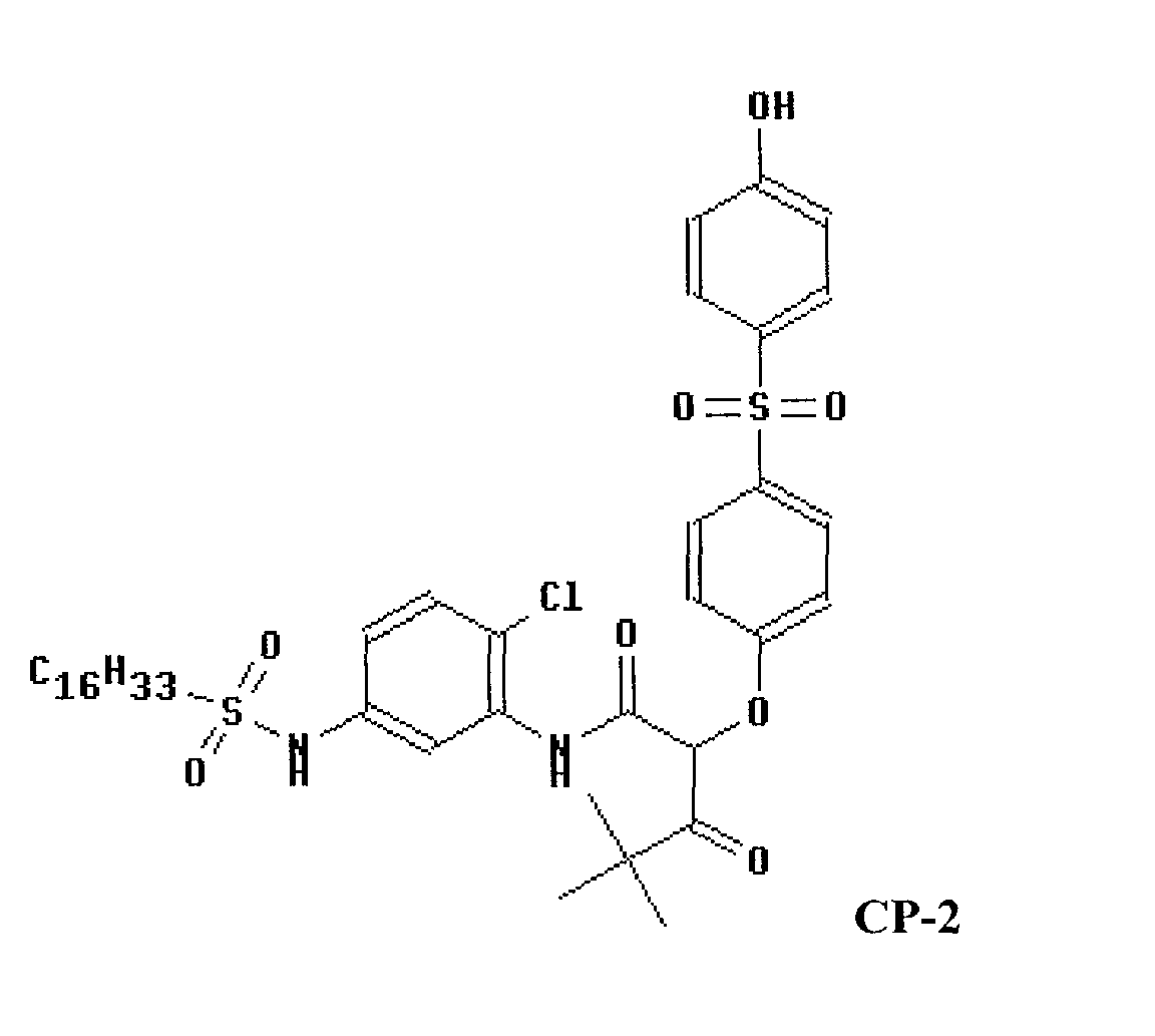


- These couplers can be dissolved, for example, in either of the following types of ionic liquids to give oils that can be dispersed in a photothermographic imaging layer:


- Some couplers do not readily dissolve directly in ionic liquids. However, if a suitable conventional coupler solvent (not an ionic liquid) is used to dissolve the coupler, a significant fraction (for example as much as 25% or more by weight) of the ionic liquid can then be added in order to obtain an oil comprised of three components: the coupler, the conventional coupler solvent, and the ionic liquid. Some examples of couplers that give oils when mixed as part of such a three-component mixture with an ionic liquid (such as one of IL-1 or IL-2) and a conventional coupler solvent (such as tricresyl phosphate) are the following:


- A typical photothermographic color negative film construction useful in the practice of the invention is illustrated by the following element, SCN-1:
Element SCN-1 SOC Surface Overcoat BU Blue Recording Layer Unit IL1 First Interlayer GU Green Recording Layer Unit IL2 Second Interlayer RU Red Recording Layer Unit AHU Antihalation Layer Unit S Support SOC Surface Overcoat - Details of support construction are well understood in the art. Examples of useful supports are poly(vinylacetal) film, polystyrene film, poly(ethyleneterephthalate) film, poly(ethylene naphthalate) film, polycarbonate film, and related films and resinous materials, as well as paper, cloth, glass, metal, and other supports that withstand the anticipated processing conditions. The element can contain additional layers, such as filter layers, interlayers, overcoat layers, subbing layers, antihalation layers and the like. Transparent and reflective support constructions, including subbing layers to enhance adhesion, are disclosed in Section XV of Research Disclosure, September 1996, Number 389, Item 38957 (hereafter referred to as ("Research Disclosure I").
- The photographic elements of the invention may also usefully include a magnetic recording material as described in Research Disclosure, Item 34390, November 1992, or a transparent magnetic recording layer such as a layer containing magnetic particles on the underside of a transparent support as in U.S. Patent No. 4,279,945, and U.S. Pat. No. 4,302,523.
- Each of blue, green and red recording layer units BU, GU and RU are formed of one or more hydrophilic colloid layers and contain at least one radiation-sensitive silver halide emulsion, including the developing agent and, in certain embodiments, the common dye image-forming coupler. It is preferred that the green, and red recording units are subdivided into at least two recording layer sub-units to provide increased recording latitude and reduced image granularity. In the simplest contemplated construction each of the layer units or layer sub-units consists of a single hydrophilic colloid layer containing emulsion and coupler. When coupler present in a layer unit or layer sub-unit is coated in a hydrophilic colloid layer other than an emulsion containing layer, the coupler containing hydrophilic colloid layer is positioned to receive oxidized color developing agent from the emulsion during development. In this case, the coupler containing layer is usually the next adjacent hydrophilic colloid layer to the emulsion containing layer.
- In order to ensure excellent image sharpness, and to facilitate manufacture and use in cameras, all of the sensitized layers are preferably positioned on a common face of the support. When in spool form, the element will be spooled such that when unspooled in a camera, exposing light strikes all of the sensitized layers before striking the face of the support carrying these layers. Further, to ensure excellent sharpness of images exposed onto the element, the total thickness of the layer units above the support should be controlled. Generally, the total thickness of the sensitized layers, interlayers and protective layers on the exposure face of the support are less than 35 µm. In another embodiment, sensitized layers disposed on two sides of a support, as in a duplitized film, can be employed.
- In a preferred embodiment of this invention, the processed photographic film contains only limited amounts of color masking couplers, incorporated permanent Dmin adjusting dyes and incorporated permanent antihalation dyes. Generally, such films contain color masking couplers in total amounts up to 0.6 mmol/m2, preferably in amounts up to 0.2 mmol/m2, more preferably in amounts up to 0.05 mmol/m2, and most preferably in amounts up to 0.01 mmol/m2.
- The incorporated permanent Dmin adjusting dyes are generally present in total amounts up to 0.2 mmol/m2, preferably in amounts up to 0.1 mmol/m2, more preferably in amounts up to 0.02 mmol/m2, and most preferably in amounts up to 0.005 mmol/m2.
- The incorporated permanent antihalation density is up to 0.6 in blue, green or red density, more preferably up to 0.3 in blue, green or red density, even more preferably up to 0.1 in blue, green or red density and most preferably up to 0.05 in blue, green or red Status M density.
- Limiting the amount of color masking couplers, permanent antihalation density and incorporated permanent Dmin adjusting dyes serves to reduce the optical density of the films, after processing, in the 350 to 750 nm range, and thus improves the subsequent scanning and digitization of the imagewise exposed and processed films.
- Overall, the limited Dmin and tone scale density enabled by controlling the quantity of incorporated color masking couplers, incorporated permanent Dmin adjusting dyes and antihalation and support optical density can serve to both limit scanning noise (which increases at high optical densities), and to improve the overall signal-to-noise characteristics of the film to be scanned. Relying on the digital correction step to provide color correction obviates the need for color masking couplers in the films.
- Any convenient selection from among conventional radiation-sensitive silver halide emulsions can be incorporated within the layer units and used to provide the spectral absorptances of the invention. Most commonly high bromide emulsions containing a minor amount of iodide are employed. To realize higher rates of processing, high chloride emulsions can be employed. Radiation-sensitive silver chloride, silver bromide, silver iodobromide, silver iodochloride, silver chlorobromide, silver bromochloride, silver iodochlorobromide and silver iodobromochloride grains are all contemplated. The grains can be either regular or irregular (e.g., tabular). Tabular grain emulsions, those in which tabular grains account for at least 50 (preferably at least 70 and optimally at least 90) percent of total grain projected area are particularly advantageous for increasing speed in relation to granularity. To be considered tabular a grain requires two major parallel faces with a ratio of its equivalent circular diameter (ECD) to its thickness of at least 2. Specifically preferred tabular grain emulsions are those having a tabular grain average aspect ratio of at least 5 and, optimally, greater than 8. Preferred mean tabular grain thicknesses are less than 0.3 µm (most preferably less than 0.2 µm). Ultrathin tabular grain emulsions, those with mean tabular grain thicknesses of less than 0.07 µm, are specifically contemplated. However, in a preferred embodiment, a preponderance low reflectivity grains are preferred. By preponderance is meant that greater than 50 % of the grain projected area is provided by low reflectivity silver halide grains. It is even more preferred that greater than 70% of the grain projected area be provided by low reflectivity silver halide grains. Low reflective silver halide grains are those having an average grain having a grain thickness > 0.06, preferably > 0.08, and more preferable > 0.10 microns. The grains preferably form surface latent images so that they produce negative images when processed in a surface developer in color negative film forms of the invention.
- Illustrations of conventional radiation-sensitive silver halide emulsions are provided by Research Disclosure I, cited above, I. Emulsion grains and their preparation. Chemical sensitization of the emulsions, which can take any conventional form, is illustrated in section IV. Chemical sensitization. Compounds useful as chemical sensitizers, include, for example, active gelatin, sulfur, selenium, tellurium, gold, platinum, palladium, iridium, osmium, rhenium, phosphorous, or combinations thereof. Chemical sensitization is generally carried out at pAg levels of from 5 to 10, pH levels of from 4 to 8, and temperatures of from 30 to 80°C. Spectral sensitization and sensitizing dyes, which can take any conventional form, are illustrated by section V. Spectral sensitization and desensitization. The dye may be added to an emulsion of the silver halide grains and a hydrophilic colloid at any time prior to (e.g., during or after chemical sensitization) or simultaneous with the coating of the emulsion on a photographic element. The dyes may, for example, be added as a solution in water or an alcohol or as a dispersion of solid particles. The emulsion layers also typically include one or more antifoggants or stabilizers, which can take any conventional form, as illustrated by section VII. Antifoggants and stabilizers.
- The silver halide grains to be used in the invention may be prepared according to methods known in the art, such as those described in Research Disclosure I, cited above, and James, The Theory of the Photographic Process. These include methods such as ammoniacal emulsion making, neutral or acidic emulsion making, and others known in the art. These methods generally involve mixing a water soluble silver salt with a water soluble halide salt in the presence of a protective colloid, and controlling the temperature, pAg, pH values, etc, at suitable values during formation of the silver halide by precipitation.
- In the course of grain precipitation one or more dopants (grain occlusions other than silver and halide) can be introduced to modify grain properties. For example, any of the various conventional dopants disclosed in Research Disclosure I, Section I. Emulsion grains and their preparation, subsection G. Grain modifying conditions and adjustments, paragraphs (3), (4) and (5), can be present in the emulsions of the invention. In addition it is specifically contemplated to dope the grains with transition metal hexacoordination complexes containing one or more organic ligands, as taught by Olm, et al., U.S. Patent 5,360,712.
- It is specifically contemplated to incorporate in the face centered cubic crystal lattice of the grains a dopant capable of increasing imaging speed by forming a shallow electron trap (hereinafter also referred to as a SET) as discussed in Research Disclosure Item 36736 published November 1994.
- The photographic elements of the present invention, as is typical, provide the silver halide in the form of an emulsion. Photographic emulsions generally include a vehicle for coating the emulsion as a layer of a photographic element. Useful vehicles include both naturally occurring substances such as proteins, protein derivatives, cellulose derivatives (e.g., cellulose esters), gelatin (e.g., alkali-treated gelatin such as cattle bone or hide gelatin, or acid treated gelatin such as pigskin gelatin), deionized gelatin, gelatin derivatives (e.g., acetylated gelatin, phthalated gelatin, and the like), and others as described in Research Disclosure, I. Also useful as vehicles or vehicle extenders are hydrophilic water-permeable colloids. These include synthetic polymeric peptizers, carriers, and/or binders such as poly(vinyl alcohol), poly(vinyl lactams), acrylamide polymers, polyvinyl acetals, polymers of alkyl and sulfoalkyl acrylates and methacrylates, hydrolyzed polyvinyl acetates, polyamides, polyvinyl pyridine, methacrylamide copolymers. The vehicle can be present in the emulsion in any amount useful in photographic emulsions. The emulsion can also include any of the addenda known to be useful in photographic emulsions.
- While any useful quantity of light sensitive silver, as silver halide, can be employed in the elements useful in this invention, it is preferred that the total quantity be not more than 4.5 g/m2 of silver, preferably less. Silver quantities of less than 4.0 g/m2 are preferred, and silver quantities of less than 3.5 g/m2 are even more preferred. The lower quantities of silver improve the optics of the elements, thus enabling the production of sharper pictures using the elements. These lower quantities of silver are additionally important in that they enable rapid development and desilvering of the elements. Conversely, a silver coating coverage of at least 1.0 g of coated silver per m2 of support surface area in the element is necessary to realize an exposure latitude of at least 2.7 log E while maintaining an adequately low graininess position for pictures intended to be enlarged. Silver coverages in excess of 1.5 g/m2 are preferred while silver coverages in excess of 2.5 g/m2 are more preferred.
- It is common practice to coat one, two or three separate emulsion layers within a single dye image-forming layer unit. When two or more emulsion layers are coated in a single layer unit, they are typically chosen to differ in sensitivity. When a more sensitive emulsion is coated over a less sensitive emulsion, a higher speed is realized than when the two emulsions are blended. When a less sensitive emulsion is coated over a more sensitive emulsion, a higher contrast is realized than when the two emulsions are blended. It is preferred that the most sensitive emulsion be located nearest the source of exposing radiation and the slowest emulsion be located nearest the support.
- One or more of the layer units of the invention is preferably subdivided into at least two, and more preferably three or more sub-unit layers. It is preferred that all light sensitive silver halide emulsions in the color recording unit have spectral sensitivity in the same region of the visible spectrum. In this embodiment, while all silver halide emulsions incorporated in the unit have spectral absorptance according to invention, it is expected that there are minor differences in spectral absorptance properties between them. In still more preferred embodiments, the sensitizations of the slower silver halide emulsions are specifically tailored to account for the light shielding effects of the faster silver halide emulsions of the layer unit that reside above them, in order to provide an imagewise uniform spectral response by the photographic recording material as exposure varies with low to high light levels. Thus higher proportions of peak light absorbing spectral sensitizing dyes may be desirable in the slower emulsions of the subdivided layer unit to account for on-peak shielding and broadening of the underlying layer spectral sensitivity.
- The interlayers IL1 and IL2 are hydrophilic colloid layers having as their primary function color contamination reduction-i.e., prevention of oxidized developing agent from migrating to an adjacent recording layer unit before reacting with dye-forming coupler. The interlayers are in part effective simply by increasing the diffusion path length that oxidized developing agent must travel. To increase the effectiveness of the interlayers to intercept oxidized developing agent, it is conventional practice to incorporate oxidized developing agent. Antistain agents (oxidized developing agent scavengers) can be selected from among those disclosed by Research Disclosure I, X. Dye image formers and modifiers, D. Hue modifiers/stabilization, paragraph (2). When one or more silver halide emulsions in GU and RU are high bromide emulsions and, hence have significant native sensitivity to blue light, it is preferred to incorporate a yellow filter, such as Carey Lea silver or a yellow processing solution decolorizable dye, in IL1. Suitable yellow filter dyes can be selected from among those illustrated by Research Disclosure I, Section VIII. Absorbing and scattering materials, B. Absorbing materials. In elements of the instant invention, magenta colored filter materials are absent from IL2 and RU.
- The antihalation layer unit AHU typically contains a processing solution removable or decolorizable light absorbing material, such as one or a combination of pigments and dyes. Suitable materials can be selected from among those disclosed in Research Disclosure I, Section VIII. Absorbing materials. A common alternative location for AHU is between the support S and the recording layer unit coated nearest the support.
- The surface overcoats SOC are hydrophilic colloid layers that are provided for physical protection of the color negative elements during handling and processing. Each SOC also provides a convenient location for incorporation of addenda that are most effective at or near the surface of the color negative element. In some instances the surface overcoat is divided into a surface layer and an interlayer, the latter functioning as spacer between the addenda in the surface layer and the adjacent recording layer unit. In another common variant form, addenda are distributed between the surface layer and the interlayer, with the latter containing addenda that are compatible with the adjacent recording layer unit. Most typically the SOC contains addenda, such as coating aids, plasticizers and lubricants, antistats and matting agents, such as illustrated by Research Disclosure I, Section IX. Coating physical property modifying addenda. The SOC overlying the emulsion layers additionally preferably contains an ultraviolet absorber, such as illustrated by Research Disclosure I, Section VI. UV dyes/optical brighteners/luminescent dyes, paragraph (1).
- Instead of the layer unit sequence of element SCN-1, alternative layer units sequences can be employed and are particularly attractive for some emulsion choices. Using high chloride emulsions and/or thin (<0.2 µm mean grain thickness) tabular grain emulsions all possible interchanges of the positions of BU, GU and RU can be undertaken without risk of blue light contamination of the minus blue records, since these emulsions exhibit negligible native sensitivity in the visible spectrum. For the same reason, it is unnecessary to incorporate blue light absorbers in the interlayers.
- When the emulsion layers within a dye image-forming layer unit differ in speed, it is conventional practice to limit the incorporation of dye image-forming coupler in the layer of highest speed to less than a stoichiometric amount, based on silver. The function of the highest speed emulsion layer is to create the portion of the characteristic curve just above the minimum density-i.e., in an exposure region that is below the threshold sensitivity of the remaining emulsion layer or layers in the layer unit. In this way, adding the increased granularity of the highest sensitivity speed emulsion layer to the dye image record produced is minimized without sacrificing imaging speed.
- In the foregoing discussion the blue, green and red recording layer units are described as containing developing agents for producing yellow, magenta and cyan dyes, respectively, as is conventional practice in color negative elements used for printing. The invention can be suitably applied to conventional color negative construction as illustrated. Color reversal film construction would take a similar form, with the exception that colored masking couplers would be completely absent; in typical forms, development inhibitor releasing couplers would also be absent. In preferred embodiments, the color negative elements are intended exclusively for scanning to produce three separate electronic color records. Thus the actual hue of the image dye produced is of no importance. What is essential is merely that the dye image produced in each of the layer units be differentiable from that produced by each of the remaining layer units. To provide this capability of differentiation it is contemplated that each of the layer units contain one or more dye image-forming couplers chosen to produce image dye having an absorption half-peak bandwidth lying in a different spectral region. It is immaterial whether the blue, green or red recording layer unit forms a yellow, magenta or cyan dye having an absorption half peak bandwidth in the blue, green or red region of the spectrum, as is conventional in a color negative element intended for use in printing, or an absorption half-peak bandwidth in any other convenient region of the spectrum, ranging from the near ultraviolet (300-400 nm) through the visible and through the near infrared (700-1200 nm), so long as the absorption half-peak bandwidths of the image dye in the layer units extend over substantially non-coextensive wavelength ranges. The term "substantially non-coextensive wavelength ranges" means that each image dye exhibits an absorption half-peak band width that extends over at least a 25 (preferably 50) nm spectral region that is not occupied by an absorption half-peak band width of another image dye. Ideally the image dyes exhibit absorption half-peak band widths that are mutually exclusive.
- When a layer unit contains two or more emulsion layers differing in speed, it is possible to lower image granularity in the image to be viewed, recreated from an electronic record, by forming in each emulsion layer of the layer unit a dye image which exhibits an absorption half-peak band width that lies in a different spectral region than the dye images of the other emulsion layers of layer unit. This technique is particularly well suited to elements in which the layer units are divided into sub-units that differ in speed. This allows multiple electronic records to be created for each layer unit, corresponding to the differing dye images formed by the emulsion layers of the same spectral sensitivity. The digital record formed by scanning the dye image formed by an emulsion layer of the highest speed is used to recreate the portion of the dye image to be viewed lying just above minimum density. At higher exposure levels second and, optionally, third electronic records can be formed by scanning spectrally differentiated dye images formed by the remaining emulsion layer or layers. These digital records contain less noise (lower granularity) and can be used in recreating the image to be viewed over exposure ranges above the threshold exposure level of the slower emulsion layers. This technique for lowering granularity is disclosed in greater detail by Sutton U.S. Patent 5,314,794.
- Each layer unit of the color negative elements of the invention produces a dye image characteristic curve gamma of less than 1.5, which facilitates obtaining an exposure latitude of at least 2.7 log E. A minimum acceptable exposure latitude of a multicolor photographic element is that which allows accurately recording the most extreme whites (e.g., a bride's wedding gown) and the most extreme blacks (e.g., a bride groom's tuxedo) that are likely to arise in photographic use. An exposure latitude of 2.6 log E can just accommodate the typical bride and groom wedding scene. An exposure latitude of at least 3.0 log E is preferred, since this allows for a comfortable margin of error in exposure level selection by a photographer. Even larger exposure latitudes are specifically preferred, since the ability to obtain accurate image reproduction with larger exposure errors is realized. Whereas in color negative elements intended for printing, the visual attractiveness of the printed scene is often lost when gamma is exceptionally low, when color negative elements are scanned to create digital dye image records, contrast can be increased by adjustment of the electronic signal information. When the elements of the invention are scanned using a reflected beam, the beam travels through the layer units twice. This effectively doubles gamma (ΔD ÷ Δ log E) by doubling changes in density (ΔD). Thus, gamma's as low as 1.0 or even 0.6 are contemplated and exposure latitudes of up to 5.0 log E or higher are feasible. Gammas above 0.25 are preferred and gammas above 0.30 are more preferred. Gammas of between 0.4 and 0.5 are especially preferred.
- In a preferred embodiment the dye image is formed by the use of an incorporated developing agent, in reactive association with each color layer. More preferably, the incorporated developing agent is a blocked developing agent.
- Examples of blocking groups that can be used in photographic elements of the present invention include, but are not limited to, the blocking groups described in U.S. Pat. No. 3,342,599, to Reeves; Research Disclosure (129 (1975) pp. 27-30) published by Kenneth Mason Publications, Ltd., Dudley Annex, 12a North Street, Emsworth, Hampshire P010 7DQ, ENGLAND; U.S. Pat. No. 4,157,915, to Hamaoka et al.; U.S. Pat. No. 4, 060,418, to Waxman and Mourning; and in U.S. Pat. No. 5,019,492. Other examples of blocking groups that can be used in photographic elements of the present invention include, but are not limited to, the blocking groups described in U.S. Pat. No. 3,342,599, to Reeves; Research Disclosure (129 (1975) pp. 27-30) published by Kenneth Mason Publications, Ltd., Dudley Annex, 12a North Street, Emsworth, Hampshire P010 7DQ, ENGLAND; U.S. Pat. No. 4,157,915, to Hamaoka et al.; U.S. Pat. No. 4, 060,418, to Waxman and Mourning; and in U.S. Pat. No. 5,019,492. Particularly useful are those blocking groups described in U.S. Application Serial No. 09/476,234, filed December 30, 1999, IMAGING ELEMENT CONTAINING A BLOCKED PHOTOGRAPICALLY USEFUL COMPOUND; U.S. Application Serial No. 09/475,691, filed December 30, 1999, IMAGING ELEMENT CONTAINING A BLOCKED PHOTOGRAPHICALLY USEFUL COMPOUND; U.S. Application Serial No. 09/475,703, filed December 30, 1999, IMAGING ELEMENT CONTAINING A BLOCKED PHOTOGRAPHICALLY USEFUL COMPOUND; U.S. Application Serial No. 09/475,690, filed December 30, 1999, IMAGING ELEMENT CONTAINING A BLOCKED PHOTOGRAPHICALLY USEFUL COMPOUND; and U.S. Application Serial No. 09/476,233, filed December 30, 1999, PHOTOGRAPHIC OR PHOTOTHERMOGRAPHIC ELEMENT CONTAINING A BLOCKED PHOTOGRAPHICALLY USEFUL COMPOUND. In one embodiment of the invention, the blocked developer may be represented by the following Structure I:
- DEV is a silver-halide color developing agent according to the present invention;
- LINK 1 and LINK 2 are linking groups;
- TIME is a timing group;
- l is 0 or 1;
- m is 0, 1, or 2;
- n is 0 or 1;
- l + n is 1 or 2;
- B is a blocking group or B is:
-
- In a preferred embodiment of the invention, LINK 1 or LINK 2 are of structure II:wherein

- X represents carbon or sulfur;
- Y represents oxygen, sulfur of N-R1, where R1 is substituted or unsubstituted alkyl or substituted or unsubstituted aryl;
- p is 1 or 2;
- Z represents carbon, oxygen or sulfur;
- r is 0 or 1;
with the proviso that when X is carbon, both p and r are 1, when X is sulfur, Y is oxygen, p is 2 and r is 0; - # denotes the bond to PUG (for LINK 1) or TIME (for LINK 2):
- $ denotes the bond to TIME (for LINK 1) or T(t) substituted carbon (for LINK 2).
-
- Illustrative linking groups include, for example,

- TIME is a timing group. Such groups are well-known in the art such as (1) groups utilizing an aromatic nucleophilic substitution reaction as disclosed in U.S. Patent No. 5,262,291; (2) groups utilizing the cleavage reaction of a hemiacetal (U.S. Pat. No. 4,146,396, Japanese Applications 60-249148; 60-249149); (3) groups utilizing an electron transfer reaction along a conjugated system (U.S. Pat. No. 4,409,323; 4, 421,845; Japanese Applications 57-188035; 58-98728; 58-209736; 58-209738); and (4) groups using an intramolecular nucleophilic substitution reaction (U.S. Pat. No. 4,248,962).
- A number of modifications of color negative elements have been suggested for accommodating scanning, as illustrated by Research Disclosure I, Section XIV. Scan facilitating features. These systems to the extent compatible with the color negative element constructions described above are contemplated for use in the practice of this invention.
- It is also contemplated that the imaging element of this invention may be used with non-conventional sensitization schemes. For example, instead of using imaging layers sensitized to the red, green, and blue regions of the spectrum, the light-sensitive material may have one white-sensitive layer to record scene luminance, and two color-sensitive layers to record scene chrominance. Following development, the resulting image can be scanned and digitally reprocessed to reconstruct the full colors of the original scene as described in U.S.5,962,205. The imaging element may also comprise a pan-sensitized emulsion with accompanying color-separation exposure. In this embodiment, the developers of the invention would give rise to a colored or neutral image that, in conjunction with the separation exposure, would enable full recovery of the original scene color values. In such an element, the image may be formed by either developed silver density, a combination of one or more conventional couplers, or "black" couplers such as resorcinol couplers. The separation exposure may be made either sequentially through appropriate filters, or simultaneously through a system of spatially discreet filter elements (commonly called a "color filter array").
- The imaging element of the invention may also be a black and white image-forming material comprised, for example, of a pan-sensitized silver halide emulsion and a developer of the invention. In this embodiment, the image may be formed by developed silver density following processing, or by a coupler that generates a dye which can be used to carry the neutral image tone scale.
- When conventional yellow, magenta, and cyan image dyes are formed to read out the recorded scene exposures following chemical development of conventional exposed color photographic materials, the response of the red, green, and blue color recording units of the element can be accurately discerned by examining their densities. Densitometry is the measurement of transmitted light by a sample using selected colored filters to separate the imagewise response of the RGB image dye forming units into relatively independent channels. It is common to use Status M filters to gauge the response of color negative film elements intended for optical printing, and Status A filters for color reversal films intended for direct transmission viewing. In integral densitometry, the unwanted side and tail absorptions of the imperfect image dyes leads to a small amount of channel mixing, where part of the total response of, for example, a magenta channel may come from off-peak absorptions of either the yellow or cyan image dyes records, or both, in neutral characteristic curves. Such artifacts may be negligible in the measurement of a film's spectral sensitivity. By appropriate mathematical treatment of the integral density response, these unwanted off-peak density contributions can be completely corrected providing analytical densities, where the response of a given color record is independent of the spectral contributions of the other image dyes. Analytical density determination has been summarized in the SPSE Handbook of Photographic Science and Engineering, W. Thomas, editor, John Wiley and Sons, New York, 1973, Section 15.3, Color Densitometry, pp. 840-848.
- Image noise can be reduced, where the images are obtained by scanning exposed and processed color negative film elements to obtain a manipulatable electronic record of the image pattern, followed by reconversion of the adjusted electronic record to a viewable form. Image sharpness and colorfulness can be increased by designing layer gamma ratios to be within a narrow range while avoiding or minimizing other performance deficiencies, where the color record is placed in an electronic form prior to recreating a color image to be viewed. Whereas it is impossible to separate image noise from the remainder of the image information, either in printing or by manipulating an electronic image record, it is possible by adjusting an electronic image record that exhibits low noise, as is provided by color negative film elements with low gamma ratios, to improve overall curve shape and sharpness characteristics in a manner that is impossible to achieve by known printing techniques. Thus, images can be recreated from electronic image records derived from such color negative elements that are superior to those similarly derived from conventional color negative elements constructed to serve optical printing applications. The excellent imaging characteristics of the described element are obtained when the gamma ratio for each of the red, green and blue color recording units is less than 1.2. In a more preferred embodiment, the red, green, and blue light sensitive color forming units each exhibit gamma ratios of less than 1.15. In an even more preferred embodiment, the red and blue light sensitive color forming units each exhibit gamma ratios of less than 1.10. In a most preferred embodiment, the red, green, and blue light sensitive color forming units each exhibit gamma ratios of less than 1.10. In all cases, it is preferred that the individual color unit(s) exhibit gamma ratios of less than 1.15, more preferred that they exhibit gamma ratios of less than 1.10 and even more preferred that they exhibit gamma ratios of less than 1.05. In a like vein, it is preferred that the gamma ratios be greater than 0.8, more preferred that they be greater than 0.85 and most preferred that they be greater than 0.9. The gamma ratios of the layer units need not be equal. These low values of the gamma ratio are indicative of low levels of interlayer interaction, also known as interlayer interimage effects, between the layer units and are believed to account for the improved quality of the images after scanning and electronic manipulation. The apparently deleterious image characteristics that result from chemical interactions between the layer units need not be electronically suppressed during the image manipulation activity. The interactions are often difficult if not impossible to suppress properly using known electronic image manipulation schemes.
- Elements having excellent light sensitivity are best employed in the practice of this invention. The elements should have a sensitivity of at least about ISO 50, preferably have a sensitivity of at least about ISO 100, and more preferably have a sensitivity of at least about ISO 200. Elements having a sensitivity of up to ISO 3200 or even higher are specifically contemplated. The speed, or sensitivity, of a color negative photographic element is inversely related to the exposure required to enable the attainment of a specified density above fog after processing. Photographic speed for a color negative element with a gamma of 0.65 in each color record has been specifically defined by the American National Standards Institute (ANSI) as ANSI Standard Number PH 2.27-1981 (ISO (ASA Speed)) and relates specifically the average of exposure levels required to produce a density of 0.15 above the minimum density in each of the green light sensitive and least sensitive color recording unit of a color film. This definition conforms to the International Standards Organization (ISO) film speed rating. For the purposes of this application, if the color unit gammas differ from 0.65, the ASA or ISO speed is to be calculated by linearly amplifying or deamplifying the gamma vs. log E (exposure) curve to a value of 0.65 before determining the speed in the otherwise defined manner.
- The present invention also contemplates the use of photothermographic elements of the present invention in what are often referred to as single use cameras (or "film with lens" units). These cameras are sold with film preloaded in them and the entire camera is returned to a processor with the exposed film remaining inside the camera. The one-time-use cameras employed in this invention can be any of those known in the art. These cameras can provide specific features as known in the art such as shutter means, film winding means, film advance means, waterproof housings, single or multiple lenses, lens selection means, variable aperture, focus or focal length lenses, means for monitoring lighting conditions, means for adjusting shutter times or lens characteristics based on lighting conditions or user provided instructions, and means for camera recording use conditions directly on the film. These features include, but are not limited to: providing simplified mechanisms for manually or automatically advancing film and resetting shutters as described at Skarman, U.S. Patent 4,226,517; providing apparatus for automatic exposure control as described at Matterson et al, U S. Patent 4,345,835; moisture-proofing as described at Fujimura et al, U.S. Patent 4,766,451; providing internal and external film casings as described at Ohmura et al, U.S. Patent 4,751,536; providing means for recording use conditions on the film as described at Taniguchi et al, U.S. Patent 4,780,735; providing lens fitted cameras as described at Arai, U.S. Patent 4,804,987; providing film supports with superior anti-curl properties as described at Sasaki et al, U.S. Patent 4,827,298; providing a viewfinder as described at Ohmura et al, U.S. Patent 4,812,863; providing a lens of defined focal length and lens speed as described at Ushiro et al, U.S. Patent 4,812,866; providing multiple film containers as described at Nakayama et al, U.S. Patent 4,831,398 and at Ohmura et al, U.S. Patent 4,833,495; providing films with improved anti-friction characteristics as described at Shiba, U.S. Patent 4,866,469; providing winding mechanisms, rotating spools, or resilient sleeves as described at Mochida, U.S. Patent 4,884,087; providing a film patrone or cartridge removable in an axial direction as described by Takei et al at U.S. Patents 4,890,130 and 5,063,400; providing an electronic flash means as described at Ohmura et al, U.S. Patent 4,896,178; providing an externally operable member for effecting exposure as described at Mochida et al, U.S. Patent 4,954,857; providing film support with modified sprocket holes and means for advancing said film as described at Murakami, U.S. Patent 5,049,908; providing internal mirrors as described at Hara, U.S. Patent 5,084,719; and providing silver halide emulsions suitable for use on tightly wound spools as described at Yagi et al, European Patent Application 0,466,417 A.
- While the film may be mounted in the one-time-use camera in any manner known in the art, it is especially preferred to mount the film in the one-time-use camera such that it is taken up on exposure by a thrust cartridge. Thrust cartridges are disclosed by Kataoka et al U.S. Patent 5,226,613; by Zander U.S. Patent 5,200,777; by Dowling et al U.S. Patent 5,031,852; and by Robertson et al U.S. Patent 4,834,306. Narrow bodied one-time-use cameras suitable for employing thrust cartridges in this way are described by Tobioka et al U.S. Patent 5,692,221.
- Cameras may contain a built-in processing capability, for example a heating element. Designs for such cameras including their use in an image capture and display system are disclosed in Stoebe, et al., U.S. Patent Application Serial No. 09/388,573 filed September 1, 1999. The use of a one-time use camera as disclosed in said application is particularly preferred in the practice of this invention.
- Photographic elements of the present invention are preferably imagewise exposed using any of the known techniques, including those described in Research Disclosure I, Section XVI. This typically involves exposure to light in the visible region of the spectrum, and typically such exposure is of a live image through a lens, although exposure can also be exposure to a stored image (such as a computer stored image) by means of light emitting devices (such as light emitting diodes, CRT and the like). The photothermographic elements are also exposed by means of various forms of energy, including ultraviolet and infrared regions of the electromagnetic spectrum as well as electron beam and beta radiation, gamma ray, x-ray, alpha particle, neutron radiation and other forms of corpuscular wave-like radiant energy in either non-coherent (random phase) or coherent (in phase) forms produced by lasers. Exposures are monochromatic, orthochromatic, or panchromatic depending upon the spectral sensitization of the photographic silver halide.
- The elements as discussed above may serve as origination material for some or all of the following processes: image scanning to produce an electronic rendition of the capture image, and subsequent digital processing of that rendition to manipulate, store, transmit, output, or display electronically that image.
- As mentioned above, the photographic elements of the present invention can be photothermographic elements of the type described in Research Disclosure 17029 are included by reference. The photothermographic elements may be of type A or type B as disclosed in Research Disclosure I. Type A elements contain in reactive association a photosensitive silver halide, a reducing agent or developer, an activator, and a coating vehicle or binder. In these systems development occurs by reduction of silver ions in the photosensitive silver halide to metallic silver. Type B systems can contain all of the elements of a type A system in addition to a salt or complex of an organic compound with silver ion. In these systems, this organic complex is reduced during development to yield silver metal. The organic silver salt will be referred to as the silver donor. References describing such imaging elements include, for example, U.S. Patents 3,457,075; 4,459,350; 4,264,725 and 4,741,992.
- A photothermographic element comprises a photosensitive component that consists essentially of photographic silver halide. In the type B photothermographic material it is believed that the latent image silver from the silver halide acts as a catalyst for the described image-forming combination upon processing. In these systems, a preferred concentration of photographic silver halide is within the range of 0.01 to 100 moles of photographic silver halide per mole of silver donor in the photothermographic material.
- The Type B photothermographic element comprises an oxidation-reduction image forming combination that contains an organic silver salt oxidizing agent. The organic silver salt is a silver salt which is comparatively stable to light, but aids in the formation of a silver image when heated to 80 °C or higher in the presence of an exposed photocatalyst (i.e., the photosensitive silver halide) and a reducing agent.
- Suitable organic silver salts include silver salts of organic compounds having a carboxyl group. Preferred examples thereof include a silver salt of an aliphatic carboxylic acid and a silver salt of an aromatic carboxylic acid. Preferred examples of the silver salts of aliphatic carboxylic acids include silver behenate, silver stearate, silver oleate, silver laureate, silver caprate, silver myristate, silver palmitate, silver maleate, silver fumarate, silver tartarate, silver furoate, silver linoleate, silver butyrate and silver camphorate, mixtures thereof, etc. Silver salts that are substitutable with a halogen atom or a hydroxyl group can also be effectively used. Preferred examples of the silver salts of aromatic carboxylic acid and other carboxyl group-containing compounds include silver benzoate, a silver-substituted benzoate such as silver 3,5-dihydroxybenzoate, silver o-methylbenzoate, silver m-methylbenzoate, silver p-methylbenzoate, silver 2,4-dichlorobenzoate, silver acetamidobenzoate, silver p-phenylbenzoate, etc., silver gallate, silver tannate, silver phthalate, silver terephthalate, silver salicylate, silver phenylacetate, silver pyromellilate, a silver salt of 3-carboxymethyl-4-methyl-4-thiazoline-2-thione or the like as described in U.S. Pat. No. 3,785,830, and silver salt of an aliphatic carboxylic acid containing a thioether group as described in U.S. Pat. No. 3,330,663.
- Furthermore, a silver salt of a compound containing an imino group can be used. Preferred examples of these compounds include a silver salt of benzotriazole and a derivative thereof as described in Japanese patent publications 30270/69 and 18146/70, for example a silver salt of benzotriazole or methylbenzotriazole, etc., a silver salt of a halogen substituted benzotriazole, such as a silver salt of 5-chlorobenzotriazole, etc., a silver salt of 1,2,4-triazole, a silver salt of 3-amino-5-mercaptobenzyl-1,2,4-triazole, of 1H-tetrazole as described in U.S. Pat. No. 4,220,709, a silver salt of imidazole and an imidazole derivative, and the like.
- A second silver salt with a fog inhibiting property may also be used. The second silver organic salt, or thermal fog inhibitor, according to the present invention include silver salts of thiol or thione substituted compounds having a heterocyclic nucleus containing 5 or 6 ring atoms, at least one of which is nitrogen, with other ring atoms including carbon and up to two hetero-atoms selected from among oxygen, sulfur and nitrogen are specifically contemplated. Typical preferred heterocyclic nuclei include triazole, oxazole, thiazole, thiazoline, imidazoline, imidazole, diazole, pyridine and triazine. Preferred examples of these heterocyclic compounds include a silver salt of 2-mercaptobenzimidazole, a silver salt of 2-mercapto-5-aminothiadiazole, a silver salt of 5-carboxylic-1-methyl-2-phenyl-4-thiopyridine, a silver salt of mercaptotriazine, a silver salt of 2-mercaptobenzoxazole.
- The second organic silver salt may be a derivative of a thionamide. Specific examples would include but not be limited to the silver salts of 6-chloro-2-mercapto benzothiazole, 2-mercapto-thiazole, naptho(1,2-d)thiazole-2(1H)-thione,4-methyl-4-thiazoline-2-thione, 2-thiazolidinethione, 4,5-dimethyl-4-thiazoline-2-thione, 4-methyl-5-carboxy-4-thiazoline-2-thione, and 3-(2-carboxyethyl)-4-methyl-4-thiazoline-2-thione.
- Preferably, the second organic silver salt is a derivative of a mercapto-triazole. Specific examples would include, but not be limited to, a silver salt of 3-mercapto-4-phenyl-1,2,4 triazole and a silver salt of 3-mercapto-1,2,4-triazole.
- Most preferably the second organic salt is a derivative of a mercapto-tetrazole. In one preferred embodiment, a mercapto tetrazole compound useful in the present invention is represented by the following structure VI:wherein n is 0 or 1, and R is independently selected from the group consisting of substituted or unsubstituted alkyl, aralkyl, or aryl. Substituents include, but are not limited to, C1 to C6 alkyl, nitro, halogen, and the like, which substituents do not adversely affect the thermal fog inhibiting effect of the silver salt. Preferably, n is 1 and R is an alkyl having 1 to 6 carbon atoms or a substituted or unsubstituted phenyl group. Specific examples include but are not limited to silver salts of 1-phenyl-5-mercapto-tetrazole, 1-(3-acetamido)-5-mercapto-tetrazole, or 1-[3-(2-sulfo)benzamidophenyl]-5-mercapto-tetrazole.

- The photosensitive silver halide grains and the organic silver salt are coated so that they are in catalytic proximity during development. They can be coated in contiguous layers, but are preferably mixed prior to coating. Conventional mixing techniques are illustrated by Research Disclosure, Item 17029, cited above, as well as U.S. Pat. No. 3,700,458 and published Japanese patent applications Nos. 32928/75, 13224/74, 17216/75 and 42729/76.
- The photothermographic element can comprise a thermal solvent. Examples of useful thermal solvents. Examples of thermal solvents, for example, salicylanilide, phthalimide, N-hydroxyphthalimide, N-potassium-phthalimide, succinimide, N-hydroxy-1,8-naphthalimide, phthalazine, 1-(2H)-phthalazinone, 2-acetylphthalazinone, benzanilide, and benzenesulfonamide. Prior-art thermal solvents are disclosed, for example, in US Pat. No. 6,013,420 to Windender. Examples of toning agents and toning agent combinations are described in, for example, Research Disclosure, June 1978, Item No. 17029 and U.S. Patent No. 4,123,282.
- Photothermographic elements as described can contain addenda that are known to aid in formation of a useful image. The photothermographic element can contain development modifiers that function as speed increasing compounds, sensitizing dyes, hardeners, antistatic agents, plasticizers and lubricants, coating aids, brighteners, absorbing and filter dyes, such as described in Research Disclosure, December 1978, Item No. 17643 and Research Disclosure, June 1978, Item No. 17029.
- After imagewise exposure of a photothermographic element, the resulting latent image can be developed in a variety of ways. The simplest is by overall heating the element to thermal processing temperature. This overall heating merely involves heating the photothermographic element to a temperature within the range of 90°C to 180°C until a developed image is formed, such as within 0.5 to 60 seconds. By increasing or decreasing the thermal processing temperature a shorter or longer time of processing is useful. A preferred thermal processing temperature is within the range of 100°C to 160°C. Heating means known in the photothermographic arts are useful for providing the desired processing temperature for the exposed photothermographic element. The heating means is, for example, a simple hot plate, iron, roller, heated drum, microwave heating means, heated air, vapor or the like.
- It is contemplated that the design of the processor for the photothermographic element be linked to the design of the cassette or cartridge used for storage and use of the element. Further, data stored on the film or cartridge may be used to modify processing conditions or scanning of the element. Methods for accomplishing these steps in the imaging system are disclosed by Stoebe, et al., U.S. 6,062,746 and Szajewski, et al., U.S. 6,048,110, commonly assigned. The use of an apparatus whereby the processor can be used to write information onto the element, information which can be used to adjust processing, scanning, and image display is also envisaged. This system is disclosed in now allowed Stoebe, et al., U.S. Patent Applications Serial Nos. 09/206,914 filed December 7, 1998 and 09/333,092 filed June 15, 1999.
- Thermal processing is preferably carried out under ambient conditions of pressure and humidity. Conditions outside of normal atmospheric pressure and humidity are useful.
- The components of the photothermographic element can be in any location in the element that provides the desired image. If desired, one or more of the components can be in one or more layers of the element. For example, in some cases, it is desirable to include certain percentages of the reducing agent, toner, stabilizer and/or other addenda in the overcoat layer over the photothermographic image recording layer of the element. This, in some cases, reduces migration of certain addenda in the layers of the element.
- In view of advances in the art of scanning technologies, it has now become natural and practical for photothermographic color films such as disclosed in EP 0762 201 to be scanned, which can be accomplished without the necessity of removing the silver or silver-halide from the negative, although special arrangements for such scanning can be made to improve its quality. See, for example, Simmons US Patent 5,391,443.
- Nevertheless, the retained silver halide can scatter light, decrease sharpness and raise the overall density of the film thus leading to impaired scanning. Further, retained silver halide can printout to ambient/viewing/scanning light, render non-imagewise density, degrade signal-to noise of the original scene, and raise density even higher. Finally, the retained silver halide and organic silver salt can remain in reactive association with the other film chemistry, making the film unsuitable as an archival media. Removal or stabilization of these silver sources are necessary to render the PTG film to an archival state.
- Furthermore, the silver coated in the PTG film (silver halide, silver donor, and metallic silver) is unnecessary to the dye image produced, and this silver is valuable and the desire is to recover it is high.
- Thus, it may be desirable to remove, in subsequent processing steps, one or more of the silver containing components of the film: the silver halide, one or more silver donors, the silver-containing thermal fog inhibitor if present, and/or the silver metal. The three main sources are the developed metallic silver, the silver halide, and the silver donor. Alternately, it may be desirable to stabilize the silver halide in the photothermographic film. Silver can be wholly or partially stabilized/removed based on the total quantity of silver and/or the source of silver in the film.
- The removal of the silver halide and silver donor can be accomplished with a common fixing chemical as known in the photographic arts. Specific examples of useful chemicals include: thioethers, thioureas, thiols, thiones, thionamides, amines, quaternary amine salts, ureas, thiosulfates, thiocyanates, bisulfites, amine oxides, iminodiethanol -sulfur dioxide addition complexes, amphoteric amines, bis-sulfonylmethanes, and the carbocyclic and heterocyclic derivatives of these compounds. These chemicals have the ability to form a soluble complex with silver ion and transport the silver out of the film into a receiving vehicle. The receiving vehicle can be another coated layer (laminate) or a conventional liquid processing bath.
- The stabilization of the silver halide and silver donor can also be accomplished with a common stabilization chemical. The previously mentioned silver salt removal compounds can be employed in this regard. With stabilization, the silver is not necessarily removed from the film, although the fixing agent and stabilization agents could very well be a single chemical. The physical state of the stabilized silver is no longer in large (> 50 nm) particles as it was for the silver halide and silver donor, so the stabilized state is also advantaged in that light scatter and overall density is lower, rendering the image more suitable for scanning.
- The removal of the metallic silver is more difficult than removal of the silver halide and silver donor. In general, two reaction steps are involved. The first step is to bleach the metallic silver to silver ion. The second step may be identical to the removal/stabilization step(s) described for silver halide and silver donor above. Metallic silver is a stable state that does not compromise the archival stability of the PTG film. Therefore, if stabilization of the PTG film is favored over removal of silver, the bleach step can be skipped and the metallic silver left in the film. In cases where the metallic silver is removed, the bleach and fix steps can be done together (called a blix) or sequentially (bleach + fix).
- The process could involve one or more of the scenarios or permutations of steps. The steps can be done one right after another or can be delayed with respect to time and location. For instance, heat development and scanning can be done in a remote kiosk, then bleaching and fixing accomplished several days later at a retail photofinishing lab. In one embodiment, multiple scanning of images is accomplished. For example, an initial scan may be done for soft display or a lower cost hard display of the image after heat processing, then a higher quality or a higher cost secondary scan after stabilization is accomplished for archiving and printing, optionally based on a selection from the initial display.
- For illustrative purposes, a non-exhaustive list of photothermographic film processes involving a common dry heat development step are as follows:
- 1. heat development => scan => stabilize (for example, with a laminate) => scan => obtain returnable archival film.
- 2. heat development => fix bath => water wash => dry => scan => obtain returnable archival film
- 3. heat development => scan => blix bath => dry => scan => recycle all or part of the silver in film
- 4. heat development => bleach laminate => fix laminate => scan => (recycle all or part of the silver in film)
- 5. heat development => scan => blix bath => wash => fix bath => wash => dry => obtain returnable archival film
- 6. heat development => relatively rapid, low quality scan
- 7. heat development => bleach => wash => fix => wash => dry => relatively slow, high quality scan
-
- Photothermographic or photographic elements of the present invention can also be subjected to low volume processing ("substantially dry" or "apparently dry") which is defined as photographic processing where the volume of applied developer solution is between 0.1 to 10 times, preferably 0.5 to 10 times, the volume of solution required to swell the photographic element. This processing may take place by a combination of solution application, external layer lamination, and heating. The low volume processing system may contain any of the elements described above for Type I: Photothermographic systems. In addition, it is specifically contemplated that any components described in the preceding sections that are not necessary for the formation or stability of latent image in the origination film element can be removed from the film element altogether and contacted at any time after exposure for the purpose of carrying out photographic processing, using the methods described below.
- The Type II photothermographic element may receive some or all of the following three treatments:
- (I) Application of a solution directly to the film by any means, including spray, inkjet, coating, gravure process and the like.
- (II) Soaking of the film in a reservoir containing a processing solution. This process may also take the form of dipping or passing an element through a small cartridge.
- (III) Lamination of an auxiliary processing element to the imaging element. The laminate may have the purpose of providing processing chemistry, removing spent chemistry, or transferring image information from the latent image recording film element. The transferred image may result from a dye, dye precursor, or silver containing compound being transferred in a image-wise manner to the auxiliary processing element.
-
- Heating of the element during processing may be effected by any convenient means, including a simple hot plate, iron, roller, heated drum, microwave heating means, heated air, vapor, or the like. Heating may be accomplished before, during, after, or throughout any of the preceding treatments I - III. Heating may cause processing temperatures ranging from room temperature to 100 ° C.
- Once yellow, magenta, and cyan dye image records (or the like) have been formed in the processed photographic elements of the invention, conventional techniques can be employed for retrieving the image information for each color record and manipulating the record for subsequent creation of a color balanced viewable image. For example, it is possible to scan the photothermographic element successively within the blue, green, and red regions of the spectrum or to incorporate blue, green, and red light within a single scanning beam that is divided and passed through blue, green, and red filters to form separate scanning beams for each color record. A simple technique is to scan the photothermographic element point-by-point along a series of laterally offset parallel scan paths. The intensity of light passing through the element at a scanning point is noted by a sensor which converts radiation received into an electrical signal. Most generally this electronic signal is further manipulated to form a useful electronic record of the image. For example, the electrical signal can be passed through an analog-to-digital converter and sent to a digital computer together with location information required for pixel (point) location within the image. In another embodiment, this electronic signal is encoded with colorimetric or tonal information to form an electronic record that is suitable to allow reconstruction of the image into viewable forms such as computer monitor displayed images, television images, printed images, and so forth.
- It is contemplated that many of imaging elements of this invention will be scanned prior to the removal of silver halide from the element. The remaining silver halide yields a turbid coating, and it is found that improved scanned image quality for such a system can be obtained by the use of scanners that employ diffuse illumination optics. Any technique known in the art for producing diffuse illumination can be used. Preferred systems include reflective systems, that employ a diffusing cavity whose interior walls are specifically designed to produce a high degree of diffuse reflection, and transmissive systems, where diffusion of a beam of specular light is accomplished by the use of an optical element placed in the beam that serves to scatter light. Such elements can be either glass or plastic that either incorporate a component that produces the desired scattering, or have been given a surface treatment to promote the desired scattering.
- One of the challenges encountered in producing images from information extracted by scanning is that the number of pixels of information available for viewing is only a fraction of that available from a comparable classical photographic print. It is, therefore, even more important in scan imaging to maximize the quality of the image information available. Enhancing image sharpness and minimizing the impact of aberrant pixel signals (i.e., noise) are common approaches to enhancing image quality. A conventional technique for minimizing the impact of aberrant pixel signals is to adjust each pixel density reading to a weighted average value by factoring in readings from adjacent pixels, closer adjacent pixels being weighted more heavily.
- The elements of the invention can have density calibration patches derived from one or more patch areas on a portion of unexposed photographic recording material that was subjected to reference exposures, as described by Wheeler et al U.S. Patent 5,649,260, Koeng at al U.S. Patent 5,563,717, and by Cosgrove et al U.S. Patent 5,644,647.
- Illustrative systems of scan signal manipulation, including techniques for maximizing the quality of image records, are disclosed by Bayer U.S. Patent 4,553,156; Urabe et al U.S. Patent 4,591,923; Sasaki et al U.S. Patent 4,631,578; Alkofer U.S. Patent 4,654,722; Yamada et al U.S. Patent 4,670,793; Klees U.S. Patents 4,694,342 and 4,962,542; Powell U.S. Patent 4,805,031; Mayne et al U.S. Patent 4,829,370; Abdulwahab U.S. Patent 4,839,721; Matsunawa et al U.S. Patents 4,841,361 and 4,937,662; Mizukoshi et al U.S. Patent 4,891,713; Petilli U.S. Patent 4,912,569; Sullivan et al U.S. Patents 4,920,501 and 5,070,413; Kimoto et al U.S. Patent 4,929,979; Hirosawa et al U.S. Patent 4,972,256; Kaplan U.S. Patent 4,977,521; Sakai U.S. Patent 4,979,027; Ng U.S. Patent 5,003,494; Katayama et al U.S. Patent 5,008,950; Kimura et al U.S. Patent 5,065,255; Osamu et al U.S. Patent 5,051,842; Lee et al U.S. Patent 5,012,333; Bowers et al U.S. Patent 5,107,346; Telle U.S. Patent 5,105,266; MacDonald et al U.S. Patent 5,105,469; and Kwon et al U.S. Patent 5,081,692. Techniques for color balance adjustments during scanning are disclosed by Moore et al U.S. Patent 5,049,984 and Davis U.S. Patent 5,541,645.
- The digital color records once acquired are in most instances adjusted to produce a pleasingly color balanced image for viewing and to preserve the color fidelity of the image bearing signals through various transformations or renderings for outputting, either on a video monitor or when printed as a conventional color print. Preferred techniques for transforming image bearing signals after scanning are disclosed by Giorgianni et al U.S. Patent 5,267,030. Further illustrations of the capability of those skilled in the art to manage color digital image information are provided by Giorgianni and Madden Digital Color Management, Addison-Wesley, 1998.
The following examples are included for a further understanding of this invention. - This example illustrates the preparation of photographic coupler dispersions incorporating ionic liquids in accordance with the present invention. The 300 g batches of dispersion were prepared by combining a hydrophobic phase comprising 27 g of coupler Y-1 with 13.5 g of the solvent tricresylphospate with an aqueous phase of 27 g of bone gelatin, 2.1 g of either the anionic surfactant ALKANOL XC (DuPont) or a nonionic surfactant of the structure C12H25-S-(CH2CHCONH2)10-H, and 240 g of water. Prior to addition to the aqueous phase (50 °C), the hydrophobic phase was heated to 110 °C and mixing at the time of addition was provided by a SILVERSON rotor-stator mixer (2 min.). Following this mixing, the dispersion was homogenized in a MICROFLUIDIZER mixer (3 passes). Ionic liquids, if present, were 1-hexadecyl-3-methyl imidazolium tetrafluoroborate (IL-3) or 1-oleyl-3-methyl imidazolium tetrafluoroborate (IL-4) in the amount of 2.7 g added to the hydrophobic phase with an equal amount of tricresylphosphate omitted so as to preserve the total hydrophobic phase content of the dispersion.


- The resulting dispersions were evaluated microscopically for droplet size, as shown in TABLE 1 below.
Part Ionic liquid Droplet size 1a none small, <= 1 um 1b none small, <= 1 um 1c IL-3 small, <= 1 um 1d IL-4 small, <= 1 um - This example shows that satisfactory photographic coupler dispersions that incorporate ionic liquids can be prepared using a nonionic surfactant.

- In addition to the above dispersions, the following components were also used in the preparation of photothermographic coating examples:
- A slurry was milled in water containing developer D-1 and OLIN 10G as a surfactant. The OLIN 10G was added at a level of 10% by weight of the D-1. To the resulting slurry was added water and dry gelatin in order to bring the final concentrations to 13% D-17 and 4% gelatin. The gelatin was allowed to swell by mixing the components at 15°C for 90 minutes. After this swelling process, the gelatin was dissolved by bringing the mixture to 40°C for 10 minutes, followed by cooling to chill-set the dispersion.

- A dispersion of salicylanilide (MF-1) was media-milled to give a dispersion containing 30% salicylanilide, with 4% TRITON X-200 surfactant and 4% polyvinyl pyrrolidone added relative to the weight of salicylanilide. The dispersion was then diluted with water to provide a final salicylanilide concentration of 25%.

- A stirred reaction vessel was charged with 431 g of lime processed gelatin and 6569 g of distilled water. A solution containing 214 g of benzotriazole, 2150 g of distilled water, and 790 g of 2.5 molar sodium hydroxide was prepared (Solution B). The mixture in the reaction vessel was adjusted to a pAg of 7.25 and a pH of 8.00 by additions of Solution B, nitric acid, and sodium hydroxide as needed. A 4 l solution of 0.54 molar silver nitrate was added to the kettle at 250 cc/minute, and the pAg was maintained at 7.25 by a simultaneous addition of solution B. This process was continued until the silver nitrate solution was exhausted, at which point the mixture was concentrated by ultrafiltration. The resulting silver salt dispersion contained fine particles of silver benzotriazole.
- A stirred reaction vessel was charged with 431 g of lime processed gelatin and 6569 g of distilled water. A solution containing 320 g of 1-phenyl-5-mercaptotetrazole , 2044 g of distilled water, and 790 g of 2.5 molar sodium hydroxide was prepared (Solution B). The mixture in the reaction vessel was adjusted to a pAg of 7.25 and a pH of 8.00 by additions of Solution B, nitric acid, and sodium hydroxide as needed. A 4 l solution of 0.54 molar silver nitrate was added to the kettle at 250 cc/minute, and the pAg was maintained at 7.25 by a simultaneous addition of solution B. This process was continued until the silver nitrate solution was exhausted, at which point the mixture was concentrated by ultrafiltration. The resulting silver salt dispersion contained fine particles of the silver salt of 1-phenyl-5-mercaptotetrazole.
- A silver halide tabular emulsion with a composition of 96% silver bromide and 4% silver iodide was prepared by conventional means. The resulting emulsion had an equivalent circular diameter of 1.2 microns and a thickness of 0.11 microns. This emulsion was spectrally sensitized to green light by addition of a combination of dyes SM-1 and SM-2 at a ratio of 4.5:1 and then chemically sensitized for optimum performance.


- To demonstrate the benefit of incorporating ionic liquids into dispersions with dye forming couplers, photothermographic coatings were prepared on 4 mil polyethyleneterephthalate (PET) support using the above components at levels (laydowns) given in TABLE 2.
Developer D-1 0.75 g/sq m for D-1 Silver Salt SS-1 0.32 g Ag/sq m Silver Salt SS-2 0.32 g Ag/sq m Meltformer MF-1 0.86 g/sq m Coupler Y-1 0.64 g/sq m Emulsion E-1 0.54 g Ag/sq m Gelatin Binder 4.30 g/sq m Sample Dispersion Process Temperature Blue Dmin Blue Dmax Blue Dmax-Dmin 1 (comp.) 1a (no IL) 155 0.07 0.42 0.35 2 (comp.) 1b (no IL) 155 0.07 0.47 0.40 3 (inv.) 1c (IL-3) 155 0.07 0.64 0.57 4 (inv.) 1d (IL-4) 155 0.07 0.72 0.65 5 (comp.) 1a (no IL) 158 0.08 0.54 0.46 6 (comp.) 1b (no IL) 158 0.09 0.57 0.48 7 (inv.) 1c (IL-3) 158 0.09 0.76 0.67 8 (inv.) 1d (IL-4) 158 0.08 0.86 0.78 9 (comp.) 1a (no IL) 161 0.12 0.71 0.59 10 (comp.) 1b (no IL) 161 0.13 0.76 0.63 11 (inv.) 1c (IL-3) 161 0.13 1.01 0.88 12 (inv.) 1d (IL-4) 161 0.19 1.08 0.89 - As the data in TABLE 3 clearly show, the blue Dmax for coatings that contain a coupler dispersion prepared with an ionic liquid are significantly higher than those from which an ionic liquid is absent. The image discrimination (Dmax minus Dmin) is also improved. The advantage of the ionic liquid is also not restricted to one process temperature, since the improvement can be observed at several process temperatures.

Claims (17)
- A silver-halide color or monochrome photothermographic light-sensitive element comprising a support and, on the support, at least one imaging layer comprising a silver-halide emulsion, wherein said imaging layer comprises a dye-forming coupler dispersed in a hydrophobic organic phase that comprises an ionic liquid material.
- The light-sensitive element of claim 1, further comprising at least three light-sensitive color imaging layers which have their individual sensitivities in different wavelength regions, each of the imaging layers comprising a light sensitive silver emulsion, a binder, and a dye-providing coupler, and a blocked developer, the dyes formed from the dye-providing couplers in the layers being different in hue, therefore capable of forming at least three dye images of different visible or infra-red colors.
- The light-sensitive element of claim 1 wherein the element is a monochromatic film.
- The light-sensitive element of claim 1 wherein, during development, the coupler is capable of reacting with an incorporated developer in reactive association with the coupler to produce an indoaniline, azomethine, indamine or indophenol dye.
- The light-sensitive element of claim 1 wherein the ionic liquid material is selected from the group consisting of imidazolium compounds, pyrazolium compounds, pyridinium compounds, pyrimidinium compounds, tetraalkyl ammonium compounds, tetraalkyl phosphonium compounds, and mixtures thereof.
- The light-sensitive element of claim 1 wherein the ionic liquid material is selected from the group consisting of:(a) those of the general formulawherein R1 and R5 are independently an alkyl group and R2, R3, and R4 each, independently of the others, are hydrogen atoms or alkyl groups;
 (b) those of the general formulawherein R6 is an alkyl group and R7, R8, and R9 each, independently of the others, are hydrogen atoms or alkyl groups, and X is an anion,
 c) those of the general formula:wherein R11 is an alkyl group and each R10 is independently a hydrogen atom or a substituted or unsubstituted alkyl group, and X is an anion,
 (d) those of the general formulawherein R12 is an alkyl group and each R13 can be independently a hydrogen atom or substituted or unsubstituted alkyl group, and X is an anion, and
 (e) those of the general formulae:wherein R14, R15, R16, and R17 each, independently of the others, are alkyl groups, and X is an anion; and
 (f) mixtures thereof.
 - The light-sensitive element of claim 1 wherein the ionic liquid material is selected front the group consisting of 1,3-alkylimidazolium salts, N-alkyl pyridinium salts, and mixtures thereof.
- The light-sensitive element of claim 1 wherein the hydrophobic organic phase contains the ionic liquid material in an amount of from 0.5 to 500 percent by weight of the total coupler in the imaging layer.
- The light-sensitive element of claim 1 wherein the imaging layer contains the ionic liquid material in an amount of from 2 to 50 percent by weight of the total coupler in the imaging layer.
- The light-sensitive element of claim 1 wherein the hydrophobic organic phase containing the coupler further comprises an organic solvent.
- The light-sensitive element of claim 10 wherein the organic solvent is selected from the group consisting of phthalic ester compounds and phosphoric ester compounds.
- The light-sensitive element of claim 1 wherein the ionic liquid material has an anion selected from the group consisting of tetrafluoborate, nitrate, hexafluorophosphate, perchlorate, and mixtures thereof.
- The light-sensitive element of claim 1 wherein the ionic liquid material is selected from the group consisting of imidazolium compounds, pyrazolium compounds, pyridinium compounds, pyrimidinium compounds, tetraalkyl ammonium componnds, tetraalkyl phosphonium compounds, and mixtures thereof and the ionic liquid material has an anion selected from the group consisting of tetrafluoborate, nitrate, hexafluorophosphate, perchlorate, and mixtures thereof.
- A method of forming a multicolor or monochrome image in a silver-halide photothermographic element, which comprises reacting an oxidized developing agent with a dye-forming coupler in a dispersed hydrophobic organic phase comprising an effective amount of an ionic liquid material.
- The method according to claim 14 wherein the ionic liquid material is selected from the group consisting of imidazolium compounds, pyrazolium compounds, pyridinium compounds, pyrimidinium compounds, tetraalkyl ammonium compounds, tetraalkyl phosphonium compounds, and mixtures thereof.
- The method according to claim 14 wherein the hydrophobic organic phase contains the ionic liquid material in an amount of from 0.5 to 500 percent by weight of the coupler.
- A method according to claim 14 wherein the hydrophobic organic phase contains the ionic liquid in an amount of from 2 to 50 percent by weight of the coupler.
Applications Claiming Priority (2)
| Application Number | Priority Date | Filing Date | Title |
|---|---|---|---|
| US09/990,734 US6531270B1 (en) | 2001-11-21 | 2001-11-21 | Ionic liquids as coupler solvents in photothermographic systems |
| US990734 | 2001-11-21 |
Publications (1)
| Publication Number | Publication Date |
|---|---|
| EP1315033A1 true EP1315033A1 (en) | 2003-05-28 |
Family
ID=25536487
Family Applications (1)
| Application Number | Title | Priority Date | Filing Date |
|---|---|---|---|
| EP02079689A Withdrawn EP1315033A1 (en) | 2001-11-21 | 2002-11-11 | Ionic liquids as coupler solvents in photothermographic systems |
Country Status (3)
| Country | Link |
|---|---|
| US (1) | US6531270B1 (en) |
| EP (1) | EP1315033A1 (en) |
| JP (1) | JP2003167316A (en) |
Cited By (2)
| Publication number | Priority date | Publication date | Assignee | Title |
|---|---|---|---|---|
| EP2006321A1 (en) | 2007-06-20 | 2008-12-24 | Universidade Nova de Lisboa | Synthesis and application of a family of new materials resulting from the chemical cross-linking between gelatine and organic salts |
| CN111621062A (en) * | 2019-02-28 | 2020-09-04 | 中国科学院化学研究所 | Polysaccharide/silver halide composite material and preparation method and application thereof |
Families Citing this family (17)
| Publication number | Priority date | Publication date | Assignee | Title |
|---|---|---|---|---|
| US7763186B2 (en) * | 2002-06-21 | 2010-07-27 | Los Alamos National Security, Llc | Preparation and purification of ionic liquids and precursors |
| US6961168B2 (en) * | 2002-06-21 | 2005-11-01 | The Regents Of The University Of California | Durable electrooptic devices comprising ionic liquids |
| US20040214108A1 (en) * | 2003-04-25 | 2004-10-28 | Ray Kevin B. | Ionic liquids as dissolution inhibitors in imageable elements |
| US6942957B2 (en) * | 2003-07-17 | 2005-09-13 | Kodak Polychrome Graphics Llc | Ionic liquids as developability enhancing agents in multilayer imageable elements |
| KR101130793B1 (en) | 2003-10-10 | 2012-03-28 | 주식회사 씨트리 | Ionic Liquid and Method for Preparing Other Ionic Liquid Using the Same |
| US7423164B2 (en) * | 2003-12-31 | 2008-09-09 | Ut-Battelle, Llc | Synthesis of ionic liquids |
| US8961407B2 (en) | 2004-07-21 | 2015-02-24 | Covidien Lp | Surgical port assembly |
| US7166421B2 (en) * | 2004-12-29 | 2007-01-23 | Eastman Kodak Company | Aqueous-based photothermographic materials containing tetrafluoroborate salts |
| US7438832B2 (en) * | 2005-03-29 | 2008-10-21 | Eastman Kodak Company | Ionic liquid and electronically conductive polymer mixtures |
| US7638058B2 (en) * | 2005-04-07 | 2009-12-29 | Matheson Tri-Gas | Fluid storage and purification method and system |
| FR2887681A1 (en) * | 2005-06-27 | 2006-12-29 | Univ Paris Curie | CONDUCTIVE FLUIDS CONTAINING MICROMETER MAGNETIC PARTICLES |
| US7163786B1 (en) | 2005-09-23 | 2007-01-16 | Eastman Kodak Company | Thermographic materials containing ionic liquids |
| US7153635B1 (en) | 2005-09-23 | 2006-12-26 | Eastman Kodak Company | Thermally developable materials processable at lower temperatures |
| KR101373387B1 (en) * | 2006-09-22 | 2014-03-13 | 바스프 에스이 | Magnetorheological formulation |
| WO2008055523A1 (en) * | 2006-11-07 | 2008-05-15 | Stichting Dutch Polymer Institute | Magnetic fluids and their use |
| US8481474B1 (en) | 2012-05-15 | 2013-07-09 | Ecolab Usa Inc. | Quaternized alkyl imidazoline ionic liquids used for enhanced food soil removal |
| US8716207B2 (en) | 2012-06-05 | 2014-05-06 | Ecolab Usa Inc. | Solidification mechanism incorporating ionic liquids |
Citations (2)
| Publication number | Priority date | Publication date | Assignee | Title |
|---|---|---|---|---|
| US4123273A (en) * | 1977-07-11 | 1978-10-31 | Eastman Kodak Company | Stable free radical nitroxyl bleaching agents for photographic processes |
| US6048388A (en) * | 1998-06-29 | 2000-04-11 | Schwarz; William M. | Ink compositions containing ionic liquid solvents |
Family Cites Families (1)
| Publication number | Priority date | Publication date | Assignee | Title |
|---|---|---|---|---|
| US6372829B1 (en) * | 1999-10-06 | 2002-04-16 | 3M Innovative Properties Company | Antistatic composition |
-
2001
- 2001-11-21 US US09/990,734 patent/US6531270B1/en not_active Expired - Fee Related
-
2002
- 2002-11-11 EP EP02079689A patent/EP1315033A1/en not_active Withdrawn
- 2002-11-21 JP JP2002337639A patent/JP2003167316A/en active Pending
Patent Citations (2)
| Publication number | Priority date | Publication date | Assignee | Title |
|---|---|---|---|---|
| US4123273A (en) * | 1977-07-11 | 1978-10-31 | Eastman Kodak Company | Stable free radical nitroxyl bleaching agents for photographic processes |
| US6048388A (en) * | 1998-06-29 | 2000-04-11 | Schwarz; William M. | Ink compositions containing ionic liquid solvents |
Cited By (3)
| Publication number | Priority date | Publication date | Assignee | Title |
|---|---|---|---|---|
| EP2006321A1 (en) | 2007-06-20 | 2008-12-24 | Universidade Nova de Lisboa | Synthesis and application of a family of new materials resulting from the chemical cross-linking between gelatine and organic salts |
| CN111621062A (en) * | 2019-02-28 | 2020-09-04 | 中国科学院化学研究所 | Polysaccharide/silver halide composite material and preparation method and application thereof |
| CN111621062B (en) * | 2019-02-28 | 2022-03-01 | 中国科学院化学研究所 | Polysaccharide/silver halide composite material and preparation method and application thereof |
Also Published As
| Publication number | Publication date |
|---|---|
| JP2003167316A (en) | 2003-06-13 |
| US6531270B1 (en) | 2003-03-11 |
Similar Documents
| Publication | Publication Date | Title |
|---|---|---|
| US6531273B1 (en) | Dispersions of ionic liquids for photothermographic systems and methods of making such systems | |
| US6531270B1 (en) | Ionic liquids as coupler solvents in photothermographic systems | |
| US6586166B1 (en) | Ionic liquids as addenda in photothermographic systems | |
| US6790569B2 (en) | Color photothermographic elements comprising phenolic thermal solvents | |
| US6426181B2 (en) | Mixtures of organic silver salts in color photothermographic systems | |
| US6599684B2 (en) | Color photothermographic element comprising a dye-forming system for forming a novel infrared dye | |
| US6610450B2 (en) | Thermally developable imaging system comprising a blocked color-forming agent in association with a hydroxy-substituted aromatic compound for promoting image formation | |
| US6517981B1 (en) | Color photothermographic element comprising a dye-forming system for forming a novel cyan dye | |
| US6620562B2 (en) | Color photographic element comprising a infrared dye-forming system in a blue image record | |
| US6570034B2 (en) | Blocked phenylenediamine developers for a color photographic element | |
| US6531271B1 (en) | Color photographic element comprising a multifunctional dye-forming coupler | |
| US6558890B1 (en) | Imaging element containing a blocked photographically useful compound activated by azolesulfonyl-assisted 1,2-elimination | |
| US6759187B1 (en) | Imaging element containing a blocked photographically useful compound | |
| US6638695B2 (en) | Method and material for photographic processing | |
| US6528241B1 (en) | Color photographic element comprising a multifunctional infrared-dye-forming coupler | |
| US6551768B2 (en) | Imaging element containing a blocked photographically useful compound | |
| US20050136364A1 (en) | Stable developer dispersions for color photothermographic systems |
Legal Events
| Date | Code | Title | Description |
|---|---|---|---|
| PUAI | Public reference made under article 153(3) epc to a published international application that has entered the european phase |
Free format text: ORIGINAL CODE: 0009012 |
|
| AK | Designated contracting states |
Designated state(s): AT BE BG CH CY CZ DE DK EE ES FI FR GB GR IE IT LI LU MC NL PT SE SK TR |
|
| AX | Request for extension of the european patent |
Extension state: AL LT LV MK RO SI |
|
| 17P | Request for examination filed |
Effective date: 20031103 |
|
| AKX | Designation fees paid |
Designated state(s): DE GB |
|
| 17Q | First examination report despatched |
Effective date: 20040108 |
|
| STAA | Information on the status of an ep patent application or granted ep patent |
Free format text: STATUS: THE APPLICATION IS DEEMED TO BE WITHDRAWN |
|
| 18D | Application deemed to be withdrawn |
Effective date: 20040519 |