EP1314942A2 - Construction of air separation units - Google Patents
Construction of air separation units Download PDFInfo
- Publication number
- EP1314942A2 EP1314942A2 EP02257721A EP02257721A EP1314942A2 EP 1314942 A2 EP1314942 A2 EP 1314942A2 EP 02257721 A EP02257721 A EP 02257721A EP 02257721 A EP02257721 A EP 02257721A EP 1314942 A2 EP1314942 A2 EP 1314942A2
- Authority
- EP
- European Patent Office
- Prior art keywords
- module
- modules
- library
- pressure column
- design
- Prior art date
- Legal status (The legal status is an assumption and is not a legal conclusion. Google has not performed a legal analysis and makes no representation as to the accuracy of the status listed.)
- Ceased
Links
Images

Classifications
-
- F—MECHANICAL ENGINEERING; LIGHTING; HEATING; WEAPONS; BLASTING
- F25—REFRIGERATION OR COOLING; COMBINED HEATING AND REFRIGERATION SYSTEMS; HEAT PUMP SYSTEMS; MANUFACTURE OR STORAGE OF ICE; LIQUEFACTION SOLIDIFICATION OF GASES
- F25J—LIQUEFACTION, SOLIDIFICATION OR SEPARATION OF GASES OR GASEOUS OR LIQUEFIED GASEOUS MIXTURES BY PRESSURE AND COLD TREATMENT OR BY BRINGING THEM INTO THE SUPERCRITICAL STATE
- F25J3/00—Processes or apparatus for separating the constituents of gaseous or liquefied gaseous mixtures involving the use of liquefaction or solidification
- F25J3/02—Processes or apparatus for separating the constituents of gaseous or liquefied gaseous mixtures involving the use of liquefaction or solidification by rectification, i.e. by continuous interchange of heat and material between a vapour stream and a liquid stream
- F25J3/04—Processes or apparatus for separating the constituents of gaseous or liquefied gaseous mixtures involving the use of liquefaction or solidification by rectification, i.e. by continuous interchange of heat and material between a vapour stream and a liquid stream for air
- F25J3/04248—Generation of cold for compensating heat leaks or liquid production, e.g. by Joule-Thompson expansion
- F25J3/04284—Generation of cold for compensating heat leaks or liquid production, e.g. by Joule-Thompson expansion using internal refrigeration by open-loop gas work expansion, e.g. of intermediate or oxygen enriched (waste-)streams
- F25J3/0429—Generation of cold for compensating heat leaks or liquid production, e.g. by Joule-Thompson expansion using internal refrigeration by open-loop gas work expansion, e.g. of intermediate or oxygen enriched (waste-)streams of feed air, e.g. used as waste or product air or expanded into an auxiliary column
- F25J3/04303—Lachmann expansion, i.e. expanded into oxygen producing or low pressure column
-
- F—MECHANICAL ENGINEERING; LIGHTING; HEATING; WEAPONS; BLASTING
- F25—REFRIGERATION OR COOLING; COMBINED HEATING AND REFRIGERATION SYSTEMS; HEAT PUMP SYSTEMS; MANUFACTURE OR STORAGE OF ICE; LIQUEFACTION SOLIDIFICATION OF GASES
- F25J—LIQUEFACTION, SOLIDIFICATION OR SEPARATION OF GASES OR GASEOUS OR LIQUEFIED GASEOUS MIXTURES BY PRESSURE AND COLD TREATMENT OR BY BRINGING THEM INTO THE SUPERCRITICAL STATE
- F25J3/00—Processes or apparatus for separating the constituents of gaseous or liquefied gaseous mixtures involving the use of liquefaction or solidification
- F25J3/02—Processes or apparatus for separating the constituents of gaseous or liquefied gaseous mixtures involving the use of liquefaction or solidification by rectification, i.e. by continuous interchange of heat and material between a vapour stream and a liquid stream
- F25J3/04—Processes or apparatus for separating the constituents of gaseous or liquefied gaseous mixtures involving the use of liquefaction or solidification by rectification, i.e. by continuous interchange of heat and material between a vapour stream and a liquid stream for air
- F25J3/04006—Providing pressurised feed air or process streams within or from the air fractionation unit
- F25J3/04078—Providing pressurised feed air or process streams within or from the air fractionation unit providing pressurized products by liquid compression and vaporisation with cold recovery, i.e. so-called internal compression
- F25J3/0409—Providing pressurised feed air or process streams within or from the air fractionation unit providing pressurized products by liquid compression and vaporisation with cold recovery, i.e. so-called internal compression of oxygen
-
- F—MECHANICAL ENGINEERING; LIGHTING; HEATING; WEAPONS; BLASTING
- F25—REFRIGERATION OR COOLING; COMBINED HEATING AND REFRIGERATION SYSTEMS; HEAT PUMP SYSTEMS; MANUFACTURE OR STORAGE OF ICE; LIQUEFACTION SOLIDIFICATION OF GASES
- F25J—LIQUEFACTION, SOLIDIFICATION OR SEPARATION OF GASES OR GASEOUS OR LIQUEFIED GASEOUS MIXTURES BY PRESSURE AND COLD TREATMENT OR BY BRINGING THEM INTO THE SUPERCRITICAL STATE
- F25J3/00—Processes or apparatus for separating the constituents of gaseous or liquefied gaseous mixtures involving the use of liquefaction or solidification
- F25J3/02—Processes or apparatus for separating the constituents of gaseous or liquefied gaseous mixtures involving the use of liquefaction or solidification by rectification, i.e. by continuous interchange of heat and material between a vapour stream and a liquid stream
- F25J3/04—Processes or apparatus for separating the constituents of gaseous or liquefied gaseous mixtures involving the use of liquefaction or solidification by rectification, i.e. by continuous interchange of heat and material between a vapour stream and a liquid stream for air
- F25J3/04406—Processes or apparatus for separating the constituents of gaseous or liquefied gaseous mixtures involving the use of liquefaction or solidification by rectification, i.e. by continuous interchange of heat and material between a vapour stream and a liquid stream for air using a dual pressure main column system
- F25J3/04412—Processes or apparatus for separating the constituents of gaseous or liquefied gaseous mixtures involving the use of liquefaction or solidification by rectification, i.e. by continuous interchange of heat and material between a vapour stream and a liquid stream for air using a dual pressure main column system in a classical double column flowsheet, i.e. with thermal coupling by a main reboiler-condenser in the bottom of low pressure respectively top of high pressure column
-
- F—MECHANICAL ENGINEERING; LIGHTING; HEATING; WEAPONS; BLASTING
- F25—REFRIGERATION OR COOLING; COMBINED HEATING AND REFRIGERATION SYSTEMS; HEAT PUMP SYSTEMS; MANUFACTURE OR STORAGE OF ICE; LIQUEFACTION SOLIDIFICATION OF GASES
- F25J—LIQUEFACTION, SOLIDIFICATION OR SEPARATION OF GASES OR GASEOUS OR LIQUEFIED GASEOUS MIXTURES BY PRESSURE AND COLD TREATMENT OR BY BRINGING THEM INTO THE SUPERCRITICAL STATE
- F25J3/00—Processes or apparatus for separating the constituents of gaseous or liquefied gaseous mixtures involving the use of liquefaction or solidification
- F25J3/02—Processes or apparatus for separating the constituents of gaseous or liquefied gaseous mixtures involving the use of liquefaction or solidification by rectification, i.e. by continuous interchange of heat and material between a vapour stream and a liquid stream
- F25J3/04—Processes or apparatus for separating the constituents of gaseous or liquefied gaseous mixtures involving the use of liquefaction or solidification by rectification, i.e. by continuous interchange of heat and material between a vapour stream and a liquid stream for air
- F25J3/04763—Start-up or control of the process; Details of the apparatus used
- F25J3/04866—Construction and layout of air fractionation equipments, e.g. valves, machines
- F25J3/0489—Modularity and arrangement of parts of the air fractionation unit, in particular of the cold box, e.g. pre-fabrication, assembling and erection, dimensions, horizontal layout "plot"
-
- F—MECHANICAL ENGINEERING; LIGHTING; HEATING; WEAPONS; BLASTING
- F25—REFRIGERATION OR COOLING; COMBINED HEATING AND REFRIGERATION SYSTEMS; HEAT PUMP SYSTEMS; MANUFACTURE OR STORAGE OF ICE; LIQUEFACTION SOLIDIFICATION OF GASES
- F25J—LIQUEFACTION, SOLIDIFICATION OR SEPARATION OF GASES OR GASEOUS OR LIQUEFIED GASEOUS MIXTURES BY PRESSURE AND COLD TREATMENT OR BY BRINGING THEM INTO THE SUPERCRITICAL STATE
- F25J2290/00—Other details not covered by groups F25J2200/00 - F25J2280/00
- F25J2290/10—Mathematical formulae, modeling, plot or curves; Design methods
Definitions
- This invention relates generally to air separation units, and more particularly, to a method of designing or building air separation units by using libraries containing different module designs, and to air separation units constructed according to such a method.
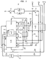
- FIG. 1 is a schematic illustration of a portion of a conventional air separation plant or unit 10 for the production of oxygen, nitrogen and/or argon.
- a main air compressor (MAC) 11 is used to produce a compressed air stream, e.g., at a pressure of 5-6 atmospheres, which is fed to pre-purification units (PPU) 12a-b in which carbon dioxide, water, trace hydrocarbons and other condensable substances are removed.
- PPU pre-purification units
- a main air stream 13a comprising between about 40% to about 80% of the air volume leaving the PPU, is fed to main heat exchanger (MHE) 14.
- Second stream 13b is passed to booster compressor 15 to produce a boosted air stream 13c having a pressure of about 10-70 atmospheres.
- the split ratio between the main air stream and the boosted air stream is a factor of a number of variables not the least of which is the desired product mix of the air separation plant.
- the boosted air is also fed to the MHE.
- the MHE internals are of standard design, and the MHE is operated in standard fashion.
- the main air exits the MHE as saturated vaporous main air stream 13d at a temperature of about -187 C (about -280 F).
- the boosted air exits the MHE as liquid boosted air stream 13e at a temperature of less than about -187 C.
- main air side stream 13f is withdrawn from main air 13a, and passed through the MHE.
- the temperature of the main air side stream 13f is lowered within the MHE to about -140 C (-220 F), and it is withdrawn as vaporous main air side stream 13g.
- This side stream is then passed through expander 16 to lower its temperature to less than about -180 C (-292 F), and then fed as expanded main air side stream 13h directly into low pressure column 22.
- Both the vaporous main air and liquid boosted air streams 13d and 13e are then fed to high pressure column (HPC) 17 at about -187 C for separation into an oxygen-enriched liquid stream and a nitrogen-enriched product.
- the gaseous nitrogen product stream 32 may be withdrawn from the upper section of the HPC at about -200 C (about -300 F).
- the HPC internals are of any standard construction, e.g., structured packing, distillation trays, etc., and the HPC is operated in a conventional fashion.
- An oxygen-rich liquid (RL) stream 18 is withdrawn from the lower section of the HPC 17, and comprises about 30-45 % by volume oxygen, with the remainder being nitrogen, argon and residual air components such as xenon, krypton, and so on.
- Poor liquid (PL) stream 29, essentially nitrogen, with various residual air components such as neon, etc., is withdrawn from the top section of the HPC 17.
- the split of these two liquid streams 18 and 29 is typically 55% by volume (or mole %) rich liquid and 45% by volume (or mole %) poor liquid. Both the rich and the poor liquid streams 18 and 29 are fed separately to subcooler 20, which is a refrigeration recovery heat exchange unit.
- the resulting subcooled streams 21a-b are fed to low pressure column (LPC) 22, which is typically located above and is thermally coupled with the HPC 17.
- LPC low pressure column
- These subcooled streams enter the LPC 22 at a temperature of about -207 C (about -316 F) and at a pressure of between about 1 and 2 atmospheres.
- liquid oxygen 23a collects at the bottom of the LPC 22 from where liquid oxygen product stream 23b is withdrawn.
- the purity of the liquid oxygen product stream can vary from about 95 % or less oxygen (low purity oxygen) up to and in excess of 99.9 % oxygen (high purity oxygen). The actual purity or composition of the liquid oxygen stream depends in large part upon the manner in which other parts of the air separation plant are operated.
- another liquid stream 30 also known as "intermediate liquid” stream
- Liquid oxygen generated in the lower section of the LPC 22 passes to the reboiler-condenser (R-C) 26, a portion of which is submerged within liquid oxygen in sump 23a.
- Gaseous nitrogen 27a from the HPC 17 is condensed in R-C 26 by indirect heat exchange with liquid oxygen in sump 23a, resulting in partially reboiling of the liquid oxygen.
- the condensed nitrogen stream 27b from R-C 26 enters the HPC 17.
- a poor liquid stream 29 is withdrawn from the HPC 17 and is passed to subcooler 20. This poor liquid stream can be withdrawn either from the same point as nitrogen stream 27b or it may be withdrawn several stages below the nitrogen stream 27b feedpoint.
- the liquid oxygen product stream 23b withdrawn from the sump 23a at a pressure of about 1 atmosphere can be transferred either directly, or optionally via subcooler 20, to a liquid oxygen (LOX) storage tank 32, and optionally, via subcooler 20.
- LOX liquid oxygen
- oxygen can be withdrawn from the LOX storage tank 32, and pressurized to about 5-70 atmospheres by a liquid oxygen pump P24.
- the pressurized LOX product stream then exchanges heat with the main and boosted air streams 13a and 13c in the MHE 14, resulting in the formation of gaseous oxygen product stream 23c, which is recovered at a pressure of about 5-70 atmospheres.
- Gaseous nitrogen waste stream 25a from the upper section of the LPC 22 is returned to the subcooler 20 for heat exchange with the rich and poor liquid streams from the HPC 17, and then discharged from the air separation unit after additional heat exchange with the main and boosted air streams in the MHE 14.
- a product nitrogen stream (not shown) may also be withdrawn from the LPC 22 and recovered as a nitrogen product after undergoing heat exchange in subcooler 20 and MHE 14.
- the plant supplier typically begins with an existing plant design that is closest to the required specifications and then modifies that design to fit the specifications.
- an existing plant design that is closest to the required specifications and then modifies that design to fit the specifications.
- a method of building an air separation plant comprising building a first module and a second module and interconnecting the first and second modules, wherein the first module is built to a first design preselected from a first library containing at least two different designs of said first module and the second design is built to a second design preselected from a second library containing at least two different designs of said second module, wherein each of said first module designs in said first library comprises a first set of interface points with substantially the same relative spatial coordinates as every other first module design in said first library, and each of said second module designs in said second library comprises a second set of interface points with substantially the same relative spatial coordinates as every other second module design in said second library.
- the invention also provides an air separation unit comprising a first module having a first set of interface points coupled to a second set of interface points of a second module; wherein said first module is of a design selected from a first library containing at least two different designs of said first module and said second module is of a design selected from a second library containing at least two different designs of said second module, each of said first module designs in said first library having a first set of interface points with substantially the same relative spatial coordinates as every other first module design in said first library and each of said second module designs in said second library having a second set of interface points with substantially the same relative spatial coordinates as every other second module design in said second library.
- the first module is preferably a high pressure column module.
- the high pressure column module is selected from a first library for coupling to the second module (for example, a main heat exchanger module) selected from a second library and for coupling to a low pressure column module selected from a third library.
- the first library contains different high pressure column modules, with each module having a first and second set of interface points, and each of the two sets of interface points has relative spatial coordinates that are substantially the same as every other high pressure column module in the first library.
- the second library contains different main heat exchanger modules, with each module having a third set of interface points with relative spatial coordinates that are substantially the same as every other main heat exchanger module in the second library, and the third set of interface points are designed for coupling to the first set of interface points on each of the high pressure column modules.
- an air separation plant is typically designed as follows. First, for each module in the air separation plant, particularly the heat exchange module and the rectification column modules, a plurality of different designs are made. The number of different designs of each module can be selected so as to cater to a wide range of different air flow rates into the plant, and/or to provide for different levels of thermodynamic operating efficiency (typically at different capital cost) for each selected air flow rate. Each design is made in essentially full external topographical detail and may consist of complete manufacturing drawings of the module concerned. The designs are kept for future use. A repository of designs of a particular module is referred to herein as a "library".
- module designs can therefore be selected from the libraries according to the rate at which each product is to be produced (or the rate at which air is to be separated), the purity requirement of the products, and according to the balance to be struck between the capital cost and the power consumption of the plant.
- modules in the libraries have predetermined designs prior to the selection process.
- additional module designs that are not available in the existing libraries may also be generated as appropriate.
- Each module is then built and the modules are interconnected to form the plant.
- the modules are built at a site or sites remote from the one where the plant is to be operated and are transported to the site of use, where they are interconnected.
- certain modules that perform one function have interfaces or connections with at least one other module that perform another function.
- the high pressure column module has a plurality of interfaces with both the low pressure column module and the main heat exchanger module.
- a plurality of designs of the same module have these interfaces at substantially the same predetermined relative spatial coordinates as one another.
- one design of a module may have the same relative spatial coordinates for its interface points as the other designs of the module or the relative spatial coordinates of one or more interface points of each design may be within predetermined loci.
- the relevant modules can be readily coupled together.
- a high pressure column module built according to any one of a number of different designs can be coupled to a main heat exchanger module and a low pressure column module, both built respectively according to any one of a number of different designs of each module.
- the interfaces between the respective modules are in substantially the same positions in the assembled plant. The ability to have these interfaces in substantially the same positions regardless of which modules are selected is an important aspect in the design of these modules.
- the method of design according to the invention can be extended beyond the rectification column and heat exchanger modules to other modules in the air separation plant.
- module means an assembly of components of an air separation unit, or a design representation thereof, that comprises at least three interface points. Each module is designed to be coupled, via its interface points, to at least one other module or equipment associated with the air separation unit.
- Interface point means a line end, e.g., a pipe end, of a module that delivers a fluid (gas or liquid), energy or information to a line or pipe end of another adjoining or otherwise connected module.
- a majority of the key interface points of the modules of this invention are designed to connect directly or through relatively straight and short connectors to the corresponding interface points of an other module or other equipment associated with a cryogenic air separation unit.
- Other line ends include electrical connections, control instrumentation cabling and the like.
- library of modules means a set or collection of two or more like modules designed to perform substantially the same function but differing from one another in size, capacity and/or efficiency.
- the modules of the library may refer to the hardware, i.e., physically existing, or a design representation, e.g., a blueprint, design specifications, a CAD/CAM drawing stored in a computer memory or other storage device, etc.
- the libraries comprise collections of designs stored on a computer from which the physical components are built as needed. In most cases, the modules in hardware or constructed form are not kept in inventory because most components are too large and/or expensive to simply build and store.
- Each module in a given library has at least one set of interface points having substantially the same topography as each other, i.e., the spatial coordinates or layout of the interface points relative to one another (or to a given axis) within the set is substantially the same for each module of the library.
- This set of interface points is used for coupling to corresponding interface points in a module from a different library.
- interface points having a relatively large "effective diameter” at least a majority, and preferably all, are designed to have the same topography for each module within a given library.
- This substantially fixed module interface point topography allows for a "plug-in/plug-out" feature of the modules.
- Other features commonly shared by modules within a given library include standardized component parts; interchangeability of various parts, e.g., gearing, bearings, and seals; a single, standardized layout with fixed location of customer interface coordinate locations.
- effective diameter means the cross-sectional length of the line end. If the cross-sectional shape of a line end is circular, then the cross-sectional length is a diameter. If the cross-sectional shape of the line end is a shape other than circular, e.g., oval, rectangular, etc., then the cross-sectional length is the longest length across the cross-section. Most line ends, particularly those with an effective diameter of four or more inches, are pipe ends with a circular cross-section.
- Such large lines e.g., pipes
- interface points with a smaller effective diameter e.g., less than about four inches
- the topography of these line ends need not be fixed to maintain the plug-in/plug-out feature of the modules. It is understood that the use of four inches as a reference for large versus small effective diameter is meant for illustrative purpose, and such a reference point may vary according to specific module designs and space constraints.
- module size or “module capacity” means the amount of fluid or energy that the module can process or transfer with a given period of time.
- size or capacity is typically measured in units of volume per time.
- the typical units are BTUs/hour.
- volume units are used for storage tanks, etc.
- An air separation plant may be described as comprising a number of subsystems, typically four subsystems, i.e., rotating equipment, warm equipment, cold equipment and site equipment.
- the first three of these subsystems are illustrated in Figure 2.
- Each subsystem may or may not be constructed in such manner as to constitute a complete, integrated assembly. While the warm and cold subsystems tend to be complete, integrated structures, i.e., all of their individual modules are connected to one another in a single assemblage, the rotating and site equipment subsystems tend to be just the opposite. Two or more components of these latter two subsystems are usually separate and apart from one another.
- the rotating equipment subsystem is likely to comprise at least two compressor modules and at least one expander module.
- the two compressor modules are likely to be placed in association with the warm equipment subsystem, e.g., the main air and the booster air compressors (MAC and BC) and neither module is necessarily connected to the other (although they often are), while the expander module is likely to be placed in the cold equipment subsystem (and not connected to either compressor module).
- the warm equipment subsystem e.g., the main air and the booster air compressors (MAC and BC)
- MAC and BC booster air compressors
- each subsystem has an arbitrary element to their definition, i.e., the exact number and nature of modules that constitute a given subsystem can vary from one air separation plant to another.
- each subsystem comprises certain modules that define its operation and character.
- the cold equipment subsystem also known as a cold box
- the cold equipment subsystem may further comprise a subcooler and/or an argon column; while in another air separation plant, these items of equipment may be located in another subsystem.
- the function of the modules in the rotating equipment subsystem is to move the gas and/or liquid streams through the air separation plant. This movement includes regulating the pressure of these various streams.
- Examples of the modules in the rotating equipment subsystem include the following: (i) main air compressor, (ii) booster air compressor, (iii) inlet air filters, (iv) expansion turbine - generator brake, (v) expansion turbine - compressor brake, (vi) nitrogen product compressor, (vii) oxygen product compressor, and (viii) argon product compressor.
- modules are selected from libraries comprising different designs of the respective modules.
- a main air compressor module having a desired gas flow rate is selected from a library of main air compressor modules
- a booster air compressor module is selected from a library of booster air compressor modules, and so on.
- the size of each library can vary but for air separation units of 200-2000 MTPD, typically both the main and booster air compressor libraries may comprise six or more modules each, the inlet air filter library may comprise five or more modules each, both the expansion turbine - generator brake and compressor brake libraries may comprise three or more modules each, and the nitrogen, oxygen and argon compressor libraries may comprise two or more modules each.
- the modules within each of these libraries differ from one another primarily in their respective gas flow rate capacities, and in some cases, also in the compression ratios.
- two or more rotating equipment subsystem modules may be combined to form a larger module, e.g., the main air and booster air compressor modules can be combined into a single compressor module.
- module is understood to also encompass combinations of two or more other modules, and such a combination module may be referred to as a "super module”.
- the main air compressor is an integral gear-type, centrifugal compressor, typically with three stages.
- the compressor, along with drive motor, is supplied with inter-coolers, a lube oil system, inter-connecting piping (within the skid if the module is skid-mounted), and the instrumentation and controls required for machine protection.
- the discharge pressures of the main air compressor are typically between about 4.5 to about 7 bar absolute (bara).
- the booster air compressor module is similar to the main air compressor module.
- the booster air compressor typically has 1 to 4 stages, and it is an integral gear-type, centrifugal machine.
- the module includes drive motors which are supplied with inter-coolers, an after cooler, a lube oil system, inter-connecting piping within the module skid, and instrumentation and controls required for machine protection.
- the discharge pressures of the booster air compressor range up to about 70 bar absolute.
- the inlet filters are used with the main air compressor and constitute a separate module.
- the product compressor modules i.e., the modules for the oxygen, nitrogen and argon product compressors, can be similar in design to the booster air compressor module. Alternatively, some of these compressors can be a screw machine type or a reciprocating compressor type. These additional type of compressors are readily known to anyone skilled in the art of industrial gas production.
- the expander generator module i.e., an expansion turbine connected to a generator brake to create work or energy that can be used within or sent without the plant, includes a high efficiency, radial-inflow type impeller design braked by a generator.
- These modules include the necessary instruments, manual and control valves, and like all of the modules within a given library, are available in different sizes.
- the expander compressor module i.e., an expansion turbine connected to a compressor brake (which does not produce electrical work), is similar in design to the generator brake module, but it includes a compressor brake and an after-cooler arrangement. It also includes the necessary instruments, and manual and control valves.
- the modules of the rotating equipment subsystem are optionally, and typically, equipped with silencers, e.g., vent silencers, inline silencers, etc.
- the function of the warm equipment subsystem is to prepare the air stream for separation into two or more of its components. This function typically includes removing from the air certain components that are detrimental to the operation of the cold equipment subsystem, e.g., carbon dioxide, water, trace hydrocarbons and the like, and optionally, minor modification of the air stream temperature.
- This function typically includes removing from the air certain components that are detrimental to the operation of the cold equipment subsystem, e.g., carbon dioxide, water, trace hydrocarbons and the like, and optionally, minor modification of the air stream temperature.
- modules in the warm equipment subsystem include the following: (i) direct contact cooler, (ii) evaporative cooler, (iii) direct contact cooler pump, (iv) chilled water pump, (v) thermal swing adsorption pre-purification unit (TSA PPU), (vi) pressure swing adsorption pre-purification unit (PSA PPU), (vii) TSA PPU piping, (viii) PSA PPU piping, (ix) regeneration piping, (x) electric regeneration heater, (xi) gas-fired regeneration heater, and (xii) steam regeneration heater.
- a library comprises modules performing the same function.
- an air separation plant built or designed according to the present invention may comprise a direct contact cooler module selected from a library of direct contact cooler modules having different cooling capacities, or a TSA PPU piping module selected from a library of TSA PPU piping modules having different pipe dimensions or efficiencies, and so on.
- each library can vary but as an example, for air separation units having output capacities of 200-2000 MTPD, typically the chilled water pump library may comprise two or more modules; the direct contact cooler pump library may comprise three or more modules; the evaporative cooler and gas-fired regeneration heater libraries may comprise four or more modules each; the direct contact cooler and electric regeneration heater libraries may comprise five or more modules each; and the TSA PPU, PSA PPU, TSA PPU piping, PSA PPU piping, regeneration piping and steam regeneration libraries may comprise six or more modules each.
- modules within each of these libraries differ from one another primarily by size, e.g., gas or liquid flow rate capacity, pipe diameter, and Btu/hr and kilowatt generation, although modules within certain libraries, e.g., the TSA PPU piping, PSA PPU piping and regenerative piping modules, may also differ by performance efficiency.
- size e.g., gas or liquid flow rate capacity, pipe diameter, and Btu/hr and kilowatt generation
- modules within certain libraries e.g., the TSA PPU piping, PSA PPU piping and regenerative piping modules, may also differ by performance efficiency.
- two or more warm equipment subsystem modules are combined to form a larger or super module, e.g., the PSA PPU and PSA PPU piping modules can be combined into a single module.
- the duty requirements of the warm equipment subsystem modules are driven by the feed air conditions, i.e., flow, pressure, temperature, and impurity levels.
- Flow rate varies with module size, but the other conditions are relatively independent of size.
- the feed pressure and temperature do not change significantly across product lines.
- Variations in the co-product slate may change the airflow, i.e., recovery changes, but will not significantly change the pressure and temperature requirements.
- the modules are well standardized within their respective module libraries.
- the direct contact cooler module comprises a vessel with all associated instruments and pipework. Water nozzles are piped down to a convenient elevation from the vessel for field tie-ins. The air outlet nozzle is also piped down to a convenient elevation for field tie-ins.
- the typical evaporative cooler module comprises a vessel with all associated instruments, and this vessel is also insulated and equipped with water nozzles that are piped down to a convenient elevation for tie-ins.
- the direct contact cooler pump module and chilled water pump are preferably completely skidded, and comprise pumps with motors, flow measurement and control, and manual and control valves.
- the PPU vessel of the TSA-PPU module comprises absorbents, support grids, distributors and other necessary internals.
- the vessels are typically of standard diameter and comprise either vertical or horizontal vessels.
- the PSA-PPU module is of similar design to the TSA-PPU module.
- the typical TSA-PPU piping module is of a skidded construction.
- the skid comprises all air/waste nitrogen piping along with valves and instruments for the PPU vessels.
- the piping skid also houses the PPU depressurization silencer.
- the piping skid also houses the PPU after-filter (if such a filter is included in the plant design).
- the piping modules of a given library differ from one another by pipe size, the pipe diameter within a library varying from about 10 to about 50 inches.
- the PSA-PPU piping module has design features similar to that of the TSA-PPU piping module. In those designs in which an after-filter is included, it is typically located on either the PPU piping skid or on a separate skid (with all inlet, outlet and by-pass valves).
- the electric regeneration heater required for TSA-PPU's is a module that includes control panel, temperature controller and sheath temperature protection safety.
- the gas-fire regeneration heater is also a module that includes control panel, temperature controller and temperature protection safety.
- the steam regeneration heater module is of conventional design.
- the function of the cold equipment subsystem is to separate air into two or more components, typically oxygen, nitrogen and argon, with the products being generated in vapor and/or liquid phase.
- the cold equipment subsystem comprises modules that operate at cryogenic temperatures, i.e., temperatures of less than about -100 C, excluding any turbo-expanders. Examples of these modules include the following: (i) main heat exchanger (MHE) module, (ii) high pressure column (HPC) module, (iii) low purity column module, (iv) high purity column module, (v) high purity argon producing module consisting of a low pressure column and a crude argon column, and (vi) supplemental argon module.
- MHE main heat exchanger
- HPC high pressure column
- HPC high purity column
- argon producing module consisting of a low pressure column and a crude argon column
- supplemental argon module supplemental argon module.
- the low purity column module, high purity column module and high purity argon producing modules
- the cold box design broadly features the following: Perlite tm insulation, welded construction (including end connections to eliminate potential leaks), valves designed to allow seat change without Perlite tm removal, nitrogen purged to eliminate ingress of air into the insulation, cold box inter-space pressure relieve device, Perlite tm loading and removal ports, access to valves from grade or platforms, and cold box piping of aluminum material with welded connections.
- a cold equipment subsystem of the present invention may be designed, for example, by selecting a MHE module having a desired flow capacity or heat transfer efficiency from a library of MHE modules, selecting a HPC module having a desired flow capacity or separation efficiency from a library of HPC modules, and selecting a LPC module from a library of LPC modules for coupling to the HPC and/or MHE module, and so on.
- the number of libraries and the size of each library used for designing an air separation plant may vary, depending on the specific air separation plant or application.
- a library comprises at least two modules.
- the MHE, low purity low pressure column, the high purity low pressure column, and high purity argon low pressure column libraries may comprise four or more modules; the HPC library may comprise ten or more modules.
- the modules differ from one another primarily by size, e.g., mass flow rate capacity, but in some cases, may also differ by performance efficiency.
- the MHE and HPC modules are always present in a cold equipment subsystem, while the LPC is also present in a two-column subsystem.
- the LPC is also present in a two-column subsystem.
- a low purity column or a high purity column module may be "pre-designed" to suit various purity needs by using appropriate combinations of high pressure column modules and low pressure column modules.
- each argon column may be housed in its own thermally-insulated structure.
- the configuration of the rectification columns, the cryogenic heat exchangers and the interconnecting pipework is at the heart of the successful practical realization of any proposed air separation process.
- changes to a process which are trivial conceptually, for example, mere changes in the rate at which air is taken for separation and the rate at which resulting products are produced can result in a plethora of physical alterations to the actual air separation plant.
- the design method according to the invention adopts the approach of defining the positions or loci of interface points between key modules of the air separation plant, particularly between the main heat exchanger and the high pressure column modules, and most preferably, also between the high pressure column and the low pressure column modules.
- a second advantage is that by fixing the relative spatial coordinates of interface points or providing interface points at predetermined locations, it is found possible to keep to a minimum the actual physical differences between the pipework in different sized modules of the same kind.
- it becomes a relatively simple matter to produce a whole family of compatible designs of that module notwithstanding the fact that pipework in an air separation plant is often complex, not to say labyrinthine to the untutored eye.
- the main heat exchanger module is typically available in multiple-core versions, e.g., 2-10 or more cores; the more cores, of course, the greater the capacity or efficiency of the module.
- the main heat exchanger module houses both the main heat exchanger and liquid subcooler, both with all associated piping and instruments.
- the subcooler may also constitute a module separate from the main heat exchanger module.
- the high pressure column module comprises a high pressure column and a reboiler-condenser with all associated piping, valves, and instrumentation.
- this module acts as an air pre-separation system, in which one or more fluid streams, e.g., a nitrogen-enriched stream and an oxygen-enriched liquid stream, are produced for further processing in downstream column modules.
- the box of this module is designed to accommodate different diameter columns, and it may include a conical section that allows for mating with downstream columns of different diameters. In certain embodiments, a section can be added to the high pressure column to make co-product nitrogen.
- the low pressure column modules comprise a low pressure column, all associated piping, valves, and instrumentation, and in some instances a supplemental argon side column.
- This module is used in conjunction with a high pressure column module - often in a close coupled mode, and provides for further processing of fluid streams generated from the high pressure column.
- Such a multiple column system provides a higher separation efficiency compared to a single-column system, and is suitable for generation of products such as oxygen, argon or high purity nitrogen.
- a high pressure column refers to a distillation column that operates at a pressure higher than that of the low pressure column.
- the pressure ranges for the high and low pressure columns may vary according to specific application needs and column designs.
- the reboiler-condenser may be designed as a separate module with respective sets of interface points for coupling to the high pressure column and the low pressure column modules.
- the reboiler-condenser may also be incorporated as part of the low pressure column module by combining with a low pressure column.
- the low purity column, high purity column, and high purity argon producing column modules are low pressure columns with all associated pipework and instrumentation. These modules differ in separation efficiency and capacity to meet different customer demands. In certain embodiments, these modules are independent modules that are close coupled to the high pressure column module. In other embodiments, the high pressure column module and one of these three column modules form a larger or super module.
- the supplemental argon module comprises a distillation column, reboiler-condensers, and other heat transfer equipment with all associated piping, valves, and instrumentation for further purification of argon co-product.
- this module can be a stand alone system for argon purification. In other embodiments, these modules can be close coupled to the HPA column module.
- the function of site equipment subsystem is to provide power to and to monitor the other subsystems, and to collect and store the products from the cold equipment subsystem.
- modules in the site equipment subsystem include the following: (i) cryogenic pump, (ii) vertical/horizontal storage tank, (iii) field erected storage tank, (iv) storage valve/piping, (v) ambient vaporizer, (vi) steam bath vaporizer, and (vii) fuel-fired vaporizer.
- Each module is a member of a library of like modules, i.e., the cryogenic pump module is selected from a library of cryogenic pump modules, the vertical/horizontal storage tank module is selected from a library of vertical/horizontal storage tank modules, etc.
- the size of each library can vary but for air separation units with an output capacity of about 200-2000 MTPD, the cryogenic pump and ambient vaporizer libraries may comprise five or more modules each; the vertical/horizontal storage tank library may comprise three or more modules; the field-erected storage tank library may comprise six or more modules; the steam and fuel-fired vaporizer libraries may comprise four or more modules each; and the storage valve/piping library may comprise two or more modules.
- the modules within each of these libraries differ from one another primarily by size, e.g., gas or liquid flow rate capacity, pipe diameter, and Btu/hr and tank volume.
- two or more site equipment subsystem modules are combined to form a larger or super module, e.g., the vertical/horizontal storage and/or field-erected tank and storage valve/piping piping modules can be combined into a single module.
- the cryogenic pump module typically contains one or two cryogenic pumps with drive motors along with the associated instruments, valves, piping and controls, and they are designed as a skidded package.
- the vertical storage tank modules include all necessary instruments, pressure building coils and valves.
- the horizontal storage tank module and the field-erected (flat bottom) storage tank modules are similarly designed equipment.
- the piping and valve module for the tanks is provided as a separate skid to the extent that instrumentation, pressure-building coils and valves beyond those incorporated into the tank modules are desired. In these instances, the piping and valve module is coupled with the tank module.
- the ambient vaporizer module is also typically skidded, and it too incorporates all the associated piping, valves and instruments.
- the water bath vaporizer module is similar to the ambient vaporizer module, and any available heat source can be used, e.g., liquid propane, natural gas, etc.
- the direct steam vapor module is also similar to the ambient vaporizer, and it too can use any available energy supply as the source of heat.
- subsystems of an air separation unit are designed and built by selecting one or more modules and associated equipment from various module libraries.
- the selection of the individual modules will depend in large part on the desired performance specifications of the air separation unit.
- the choice of module, particularly the size of the module is a function of the cost vs. power trade-off that is made for essentially each item of equipment to be included in the air separation unit.
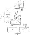
- Figure 3 is a schematic diagram that further illustrates the concept of designing or building an air separation unit according to the present invention.
- the design method involves selecting specific modules from various libraries, e.g., L1, L2 and L3, each comprising different modules or component designs.
- library L1 comprises modules M1a and M1b, which correspond to two different versions or designs of a module that performs a particular function.
- library L2 comprises modules M2a, M2b and M2c, which are different designs of another module.
- modules within each library differ from each other primarily by the module size or capacity, although in some cases, they may differ by performance efficiency.
- each module within the same library is characterized by at least three interface points for coupling to one or more modules from other libraries.
- at least some of the interface points should have the same spatial layout as every other module in that library, regardless of the module design or size.
- modules M2a, M2b and M2c may have different gas flow capacities and/or physical sizes, each of these modules has the same topography for at least one or more subsets of interface points.
- interface points (321b, 323b, 325b) on module M2b have the same spatial relationship as interface points (321c, 323c, 325c) on module M2c - e.g., relative spatial coordinates d1 and d2 being the same, and likewise for the corresponding interface points on module M2a.
- each module in library L2 can readily be coupled to corresponding interface points (311a, 313a, 315a) on module M1a; or those on module M1b, which also has the same topography of corresponding interface points as module M1a.
- interface points (327b, 329b) of module M2b be the same as that of corresponding interface points on modules M2a and M2c, in order to facilitate the coupling of these modules to any of the modules in library L3.
- the subset (321b, 323b, 325b) be maintained in a fixed spatial relationship with respect to the subset (327b, 329b). Since modules M2b and M2c may differ in their physical dimensions, it is possible that spacings between two subsets of interface points be different from module to module within the same library.
- each module in a given library is designed such that fixed relative spatial coordinates are maintained among at least a majority of interface points within individual subsets that couple to corresponding interface points of other modules.
- the fixed relative spatial coordinates i.e., same topography or layout of interface points
- a certain amount of tolerance such as that within a predetermined range of spatial coordinates, is acceptable for the purpose of practicing the invention.
- the amount of tolerance or misalignment may vary for different modules according to specific coupling requirements and space constraints.
- the column modules in particular, can essentially employ a common pipework design.
- the tolerance of the interface points should not be so large as to make the design principle difficult or impossible to implement.
- each module is designed to have at least a majority, and preferably all, of the key interface points (e.g., pipe ends used for connecting to the other closed-coupled module) connect directly or through relatively straight and short connectors to corresponding interface points of the other module or equipment.
- the expander modules are designed for close coupling with the main heat exchanger modules (any size).
- the main heat exchanger modules are designed for close coupling with the high pressure column modules (any size).
- the interfacial connect points of modules designed for close coupling are the same despite the size differences within a module library, and this allows easy plug-in/plug-out connections to the adjoining module.
- the high pressure column and low pressure column modules are designed for close coupling with one another as are the low pressure column and argon columns.
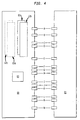
- FIG 4 is a schematic diagram showing a two-core or four-core MHE module 60 in combination with HPC module 61.
- the two-core MHE module comprises main heat exchangers 62a-b (the four-core MHE comprises exchangers 62a-d with exchangers 62c-d shown in phantom format) and subcooler 63 for the main heat transfer requirements for the air separation plant.
- This module transfers heat from the incoming main air, turbine air and boosted air streams to the exiting product oxygen, product nitrogen and waste nitrogen streams.
- MHE module 60 connects to HPC module 61 via interface connections A-N as illustrated in Table 1.
- Table 1 This table provides some examples of the interconnectivity between the high pressure column module and the heat exchange module in an air separation plant. These interface connections are also shown in Figure 1 with the labels enclosed in triangles. (Note that Figure 1 is meant to illustrate generally the fluid stream flows, but not the actual pipework connections between the modules.)
- Some of the components listed in Table 1 are conduits through a module to provide a fluid to a downstream module.
- the HPC module component is the conduit pipework and valve that transmits the poor liquid from the MHE module to the LPC module.
- both the two-core and four-core MHE modules are members of the same MHE module library, and they differ from one another principally in size.
- the interface points of both the two-core and four-core MHE modules - i.e., those used for connecting to the HPC module via connections A-N, have the same spatial relationship with the corresponding interface points of the HPC module.
- interface points corresponding to smaller pipe diameters are allowed certain degree of flexibility, it is preferable that they also maintain fixed relative spatial coordinates for each of the modules.
- the connectors that join the interface points of the MHE and HPC interface points to one another are typically a short, e.g., between about 2 and about 4 feet, relatively straight length of pipe, the ends of which mate with the corresponding interface points of the two close-coupled modules.
- These connectors are typically pipe spool pieces, and they may also include reducers, which allow coupling between pipe ends of different diameters.
- the connectors are joined to the interface points of the close-coupled modules in any convenient manner that results in a gas- and liquid-tight seal under operating conditions, e.g., welding.
- the placement or spatial relationship between the interface points on any given module may vary to design.
- the placement of the interface points relative to one another on the modules illustrated in the Figure 4 is exemplary. While the spatial relationship of the interface points on any particular module, by itself, is not critical to the practice of this invention, the spatial relationship of interface points between two modules is important, particularly those designed for close coupling.
- One goal in the placement of the interface points on two modules designed for close coupling is to maximize the total number of interface points of adjoining modules so that the points will align opposite one another, especially for interface points with a relatively large effective diameter, e.g., more than about four inches. This results in the largest number of the most linear and shortest connectors.
- interface placements are chosen with the consideration that these placements work for all modules of a given library, e.g., two-and four-core MHEs to an HPC module.
- Other considerations in determining the placement of interface points include hydraulic requirements, thermal stress, supportability, code requirements, pressure drops, thermal insulation, maintenance, minimizing leaks, minimizing costs and insulation requirements.
- the individual modules are enclosed within a frame.
- the design of the frame can vary widely, but the ultimate design is typically an amalgam of considerations relating to construction, shipping and protection.
- the frames are constructed of any material that will provide for these considerations, e.g., steel, and preferably the frames are designed to minimize their weight and space contribution to the module as a whole.
- Each module frame is designed to accommodate close coupling to another module, and typically the interface points of any given module are within the volume of the module defined by the frame.
- the selection decisions necessary to configure an optimal plant solution are of two related but different types, i.e., size-related module selections and performance-related module selections.
- different libraries may comprise different number of modules of varying ranges of size or capacity.
- the main air compressor module may require six different sizes to cover a range of plant sizes from 200-2,000 MTPD, while the booster air compressor module may require ten different sizes to cover the same range.
- not all size ranges within a library of modules are necessarily equal, e.g., of the ten booster air compressor module sizes to cover a 200-2,000 MTPD plant capacity range, one module size may cover a range twice the size of another module.
- Some module sizes will overlap with respect to matching up with a module of a given size but of another function, e.g., two or more booster air compressor modules may be available for matching with one a given main air compressor module.
- Performance related module selections are also enabled by the interchangeability of the modules, i.e., the "plug-in/plug-out" feature of the modules.
- Most performance related module selections are centered on the refrigeration system of the plant, e.g., the main heat exchange modules (more cores mean higher capital cost and lower operational power requirements) and the expander (compressor brake versus generator brake).
- Performance related process options also exist and are centered on the refrigeration system of the plant, e.g., for a high liquid oxygen co-product, use an expander flow from the booster air compressor; for a high power, no co-product solution, use an expander flow from the main air compressor.
- libraries of module designs are stored in a memory device or computer-readable medium.
- An air separation unit, or subsystems thereof may be designed by retrieving these module designs from the storage device, and selecting different modules from respective libraries. Such selection decisions may be based on constraints related to capacity, performance characteristics, process parameters, and other criteria such as power consumption and capital cost, among others.
- Such a design method may optionally be implemented on a computer.
Landscapes
- Engineering & Computer Science (AREA)
- Physics & Mathematics (AREA)
- Mechanical Engineering (AREA)
- Thermal Sciences (AREA)
- General Engineering & Computer Science (AREA)
- Health & Medical Sciences (AREA)
- Emergency Medicine (AREA)
- Separation By Low-Temperature Treatments (AREA)
- Heat-Exchange Devices With Radiators And Conduit Assemblies (AREA)
Abstract
Description
Moreover, the columns, compressors, expanders and other equipment can be arranged differently from that shown in Figure 1, depending upon the refrigeration requirements of the plant. Labels A-N represent interface connections that will be addressed in conjunction with the discussion of Figure 4.
| MHE Module and HPC Module Interface Points | |||||
| Interface Connection | Service | From | To | ||
| Module | Component | Module | Component | ||
| A | Turbine Air Stream | MHE | Main Exchanger | HPC | Turbine pipework stress loop |
| B | Gaseous Product N2 | HPC | High-pressure column | MHE | Main Exchanger |
| C | Boosted air Stream | MHE | Main Exchanger | HPC | High-pressure column |
| D | Gaseous O2 product | HPC | Liquid O2 pump module | MHE | Main exchanger |
| E | Turbine Air Stream | HPC | Turbine pipework stress loop | MHE | Pass through pipework to turbine module |
| F | Rich liquid stream | HPC | High-pressure column | MHE | Subcooler |
| G | Liquid O2 stream | HPC | High-pressure column | MHE | Subcooler |
| H | Poor liquid stream | HPC | High-pressure column | MHE | Subcooler |
| I | Poor liquid stream | MHE | Subcooler | HPC | Pass through pipework to LPC module |
| J | Liquid O2 stream | MHE | Subcooler | HPC | Pass through to pipework liquid O2 storage module |
| K | Rich Liquid stream | MHE | Subcooler | HPC | Pass through pipework to LPC module |
| L | Main Air | MHE | Main Exchanger | HPC | High-pressure column |
| M | Waste Nitrogen | HPC | Pass through pipework from LPC module | MHE | Subcooler |
| N | Expander Exhaust | MHE | Pass through pipework | HPC | High-pressure column |
Claims (8)
- A method of building an air separation plant comprising building a first module and a second module and interconnecting the first and second modules,
wherein the first module is built to a first design preselected from a first library containing at least two different designs of said first module and the second design is built to a second design preselected from a second library containing at least two different designs of said second module, wherein each of said first module designs in said first library comprises a first set of interface points with substantially the same relative spatial coordinates as every other first module design in said first library, and each of said second module designs in said second library comprises a second set of interface points with substantially the same relative spatial coordinates as every other second module design in said second library. - A method according to claim 1, wherein said first module is a high pressure column module and said second module is a main heat exchanger module or a low pressure column module.
- A method according to claim 2, wherein each of said high pressure column modules in said first library comprises a high pressure column and a reboiler-condenser.
- A method according to any one of claims 1 to 3, wherein said second module is a main heat exchanger module, and said high pressure column module is further coupled to a low pressure column module selected from a third library comprising different low pressure column module designs, each of said low pressure column module designs having a third set of interface points with substantially the same spatial coordinates as every other low pressure module design in the third library.
- An air separation unit comprising:wherein said first module is of a design selected from a first library containing at least two different designs of said first module and said second module is of a design selected from a second library containing at least two different designs of said second module, each of said first module designs in said first library having a first set of interface points with substantially the same relative spatial coordinates as every other first module design in said first library and each of said second module designs in said second library having a second set of interface points with substantially the same relative spatial coordinates as every other second module design in said second library.a first module having a first set of interface points coupled to a second set of interface points of a second module;
- An air separation unit according to claim 5, wherein said first module is a high pressure column module and said second module is a main heat exchanger module or a low pressure column module.
- An air separation unit according to claim 6, wherein each of said high pressure column modules in said first library comprises a high pressure column and a reboiler-condenser.
- An air separation unit according to any one of claims 5 to 7, wherein, said second module is a main heat exchanger module, and said high pressure column module is further coupled to a low pressure column module of a design selected from a third library comprising different low pressure column module designs, each of said low pressure column module designs having a third set of interface points with substantially the same relative spatial coordinates for coupling with said high pressure column module as every other low pressure column module design in said third library.
Applications Claiming Priority (2)
| Application Number | Priority Date | Filing Date | Title |
|---|---|---|---|
| US54232 | 2001-11-13 | ||
| US10/054,232 US6691532B2 (en) | 2001-11-13 | 2001-11-13 | Air separation units |
Publications (2)
| Publication Number | Publication Date |
|---|---|
| EP1314942A2 true EP1314942A2 (en) | 2003-05-28 |
| EP1314942A3 EP1314942A3 (en) | 2004-08-04 |
Family
ID=21989645
Family Applications (1)
| Application Number | Title | Priority Date | Filing Date |
|---|---|---|---|
| EP02257721A Ceased EP1314942A3 (en) | 2001-11-13 | 2002-11-07 | Construction of air separation units |
Country Status (2)
| Country | Link |
|---|---|
| US (1) | US6691532B2 (en) |
| EP (1) | EP1314942A3 (en) |
Cited By (2)
| Publication number | Priority date | Publication date | Assignee | Title |
|---|---|---|---|---|
| WO2007055965A3 (en) * | 2005-11-09 | 2007-07-26 | Praxair Technology Inc | Air separation plant design method |
| US7954339B2 (en) | 2003-03-31 | 2011-06-07 | Air Products & Chemicals, Inc. | Apparatus for cryogenic air distillation |
Families Citing this family (14)
| Publication number | Priority date | Publication date | Assignee | Title |
|---|---|---|---|---|
| US6910350B2 (en) * | 2002-08-08 | 2005-06-28 | Pacific Consolidated Industries, Llc | Nitrogen generator |
| US20130086941A1 (en) * | 2011-10-07 | 2013-04-11 | Henry Edward Howard | Air separation method and apparatus |
| DE102012008416A1 (en) * | 2012-04-27 | 2013-10-31 | Linde Aktiengesellschaft | Casing module for air separation plant |
| US20140075987A1 (en) | 2012-09-20 | 2014-03-20 | Fluor Technologies Corporation | Configurations and methods for ngl recovery for high nitrogen content feed gases |
| US10330382B2 (en) | 2016-05-18 | 2019-06-25 | Fluor Technologies Corporation | Systems and methods for LNG production with propane and ethane recovery |
| MX2019001888A (en) | 2016-09-09 | 2019-06-03 | Fluor Tech Corp | METHODS AND CONFIGURATION FOR GAS LIQUID PLANT READAPTATION (NGL) FOR HIGH ETHANE RECOVERY. |
| WO2019078892A1 (en) | 2017-10-20 | 2019-04-25 | Fluor Technologies Corporation | Phase implementation of natural gas liquid recovery plants |
| WO2019113575A1 (en) * | 2017-12-08 | 2019-06-13 | Schlumberger Technology Corporation | Compressed n2 for energy storage |
| US12215922B2 (en) | 2019-05-23 | 2025-02-04 | Fluor Technologies Corporation | Integrated heavy hydrocarbon and BTEX removal in LNG liquefaction for lean gases |
| US12098882B2 (en) * | 2018-12-13 | 2024-09-24 | Fluor Technologies Corporation | Heavy hydrocarbon and BTEX removal from pipeline gas to LNG liquefaction |
| CN109676367A (en) * | 2018-12-28 | 2019-04-26 | 乔治洛德方法研究和开发液化空气有限公司 | A kind of method of heat exchanger assemblies and the assembly heat exchanger assemblies |
| FR3116892B1 (en) * | 2020-12-02 | 2022-12-30 | Air Liquide | Apparatus for air separation by cryogenic distillation |
| IT202000032657A1 (en) * | 2020-12-29 | 2022-06-29 | Saipem Spa | ENERGY STORAGE AND PRODUCTION SYSTEM FOR THE STABILIZATION OF THE ELECTRICITY NETWORK |
| US12104850B2 (en) * | 2021-05-06 | 2024-10-01 | Air Products And Chemicals, Inc. | Fluid recovery process and apparatus for xenon and or krypton recovery |
Family Cites Families (12)
| Publication number | Priority date | Publication date | Assignee | Title |
|---|---|---|---|---|
| FR2692663B1 (en) | 1992-06-17 | 1994-08-19 | Air Liquide | Method for constructing a cryogenic gas separation unit, cryogenic unit, subassembly and transportable assembly for the construction of such a unit. |
| FR2706025B1 (en) * | 1993-06-03 | 1995-07-28 | Air Liquide | Air distillation installation. |
| FR2716816B1 (en) * | 1994-03-02 | 1996-05-03 | Air Liquide | Method for restarting an auxiliary argon / oxygen separation column by distillation, and corresponding installation. |
| FR2752530B1 (en) | 1996-08-21 | 1998-09-25 | Air Liquide | INSTALLATION FOR SEPARATING A GAS MIXTURE |
| US6205815B1 (en) * | 1997-04-11 | 2001-03-27 | L'air Liquide, Societe Anonyme Pour L'etude Et L'exploitation Des Procedes Georges Claude | Plant for separation of a gas mixture by distillation |
| FR2761897B1 (en) | 1997-04-11 | 1999-05-14 | Air Liquide | INSTALLATION FOR SEPARATING A GAS MIXTURE BY DISTILLATION |
| FR2769656B1 (en) | 1997-10-14 | 1999-12-17 | Air Liquide | METHOD FOR MAKING A PACKAGE BY ASSEMBLING AN INTERIOR STRUCTURE FOR CONTAINING FLUID, AN OUTSIDE STRUCTURE AND EQUIPMENT, AND METHOD FOR CONSTRUCTION ON SITE USING SUCH A PACKAGE |
| FR2775439B1 (en) | 1997-10-14 | 2000-04-14 | Air Liquide | METHOD FOR CONSTRUCTING AN INTERIOR STRUCTURE FOR CONTAINING AN ELONGATED FLUID, LARGE DIMENSIONS, AND SURROUNDED BY AN EXTERNAL STRUCTURE |
| FR2774753B1 (en) | 1998-02-06 | 2000-04-28 | Air Liquide | AIR DISTILLATION SYSTEM COMPRISING MULTIPLE CRYOGENIC DISTILLATION UNITS OF THE SAME TYPE |
| FR2774752B1 (en) | 1998-02-06 | 2000-06-16 | Air Liquide | AIR DISTILLATION SYSTEM AND CORRESPONDING COLD BOX |
| US5896755A (en) * | 1998-07-10 | 1999-04-27 | Praxair Technology, Inc. | Cryogenic rectification system with modular cold boxes |
| FR2780147B1 (en) * | 1999-06-29 | 2001-01-05 | Air Liquide | AIR DISTILLATION SYSTEM AND CORRESPONDING COLD BOX |
-
2001
- 2001-11-13 US US10/054,232 patent/US6691532B2/en not_active Expired - Fee Related
-
2002
- 2002-11-07 EP EP02257721A patent/EP1314942A3/en not_active Ceased
Cited By (2)
| Publication number | Priority date | Publication date | Assignee | Title |
|---|---|---|---|---|
| US7954339B2 (en) | 2003-03-31 | 2011-06-07 | Air Products & Chemicals, Inc. | Apparatus for cryogenic air distillation |
| WO2007055965A3 (en) * | 2005-11-09 | 2007-07-26 | Praxair Technology Inc | Air separation plant design method |
Also Published As
| Publication number | Publication date |
|---|---|
| US20030089126A1 (en) | 2003-05-15 |
| US6691532B2 (en) | 2004-02-17 |
| EP1314942A3 (en) | 2004-08-04 |
Similar Documents
| Publication | Publication Date | Title |
|---|---|---|
| US6691532B2 (en) | Air separation units | |
| Castle | Air separation and liquefaction: recent developments and prospects for the beginning of the new millennium | |
| AU741159B2 (en) | Air distillation plant and corresponding cold box | |
| US7516626B2 (en) | Apparatus for the low-temperature separation of a gas mixture, in particular air | |
| AU738523B2 (en) | Air distillation plant comprising a plurality of cryogenic distillation units of the same type | |
| US9816765B2 (en) | Piping module for air fractionation plant | |
| EP3943852B1 (en) | Liquefaction system | |
| CN104272046A (en) | Transportable package having a cold box, low-temperature air separation plant and method for producing a low-temperature air separation plant | |
| US20220364787A1 (en) | Heat exchanger for a liquefied natural gas facility | |
| CA2270507A1 (en) | Cryogenic rectification system with modular cold boxes | |
| KR100494195B1 (en) | Multiple process plant product lines from a common set of engineered components | |
| EP3374713B1 (en) | Method and system for providing supplemental refrigeration to an air separation plant | |
| CN102706097B (en) | The equipment of low temperature air separating | |
| US11709018B2 (en) | Single packaged air separation apparatus with reverse main heat exchanger | |
| CN101018996A (en) | Cryogenic system for producing elevated pressure nitrogen | |
| Castle | Fifty-years’ development of cryogenic liquefaction processes | |
| EP3674644B1 (en) | Heat exchanger assembly and method for assembling same | |
| US20150052942A1 (en) | Transportable package with a cold box, and method for producing a low-temperature air separation system | |
| CN223435369U (en) | Rectifying column system | |
| EP4560235A1 (en) | Heat exchanger | |
| KR20240054183A (en) | Process and apparatus for improved recovery of argon | |
| Bourguet | Cryogenic Technology and Scaleup Problems of Very Large LNG Plants |
Legal Events
| Date | Code | Title | Description |
|---|---|---|---|
| PUAI | Public reference made under article 153(3) epc to a published international application that has entered the european phase |
Free format text: ORIGINAL CODE: 0009012 |
|
| AK | Designated contracting states |
Designated state(s): AT BE BG CH CY CZ DE DK EE ES FI FR GB GR IE IT LI LU MC NL PT SE SK TR |
|
| AX | Request for extension of the european patent |
Extension state: AL LT LV MK RO SI |
|
| PUAL | Search report despatched |
Free format text: ORIGINAL CODE: 0009013 |
|
| AK | Designated contracting states |
Kind code of ref document: A3 Designated state(s): AT BE BG CH CY CZ DE DK EE ES FI FR GB GR IE IT LI LU MC NL PT SE SK TR |
|
| AX | Request for extension of the european patent |
Extension state: AL LT LV MK RO SI |
|
| 17P | Request for examination filed |
Effective date: 20041207 |
|
| AKX | Designation fees paid |
Designated state(s): AT BE BG CH CY CZ DE DK EE ES FI FR GB GR IE IT LI LU MC NL PT SE SK TR |
|
| STAA | Information on the status of an ep patent application or granted ep patent |
Free format text: STATUS: THE APPLICATION HAS BEEN REFUSED |
|
| 18R | Application refused |
Effective date: 20070628 |