EP1314606A2 - Filler neck for a fuel system - Google Patents
Filler neck for a fuel system Download PDFInfo
- Publication number
- EP1314606A2 EP1314606A2 EP02255325A EP02255325A EP1314606A2 EP 1314606 A2 EP1314606 A2 EP 1314606A2 EP 02255325 A EP02255325 A EP 02255325A EP 02255325 A EP02255325 A EP 02255325A EP 1314606 A2 EP1314606 A2 EP 1314606A2
- Authority
- EP
- European Patent Office
- Prior art keywords
- fuel
- filler neck
- shuttle
- coupled
- outlet aperture
- Prior art date
- Legal status (The legal status is an assumption and is not a legal conclusion. Google has not performed a legal analysis and makes no representation as to the accuracy of the status listed.)
- Withdrawn
Links
- 239000000446 fuel Substances 0.000 title claims abstract description 64
- 239000000945 filler Substances 0.000 title claims abstract description 40
- 239000002828 fuel tank Substances 0.000 claims abstract description 17
- 239000007788 liquid Substances 0.000 claims description 29
- 239000000203 mixture Substances 0.000 claims description 3
- 210000003739 neck Anatomy 0.000 description 22
- 230000008878 coupling Effects 0.000 description 1
- 238000010168 coupling process Methods 0.000 description 1
- 238000005859 coupling reaction Methods 0.000 description 1
- 238000010586 diagram Methods 0.000 description 1
- 230000003014 reinforcing effect Effects 0.000 description 1
Images


Classifications
-
- B—PERFORMING OPERATIONS; TRANSPORTING
- B60—VEHICLES IN GENERAL
- B60K—ARRANGEMENT OR MOUNTING OF PROPULSION UNITS OR OF TRANSMISSIONS IN VEHICLES; ARRANGEMENT OR MOUNTING OF PLURAL DIVERSE PRIME-MOVERS IN VEHICLES; AUXILIARY DRIVES FOR VEHICLES; INSTRUMENTATION OR DASHBOARDS FOR VEHICLES; ARRANGEMENTS IN CONNECTION WITH COOLING, AIR INTAKE, GAS EXHAUST OR FUEL SUPPLY OF PROPULSION UNITS IN VEHICLES
- B60K15/00—Arrangement in connection with fuel supply of combustion engines or other fuel consuming energy converters, e.g. fuel cells; Mounting or construction of fuel tanks
- B60K15/03—Fuel tanks
- B60K15/04—Tank inlets
Definitions
- the present disclosure relates to a fuel system for a vehicle, more particularly, to a filler neck for introducing fuel from a pump nozzle into a vehicle fuel tank.
- a filler neck is adapted for use with a fuel-delivery conduit.
- the fuel-delivery conduit defines an axis disposed transversely to an axis of the filler neck and is adapted to be coupled to a fuel tank inlet of a vehicle fuel tank.
- the filler neck comprises a housing and a shuttle.
- the housing is adapted to be coupled to the fuel-delivery conduit and includes a passageway that defines the axis of the filler neck and is adapted to receive a pump nozzle.
- the shuttle is positioned for movement in the passageway along the axis of the filler neck between a closed position to close the passageway and an opened position to open the passageway in response to engagement with the pump nozzle.
- the shuttle includes a side wall and a guide surface.
- the side wall defines an outlet aperture adapted for communication with the fuel-delivery conduit when the shuttle is positioned in the opened position.
- the guide surface is positioned to direct liquid fuel dispensed by the pump nozzle through the outlet aperture into the fuel-delivery conduit when the shuttle is positioned in the opened position. This arrangement promotes economy of space in the vehicle.
- the side wall of the shuttle includes a first half and a second half which are defined by a first plane on which the axis of the filler neck lies.
- the first half defines an outlet aperture through which liquid fuel dispensed by the pump nozzle flows into the fuel-delivery conduit in a direction transverse to the axis when the shuttle is positioned in the opened position.
- the second half is apertureless so that liquid fuel dispensed by the pump nozzle flows through the outlet aperture.
- the filler neck, the fuel-delivery conduit, and the vehicle fuel tank are part of a fuel system which also includes a fuel vapor re-circulation conduit coupled to the vehicle fuel tank.
- the housing of the filler neck defines a nozzle-receiving chamber adapted to receive a pump nozzle, a mixing chamber, and an aperture positioned in communication with the nozzle-receiving chamber and the mixing chamber.
- the housing is adapted to position the mixing chamber in communication with the fuel-delivery conduit and the fuel vapor re-circulation conduit.
- the shuttle is positioned for movement in the aperture between a closed position to close the aperture and an opened position to open the aperture in response to engagement with the pump nozzle.
- the outlet aperture of the shuttle is positioned in the nozzle-receiving chamber when the shuttle is positioned in the closed position.
- the outlet aperture is positioned in the mixing chamber when the shuttle is positioned in the opened position so that liquid fuel dispensed by the pump nozzle can flow through the outlet aperture into the mixing chamber to mix with fuel vapor from the fuel vapor re-circulation conduit to provide a mixture of liquid fuel and fuel vapor for delivery through the fuel-delivery conduit to the vehicle fuel tank.
- a filler neck 10 of a fuel system 12 is adapted to be coupled to a fuel-delivery conduit 14 for delivery of liquid fuel from a pump nozzle 16 to a vehicle fuel tank 20 of a vehicle, as illustrated, for example, in Figs. 1-4.
- Filler neck 10 is also adapted to be coupled to a fuel vapor re-circulation conduit 22 coupled to fuel tank 20.
- Filler neck 10 is capless in that it is without a removable outer fuel cap typically used to close some types of filler necks
- Filler neck 10 includes a shuttle 26 positioned for movement along an axis 27 in a passageway 28 defined by a filler neck housing 30 between a closed position to close passageway 28 (Fig. 3) and an opened position to open passageway 28 (Fig. 4) in response to engagement with pump nozzle 16.
- a spring 31 of filler neck 10 biases shuttle 26 to its closed position.
- Shuttle 26 includes a side wall 32 and a guide surface 34 coupled to side wall 32.
- Guide surface 34 is arranged to direct liquid fuel dispensed by pump nozzle 16 through an outlet aperture 36 defined by side wall 32 into an inlet portion 35 of fuel-delivery conduit 14.
- An axis 37 defined by inlet portion 35 is positioned non-parallel or transversely to axis 27. This arrangement promotes economy of space in the vehicle because it allows fuel system 12 to make a turn nearly immediately after liquid fuel is dispensed by pump nozzle 16 into fuel system 12.
- Housing 30 includes a cover 38, a door 39, a guide 40, a sleeve 41, and a connector 42, as illustrated, for example, in Figs. 2-4.
- Door 39 is mounted to guide 40.
- Cover 38, guide 40, and sleeve 41 cooperate to define a nozzle-receiving chamber 43.
- Guide 40 is positioned within sleeve 41 and is configured to guide pump nozzle 16 into engagement with shuttle 26.
- Guide 40 is also configured to guide shuttle 16 as it moves along axis 27.
- Connector 42 is coupled to sleeve 41 and is adapted to be coupled to fuel-delivery conduit 14 and fuel vapor re-circulation conduit 22.
- a valve 30 seat 44 is positioned in contact with sleeve 41 and connector 42 for engagement with shuttle 26.
- valve seat 44 is a gasket.
- Valve seat 44 and a radially inwardly extending flange 45 of sleeve 41 cooperate to define a shuttle-receiving aperture 46 through which shuttle 26 moves along axis 27.
- Door 39 is hinged to a pair of posts 47 by a pin 48 (Fig. 2).
- Door 39 includes a gasket 50 positioned to seal against an edge defining a first nozzle receiving aperture 52 when door 39 is closed.
- a torsion spring (not shown) biases door 39 toward its closed position.
- Cover 38 includes a plurality of coupling flanges 54 arranged to slide through corresponding grooves 56 defined between bosses 57 to snap into engagement with a surface 58 to couple cover 38 to guide 40.
- Guide 40 includes an axially outer, frusto-conically-shaped portion 60 and an axially inner portion 62 coupled to portion 60, as illustrated, for example, in Figs. 2-4.
- Portion 60 includes a nozzle-guiding surface 64 leading to a second nozzle receiving aperture 65.
- Portion 62 is configured to guide shuttle 26 along axis 27.
- Portion 62 includes, in order of increasing diameter, an axially outer side wall 66, an axially intermediate side wall 68, and an axially inner side wall 70, as illustrated, for example, in Figs. 2-4.
- An annular, first connector wall 72 is coupled to outer side wall 66 and intermediate side wall 68.
- First connector wall 72 includes a slightly inclined finger-engaging surface 76.
- An annular, second connector wall 74 is coupled to intermediate side wall 68 and inner side wall 70.
- a plurality of reinforcing ribs 78 are coupled to connector walls 72, 74 and intermediate side wall 68.
- Inner side wall 70 defines two diametrically opposite pairs of rail-receiving grooves (not shown), which are discussed in more detail below.
- Connector 42 includes a sleeve portion 82, a mixing chamber portion 84, a fuel-delivery conduit connector 86, and a fuel vapor re-circulation conduit connector 88, as illustrated, for example, in Figs. 2-4.
- Sleeve portion 82 is coupled to and surrounds sleeve 41.
- Mixing chamber portion 84 cooperates with valve seat 44 to define a mixing chamber 90.
- Connector 86 is adapted to be coupled to fuel-delivery conduit 14.
- Connector 88 is adapted to be coupled to fuel vapor re-circulation conduit 22.
- Connector 88 defines an inlet 92 through which fuel vapor can flow from fuel vapor re-circulation conduit 22 into mixing chamber 90 to mix with liquid fuel dispensed by pump nozzle 16.
- Connector 86 defines an outlet 94 through which a mixture of liquid fuel and fuel vapor can flow from mixing chamber 90 to fuel delivery conduit 14.
- Shuttle 26 includes an upper portion 96 and a lower portion 98 coupled to upper portion 96 via a bayonet-style connection, as illustrated, for example, in Figs.2-4.
- upper portion includes a pair of bosses 100
- lower portion 98 includes a pair of L-shaped grooves 110 (Fig. 2).
- Each groove 110 is sized to receive respective boss 100 to couple portions 96, 98 to one another.
- Upper portion 96 includes a radially inner side wall 112, a radially outer side wall 114, and an annular connector wall 116 coupled to side walls 112, 114, as illustrated, for example, in Figs. 2-4.
- One end of spring 31 abuts flange 45 while the other end of spring 31 abuts connector wall 116 within a spring-receiving cavity 118 defined by walls 112, 114, 116.
- Bosses 100 are coupled to an inner surface of inner side wall 112.
- Upper portion 96 further includes a plurality of fingers 118, as illustrated, for example, in Figs. 2-4. Each finger 118 is cantilevered to connector wall 116 at an axially inner end of finger 118. Finger 118 includes a nozzle-engaging boss 120 positioned at an axially outer end of finger 118. Illustratively, upper portion 96 has four such fingers 118.
- Upper portion 96 also includes two diametrically opposite pairs of rails 122 coupled to an outer surface of outer side wall 114, as illustrated for example, in Figs. 2. Rails 122 are configured to slide within the rail-receiving grooves to prevent shuttle 26 from rotating about axis 27 as shuttle 26 moves along axis 27.
- Lower portion 98 includes side wall 32, a guide wall 126, and a seat engaging flange 128, as illustrated, for example, in Figs. 2-4.
- Side wall 32 defines outlet aperture 36.
- An outer surface of side wall 32 defines grooves 110 for bosses 100.
- Guide wall 126 is coupled to side wall 32 and includes guide surface 34 positioned in communication with outlet aperture 36.
- Side walls 112, 32 and guide surface 34 cooperate to define a shuttle passage 132 through which liquid fuel dispensed by pump nozzle 16 can flow.
- Guide wall 126 plugs an end of side wall 32 so that liquid fuel is directed out of shuttle passage 132 through outlet aperture 36.
- Seat-engaging flange 128 is coupled to and extends radially outwardly from side wall 32 to engage valve seat 44 when shuttle 26 is positioned in its closed position.
- Side wall 32 includes a first half 134 and a second half 136, as illustrated, for example, in Figs. 3 and 4.
- a plane on which axis 27 lies and which is orthogonal to a plane defining the cross-section of Figs. 3 and 4 defines first half 134 and second half 136.
- First half 134 defines outlet aperture 36.
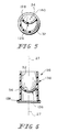
- Second half illustrated, for example, in Fig. 6, is apertureless so that all liquid fuel dispensed by pump nozzle 16 is directed through outlet aperture 36.
- Outlet aperture 36 is defined by a first curved edge 138 and a second curved edge 140 coupled to first curved edge 138, as illustrated, for example, in Figs.2-4.
- Edge 138 lies on a plane that is orthogonal to axis 27.
- Edge 140 is generally U-shaped (which includes a parabolic shape).
- Each edge 138, 140 includes a first end and a second end. The first ends are coupled to one another. The second ends are coupled to one another.
- Guide surface 34 is concave in three planes that are orthogonal to one another. These three planes define three cross-sections of guide surface 34.
- Axis 27 lies on the first and second planes and is orthogonal to the third plane.
- the first plane defines the cross-section illustrated in Figs.
- the second plane is the plane that defines first and second halves 134, 136 and defines the cross-section illustrated in Fig. 6 including a second concave guide surface cross-section.
- the third plane defines the cross-section of Fig. 5 including a third concave guide surface cross-section.
- shuttle 26 In its closed position, shuttle 26 is arranged to prevent liquid fuel from entering fuel tank 20 through housing passageway 28.
- Spring 31 biases seat-engaging flange 128 into engagement with valve seat 44 so that outlet aperture 36 is positioned in nozzle-receiving chamber 43.
- Fingers 118 are surrounded by outer and intermediate side walls 66, 68 of guide 40.
- Shuttle 26 is moved from its closed position to its opened position against the bias of spring 31 in response to engagement with pump nozzle 16 with shuttle 26.
- Pump nozzle 16 is inserted through first nozzle-receiving aperture 52 past door 39.
- Nozzle-guiding surface 64 guides pump nozzle 16 through second nozzle receiving aperture 65 into engagement with nozzle-engaging bosses 120 of fingers 118.
- bosses 120 slide against outer side wall 66 until the axially outer ends of fingers 118 reach finger-engaging surface 76. Further engagement of pump nozzle 16 with bosses 120 causes fingers 118 to flare radially outwardly along finger-engaging surface 76 into engagement with intermediate side wall 68.
- Pump nozzle 16 then slides past bosses 120 until pump nozzle 16 engages an axially outer end of side wall 32 of lower portion 98.
- Shuttle 26 remains in its opened position so long as pump nozzle 16 remains in the space between bosses 120. Once pump nozzle 16 is withdrawn from that space, spring 31 causes the axially outer ends of fingers 118 to slide radially inwardly toward one another against finger-engaging surface 76 and urges shuttle 26 back to its closed position. Rails 122 slide in the rail-receiving grooves to prevent shuttle 26 from rotating about axis 27 as shuttle 26 moves between its closed and opened positions.
- liquid fuel dispensed by pump nozzle 16 flows past guide surface 34 through outlet aperture 36 and outlet 94 into fuel-delivery conduit 14.
- Guide surface 34 is curved to turn the dispensed liquid fuel smoothly from a first direction generally parallel to axis 27 to a second direction transverse to the first direction.
- Guide surface 34 directs all the liquid fuel through outlet aperture 36.
- Outlet aperture 36 faces toward outlet 94 so that the dispensed liquid fuel flows directly through outlet 94 into inlet portion 35 of fuel-delivery conduit 14.
- fuel system 12 is configured to change the direction of flow of liquid fuel dispensed by pump nozzle 16 nearly immediately after liquid fuel is dispensed into fuel system 12 to promote economy of space in the vehicle.
- Outlet aperture 36 faces away from inlet 92 so that, as liquid fuel flows through outlet aperture 36 and outlet 94, fuel vapor is drawn from fuel tank 20 through inlet 92 into mixing chamber 90 to mix with liquid fuel for delivery back to fuel tank 20.
- This arrangement causes liquid fuel to mix with fuel vapor, rather than air, to reduce the volatility of the fuel.
Landscapes
- Engineering & Computer Science (AREA)
- Life Sciences & Earth Sciences (AREA)
- Sustainable Development (AREA)
- Sustainable Energy (AREA)
- Chemical & Material Sciences (AREA)
- Combustion & Propulsion (AREA)
- Transportation (AREA)
- Mechanical Engineering (AREA)
- Cooling, Air Intake And Gas Exhaust, And Fuel Tank Arrangements In Propulsion Units (AREA)
Abstract
Description
- The present disclosure relates to a fuel system for a vehicle, more particularly, to a filler neck for introducing fuel from a pump nozzle into a vehicle fuel tank.
- Filler necks for fuel systems are known. See, for example, U.S. Patent Nos.: 5,056,570; 5,271,438; 5,730,194; 5,732,840; 6,056,029; and 6,189,581B1.
- According to the present disclosure, a filler neck is adapted for use with a fuel-delivery conduit. The fuel-delivery conduit defines an axis disposed transversely to an axis of the filler neck and is adapted to be coupled to a fuel tank inlet of a vehicle fuel tank. The filler neck comprises a housing and a shuttle. The housing is adapted to be coupled to the fuel-delivery conduit and includes a passageway that defines the axis of the filler neck and is adapted to receive a pump nozzle. The shuttle is positioned for movement in the passageway along the axis of the filler neck between a closed position to close the passageway and an opened position to open the passageway in response to engagement with the pump nozzle. The shuttle includes a side wall and a guide surface. The side wall defines an outlet aperture adapted for communication with the fuel-delivery conduit when the shuttle is positioned in the opened position. The guide surface is positioned to direct liquid fuel dispensed by the pump nozzle through the outlet aperture into the fuel-delivery conduit when the shuttle is positioned in the opened position. This arrangement promotes economy of space in the vehicle.
- Illustratively, the side wall of the shuttle includes a first half and a second half which are defined by a first plane on which the axis of the filler neck lies. The first half defines an outlet aperture through which liquid fuel dispensed by the pump nozzle flows into the fuel-delivery conduit in a direction transverse to the axis when the shuttle is positioned in the opened position. The second half is apertureless so that liquid fuel dispensed by the pump nozzle flows through the outlet aperture.
- Illustratively, the filler neck, the fuel-delivery conduit, and the vehicle fuel tank are part of a fuel system which also includes a fuel vapor re-circulation conduit coupled to the vehicle fuel tank. The housing of the filler neck defines a nozzle-receiving chamber adapted to receive a pump nozzle, a mixing chamber, and an aperture positioned in communication with the nozzle-receiving chamber and the mixing chamber. The housing is adapted to position the mixing chamber in communication with the fuel-delivery conduit and the fuel vapor re-circulation conduit.
- The shuttle is positioned for movement in the aperture between a closed position to close the aperture and an opened position to open the aperture in response to engagement with the pump nozzle. The outlet aperture of the shuttle is positioned in the nozzle-receiving chamber when the shuttle is positioned in the closed position. The outlet aperture is positioned in the mixing chamber when the shuttle is positioned in the opened position so that liquid fuel dispensed by the pump nozzle can flow through the outlet aperture into the mixing chamber to mix with fuel vapor from the fuel vapor re-circulation conduit to provide a mixture of liquid fuel and fuel vapor for delivery through the fuel-delivery conduit to the vehicle fuel tank.
- Additional features will become apparent to those skilled in the art upon consideration of the following detailed description of illustrative embodiments exemplifying the best mode as presently perceived.
- The detailed description particularly refers to the accompanying figures in which:
- Fig. 1 is a block diagram showing a filler neck adapted to receive a pump nozzle and to be coupled to a fuel-delivery conduit and a fuel vapor re-circulation conduit which are coupled to a vehicle fuel tank;
- Fig. 2 is an exploded perspective view of the filler neck of Fig. 1;
- Fig. 3 is a longitudinal sectional view of the filler neck of Fig. 1 showing the filler neck including a housing and a shuttle positioned in a closed position to close a passageway of the housing;
- Fig. 4 is a longitudinal sectional view of the filler neck similar to Fig. 2 showing the shuttle positioned in an opened position to open the passageway of the housing;
- Fig. 5 is a transverse sectional view of a lower portion of the shuttle as viewed in a direction suggested by line 5-5 of Fig. 4; and
- Fig. 6 is a longitudinal sectional view of the lower portion of the shuttle as viewed in a direction suggested by line 6-6 of Fig. 4.
-
- A
filler neck 10 of afuel system 12 is adapted to be coupled to a fuel-delivery conduit 14 for delivery of liquid fuel from apump nozzle 16 to avehicle fuel tank 20 of a vehicle, as illustrated, for example, in Figs. 1-4.Filler neck 10 is also adapted to be coupled to a fuelvapor re-circulation conduit 22 coupled tofuel tank 20.Filler neck 10 is capless in that it is without a removable outer fuel cap typically used to close some types of filler necks -
Filler neck 10 includes ashuttle 26 positioned for movement along anaxis 27 in apassageway 28 defined by afiller neck housing 30 between a closed position to close passageway 28 (Fig. 3) and an opened position to open passageway 28 (Fig. 4) in response to engagement withpump nozzle 16. Aspring 31 offiller neck 10biases shuttle 26 to its closed position. Shuttle 26 includes aside wall 32 and aguide surface 34 coupled toside wall 32. -
Guide surface 34 is arranged to direct liquid fuel dispensed bypump nozzle 16 through anoutlet aperture 36 defined byside wall 32 into aninlet portion 35 of fuel-delivery conduit 14. Anaxis 37 defined byinlet portion 35 is positioned non-parallel or transversely toaxis 27. This arrangement promotes economy of space in the vehicle because it allowsfuel system 12 to make a turn nearly immediately after liquid fuel is dispensed bypump nozzle 16 intofuel system 12. -
Housing 30 includes acover 38, adoor 39, aguide 40, asleeve 41, and aconnector 42, as illustrated, for example, in Figs. 2-4. Door 39 is mounted toguide 40.Cover 38,guide 40, andsleeve 41 cooperate to define a nozzle-receivingchamber 43.Guide 40 is positioned withinsleeve 41 and is configured to guidepump nozzle 16 into engagement withshuttle 26.Guide 40 is also configured to guideshuttle 16 as it moves alongaxis 27.Connector 42 is coupled tosleeve 41 and is adapted to be coupled to fuel-delivery conduit 14 and fuelvapor re-circulation conduit 22. Avalve 30seat 44 is positioned in contact withsleeve 41 andconnector 42 for engagement withshuttle 26. Illustratively,valve seat 44 is a gasket.Valve seat 44 and a radially inwardly extendingflange 45 ofsleeve 41 cooperate to define a shuttle-receivingaperture 46 through whichshuttle 26 moves alongaxis 27. -
Door 39 is hinged to a pair ofposts 47 by a pin 48 (Fig. 2).Door 39 includes agasket 50 positioned to seal against an edge defining a firstnozzle receiving aperture 52 whendoor 39 is closed. A torsion spring (not shown) biasesdoor 39 toward its closed position.Cover 38 includes a plurality ofcoupling flanges 54 arranged to slide throughcorresponding grooves 56 defined betweenbosses 57 to snap into engagement with asurface 58 tocouple cover 38 to guide 40. -
Guide 40 includes an axially outer, frusto-conically-shaped portion 60 and an axiallyinner portion 62 coupled toportion 60, as illustrated, for example, in Figs. 2-4.Portion 60 includes a nozzle-guidingsurface 64 leading to a secondnozzle receiving aperture 65. -
Portion 62 is configured to guideshuttle 26 alongaxis 27.Portion 62 includes, in order of increasing diameter, an axiallyouter side wall 66, an axiallyintermediate side wall 68, and an axiallyinner side wall 70, as illustrated, for example, in Figs. 2-4. An annular,first connector wall 72 is coupled toouter side wall 66 andintermediate side wall 68.First connector wall 72 includes a slightly inclined finger-engaging surface 76. An annular,second connector wall 74 is coupled tointermediate side wall 68 andinner side wall 70. A plurality of reinforcingribs 78 are coupled toconnector walls intermediate side wall 68.Inner side wall 70 defines two diametrically opposite pairs of rail-receiving grooves (not shown), which are discussed in more detail below. -
Connector 42 includes asleeve portion 82, amixing chamber portion 84, a fuel-delivery conduit connector 86, and a fuel vaporre-circulation conduit connector 88, as illustrated, for example, in Figs. 2-4.Sleeve portion 82 is coupled to and surroundssleeve 41.Mixing chamber portion 84 cooperates withvalve seat 44 to define amixing chamber 90.Connector 86 is adapted to be coupled to fuel-delivery conduit 14.Connector 88 is adapted to be coupled to fuelvapor re-circulation conduit 22.Connector 88 defines aninlet 92 through which fuel vapor can flow from fuelvapor re-circulation conduit 22 into mixingchamber 90 to mix with liquid fuel dispensed bypump nozzle 16.Connector 86 defines anoutlet 94 through which a mixture of liquid fuel and fuel vapor can flow from mixingchamber 90 tofuel delivery conduit 14. -
Shuttle 26 includes anupper portion 96 and alower portion 98 coupled toupper portion 96 via a bayonet-style connection, as illustrated, for example, in Figs.2-4. Illustratively, upper portion includes a pair ofbosses 100 andlower portion 98 includes a pair of L-shaped grooves 110 (Fig. 2). Eachgroove 110 is sized to receiverespective boss 100 to coupleportions -
Upper portion 96 includes a radiallyinner side wall 112, a radiallyouter side wall 114, and anannular connector wall 116 coupled toside walls spring 31 abutsflange 45 while the other end ofspring 31 abutsconnector wall 116 within a spring-receivingcavity 118 defined bywalls Bosses 100 are coupled to an inner surface ofinner side wall 112. -
Upper portion 96 further includes a plurality offingers 118, as illustrated, for example, in Figs. 2-4. Eachfinger 118 is cantilevered toconnector wall 116 at an axially inner end offinger 118.Finger 118 includes a nozzle-engagingboss 120 positioned at an axially outer end offinger 118. Illustratively,upper portion 96 has foursuch fingers 118. -
Upper portion 96 also includes two diametrically opposite pairs ofrails 122 coupled to an outer surface ofouter side wall 114, as illustrated for example, in Figs. 2.Rails 122 are configured to slide within the rail-receiving grooves to preventshuttle 26 from rotating aboutaxis 27 asshuttle 26 moves alongaxis 27. -
Lower portion 98 includesside wall 32, aguide wall 126, and aseat engaging flange 128, as illustrated, for example, in Figs. 2-4.Side wall 32 definesoutlet aperture 36. An outer surface ofside wall 32 definesgrooves 110 forbosses 100.Guide wall 126 is coupled toside wall 32 and includesguide surface 34 positioned in communication withoutlet aperture 36.Side walls surface 34 cooperate to define ashuttle passage 132 through which liquid fuel dispensed bypump nozzle 16 can flow.Guide wall 126 plugs an end ofside wall 32 so that liquid fuel is directed out ofshuttle passage 132 throughoutlet aperture 36. Seat-engagingflange 128 is coupled to and extends radially outwardly fromside wall 32 to engagevalve seat 44 whenshuttle 26 is positioned in its closed position. -
Side wall 32 includes afirst half 134 and asecond half 136, as illustrated, for example, in Figs. 3 and 4. A plane on whichaxis 27 lies and which is orthogonal to a plane defining the cross-section of Figs. 3 and 4 definesfirst half 134 andsecond half 136.First half 134 definesoutlet aperture 36. Second half, illustrated, for example, in Fig. 6, is apertureless so that all liquid fuel dispensed bypump nozzle 16 is directed throughoutlet aperture 36. -
Outlet aperture 36 is defined by a firstcurved edge 138 and a secondcurved edge 140 coupled to firstcurved edge 138, as illustrated, for example, in Figs.2-4.Edge 138 lies on a plane that is orthogonal toaxis 27.Edge 140 is generally U-shaped (which includes a parabolic shape). Eachedge Guide surface 34 is concave in three planes that are orthogonal to one another. These three planes define three cross-sections ofguide surface 34.Axis 27 lies on the first and second planes and is orthogonal to the third plane. Illustratively, the first plane defines the cross-section illustrated in Figs. 3 and 4 including a first concave guide surface cross-section. The second plane is the plane that defines first andsecond halves - In its closed position,
shuttle 26 is arranged to prevent liquid fuel from enteringfuel tank 20 throughhousing passageway 28.Spring 31 biases seat-engagingflange 128 into engagement withvalve seat 44 so thatoutlet aperture 36 is positioned in nozzle-receivingchamber 43.Fingers 118 are surrounded by outer andintermediate side walls guide 40. -
Shuttle 26 is moved from its closed position to its opened position against the bias ofspring 31 in response to engagement withpump nozzle 16 withshuttle 26.Pump nozzle 16 is inserted through first nozzle-receivingaperture 52past door 39. Nozzle-guidingsurface 64 guides pumpnozzle 16 through secondnozzle receiving aperture 65 into engagement with nozzle-engagingbosses 120 offingers 118. Aspump nozzle 16 is inserted further,bosses 120 slide againstouter side wall 66 until the axially outer ends offingers 118 reach finger-engagingsurface 76. Further engagement ofpump nozzle 16 withbosses 120causes fingers 118 to flare radially outwardly along finger-engagingsurface 76 into engagement withintermediate side wall 68.Pump nozzle 16 then slidespast bosses 120 untilpump nozzle 16 engages an axially outer end ofside wall 32 oflower portion 98. -
Shuttle 26 remains in its opened position so long aspump nozzle 16 remains in the space betweenbosses 120. Oncepump nozzle 16 is withdrawn from that space,spring 31 causes the axially outer ends offingers 118 to slide radially inwardly toward one another against finger-engagingsurface 76 and urges shuttle 26 back to its closed position.Rails 122 slide in the rail-receiving grooves to preventshuttle 26 from rotating aboutaxis 27 asshuttle 26 moves between its closed and opened positions. - When
shuttle 26 is positioned in its opened position, liquid fuel dispensed bypump nozzle 16 flows pastguide surface 34 throughoutlet aperture 36 andoutlet 94 into fuel-delivery conduit 14.Guide surface 34 is curved to turn the dispensed liquid fuel smoothly from a first direction generally parallel toaxis 27 to a second direction transverse to the first direction.Guide surface 34 directs all the liquid fuel throughoutlet aperture 36.Outlet aperture 36 faces towardoutlet 94 so that the dispensed liquid fuel flows directly throughoutlet 94 intoinlet portion 35 of fuel-delivery conduit 14. Thus,fuel system 12 is configured to change the direction of flow of liquid fuel dispensed bypump nozzle 16 nearly immediately after liquid fuel is dispensed intofuel system 12 to promote economy of space in the vehicle. -
Outlet aperture 36 faces away frominlet 92 so that, as liquid fuel flows throughoutlet aperture 36 andoutlet 94, fuel vapor is drawn fromfuel tank 20 throughinlet 92 into mixingchamber 90 to mix with liquid fuel for delivery back tofuel tank 20. This arrangement causes liquid fuel to mix with fuel vapor, rather than air, to reduce the volatility of the fuel.
Claims (10)
- A filler neck for use with a fuel-delivery conduit defining an axis disposed transversely to an axis of the filler neck and adapted to be coupled to a vehicle fuel tank, the filler neck comprising
a housing adapted to be coupled to the fuel-delivery conduit, the housing including a passageway that defines the axis of the filler neck and is adapted to receive a pump nozzle, and
a shuttle positioned for movement in the passageway along the axis of
the filler neck between a closed position to close the passageway and an opened position to open the passageway in response to engagement with the pump nozzle, the shuttle including a side wall and a guide surface, the side wall defining an outlet aperture adapted for communication with the fuel-delivery conduit when the shuttle is positioned in the opened position, the guide surface being positioned to direct liquid fuel dispensed by the pump nozzle through the outlet aperture into the fuel-delivery conduit when the shuttle is positioned in the opened position. - The filler neck of claim 1, wherein the guide surface includes an axially outermost portion and an axially innermost portion, the axially outermost portion is coupled to an inner surface of the side wall, and the axially innermost portion is coupled to the side wall at the outlet aperture.
- The filler neck of claim 1, wherein the guide surface is concave in three planes orthogonal to one another.
- The filler neck of claim 1, wherein the side wall includes a first half and a second half which are defined by a first plane on which the axis lies, the first half defines the outlet aperture through which liquid fuel dispensed by the pump nozzle flows into the fuel-delivery conduit in a direction transverse to the axis when the shuttle is positioned in the opened position, and the second half is apertureless so that liquid fuel dispensed by the fuel pump flows through the outlet aperture.
- The filler neck of claim 4, wherein the first half includes a first curved edge and a second curved edge coupled to the first curved edge to define the outlet aperture.
- The filler neck of claim 5, wherein the first curved edge is positioned on a second plane perpendicular to the first plane, each of the first curved edge and the second curved edge includes a first end and a second end, each of the first end and the second end of the first curved edge is coupled to one of the first end and the second end of the second curved edge.
- The filler neck of claim 6, wherein the guide surface is coupled to the second curved edge to direct liquid fuel dispensed by the pump nozzle through the outlet aperture and in the direction transverse to the axis.
- The filler neck of claim 1, wherein the housing defines a nozzle-receiving chamber adapted to receive the pump nozzle, a mixing chamber, and an aperture positioned in communication with the nozzle-receiving chamber and the mixing chamber, the housing is adapted to position the mixing chamber in communication with the fuel-delivery conduit and a fuel vapor re-circulation conduit adapted to be coupled to the housing and the vehicle fuel tank, the shuttle is positioned for movement in the aperture between the closed position to close the aperture and the opened position to open the aperture in response to engagement with the pump nozzle, the outlet aperture is positioned in the nozzle-receiving chamber when the shuttle is positioned in the closed position, the outlet aperture is positioned
in the mixing chamber when the shuttle is positioned in the opened position so that liquid fuel dispensed by the pump nozzle can flow through the outlet aperture into the mixing chamber to mix with fuel vapor from the fuel vapor re-circulation conduit to provide a mixture of liquid fuel and fuel vapor for delivery through the fuel-delivery conduit to the vehicle fuel tank. - The filler neck of claim 8, wherein the housing further defines an outlet positioned in communication with the mixing chamber and connectable with the fuel-delivery conduit, and the outlet aperture faces toward the outlet when the shuttle is positioned in the opened position.
- The filler neck of claim 9, wherein the housing further defines an inlet positioned in communication with the mixing chamber and connectable with the fuel vapor re-circulation conduit, and the outlet aperture faces away from the inlet when the shuttle is positioned in the opened position.
Applications Claiming Priority (2)
| Application Number | Priority Date | Filing Date | Title |
|---|---|---|---|
| US989149 | 2001-11-21 | ||
| US09/989,149 US6546972B1 (en) | 2001-11-21 | 2001-11-21 | Filler neck for a fuel system |
Publications (2)
| Publication Number | Publication Date |
|---|---|
| EP1314606A2 true EP1314606A2 (en) | 2003-05-28 |
| EP1314606A3 EP1314606A3 (en) | 2004-03-24 |
Family
ID=25534810
Family Applications (1)
| Application Number | Title | Priority Date | Filing Date |
|---|---|---|---|
| EP02255325A Withdrawn EP1314606A3 (en) | 2001-11-21 | 2002-07-30 | Filler neck for a fuel system |
Country Status (2)
| Country | Link |
|---|---|
| US (1) | US6546972B1 (en) |
| EP (1) | EP1314606A3 (en) |
Families Citing this family (8)
| Publication number | Priority date | Publication date | Assignee | Title |
|---|---|---|---|---|
| DE10040310C2 (en) * | 2000-08-17 | 2002-11-21 | Alfmeier Praez Ag | Level control valve |
| AT5686U1 (en) * | 2001-10-09 | 2002-10-25 | Tesma Motoren Getriebetechnik | FILLING TUBE FOR A FUEL TANK |
| US6923224B1 (en) * | 2004-01-15 | 2005-08-02 | Stant Manufacturing Inc. | Closure and vent system for capless filler neck |
| JP5005450B2 (en) * | 2007-07-13 | 2012-08-22 | 本田技研工業株式会社 | Internal structure of fuel supply pipe mouth |
| DE102008011733A1 (en) * | 2008-02-28 | 2009-09-03 | GM Global Technology Operations, Inc., Detroit | Kraftstoffbefüllvorrichtung |
| US9873322B2 (en) | 2015-09-16 | 2018-01-23 | Stant Usa Corp. | Closure assembly for fuel tank filler neck |
| JP6561893B2 (en) * | 2016-04-01 | 2019-08-21 | 豊田合成株式会社 | Fuel supply device |
| CN110809527B (en) * | 2017-07-06 | 2022-11-15 | 本田技研工业株式会社 | Fuel filler opening structure of fuel tank |
Citations (6)
| Publication number | Priority date | Publication date | Assignee | Title |
|---|---|---|---|---|
| US5056570A (en) | 1990-03-26 | 1991-10-15 | Stant Inc. | Capless vehicle refueling system |
| US5271438A (en) | 1992-06-22 | 1993-12-21 | Stant Manufacturing Inc. | Capless vehicle refueling system with moving fill passageway |
| US5730194A (en) | 1996-03-21 | 1998-03-24 | Stant Manufacturing Inc. | Capless filler neck closure system |
| US5732840A (en) | 1995-04-21 | 1998-03-31 | Stant Manufacturing Inc. | Closure assembly for a tank filler neck |
| US6056029A (en) | 1999-03-03 | 2000-05-02 | Stant Manufacturing Inc. | Fuel-Transfer system |
| US6189581B1 (en) | 1998-05-08 | 2001-02-20 | Stant Manufacturing Inc. | Filler neck closure |
Family Cites Families (1)
| Publication number | Priority date | Publication date | Assignee | Title |
|---|---|---|---|---|
| DE60027304T2 (en) * | 1999-05-17 | 2006-11-09 | Stant Manufacturing Inc., Connersville | SAFETY GASKET OF THE LOCKING ELEMENT OF A LUGBOX FOR BIG TANK |
-
2001
- 2001-11-21 US US09/989,149 patent/US6546972B1/en not_active Expired - Fee Related
-
2002
- 2002-07-30 EP EP02255325A patent/EP1314606A3/en not_active Withdrawn
Patent Citations (6)
| Publication number | Priority date | Publication date | Assignee | Title |
|---|---|---|---|---|
| US5056570A (en) | 1990-03-26 | 1991-10-15 | Stant Inc. | Capless vehicle refueling system |
| US5271438A (en) | 1992-06-22 | 1993-12-21 | Stant Manufacturing Inc. | Capless vehicle refueling system with moving fill passageway |
| US5732840A (en) | 1995-04-21 | 1998-03-31 | Stant Manufacturing Inc. | Closure assembly for a tank filler neck |
| US5730194A (en) | 1996-03-21 | 1998-03-24 | Stant Manufacturing Inc. | Capless filler neck closure system |
| US6189581B1 (en) | 1998-05-08 | 2001-02-20 | Stant Manufacturing Inc. | Filler neck closure |
| US6056029A (en) | 1999-03-03 | 2000-05-02 | Stant Manufacturing Inc. | Fuel-Transfer system |
Also Published As
| Publication number | Publication date |
|---|---|
| EP1314606A3 (en) | 2004-03-24 |
| US6546972B1 (en) | 2003-04-15 |
Similar Documents
| Publication | Publication Date | Title |
|---|---|---|
| CN105980190B (en) | capless fuel system | |
| US6546972B1 (en) | Filler neck for a fuel system | |
| US6505644B2 (en) | Dual barrel jet fuel pump assembly for a fuel tank | |
| CN104139700B (en) | The filler neck device of mistake proofing refuelling | |
| US8201595B2 (en) | Pour spout assembly with winged stop structure | |
| US6382182B1 (en) | Fuel injector adaptor for conversion of single engines to dual fuel engines | |
| US5839489A (en) | Filling adaptor for a fuel tank | |
| US11014444B2 (en) | Capless closure assembly for fuel-tank filler pipe | |
| AU2010215709A1 (en) | Safety element for a diesel fuel container to prevent adding the wrong fuel | |
| CN113365925A (en) | Vented nozzle for liquid storage container | |
| JP2004510114A (en) | Plug-and-socket plug-in connection device with outflow blocking mechanism | |
| EP3969313B1 (en) | Capless closure assembly for fuel-tank filler pipe | |
| US10675970B2 (en) | Vehicle capless refueling system | |
| US7464736B2 (en) | System and method for preventing incorrect aircraft fuel usage | |
| US10836248B2 (en) | Nozzle guide for vehicle refueling adapter | |
| CN101163606A (en) | Capless closure assembly and method for fuel tank filler neck | |
| US10800648B2 (en) | Funnel for a fuel tank filler pipe | |
| US11325462B2 (en) | Capless closure assembly for fuel-tank filler pipe | |
| CN113307216A (en) | Oil supply port | |
| US20080041492A1 (en) | Automotive fuel filling system | |
| US11597269B2 (en) | Fuel device | |
| JP2001523195A (en) | Automotive tank and flange for the tank | |
| US11142063B2 (en) | Filler neck for filling an operating substance or additive into a vehicle tank by means of a fuel pump nozzle | |
| US10569645B2 (en) | Insert for a fuel tank filler pipe | |
| KR200210580Y1 (en) | Device for supply emergency fuel |
Legal Events
| Date | Code | Title | Description |
|---|---|---|---|
| PUAI | Public reference made under article 153(3) epc to a published international application that has entered the european phase |
Free format text: ORIGINAL CODE: 0009012 |
|
| 17P | Request for examination filed |
Effective date: 20020809 |
|
| AK | Designated contracting states |
Designated state(s): AT BE BG CH CY CZ DE DK EE ES FI FR GB GR IE IT LI LU MC NL PT SE SK TR |
|
| AX | Request for extension of the european patent |
Extension state: AL LT LV MK RO SI |
|
| PUAL | Search report despatched |
Free format text: ORIGINAL CODE: 0009013 |
|
| AK | Designated contracting states |
Kind code of ref document: A3 Designated state(s): AT BE BG CH CY CZ DE DK EE ES FI FR GB GR IE IT LI LU MC NL PT SE SK TR |
|
| AX | Request for extension of the european patent |
Extension state: AL LT LV MK RO SI |
|
| AKX | Designation fees paid |
Designated state(s): DE ES FR GB IT |
|
| 17Q | First examination report despatched |
Effective date: 20041202 |
|
| GRAP | Despatch of communication of intention to grant a patent |
Free format text: ORIGINAL CODE: EPIDOSNIGR1 |
|
| STAA | Information on the status of an ep patent application or granted ep patent |
Free format text: STATUS: THE APPLICATION IS DEEMED TO BE WITHDRAWN |
|
| 18D | Application deemed to be withdrawn |
Effective date: 20080201 |