EP1314494A1 - Device for smashing sand masses and for separating a sand mold and a cast product from a flask - Google Patents
Device for smashing sand masses and for separating a sand mold and a cast product from a flask Download PDFInfo
- Publication number
- EP1314494A1 EP1314494A1 EP02026356A EP02026356A EP1314494A1 EP 1314494 A1 EP1314494 A1 EP 1314494A1 EP 02026356 A EP02026356 A EP 02026356A EP 02026356 A EP02026356 A EP 02026356A EP 1314494 A1 EP1314494 A1 EP 1314494A1
- Authority
- EP
- European Patent Office
- Prior art keywords
- sand
- smashing
- masses
- tank
- cast product
- Prior art date
- Legal status (The legal status is an assumption and is not a legal conclusion. Google has not performed a legal analysis and makes no representation as to the accuracy of the status listed.)
- Granted
Links
- 239000004576 sand Substances 0.000 title claims abstract description 146
- 239000002245 particle Substances 0.000 claims description 26
- 239000002184 metal Substances 0.000 claims description 14
- 238000007599 discharging Methods 0.000 description 3
- 230000005484 gravity Effects 0.000 description 2
- 230000004308 accommodation Effects 0.000 description 1
- 239000000919 ceramic Substances 0.000 description 1
- 239000010419 fine particle Substances 0.000 description 1
- 238000009434 installation Methods 0.000 description 1
- 238000000034 method Methods 0.000 description 1
Images
Classifications
-
- B—PERFORMING OPERATIONS; TRANSPORTING
- B22—CASTING; POWDER METALLURGY
- B22C—FOUNDRY MOULDING
- B22C5/00—Machines or devices specially designed for dressing or handling the mould material so far as specially adapted for that purpose
- B22C5/04—Machines or devices specially designed for dressing or handling the mould material so far as specially adapted for that purpose by grinding, blending, mixing, kneading, or stirring
- B22C5/0404—Stirring by using vibrations while grinding
-
- B—PERFORMING OPERATIONS; TRANSPORTING
- B02—CRUSHING, PULVERISING, OR DISINTEGRATING; PREPARATORY TREATMENT OF GRAIN FOR MILLING
- B02C—CRUSHING, PULVERISING, OR DISINTEGRATING IN GENERAL; MILLING GRAIN
- B02C17/00—Disintegrating by tumbling mills, i.e. mills having a container charged with the material to be disintegrated with or without special disintegrating members such as pebbles or balls
- B02C17/14—Mills in which the charge to be ground is turned over by movements of the container other than by rotating, e.g. by swinging, vibrating, tilting
-
- B—PERFORMING OPERATIONS; TRANSPORTING
- B02—CRUSHING, PULVERISING, OR DISINTEGRATING; PREPARATORY TREATMENT OF GRAIN FOR MILLING
- B02C—CRUSHING, PULVERISING, OR DISINTEGRATING IN GENERAL; MILLING GRAIN
- B02C17/00—Disintegrating by tumbling mills, i.e. mills having a container charged with the material to be disintegrated with or without special disintegrating members such as pebbles or balls
- B02C17/16—Mills in which a fixed container houses stirring means tumbling the charge
-
- B—PERFORMING OPERATIONS; TRANSPORTING
- B22—CASTING; POWDER METALLURGY
- B22C—FOUNDRY MOULDING
- B22C5/00—Machines or devices specially designed for dressing or handling the mould material so far as specially adapted for that purpose
- B22C5/04—Machines or devices specially designed for dressing or handling the mould material so far as specially adapted for that purpose by grinding, blending, mixing, kneading, or stirring
- B22C5/0409—Blending, mixing, kneading or stirring; Methods therefor
- B22C5/0481—Blending, mixing, kneading or stirring; Methods therefor using vibrations
-
- B—PERFORMING OPERATIONS; TRANSPORTING
- B22—CASTING; POWDER METALLURGY
- B22D—CASTING OF METALS; CASTING OF OTHER SUBSTANCES BY THE SAME PROCESSES OR DEVICES
- B22D29/00—Removing castings from moulds, not restricted to casting processes covered by a single main group; Removing cores; Handling ingots
- B22D29/02—Vibratory apparatus specially designed for shaking out flasks
-
- Y—GENERAL TAGGING OF NEW TECHNOLOGICAL DEVELOPMENTS; GENERAL TAGGING OF CROSS-SECTIONAL TECHNOLOGIES SPANNING OVER SEVERAL SECTIONS OF THE IPC; TECHNICAL SUBJECTS COVERED BY FORMER USPC CROSS-REFERENCE ART COLLECTIONS [XRACs] AND DIGESTS
- Y10—TECHNICAL SUBJECTS COVERED BY FORMER USPC
- Y10S—TECHNICAL SUBJECTS COVERED BY FORMER USPC CROSS-REFERENCE ART COLLECTIONS [XRACs] AND DIGESTS
- Y10S241/00—Solid material comminution or disintegration
- Y10S241/10—Foundry sand treatment
Definitions
- This invention relates to an apparatus for vibratingly smashing sand masses.
- JP 57-116366 U discloses a device for vibratingly smashing sand masses.
- JP 5-93650 U(JP 7-1844 Y) discloses a device for vibratingly separating a sand mold and an as-cast product from a flask by vibratingly applying forces to the sand mold and flask.
- the device of JP 57-116366 U includes a box-like sand tank, for holding sand masses, that is elastically supported.
- the sand tank is vibrated vertically or slantingly to vibrate the sand masses in the sand tank vertically or slantingly to smash them.
- the device requires large motors and therefore it becomes large and thus necessitates a large space for its installation.
- the device of JP 5-93650 U includes a hollow support dish supported by columns and having upper and lower openings and beams disposed in the upper opening for receiving a flask that holds a sand mold and an as-cast product, an accommodating portion for receiving the broken pieces of the flask and the sand mold, the accommodating portion being elastically supported under the lower opening, a vibrating device mounted on the accommodating portion for vertically vibrating the accommodation portion, and an upright frame mounted on the accommodating portion and extending through the lower opening to a level that is slightly higher than the upper surfaces of the beams, for vibratingly applying forces to the flask.
- the broken pieces of the sand mold to be discharged from the device are relatively large masses.
- more devices are required, i.e., one for smashing the sand masses into sand particles and another for transferring the sand masses to this smashing device. The combination of these devices becomes large.
- the present invention has been conceived to overcome the drawbacks of the prior-art devices discussed above.
- the purpose of the present invention is to provide a compact device that can smash sand masses into sand particles.
- Another purpose of the present invention is to provide a compact device for separating a sand mold, an as-cast product, etc., from a flask and for smashing the sand mold into sand particles.
- the device of the present invention has unbalanced-weight-type vibrating means having unbalanced weights for vibrating a mechanism (or means) by rotating the unbalanced weights, such that the vibrations of the mechanism draw a Lissajous's figure of approximately a circle.
- an apparatus for vibratingly smashing sand masses comprises a sand tank elastically supported and having therein an inner tank for holding sand masses, the inner tank being defined by a wall disposed in the sand tank apart from the inner surface of the sand tank, the wall having a plurality of apertures, and unbalanced-weight-type vibrating means having unbalanced weights for vibrating the sand tank, including the inner tank, by rotating the unbalanced weights, such that the vibrations of the sand tank draw a Lissajous's figure of approximately a circle.
- an apparatus for separating a sand mold and an as-cast product from a flask and for smashing the separated sand mold comprises a support dish mechanism fixedly supported and having an upper opening, a lower opening, an internal space extending between the upper opening and the lower opening, and a plurality of support members positioned in the upper opening, the support members having top surfaces arranged in a horizontal plane for supporting the flask that holds the sand mold, the as-cast product, any tool to assist in constructing the sand mold, and any foreign body, a separating mechanism elastically supported under the support dish mechanism and having means for smashing the sand masses of the sand mold into sand particles and for removing the as-cast product, the foreign body, and the tool, unbalanced-weight-type vibrating means mounted on the separating mechanism and having unbalanced weights for vibrating the separating mechanism by rotation thereof such that the vibrations of the separating mechanism draw a Lissajous's
- Fig. 1 shows an embodiment of the apparatus of the present invention for vibratingly smashing sand masses into sand particles.
- the apparatus includes a box-like sand tank 30 elastically supported.
- the sand tank 30 has an inner tank 33 in it.
- the inner tank 33 is defined by a wall 31 disposed in the sand tank 30 at a position spaced apart from its inner surface 30A and is centrally located in the sand tank 30 for holding sand masses.
- the wall 31 has apertures 32 in the shape of slits through which sand particles can pass into the space defined between the wall 31 and the inner surface 30A of the sand tank 33.
- the apparatus also includes unbalanced-weight-type vibrating means 34 mounted on the outer surface of the sand tank 30 at both its sides.
- the vibrating means 34 includes a pair of motors 21, 21 and two pairs of unbalanced weights (not shown), each pair being attached to one motor 21.
- the vibrating means 34 are appropriately disposed so that when the motors operate to rotate the unbalanced weights to vibrate the sand tank 30, the vibrations of the sand tank 30, including the inner tank 33, draw a Lissajous's figure of approximately a circle.
- the sand tank 30 is elastically mounted on a frame 36 through air springs 35, 35. Further, a chute 37 is disposed at a lower portion of the sand tank 30. The chute 37 is connected to a port for discharging sand particles (not shown) that is located at the lower, central part of the sand tank 33.
- the motors 21, 21 are disposed on a horizontal, common axis of rotation, with that axis of rotation passing through the center of gravity of the combination to be vibrated of the sand tank 30 and the sand masses held in the inner tank 33 of the sand tank. Further, the two pairs of unbalanced weights rotate in the same direction at the same speed. Thus, when the unbalanced weights are so rotated, they allow the sand tank 30, including the inner tank 33, to vibrate to draw a Lissajous's figure of approximately a circle and allow the sand particles to flow in a predetermined direction.
- a predetermined amount of sand masses is fed into the inner tank 30, and the motors 21, 21 are then operated to rotate all the unbalanced weights in one direction and at the same speed.
- the sand tank 1, including the inner tank 33 is vibrated to draw a Lissajous's figure of approximately a circle.
- the vibrating apparatus of the present invention has a processing performance double that of the conventional vibrating device, i.e., the performance of the motor of the apparatus of the present invention can be half that of the motor of a conventional vibrating device.
- the apparatus vibratingly applies forces to a sand mold and a flask F that holds the sand mold, which may hold an as-cast product (the cast itself and a sprue), tools to assist in constructing the sand mold such as a chiller and a core grid, and foreign bodies such as ceramic tubes, fins, cold shots, and dirt. to separate the sand mold from the flask F and then to smash the sand mold into sand particles.
- an as-cast product the cast itself and a sprue
- tools to assist in constructing the sand mold such as a chiller and a core grid
- foreign bodies such as ceramic tubes, fins, cold shots, and dirt.
- the apparatus includes a support dish mechanism 3 fixedly supported by a plurality of support columns 1, 1 and having an upper opening, a lower opening, an internal space extending between the upper opening and the lower opening, and a plurality of support members 2, 2 in the shape of square bars positioned in the upper opening, the support members 2, 2 having top surfaces arranged in a horizontal plane for supporting the flask F that holds the sand mold, which may hold the as-cast product, the tool to assist in constructing the sand mold, and the foreign body; a separating mechanism 5 elastically supported by a plurality of coil springs 4, 4 under the support dish mechanism 3 and having means for smashing sand masses of the sand mold into sand particles and for removing the as-cast product, the tool, and the foreign body; unbalanced-weight-type vibrating means 6 mounted on the separating mechanism 5 and having unbalanced weights for vibrating the separating mechanism 5 by rotation thereof such that the vibrations of the separating mechanism draw a Lissajous's figure of approximately
- the separating mechanism 5 includes a first removing means 9'for smashing the sand masses of the sand mold into sand particles and for removing the as-cast product and relatively large-sized tools to assist in constructing the sand mold and foreign bodies, and a second removing means 10 located below the first removing means 9, for removing tools to assist in constructing the sand mold or foreign bodies that have not been removed by the first removing means 9.
- the first removing means 9 has a tub-shaped body 11 and a metal mesh 13 fixed to the body 11 so that the first removing means can act as a sieve.
- the second removing means 10 has a tub-shaped body 12 attached to the bottom of the tub-shaped body 11 of the first removing means 9.
- the tub-shaped body 12 has a metal mesh 14 so that it can act as a sieve.
- the mesh size of the metal mesh 14 of the second removing means 10 is smaller than that of the metal mesh 13 of the first removing means 9. Further, as seen in Fig.
- a chute 15 and a chute 16 are disposed at the levels of the upper surfaces of the mesh 13 and mesh 14, respectively, and they are connected to discharging ports (not shown) of the mesh 13 and mesh 14, to discharge the tools, etc.. that are caught by the meshes 13. 14.
- the discharging ports are closed by stoppers, or gates, 19, 20 that can be opened and closed by downwardly-facing cylinders 17, 18.
- the unbalanced-weight-type vibrating means 6 includes a pair of vibrating motors 21, 21, each of which is provided with a pair of unbalanced weights, and which are disposed on the separating mechanism 5 near both its sides.
- the motors 21, 21 have a common axis of rotation that passes through the center of gravity of the entire vibrating device, which is elastically mounted on the coil springs 4, 4, consisting of the first and second removing means 9, 10, the upright vibrating members 7, 7, the smashing mechanism 8, the vibrating motors 21, 21, the flask F, and the sand mold in the flask, which holds the as-cast product, etc. Further, two pairs of unbalanced weights of the motors 21, 21 are rotated at the same speed in one direction.
- the unbalanced weights when they so rotate, they allow the first and second removing means 9, 10 to vibrate to draw a Lissajous's figure of approximately a circle and allow the as-cast product, the tools, and the sand particles to be transferred in a predetermined direction.
- a flask F that holds a sand mold, which holds an as-cast product, the tools, etc., is placed on the support members 2, 2, and the pair of motors 21, 21 are then operated to rotate the unbalanced weights in one direction at the same speed.
- the upright vibrating members 7, 7, the smashing mechanism 8, the first and second removing means 9, 10 of the separating mechanism 5, etc. vibrate to draw a Lissajous's figure of approximately a circle.
- the upright vibrating members 7, 7 apply vibrations to the sand mold and the flask F, wherein the vibrations have horizontal and vertical components, and the sand mold, which may include the as-cast product, the tools, and foreign bodies are separated from the flask F and drop onto the smashing mechanism 8.
- the sand mold is broken into pieces of sand masses, and these masses, the as-cast product, the tools, the foreign bodies, etc., drop onto the separating mechanism 5.
- the sand masses, the as-cast product, the tools, the foreign bodies, etc., which have dropped onto the separating mechanism 5, are stopped by the gate 19 in the first removing means 9, and hit each other there.
- the sand masses are smashed into sand particles, and the sand particles and relatively small tools and foreign bodies pass through the metal mesh 13 of the first removing means 9 and fall onto the metal mesh 14 of the second removing means 10.
- the cylinder 17 is operated to open the gate 19.
- the as-cast product, the tools, the foreign bodies, etc. that could not pass through the metal mesh 13 move on the metal mesh 13 and are discharged from the gate 19 by using the chute 15.
- the sand particles, an as-cast product, tools, foreign bodies, etc. that have dropped onto the metal mesh 14 of the second removing means 10 hit each other in a manner similar to those on the metal mesh 13 of the first removing means 9.
- the sand particles are further smashed into fine particles, and they pass through the metal mesh 14 onto the bottom plate of the second removing means 10 and are then transferred.
- the as-cast product, the tools, the foreign bodies, etc. that could not pass through the metal mesh 14 move on the metal mesh and are discharged by the chute 16.
- stoppers are used for the first and second removing means 9, 10 of the separating mechanism 5, these stoppers may be eliminated if the first and second removing means are long and can sufficiently smash the sand masses into sand particles.
Landscapes
- Engineering & Computer Science (AREA)
- Mechanical Engineering (AREA)
- Food Science & Technology (AREA)
- Molds, Cores, And Manufacturing Methods Thereof (AREA)
- Disintegrating Or Milling (AREA)
Abstract
Description
- This invention relates to an apparatus for vibratingly smashing sand masses.
- JP 57-116366 U discloses a device for vibratingly smashing sand masses. Further, JP 5-93650 U(JP 7-1844 Y) discloses a device for vibratingly separating a sand mold and an as-cast product from a flask by vibratingly applying forces to the sand mold and flask.
- The device of JP 57-116366 U includes a box-like sand tank, for holding sand masses, that is elastically supported. The sand tank is vibrated vertically or slantingly to vibrate the sand masses in the sand tank vertically or slantingly to smash them. The device requires large motors and therefore it becomes large and thus necessitates a large space for its installation.
- The device of JP 5-93650 U includes a hollow support dish supported by columns and having upper and lower openings and beams disposed in the upper opening for receiving a flask that holds a sand mold and an as-cast product, an accommodating portion for receiving the broken pieces of the flask and the sand mold, the accommodating portion being elastically supported under the lower opening, a vibrating device mounted on the accommodating portion for vertically vibrating the accommodation portion, and an upright frame mounted on the accommodating portion and extending through the lower opening to a level that is slightly higher than the upper surfaces of the beams, for vibratingly applying forces to the flask. However, in the device for vibratingly separating the sand mold from the flask, the broken pieces of the sand mold to be discharged from the device are relatively large masses. Thus, to reclaim the sand masses, more devices are required, i.e., one for smashing the sand masses into sand particles and another for transferring the sand masses to this smashing device. The combination of these devices becomes large.
- The present invention has been conceived to overcome the drawbacks of the prior-art devices discussed above.
- The purpose of the present invention is to provide a compact device that can smash sand masses into sand particles.
- Another purpose of the present invention is to provide a compact device for separating a sand mold, an as-cast product, etc., from a flask and for smashing the sand mold into sand particles.
- The device of the present invention has unbalanced-weight-type vibrating means having unbalanced weights for vibrating a mechanism (or means) by rotating the unbalanced weights, such that the vibrations of the mechanism draw a Lissajous's figure of approximately a circle.
- In one aspect of the present invention, an apparatus for vibratingly smashing sand masses is provided. It comprises a sand tank elastically supported and having therein an inner tank for holding sand masses, the inner tank being defined by a wall disposed in the sand tank apart from the inner surface of the sand tank, the wall having a plurality of apertures, and unbalanced-weight-type vibrating means having unbalanced weights for vibrating the sand tank, including the inner tank, by rotating the unbalanced weights, such that the vibrations of the sand tank draw a Lissajous's figure of approximately a circle.
- In another aspect of the present invention, an apparatus for separating a sand mold and an as-cast product from a flask and for smashing the separated sand mold is provided. The apparatus comprises a support dish mechanism fixedly supported and having an upper opening, a lower opening, an internal space extending between the upper opening and the lower opening, and a plurality of support members positioned in the upper opening, the support members having top surfaces arranged in a horizontal plane for supporting the flask that holds the sand mold, the as-cast product, any tool to assist in constructing the sand mold, and any foreign body, a separating mechanism elastically supported under the support dish mechanism and having means for smashing the sand masses of the sand mold into sand particles and for removing the as-cast product, the foreign body, and the tool, unbalanced-weight-type vibrating means mounted on the separating mechanism and having unbalanced weights for vibrating the separating mechanism by rotation thereof such that the vibrations of the separating mechanism draw a Lissajous's figure of approximately a circle, a plurality of upright members mounted on the separating mechanism and extending through the internal space of the support dish mechanism between the support members, for vibratingly applying forces to the sand mold and the flask when the separating member is vibrated by the vibrating means, and a smashing mechanism mounted on the upright members for smashing the sand mold that drops from the flask into pieces of sand masses and for allowing the sand masses to drop from the smashing mechanism to the means of the separating mechanism for smashing the sand masses into sand particles.
-
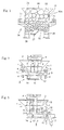
- Fig. 1 is a front view, partly in section, of the first embodiment of the apparatus of the present invention.
- Fig. 2 is a front view, partly in section, of the second embodiment of the apparatus of the present invention.
- Fig. 3 is a right side view, partly in section, of the apparatus of Fig. 2.
-
- The embodiments of the present invention are now explained by reference to the drawings.
- Fig. 1 shows an embodiment of the apparatus of the present invention for vibratingly smashing sand masses into sand particles. The apparatus includes a box-
like sand tank 30 elastically supported. Thesand tank 30 has aninner tank 33 in it. As shown in Fig. 1, theinner tank 33 is defined by awall 31 disposed in thesand tank 30 at a position spaced apart from itsinner surface 30A and is centrally located in thesand tank 30 for holding sand masses. Thewall 31 hasapertures 32 in the shape of slits through which sand particles can pass into the space defined between thewall 31 and theinner surface 30A of thesand tank 33. - The apparatus also includes unbalanced-weight-type vibrating means 34 mounted on the outer surface of the
sand tank 30 at both its sides. The vibrating means 34 includes a pair ofmotors motor 21. As will now be explained, the vibrating means 34 are appropriately disposed so that when the motors operate to rotate the unbalanced weights to vibrate thesand tank 30, the vibrations of thesand tank 30, including theinner tank 33, draw a Lissajous's figure of approximately a circle. - The
sand tank 30 is elastically mounted on aframe 36 throughair springs chute 37 is disposed at a lower portion of thesand tank 30. Thechute 37 is connected to a port for discharging sand particles (not shown) that is located at the lower, central part of thesand tank 33. - The
motors sand tank 30 and the sand masses held in theinner tank 33 of the sand tank. Further, the two pairs of unbalanced weights rotate in the same direction at the same speed. Thus, when the unbalanced weights are so rotated, they allow thesand tank 30, including theinner tank 33, to vibrate to draw a Lissajous's figure of approximately a circle and allow the sand particles to flow in a predetermined direction. - In operating the apparatus, a predetermined amount of sand masses is fed into the
inner tank 30, and themotors sand tank 1, including theinner tank 33, is vibrated to draw a Lissajous's figure of approximately a circle. - When the
sand tank 30 is so vibrated, vibrations that include two components, i.e., horizontal and vertical ones, are applied to the sand masses held in theinner tank 33. Accordingly, the sand masses are effectively smashed into sand particles, which pass through theapertures 32 and drop onto the bottom plate of the sand tank, and are then discharged from thechute 37. - For reference and comparison, the performance in smashing of the circular-vibrating apparatus of the present invention and a conventional vibrating device that produces vertical vibrations is shown in Table 1, which is attached at the end of the Description.
- As is seen from Table 1, the vibrating apparatus of the present invention has a processing performance double that of the conventional vibrating device, i.e., the performance of the motor of the apparatus of the present invention can be half that of the motor of a conventional vibrating device.
- Now the second embodiment of the apparatus of the present invention is explained by reference to Figs. 2 and 3. The apparatus vibratingly applies forces to a sand mold and a flask F that holds the sand mold, which may hold an as-cast product (the cast itself and a sprue), tools to assist in constructing the sand mold such as a chiller and a core grid, and foreign bodies such as ceramic tubes, fins, cold shots, and dirt. to separate the sand mold from the flask F and then to smash the sand mold into sand particles.
- The apparatus includes a
support dish mechanism 3 fixedly supported by a plurality ofsupport columns support members support members coil springs support dish mechanism 3 and having means for smashing sand masses of the sand mold into sand particles and for removing the as-cast product, the tool, and the foreign body; unbalanced-weight-type vibrating means 6 mounted on the separating mechanism 5 and having unbalanced weights for vibrating the separating mechanism 5 by rotation thereof such that the vibrations of the separating mechanism draw a Lissajous's figure of approximately a circle; a plurality of upright vibratingmembers support dish mechanism 3 between thesupport members members support members vibrating means 6; and a smashingmechanism 8 mounted on the upright vibratingmembers mechanism 8 to the means of the separating mechanism 5 for smashing the sand masses into sand particles. - The separating mechanism 5 includes a first removing means 9'for smashing the sand masses of the sand mold into sand particles and for removing the as-cast product and relatively large-sized tools to assist in constructing the sand mold and foreign bodies, and a
second removing means 10 located below the first removingmeans 9, for removing tools to assist in constructing the sand mold or foreign bodies that have not been removed by the first removingmeans 9. - The first removing
means 9 has a tub-shaped body 11 and ametal mesh 13 fixed to thebody 11 so that the first removing means can act as a sieve. Similarly, the second removing means 10 has a tub-shaped body 12 attached to the bottom of the tub-shaped body 11 of the first removingmeans 9. The tub-shaped body 12 has ametal mesh 14 so that it can act as a sieve. The mesh size of themetal mesh 14 of the second removing means 10 is smaller than that of themetal mesh 13 of the first removing means 9. Further, as seen in Fig. 3, achute 15 and achute 16 are disposed at the levels of the upper surfaces of themesh 13 andmesh 14, respectively, and they are connected to discharging ports (not shown) of themesh 13 andmesh 14, to discharge the tools, etc.. that are caught by themeshes 13. 14. The discharging ports are closed by stoppers, or gates, 19, 20 that can be opened and closed by downwardly-facingcylinders - The unbalanced-weight-type vibrating means 6 includes a pair of vibrating
motors motors coil springs means members mechanism 8, the vibratingmotors motors - Now the process by using the apparatus to separate the sand mold from the flask F and to smash the sand mold into sand particles and to expose the as-cast product and the tools, is explained.
- First, a flask F that holds a sand mold, which holds an as-cast product, the tools, etc., is placed on the
support members motors members mechanism 8, the first and second removingmeans - Accordingly, the upright vibrating
members mechanism 8. Thus the sand mold is broken into pieces of sand masses, and these masses, the as-cast product, the tools, the foreign bodies, etc., drop onto the separating mechanism 5. - The sand masses, the as-cast product, the tools, the foreign bodies, etc., which have dropped onto the separating mechanism 5, are stopped by the gate 19 in the first removing
means 9, and hit each other there. Thus the sand masses are smashed into sand particles, and the sand particles and relatively small tools and foreign bodies pass through themetal mesh 13 of the first removingmeans 9 and fall onto themetal mesh 14 of the second removingmeans 10. Over a predetermined time, thecylinder 17 is operated to open the gate 19. Thus the as-cast product, the tools, the foreign bodies, etc. that could not pass through themetal mesh 13 move on themetal mesh 13 and are discharged from the gate 19 by using thechute 15. - On the other hand, the sand particles, an as-cast product, tools, foreign bodies, etc. that have dropped onto the
metal mesh 14 of the second removing means 10 hit each other in a manner similar to those on themetal mesh 13 of the first removingmeans 9. Thus the sand particles are further smashed into fine particles, and they pass through themetal mesh 14 onto the bottom plate of the second removingmeans 10 and are then transferred. The as-cast product, the tools, the foreign bodies, etc. that could not pass through themetal mesh 14 move on the metal mesh and are discharged by thechute 16. - It should be understood that the embodiments described above are exemplary only, and many variations can be made to them. Thus the present invention includes such variations, and the scope of the invention is defined by the attached claims.
- For example, although in the second embodiment the stoppers (gates) are used for the first and second removing
means 
Claims (5)
- An apparatus for vibratingly smashing sand masses, comprising:a sand tank elastically supported and having therein an inner tank for holding sand masses, the inner tank being defined by a wall disposed in the sand tank apart from an inner surface of the sand tank, the wall having a plurality of apertures; andunbalanced-weight-type vibrating means having unbalanced weights for vibrating the sand tank, including the inner tank, by rotating the unbalanced weights, such that the vibrations of the sand tank draw a Lissajous's figure of approximately a circle.
- An apparatus for separating a sand mold and an as-cast product from a flask and for smashing the separated sand mold, comprising:a support dish mechanism fixedly supported and having an upper opening a lower opening, an internal space extending between the upper opening and the lower opening, and a plurality of support members positioned in the upper opening, the support members having top surfaces arranged in a horizontal plane for supporting the flask that holds the sand mold, the as-cast product, any tool to assist in constructing the sand mold, and any foreign body;a separating mechanism elastically supported under the support dish mechanism and having means for smashing sand masses of the sand mold into sand particles and for removing the as-cast product, the foreign body, and the tool;unbalanced-weight-type vibrating means mounted on the separating mechanism and having unbalanced weights for vibrating the separating mechanism by rotation thereof such that the vibrations of the separating mechanism draw a Lissajous's figure of approximately a circle;a plurality of upright members mounted on the separating mechanism and extending through the internal space of the support dish mechanism between the support members, for vibratingly applying forces to the sand mold and the flask when the separating mechanism is vibrated by the vibrating means; anda smashing mechanism mounted on the upright members for smashing the sand mold that drops from the flask into pieces of sand masses and for allowing the sand masses to drop from the smashing mechanism to the means of the separating mechanism for smashing the sand masses into sand particles.
- The apparatus of claim 2, wherein the means for smashing the sand masses of the sand mold into sand particles and for removing the as-cast product, the foreign body, and the tool include a metal mesh or a grating through which the sand particles can pass.
- The apparatus of claim 2, wherein the smashing mechanism includes two or more vertically arranged and spaced-apart horizontal gratings.
- The apparatus of claim 2, wherein the means for smashing the sand masses of the sand mold into sand particles and for removing the as-cast product, the foreign body, and the tool include an openable and closable stopper that can temporarily stop the as-cast product, the foreign body, and the tool from being discharged.
Applications Claiming Priority (4)
| Application Number | Priority Date | Filing Date | Title |
|---|---|---|---|
| JP2001356818A JP4179529B2 (en) | 2001-11-22 | 2001-11-22 | Vibrating sand mold ballast |
| JP2001356818 | 2001-11-22 | ||
| JP2002305481 | 2002-10-21 | ||
| JP2002305481A JP2004136241A (en) | 2002-10-21 | 2002-10-21 | Vibration sand crusher |
Publications (2)
| Publication Number | Publication Date |
|---|---|
| EP1314494A1 true EP1314494A1 (en) | 2003-05-28 |
| EP1314494B1 EP1314494B1 (en) | 2005-08-10 |
Family
ID=26624640
Family Applications (1)
| Application Number | Title | Priority Date | Filing Date |
|---|---|---|---|
| EP02026356A Expired - Lifetime EP1314494B1 (en) | 2001-11-22 | 2002-11-22 | Device for smashing sand masses and for separating a sand mold and a cast product from a flask |
Country Status (5)
| Country | Link |
|---|---|
| US (1) | US6915970B2 (en) |
| EP (1) | EP1314494B1 (en) |
| KR (1) | KR20030042430A (en) |
| CN (1) | CN1283399C (en) |
| DE (1) | DE60205443T2 (en) |
Families Citing this family (10)
| Publication number | Priority date | Publication date | Assignee | Title |
|---|---|---|---|---|
| CN100522371C (en) * | 2007-12-17 | 2009-08-05 | 济南倍力粉技术工程有限公司 | Enclosed crushing system for crushing caustic soda |
| JP2014039962A (en) * | 2010-12-24 | 2014-03-06 | Sintokogio Ltd | Shot treatment device |
| CN103056292B (en) * | 2012-12-26 | 2015-04-01 | 大连市金州区天源铸造机械厂 | Oscillating sand agitator |
| CN106166512A (en) * | 2016-08-31 | 2016-11-30 | 无锡东恒新能源科技有限公司 | A kind of graphite pulverizes device for thinning |
| CN107812583A (en) * | 2017-12-06 | 2018-03-20 | 广东嘉能可食品有限公司 | A kind of Exocarpium Citri Rubrum reducing mechanism |
| CN108746568A (en) * | 2018-08-02 | 2018-11-06 | 繁昌县长城铸造厂(普通合伙) | A kind of shakeout of included wet pan structure |
| CN109174340A (en) * | 2018-08-08 | 2019-01-11 | 芜湖市昌瑞金属粉末有限公司 | A kind of metal powder block swing crushing device |
| CN113976259A (en) * | 2021-11-22 | 2022-01-28 | 山东省舜泰工程检测鉴定集团有限公司 | Vibrating soil grinder |
| CN115990663B (en) * | 2023-02-20 | 2023-07-07 | 沂南县聚能机械配件有限公司 | An automatic shakeout machine for foundry |
| CN116618587B (en) * | 2023-07-24 | 2023-09-22 | 垣曲县晋锋机械铸造有限公司 | Lost foam casting device |
Citations (4)
| Publication number | Priority date | Publication date | Assignee | Title |
|---|---|---|---|---|
| US3762656A (en) * | 1971-11-09 | 1973-10-02 | Combustion Eng | Shakeout and crushing apparatus |
| GB1605129A (en) * | 1977-02-05 | 1981-12-16 | Foundry Equipment Internationa | Granular material handling |
| JPH0593650U (en) * | 1992-05-21 | 1993-12-21 | 有限会社清田鋳機 | Pouring frame breaking device |
| JPH11276922A (en) * | 1998-03-30 | 1999-10-12 | Nippon Chuzo Kk | Sand crusher |
Family Cites Families (4)
| Publication number | Priority date | Publication date | Assignee | Title |
|---|---|---|---|---|
| US4324367A (en) * | 1979-10-31 | 1982-04-13 | Kennecott Corporation | Sand lump crushing device |
| JPS57116366A (en) | 1981-01-13 | 1982-07-20 | Canon Inc | Electrostatic recorder |
| JP2881155B2 (en) | 1991-10-02 | 1999-04-12 | セイコークロック株式会社 | Infrared detector |
| US5423370A (en) * | 1994-03-04 | 1995-06-13 | Procedyne Corp. | Foundry sand core removal and recycle |
-
2002
- 2002-11-21 US US10/300,750 patent/US6915970B2/en not_active Expired - Lifetime
- 2002-11-22 DE DE60205443T patent/DE60205443T2/en not_active Expired - Fee Related
- 2002-11-22 CN CNB021399794A patent/CN1283399C/en not_active Expired - Lifetime
- 2002-11-22 EP EP02026356A patent/EP1314494B1/en not_active Expired - Lifetime
- 2002-11-22 KR KR1020020073095A patent/KR20030042430A/en not_active Withdrawn
Patent Citations (4)
| Publication number | Priority date | Publication date | Assignee | Title |
|---|---|---|---|---|
| US3762656A (en) * | 1971-11-09 | 1973-10-02 | Combustion Eng | Shakeout and crushing apparatus |
| GB1605129A (en) * | 1977-02-05 | 1981-12-16 | Foundry Equipment Internationa | Granular material handling |
| JPH0593650U (en) * | 1992-05-21 | 1993-12-21 | 有限会社清田鋳機 | Pouring frame breaking device |
| JPH11276922A (en) * | 1998-03-30 | 1999-10-12 | Nippon Chuzo Kk | Sand crusher |
Non-Patent Citations (1)
| Title |
|---|
| PATENT ABSTRACTS OF JAPAN vol. 2000, no. 01 31 January 2000 (2000-01-31) * |
Also Published As
| Publication number | Publication date |
|---|---|
| US20030094523A1 (en) | 2003-05-22 |
| KR20030042430A (en) | 2003-05-28 |
| CN1283399C (en) | 2006-11-08 |
| EP1314494B1 (en) | 2005-08-10 |
| DE60205443D1 (en) | 2005-09-15 |
| DE60205443T2 (en) | 2006-04-27 |
| US6915970B2 (en) | 2005-07-12 |
| CN1429676A (en) | 2003-07-16 |
Similar Documents
| Publication | Publication Date | Title |
|---|---|---|
| EP1314494B1 (en) | Device for smashing sand masses and for separating a sand mold and a cast product from a flask | |
| JP4179529B2 (en) | Vibrating sand mold ballast | |
| DE102009031349B4 (en) | Method and system for internal cleaning of complex castings | |
| CN100349676C (en) | Automatic Coring Systems and Coring Devices | |
| CN111451486A (en) | Vibrating shakeout machine is used in cast member production | |
| JP6059651B2 (en) | Crushing and separating device | |
| US3762656A (en) | Shakeout and crushing apparatus | |
| US3162910A (en) | Apparatus for shaking out foundry flasks | |
| JP3374379B2 (en) | Sand mold release device with cast flask | |
| EP2440348A1 (en) | Decoring machine | |
| JP2004337876A (en) | Vibration type sand mold balancing device | |
| CN112139446A (en) | Foundry sand recovery unit | |
| US4074867A (en) | Method and apparatus for comminuting sand clods | |
| JP3676751B2 (en) | Method and apparatus for grinding and collecting self-hardening cast sand glass | |
| CN218655411U (en) | Sand and stone screening function's static pressure molding line is with shakeout machine | |
| JP2005177773A (en) | Vibrating sand mold spreading method and apparatus | |
| CN209239033U (en) | A kind of casting anti-displacement shakeout | |
| JPH11276922A (en) | Sand crusher | |
| CN222931234U (en) | Steel ball sorting machine | |
| CN224087309U (en) | Ferrous metal smelting material conveying equipment | |
| CN219359202U (en) | Steel shot treatment equipment of casting shot blasting machine | |
| CN219257956U (en) | Chinese herbal piece racking machine | |
| JP3230733B2 (en) | Crushing / separation device for hollow mold | |
| CN210937086U (en) | A vibrating shakeout machine | |
| CN212094300U (en) | Shakeout vibration bed for casting production |
Legal Events
| Date | Code | Title | Description |
|---|---|---|---|
| PUAI | Public reference made under article 153(3) epc to a published international application that has entered the european phase |
Free format text: ORIGINAL CODE: 0009012 |
|
| AK | Designated contracting states |
Designated state(s): AT BE BG CH CY CZ DE DK EE ES FI FR GB GR IE IT LI LU MC NL PT SE SK TR |
|
| AX | Request for extension of the european patent |
Extension state: AL LT LV MK RO SI |
|
| 17P | Request for examination filed |
Effective date: 20031024 |
|
| 17Q | First examination report despatched |
Effective date: 20031127 |
|
| AKX | Designation fees paid |
Designated state(s): DE FR GB IT SE |
|
| GRAP | Despatch of communication of intention to grant a patent |
Free format text: ORIGINAL CODE: EPIDOSNIGR1 |
|
| GRAA | (expected) grant |
Free format text: ORIGINAL CODE: 0009210 |
|
| GRAS | Grant fee paid |
Free format text: ORIGINAL CODE: EPIDOSNIGR3 |
|
| AK | Designated contracting states |
Kind code of ref document: B1 Designated state(s): DE FR GB IT SE |
|
| REG | Reference to a national code |
Ref country code: GB Ref legal event code: FG4D |
|
| REF | Corresponds to: |
Ref document number: 60205443 Country of ref document: DE Date of ref document: 20050915 Kind code of ref document: P |
|
| REG | Reference to a national code |
Ref country code: SE Ref legal event code: TRGR |
|
| ET | Fr: translation filed | ||
| PLBE | No opposition filed within time limit |
Free format text: ORIGINAL CODE: 0009261 |
|
| STAA | Information on the status of an ep patent application or granted ep patent |
Free format text: STATUS: NO OPPOSITION FILED WITHIN TIME LIMIT |
|
| 26N | No opposition filed |
Effective date: 20060511 |
|
| PGFP | Annual fee paid to national office [announced via postgrant information from national office to epo] |
Ref country code: FR Payment date: 20061026 Year of fee payment: 5 |
|
| REG | Reference to a national code |
Ref country code: FR Ref legal event code: ST Effective date: 20080930 |
|
| PGFP | Annual fee paid to national office [announced via postgrant information from national office to epo] |
Ref country code: DE Payment date: 20081126 Year of fee payment: 7 |
|
| PG25 | Lapsed in a contracting state [announced via postgrant information from national office to epo] |
Ref country code: FR Free format text: LAPSE BECAUSE OF NON-PAYMENT OF DUE FEES Effective date: 20071130 |
|
| PG25 | Lapsed in a contracting state [announced via postgrant information from national office to epo] |
Ref country code: DE Free format text: LAPSE BECAUSE OF NON-PAYMENT OF DUE FEES Effective date: 20100601 |
|
| PGFP | Annual fee paid to national office [announced via postgrant information from national office to epo] |
Ref country code: SE Payment date: 20211118 Year of fee payment: 20 Ref country code: GB Payment date: 20211118 Year of fee payment: 20 |
|
| PGFP | Annual fee paid to national office [announced via postgrant information from national office to epo] |
Ref country code: IT Payment date: 20211119 Year of fee payment: 20 |
|
| REG | Reference to a national code |
Ref country code: GB Ref legal event code: PE20 Expiry date: 20221121 |
|
| REG | Reference to a national code |
Ref country code: SE Ref legal event code: EUG |
|
| PG25 | Lapsed in a contracting state [announced via postgrant information from national office to epo] |
Ref country code: GB Free format text: LAPSE BECAUSE OF EXPIRATION OF PROTECTION Effective date: 20221121 |