EP1314245B1 - Amplifier with a universal automatic gain control circuit - Google Patents
Amplifier with a universal automatic gain control circuit Download PDFInfo
- Publication number
- EP1314245B1 EP1314245B1 EP01959453A EP01959453A EP1314245B1 EP 1314245 B1 EP1314245 B1 EP 1314245B1 EP 01959453 A EP01959453 A EP 01959453A EP 01959453 A EP01959453 A EP 01959453A EP 1314245 B1 EP1314245 B1 EP 1314245B1
- Authority
- EP
- European Patent Office
- Prior art keywords
- signal
- analog
- reference voltage
- digital
- input signal
- Prior art date
- Legal status (The legal status is an assumption and is not a legal conclusion. Google has not performed a legal analysis and makes no representation as to the accuracy of the status listed.)
- Expired - Lifetime
Links
Images


Classifications
-
- H—ELECTRICITY
- H03—ELECTRONIC CIRCUITRY
- H03G—CONTROL OF AMPLIFICATION
- H03G3/00—Gain control in amplifiers or frequency changers
- H03G3/005—Control by a pilot signal
-
- H—ELECTRICITY
- H04—ELECTRIC COMMUNICATION TECHNIQUE
- H04N—PICTORIAL COMMUNICATION, e.g. TELEVISION
- H04N7/00—Television systems
- H04N7/10—Adaptations for transmission by electrical cable
- H04N7/102—Circuits therefor, e.g. noise reducers, equalisers, amplifiers
-
- H—ELECTRICITY
- H04—ELECTRIC COMMUNICATION TECHNIQUE
- H04N—PICTORIAL COMMUNICATION, e.g. TELEVISION
- H04N5/00—Details of television systems
- H04N5/44—Receiver circuitry for the reception of television signals according to analogue transmission standards
- H04N5/52—Automatic gain control
Definitions
- This invention relates generally to amplifiers, and more specifically to automatic gain control (AGC) circuits.
- AGC automatic gain control
- a communication system 100 such as a two-way cable television system, is depicted in FIG. 1 .
- the communication system 100 includes headend equipment 105 for generating forward signals that are transmitted in the downstream direction along a communication medium, such as a fiber optic cable 110, to an optical node 115 that converts optical signals to radio frequency (RF) signals.
- the RF signals are further transmitted along another communication medium, such as coaxial cable 120, and are amplified, as necessary, by one or more distribution amplifiers 125 positioned along the communication medium.
- Taps 130 included in the cable television system split off portions of the forward signals for provision to subscriber equipment 135, such as set top terminals, computers, and televisions.
- the subscriber equipment 135 can also generate reverse signals that are transmitted upstream, amplified by any distribution amplifiers 125, converted to optical signals, and provided to the headend equipment 105.
- Communication systems as depicted in FIG. 1 , often include amplifiers to boost signal levels, and automatic gain control (AGC) circuits within the amplifier are typically used to monitor and control the gain of such amplifiers, see for example patent US 5,408,698 .
- AGC automatic gain control
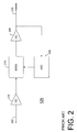
- FIG. 2 is an electrical block diagram of a conventional amplifier 125 that includes an AGC circuit.
- the amplifier 125 receives a forward signal from the upstream path at an input port 205.
- the forward signals being transmitted have been predominately analog channels.
- the forward signal is transmitted through one or more gain stages 210 for amplifying the forward signal.
- the amplified signal is then transmitted through a Bode circuit 215 that varies the signal level by attenuation.
- a final output gain stage 220 subsequently processes the forward signal, which is then transmitted to an output port 225.
- the output of the final gain stage 220 is also coupled to an AGC circuit 230 that is used to further control the attenuation of the Bode circuit 215 in response to the signal level of the amplified forward signal.
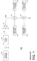
- FIG. 3 is an electrical block diagram of the conventional AGC circuit 230 of FIG. 2 .
- the AGC circuit 230 includes an input port for receiving the forward signal, which is also coupled to the amplifier output 225 of the final gain stage 220.
- the AGC circuit 230 includes a band pass filter 305 and a gain stage 310 for filtering and amplifying, respectively, the pilot signal.
- the filtered signal is then transmitted to an AM detector 315 that demodulates the signal to recover an analog video signal.
- the demodulated analog video signal is amplified through a video amplifier 320.
- a video peak detector 325 then samples the horizontal synchronization pulses of the demodulated video signal in order to establish a DC voltage that represents the peak carrier level.
- the peak detector 325 monitors the DC voltage of the horizontal synchronization pulses of the demodulated video signal to set and hold peak voltage values and to generate a peak voltage signal representative of the peak voltage values. This is generally done by storing the DC voltage values in a capacitor-resistor network between synchronization pulses.
- the DC voltage signal provided by the peak detector 325 is compared with a thermal reference level by the integrator 330 to verify that the gain of the amplifier gain stages has remained constant. If the compared peak voltage signal has dropped below or risen above the predetermined thermal reference level, a thermal reference voltage signal from the reference voltage circuit 335 will be provided at the output of the AGC circuit 230 until such time as the voltage level of the pilot carrier signal level again equals the reference voltage level.
- the input signal is filtered through the band pass filter 305 to allow a predetermined pilot carrier signal to pass.
- the pilot carrier signal is then demodulated and used, through comparison with the reference voltage level, to control the Bode circuit 215 ( FIG. 2 ).
- the frequency of the pilot carrier signal is generally determined by selecting a median point between the lowest channel and the highest channel in the forward frequency spectrum, although the frequency of the pilot carrier may vary as long as the band pass filter 305 and other device components are configured to process a carrier signal of the desired frequency.
- an AGC circuit that can process a pilot carrier signal in the digital frequency spectrum to accurately generate a signal level control.
- communication systems often include amplifiers for boosting signal levels as signals are transmitted to remote subscribers.
- These amplifiers typically include automatic gain control (AGC) circuits for controlling signal levels, but conventional AGC circuits are not suitable for use with both analog and digital pilot signals. Instead, conventional AGC circuits are limited to processing analog input signals.
- AGC automatic gain control
- the amplifiers require an alternative AGC circuit to monitor and control amplifier gain using a digital input signal in addition to conventional analog input signals.
- An advantage of the present invention is that an AGC circuit, which is depicted in FIG. 4 , can be provided to discriminate between an analog forward signal and a digital forward signal and to use either for controlling gain levels within an amplifier.
- One of the functions of an AGC circuit is to capture a representative voltage of the input signal and compare that voltage with a reference signal.
- the AGC circuit of the present invention performs this function whether the input signal is analog or digital.
- the AGC circuit 400 in accordance with the present invention includes an input port that receives a forward input signal and that is coupled to the output of the gain stage of an amplifier.
- the forward input signal is transmitted through a band pass filter 405, which filters the input signal and allows a predetermined pilot carrier signal to pass through to a gain stage 410.
- the pilot carrier signal is normally AM modulated by an analog video signal which can be recovered using an AM detector 415, which also functions as an averager. Then, the demodulated video signal is amplified by the video amplifier 420.
- a digital/analog discriminator circuit 425 processes the video signal provided at the output of the video amplifier 420.
- an analog video signal is provided to a peak detector 450.
- the peak detector 450 then samples the synchronization pulses of the analog video signal in order to establish a DC voltage, which is then compared with a thermal reference level, as will be described in greater detail below.
- the carrier signal will be digitally modulated, e.g., QAM modulated; therefore, the AM detector 415 and the video amplifier 420 have little effect, other than averaging the digital input signal, in representing a peak voltage for the peak detector 450 to capture for comparison.
- the AGC circuit 400 solves this problem by using the digital/analog discriminator circuit 425 to bypass the peak detector 450 when the pilot carrier signal is determined to be a digital signal.
- the digital/analog discriminator circuit 425 includes a band pass filter 430 centered at the horizontal synchronization frequency of the input analog video signal. This frequency is 15.75 KHz for NTSC systems.
- the band pass filter 430 can be retuned to accommodate varying formats, e.g., PAL or SECAM, and various frequencies.
- a delay circuit 432 is coupled at the input of the band pass filter 430 to delay the video signal by a predetermined time to allow the digital/analog discriminator circuit 425 to process the received signal.
- an averaging circuit 435 Following the band pass filter 430 is an averaging circuit 435. The output of the averaging circuit 435 is delivered to a comparator 440.
- the comparator 440 compares the received amplitude of the analog horizontal synchronization pulses from the averaging circuit 435 with a reference voltage.
- This reference voltage is generally proportional to a value between the average value of the digital pilot signal and the average value of the horizontal synchronization pulses. Relative to the reference voltage, the presence of a strong horizontal synchronization pulse from the averaging circuit 435 signifies an analog modulated carrier signal; the presence of a weaker horizontal synchronization pulse from the averaging circuit 435 signifies a digitally modulated carrier signal.
- a separate averaging device should be included in the signal path of the AGC circuit 400.
- This separate averaging device can, for instance, be implemented through use of the integrator 445 and/or a conventional filter that may follow the integrator. Other conventional averaging devices could alternatively be used.
- the output of the comparator 440 controls a switch 51.
- the comparator 440 detects a strong signal from the averager 435, the output of the comparator 440 triggers the switch 51 to its second state and thereby routes the analog video signal from the delay circuit to the input of the peak detector 450.
- the peak detector 450 monitors the DC voltage of the demodulated video signal to set and hold peak voltage values and to generate a peak voltage signal representative of the peak voltage values. This is generally done by storing the DC voltage values in a capacitor-resistor network between synchronization pusles.
- the DC voltage signal provided by the peak detector 450 is compared with a thermal reference level by the integrator 445 to verify that the gain of the amplifier gain stages has remained constant. If the compared peak voltage signal has dropped below or risen above the predetermined thermal reference level, a thermal reference voltage signal provided by a reference voltage circuit 456 is provided at the output of the AGC circuit 400 until such time as the voltage level of the pilot signal again equals the reference voltage level.
- the output of the comparator 440 triggers the switch 51 to its first state that then routes the digital video signal, bypassing the peak detector 450, to the input of the integrator 445.
- the averaged digital video signal is then compared to a thermal reference voltage signal at the integrator 445. If the compared averaged digital signal has dropped below or risen above the predetermined thermal reference level, a thermal digital reference voltage signal provided by a digital reference voltage circuit 455, will be provided at the output of the AGC circuit 400 until such time as the voltage level of the pilot signal again equals the reference voltage level.
- a switch 460 has a first state that represents a digital reference voltage level and a second state that represents an analog voltage reference level.
- This switch 460 can be operated in several methods, e.g., manually decided upon at the time of installation, or operated by an electronic switching circuit under control of the comparator 440 in the digital/analog discriminator circuit 425. It can also be appreciated that there may not be the need for two separate thermally compensated reference voltage circuits. Instead, the AGC circuit can include a single thermally compensated reference voltage circuit with a reference voltage that will satisfy both the digital and the analog signal constraints.
- a communication system such as a cable television system
- a communication system is able to use a single AGC circuit to monitor and control the gain of the amplifiers regardless of whether the forward signal is digital or analog.
- a system operator can install one AGC circuit at the time of amplifier deployment in order to increase flexibility in implementing digital communication systems. Consequently, installing an AGC circuit once, as opposed to visiting each amplifier and installing a new AGC circuit when an analog system begins to transmit digital signals, can save time and labor. Additionally, selection between processing of a digital pilot signal and processing of an analog pilot signal is automatic, and manual selection is not necessary.
- the AGC circuit described above discriminates between an analog signal and a digital signal. It is therefore able to detect an analog modulated peak voltage, or alternatively, utilize an averager to average the digital signal which is a representation of the peak carrier level for the respective forward signals and, compare that voltage to a reference voltage. The AGC circuit then further controls the amplitude of the signal provided to the gain stages of the amplifier.
- analog and digital signal level control circuits can conveniently operate within the same amplifier to detect and process analog and digital signals automatically, permitting a greater degree of flexibility than is currently the case for prior art signal level control circuits.
Landscapes
- Engineering & Computer Science (AREA)
- Multimedia (AREA)
- Signal Processing (AREA)
- Control Of Amplification And Gain Control (AREA)
- Circuits Of Receivers In General (AREA)
Description
- This invention relates generally to amplifiers, and more specifically to automatic gain control (AGC) circuits.
- A
communication system 100, such as a two-way cable television system, is depicted inFIG. 1 . Thecommunication system 100 includesheadend equipment 105 for generating forward signals that are transmitted in the downstream direction along a communication medium, such as a fiberoptic cable 110, to anoptical node 115 that converts optical signals to radio frequency (RF) signals. The RF signals are further transmitted along another communication medium, such ascoaxial cable 120, and are amplified, as necessary, by one ormore distribution amplifiers 125 positioned along the communication medium.Taps 130 included in the cable television system split off portions of the forward signals for provision tosubscriber equipment 135, such as set top terminals, computers, and televisions. In a two-way system, thesubscriber equipment 135 can also generate reverse signals that are transmitted upstream, amplified by anydistribution amplifiers 125, converted to optical signals, and provided to theheadend equipment 105. - Communication systems, as depicted in
FIG. 1 , often include amplifiers to boost signal levels, and automatic gain control (AGC) circuits within the amplifier are typically used to monitor and control the gain of such amplifiers, see for example patentUS 5,408,698 . -
FIG. 2 is an electrical block diagram of aconventional amplifier 125 that includes an AGC circuit. In operation, theamplifier 125 receives a forward signal from the upstream path at aninput port 205. In conventional cable television systems, the forward signals being transmitted have been predominately analog channels. The forward signal is transmitted through one ormore gain stages 210 for amplifying the forward signal. The amplified signal is then transmitted through aBode circuit 215 that varies the signal level by attenuation. A finaloutput gain stage 220 subsequently processes the forward signal, which is then transmitted to anoutput port 225. The output of thefinal gain stage 220 is also coupled to anAGC circuit 230 that is used to further control the attenuation of theBode circuit 215 in response to the signal level of the amplified forward signal. -
FIG. 3 is an electrical block diagram of theconventional AGC circuit 230 ofFIG. 2 . TheAGC circuit 230 includes an input port for receiving the forward signal, which is also coupled to theamplifier output 225 of thefinal gain stage 220. TheAGC circuit 230 includes aband pass filter 305 and again stage 310 for filtering and amplifying, respectively, the pilot signal. The filtered signal is then transmitted to anAM detector 315 that demodulates the signal to recover an analog video signal. Next, the demodulated analog video signal is amplified through avideo amplifier 320. - A
video peak detector 325 then samples the horizontal synchronization pulses of the demodulated video signal in order to establish a DC voltage that represents the peak carrier level. Thepeak detector 325 monitors the DC voltage of the horizontal synchronization pulses of the demodulated video signal to set and hold peak voltage values and to generate a peak voltage signal representative of the peak voltage values. This is generally done by storing the DC voltage values in a capacitor-resistor network between synchronization pulses. - The DC voltage signal provided by the
peak detector 325 is compared with a thermal reference level by theintegrator 330 to verify that the gain of the amplifier gain stages has remained constant. If the compared peak voltage signal has dropped below or risen above the predetermined thermal reference level, a thermal reference voltage signal from thereference voltage circuit 335 will be provided at the output of theAGC circuit 230 until such time as the voltage level of the pilot carrier signal level again equals the reference voltage level. - Again referring to the forward input signal to the
AGC circuit 230, the input signal is filtered through theband pass filter 305 to allow a predetermined pilot carrier signal to pass. The pilot carrier signal is then demodulated and used, through comparison with the reference voltage level, to control the Bode circuit 215 (FIG. 2 ). The frequency of the pilot carrier signal is generally determined by selecting a median point between the lowest channel and the highest channel in the forward frequency spectrum, although the frequency of the pilot carrier may vary as long as theband pass filter 305 and other device components are configured to process a carrier signal of the desired frequency. - Historically, cable television systems have transmitted only analog signals, so transmission and processing of an analog pilot carrier signal by conventional analog AGC circuits has worked well. The cable television industry, however, is migrating to transmission of digital signals, so a pilot carrier signal in the digital frequency spectrum may, in the future, be chosen for processing through the AGC circuit. These digital signals are generally QAM modulated, and QAM modulated digital signals cannot be accurately processed by prior art AGC circuits, such as the
AGC circuit 230 shown inFIG. 3 . More specifically, the DC voltage values of the QAM modulated signals include complex, multilevel data having peak values at varying times and different rates, so peak detection in an AGC circuit does not provide useful or accurate information. - Thus, what is needed is an AGC circuit that can process a pilot carrier signal in the digital frequency spectrum to accurately generate a signal level control.
-
-
FIG. 1 is a block diagram of a conventional communication system, such as a cable television system. -
FIG. 2 is a block diagram of a conventional amplifier included in the communication system ofFIG. 1 . -
FIG. 3 is a block diagram of the conventional AGC circuit included in the amplifier ofFIG. 2 . -
FIG. 4 is a block diagram of an AGC circuit for processing analog and digital signals in accordance with the present invention. - As briefly mentioned in the Background of the Invention, communication systems often include amplifiers for boosting signal levels as signals are transmitted to remote subscribers. These amplifiers typically include automatic gain control (AGC) circuits for controlling signal levels, but conventional AGC circuits are not suitable for use with both analog and digital pilot signals. Instead, conventional AGC circuits are limited to processing analog input signals. With cable television systems migrating to a digital format, the amplifiers require an alternative AGC circuit to monitor and control amplifier gain using a digital input signal in addition to conventional analog input signals.
- An advantage of the present invention is that an AGC circuit, which is depicted in
FIG. 4 , can be provided to discriminate between an analog forward signal and a digital forward signal and to use either for controlling gain levels within an amplifier. One of the functions of an AGC circuit is to capture a representative voltage of the input signal and compare that voltage with a reference signal. The AGC circuit of the present invention performs this function whether the input signal is analog or digital. - Referring to
FIG. 4 , theAGC circuit 400 in accordance with the present invention includes an input port that receives a forward input signal and that is coupled to the output of the gain stage of an amplifier. The forward input signal is transmitted through aband pass filter 405, which filters the input signal and allows a predetermined pilot carrier signal to pass through to again stage 410. The pilot carrier signal is normally AM modulated by an analog video signal which can be recovered using anAM detector 415, which also functions as an averager. Then, the demodulated video signal is amplified by thevideo amplifier 420. - Next, a digital/analog discriminator circuit 425 processes the video signal provided at the output of the
video amplifier 420. As a result of processing by the discriminator circuit 425, an analog video signal is provided to apeak detector 450. Thepeak detector 450 then samples the synchronization pulses of the analog video signal in order to establish a DC voltage, which is then compared with a thermal reference level, as will be described in greater detail below. - However, if the input signal is digital, rather than being analog, the carrier signal will be digitally modulated, e.g., QAM modulated; therefore, the
AM detector 415 and thevideo amplifier 420 have little effect, other than averaging the digital input signal, in representing a peak voltage for thepeak detector 450 to capture for comparison. TheAGC circuit 400 solves this problem by using the digital/analog discriminator circuit 425 to bypass thepeak detector 450 when the pilot carrier signal is determined to be a digital signal. - The digital/analog discriminator circuit 425 includes a
band pass filter 430 centered at the horizontal synchronization frequency of the input analog video signal. This frequency is 15.75 KHz for NTSC systems. Theband pass filter 430 can be retuned to accommodate varying formats, e.g., PAL or SECAM, and various frequencies. In addition, adelay circuit 432 is coupled at the input of theband pass filter 430 to delay the video signal by a predetermined time to allow the digital/analog discriminator circuit 425 to process the received signal. Following theband pass filter 430 is anaveraging circuit 435. The output of theaveraging circuit 435 is delivered to acomparator 440. Thecomparator 440 compares the received amplitude of the analog horizontal synchronization pulses from theaveraging circuit 435 with a reference voltage. This reference voltage is generally proportional to a value between the average value of the digital pilot signal and the average value of the horizontal synchronization pulses. Relative to the reference voltage, the presence of a strong horizontal synchronization pulse from theaveraging circuit 435 signifies an analog modulated carrier signal; the presence of a weaker horizontal synchronization pulse from theaveraging circuit 435 signifies a digitally modulated carrier signal. - One of ordinary skill in the art will appreciate that, when the
AM detector 415 does not function as an averager, a separate averaging device should be included in the signal path of theAGC circuit 400. This separate averaging device can, for instance, be implemented through use of theintegrator 445 and/or a conventional filter that may follow the integrator. Other conventional averaging devices could alternatively be used. - The output of the
comparator 440 controls a switch 51. When thecomparator 440 detects a strong signal from theaverager 435, the output of thecomparator 440 triggers the switch 51 to its second state and thereby routes the analog video signal from the delay circuit to the input of thepeak detector 450. Thepeak detector 450 monitors the DC voltage of the demodulated video signal to set and hold peak voltage values and to generate a peak voltage signal representative of the peak voltage values. This is generally done by storing the DC voltage values in a capacitor-resistor network between synchronization pusles. - The DC voltage signal provided by the
peak detector 450 is compared with a thermal reference level by theintegrator 445 to verify that the gain of the amplifier gain stages has remained constant. If the compared peak voltage signal has dropped below or risen above the predetermined thermal reference level, a thermal reference voltage signal provided by areference voltage circuit 456 is provided at the output of theAGC circuit 400 until such time as the voltage level of the pilot signal again equals the reference voltage level. - When the
comparator 440 detects a weak signal, which is indicative of a digital input signal, the output of thecomparator 440 triggers the switch 51 to its first state that then routes the digital video signal, bypassing thepeak detector 450, to the input of theintegrator 445. The averaged digital video signal is then compared to a thermal reference voltage signal at theintegrator 445. If the compared averaged digital signal has dropped below or risen above the predetermined thermal reference level, a thermal digital reference voltage signal provided by a digitalreference voltage circuit 455, will be provided at the output of theAGC circuit 400 until such time as the voltage level of the pilot signal again equals the reference voltage level. - Referring to the thermally compensated reference voltages in
FIG. 4 , aswitch 460 has a first state that represents a digital reference voltage level and a second state that represents an analog voltage reference level. Thisswitch 460 can be operated in several methods, e.g., manually decided upon at the time of installation, or operated by an electronic switching circuit under control of thecomparator 440 in the digital/analog discriminator circuit 425. It can also be appreciated that there may not be the need for two separate thermally compensated reference voltage circuits. Instead, the AGC circuit can include a single thermally compensated reference voltage circuit with a reference voltage that will satisfy both the digital and the analog signal constraints. - According to the present invention, a communication system, such as a cable television system, is able to use a single AGC circuit to monitor and control the gain of the amplifiers regardless of whether the forward signal is digital or analog. As a result, a system operator can install one AGC circuit at the time of amplifier deployment in order to increase flexibility in implementing digital communication systems. Consequently, installing an AGC circuit once, as opposed to visiting each amplifier and installing a new AGC circuit when an analog system begins to transmit digital signals, can save time and labor. Additionally, selection between processing of a digital pilot signal and processing of an analog pilot signal is automatic, and manual selection is not necessary.
- In summary, the AGC circuit described above discriminates between an analog signal and a digital signal. It is therefore able to detect an analog modulated peak voltage, or alternatively, utilize an averager to average the digital signal which is a representation of the peak carrier level for the respective forward signals and, compare that voltage to a reference voltage. The AGC circuit then further controls the amplitude of the signal provided to the gain stages of the amplifier. As a result, alternative analog and digital signal level control circuits can conveniently operate within the same amplifier to detect and process analog and digital signals automatically, permitting a greater degree of flexibility than is currently the case for prior art signal level control circuits.
Claims (17)
- An automatic gain control (AGC) circuit (400), comprising:an input port for receiving an input signal that is one of a digital input signal and an analog input signal;a comparator (440) coupled to the input port for determining which of the digital input signal and the analog input signal has been received;an averager (415) for averaging the digital input signal to generate an average voltage signal when the input signal is determined to be digital;a peak detector (450) for generating a peak voltage signal from the analog input signal when the input signal is determined to be analog; andan output port for providing the average voltage signal when the input signal is determined to be digital and for providing the peak voltage signal when the input signal is determined to be analog.
- The AGC circuit (400) of claim 1, wherein the comparator (440) comprises:a first input for receiving the input signal;a second input for receiving a reference voltage; andan output for providing a control signal indicating which of the digital input signal and the analog input signal has been received.
- The AGC circuit (400) of claim 2, further comprising:a thermally compensated reference voltage circuit (455,456) for generating reference voltage levels under control of the comparator (440).
- The AGC circuit (400) of claim 3, wherein the thermally compensated reference voltage circuit (455) generates a digital reference voltage level when the input signal is determined to be digital, and wherein the thermally compensated reference voltage circuit (456) generates an analog reference voltage level when the input signal is determined to be analog.
- The AGC circuit (400) in claim 1, further comprising:an integrator (445) coupled to the thermally compensated reference voltage circuit for comparing the average voltage signal with the digital reference voltage level when the input signal is determined to be digital and for comparing the peak voltage signal with the analog reference voltage level when the input signal is determined to be analog.
- The AGC circuit of claim 1, further comprising:a switch (S1) having first and second switch settings, wherein the switch is controlled by the comparator, wherein the first switch setting of the switch is activated when the input signal is determined to be digital and provides the average voltage signal to the integrator (445), and wherein the second switch setting of the switch is activated when the input signal is determined to be analog and provides the analog input signal to the peak detector (450).
- An amplifier having automatic gain control (AGC) circuit, the amplifier comprising:at least one gain stage for amplifying a signal received by the amplifier, the gain stage comprising an input terminal and an output terminal; andan AGC circuit according to claim 1 for controlling attenuation of the signal in the gain stage,wherein an input of the AGC circuit is coupled to the output terminal of the gain stage for receiving a pilot signal with a video signal component and an output of the AGC circuit is coupled to the input terminal of the gain stage for providing a level control signal thereto.
- The amplifier of claim 7, further comprising:a thermally compensated reference voltage circuit for generating reference voltage levels under control of the comparator.
- The amplifier of claim 7, further comprising:a switch having first and second switch settings,wherein the switch is controlled by the comparator,
wherein the first switch setting of the switch generates a digital reference voltage level from the thermally compensated reference voltage circuit when the pilot signal is determined to be digital, and wherein the second switch setting of the switch generates an analog reference voltage level from the thermally compensated reference voltage circuit when the pilot signal is determined to be analog. - The amplifier of claim 7, further comprising:an integrator coupled to the switch for comparing the average voltage signal with the first switch setting when the pilot signal is determined to be digital and comparing the peak voltage signal with the second switch setting when the pilot signal is determined to be analog.
- The amplifier of claim 10, wherein the integrator has an output to provide the level control signal.
- A communication system for providing information, the communication system comprising:a transmitter for transmitting a signal including the information;a receiver for receiving the signal; andan amplifier coupled between the transmitter and the receiver for amplifying the signal, the amplifier comprising:wherein the AGC circuit automatically controls the attenuation of the signal in the gain stage when the input signal is digital and when the input signal is analog.a gain stage for amplifying the signal received by the amplifier; and an automatic gain control (AGC) circuit according to claim 1 for controlling the attenuation of the signal in the gain stage,
- The communication system of claim 12, wherein the AGC circuit further comprises:an averager for averaging the digital input signal to generate an average voltage signal; anda peak detector for generating a peak voltage signal from the analog input signal.
- The communication system of claim 12, wherein the AGC circuit further includes a thermally compensated reference voltage circuit for generating reference voltage levels under control of the comparator.
- The communication system of claim 14, wherein the thermally compensated reference voltage circuit generates a digital reference voltage level when the input signal is determined to be digital and an analog reference voltage level when the input signal is determined to be analog.
- The communication system of claim 12, wherein the AGC circuit further comprises an integrator coupled to the thermally compensated reference voltage circuit comparing the average voltage signal and the digital reference voltage level when the input signal is determined to be digital and comparing the peak voltage signal and the analog reference voltage level when the input signal is determined to be analog.
- The communication system of claim 16, wherein the integrator has an output to provide the output signal that controls the signal level.
Applications Claiming Priority (3)
| Application Number | Priority Date | Filing Date | Title |
|---|---|---|---|
| US09/632,526 US6995806B1 (en) | 2000-08-04 | 2000-08-04 | Amplifier with a universal automatic gain control circuit |
| US632526 | 2000-08-04 | ||
| PCT/US2001/024307 WO2002013379A2 (en) | 2000-08-04 | 2001-08-03 | Amplifier with a universal automatic gain control circuit |
Publications (2)
| Publication Number | Publication Date |
|---|---|
| EP1314245A2 EP1314245A2 (en) | 2003-05-28 |
| EP1314245B1 true EP1314245B1 (en) | 2010-03-03 |
Family
ID=24535855
Family Applications (1)
| Application Number | Title | Priority Date | Filing Date |
|---|---|---|---|
| EP01959453A Expired - Lifetime EP1314245B1 (en) | 2000-08-04 | 2001-08-03 | Amplifier with a universal automatic gain control circuit |
Country Status (5)
| Country | Link |
|---|---|
| US (1) | US6995806B1 (en) |
| EP (1) | EP1314245B1 (en) |
| DE (2) | DE1314245T1 (en) |
| ES (1) | ES2195800T1 (en) |
| WO (1) | WO2002013379A2 (en) |
Families Citing this family (4)
| Publication number | Priority date | Publication date | Assignee | Title |
|---|---|---|---|---|
| JP3773873B2 (en) * | 2002-05-24 | 2006-05-10 | 三洋電機株式会社 | Broadcast receiver |
| US7787850B2 (en) * | 2007-09-05 | 2010-08-31 | Broadcom Corporation | Multi-input multi-output transceiver with power consumption management based on receiver parameter and method for use therewith |
| JP5596860B2 (en) * | 2011-06-30 | 2014-09-24 | 日本電信電話株式会社 | Automatic gain adjustment circuit |
| US9166546B2 (en) | 2011-10-24 | 2015-10-20 | Cochlear Limited | Post-filter common-gain determination |
Family Cites Families (10)
| Publication number | Priority date | Publication date | Assignee | Title |
|---|---|---|---|---|
| US4371842A (en) * | 1980-10-24 | 1983-02-01 | Sperry Corporation | Self-adjusting dual mode automatic gain control circuit |
| JPS57143950A (en) | 1981-03-03 | 1982-09-06 | Nec Corp | Monitoring circuit for auxiliary circuit |
| US4434439A (en) | 1982-02-22 | 1984-02-28 | Rca Corporation | Digital television AGC arrangement |
| US4797735A (en) | 1985-07-04 | 1989-01-10 | Matsushita Electric Industrial Co., Ltd. | Distortion surveillance apparatus for television signal transmission system |
| US5187809A (en) * | 1990-08-24 | 1993-02-16 | Motorola, Inc. | Dual mode automatic gain control |
| JPH04297115A (en) | 1991-03-26 | 1992-10-21 | Toshiba Corp | Variable gain control circuit |
| US5293405A (en) | 1991-10-31 | 1994-03-08 | International Business Machines Corp. | Adaptive equalization and regeneration system |
| US5565932A (en) | 1994-11-08 | 1996-10-15 | Zenith Electronics Corp. | AGC system with pilot using digital data reference |
| US5841814A (en) | 1995-10-17 | 1998-11-24 | Paradyne Corporation | Sampling system for radio frequency receiver |
| US6725463B1 (en) * | 1997-08-01 | 2004-04-20 | Microtune (Texas), L.P. | Dual mode tuner for co-existing digital and analog television signals |
-
2000
- 2000-08-04 US US09/632,526 patent/US6995806B1/en not_active Expired - Lifetime
-
2001
- 2001-08-03 DE DE1314245T patent/DE1314245T1/en active Pending
- 2001-08-03 ES ES01959453T patent/ES2195800T1/en active Pending
- 2001-08-03 WO PCT/US2001/024307 patent/WO2002013379A2/en not_active Ceased
- 2001-08-03 EP EP01959453A patent/EP1314245B1/en not_active Expired - Lifetime
- 2001-08-03 DE DE60141469T patent/DE60141469D1/en not_active Expired - Lifetime
Also Published As
| Publication number | Publication date |
|---|---|
| DE60141469D1 (en) | 2010-04-15 |
| DE1314245T1 (en) | 2003-11-27 |
| ES2195800T1 (en) | 2003-12-16 |
| EP1314245A2 (en) | 2003-05-28 |
| WO2002013379A2 (en) | 2002-02-14 |
| WO2002013379A3 (en) | 2003-03-06 |
| US6995806B1 (en) | 2006-02-07 |
Similar Documents
| Publication | Publication Date | Title |
|---|---|---|
| EP0064819B1 (en) | An fm signal demodulation system | |
| US5892396A (en) | Method and apparatus for controlling gain of a power amplifier | |
| EP0750405B1 (en) | Cable loss equalization system used in wireless communication equipment | |
| US6757910B1 (en) | Adaptive filter for reducing ingress noise in CATV return signals | |
| US5095534A (en) | Radio receiver having improved signal-to-noise ratio for receiving voice and data signals | |
| US4148069A (en) | Automatic cable loss compensator for use in a television camera system | |
| US6995806B1 (en) | Amplifier with a universal automatic gain control circuit | |
| US6242982B1 (en) | Amplifier with self setting automatic gain control circuit | |
| US6091441A (en) | Radio frequency detector for cable television distribution systems | |
| EP2171842B1 (en) | Amplifier automatic gain control circuit for QAM modulated and continuous wave signals | |
| US6567118B1 (en) | Frequency agile adaptive automatic gain control circuit | |
| EP0777382A2 (en) | Method and apparatus for selecting a broadcast channel | |
| US6281945B1 (en) | VSB—dependent automatic gain control | |
| EP1615430B1 (en) | Automatic gain control circuit | |
| KR100258626B1 (en) | Cctv system | |
| EP0398351A2 (en) | Apparatus for detecting broadcast FM satellite waves | |
| EP1099302B1 (en) | Signal level control circuit for amplifiers | |
| JP3099287B2 (en) | Transmission status display device of transmission signal processing device | |
| JP3280230B2 (en) | Protector with adjustment function for upstream band signal level | |
| US5262859A (en) | Video signal transmitter/receiver | |
| JPH05252114A (en) | Automatic transmission line switching device | |
| AU677330B2 (en) | AGC for broadband transmitter | |
| JP2737493B2 (en) | Diversity receiver | |
| JPH01220949A (en) | Detecting circuit for out-band signaling signal | |
| JPH06189313A (en) | Satellite broadcasting receiver |
Legal Events
| Date | Code | Title | Description |
|---|---|---|---|
| PUAI | Public reference made under article 153(3) epc to a published international application that has entered the european phase |
Free format text: ORIGINAL CODE: 0009012 |
|
| 17P | Request for examination filed |
Effective date: 20030218 |
|
| AK | Designated contracting states |
Designated state(s): AT BE CH CY DE DK ES FI FR GB GR IE IT LI LU MC NL PT SE TR |
|
| AX | Request for extension of the european patent |
Extension state: AL LT LV MK RO SI |
|
| DET | De: translation of patent claims | ||
| RBV | Designated contracting states (corrected) |
Designated state(s): DE ES GB |
|
| 17Q | First examination report despatched |
Effective date: 20060828 |
|
| GRAP | Despatch of communication of intention to grant a patent |
Free format text: ORIGINAL CODE: EPIDOSNIGR1 |
|
| GRAS | Grant fee paid |
Free format text: ORIGINAL CODE: EPIDOSNIGR3 |
|
| GRAA | (expected) grant |
Free format text: ORIGINAL CODE: 0009210 |
|
| AK | Designated contracting states |
Kind code of ref document: B1 Designated state(s): DE ES GB |
|
| REG | Reference to a national code |
Ref country code: GB Ref legal event code: FG4D |
|
| REF | Corresponds to: |
Ref document number: 60141469 Country of ref document: DE Date of ref document: 20100415 Kind code of ref document: P |
|
| PG25 | Lapsed in a contracting state [announced via postgrant information from national office to epo] |
Ref country code: ES Free format text: LAPSE BECAUSE OF FAILURE TO SUBMIT A TRANSLATION OF THE DESCRIPTION OR TO PAY THE FEE WITHIN THE PRESCRIBED TIME-LIMIT Effective date: 20100614 |
|
| PLBE | No opposition filed within time limit |
Free format text: ORIGINAL CODE: 0009261 |
|
| STAA | Information on the status of an ep patent application or granted ep patent |
Free format text: STATUS: NO OPPOSITION FILED WITHIN TIME LIMIT |
|
| 26N | No opposition filed |
Effective date: 20101206 |
|
| GBPC | Gb: european patent ceased through non-payment of renewal fee |
Effective date: 20100803 |
|
| PG25 | Lapsed in a contracting state [announced via postgrant information from national office to epo] |
Ref country code: GB Free format text: LAPSE BECAUSE OF NON-PAYMENT OF DUE FEES Effective date: 20100803 |
|
| REG | Reference to a national code |
Ref country code: DE Ref legal event code: R082 Ref document number: 60141469 Country of ref document: DE Representative=s name: TBK, DE Ref country code: DE Ref legal event code: R081 Ref document number: 60141469 Country of ref document: DE Owner name: CISCO TECHNOLOGY, INC., SAN JOSE, US Free format text: FORMER OWNER: SCIENTIFIC-ATLANTA, INC., LAWRENCEVILLE, GA., US |
|
| PGFP | Annual fee paid to national office [announced via postgrant information from national office to epo] |
Ref country code: DE Payment date: 20190828 Year of fee payment: 19 |
|
| REG | Reference to a national code |
Ref country code: DE Ref legal event code: R119 Ref document number: 60141469 Country of ref document: DE |
|
| PG25 | Lapsed in a contracting state [announced via postgrant information from national office to epo] |
Ref country code: DE Free format text: LAPSE BECAUSE OF NON-PAYMENT OF DUE FEES Effective date: 20210302 |