EP1313328A2 - Stereoscopic camera with luminance difference adjustement - Google Patents
Stereoscopic camera with luminance difference adjustement Download PDFInfo
- Publication number
- EP1313328A2 EP1313328A2 EP02025640A EP02025640A EP1313328A2 EP 1313328 A2 EP1313328 A2 EP 1313328A2 EP 02025640 A EP02025640 A EP 02025640A EP 02025640 A EP02025640 A EP 02025640A EP 1313328 A2 EP1313328 A2 EP 1313328A2
- Authority
- EP
- European Patent Office
- Prior art keywords
- brightness
- adjusting
- images
- offset
- pair
- Prior art date
- Legal status (The legal status is an assumption and is not a legal conclusion. Google has not performed a legal analysis and makes no representation as to the accuracy of the status listed.)
- Withdrawn
Links
Images



Classifications
-
- H—ELECTRICITY
- H04—ELECTRIC COMMUNICATION TECHNIQUE
- H04N—PICTORIAL COMMUNICATION, e.g. TELEVISION
- H04N13/00—Stereoscopic video systems; Multi-view video systems; Details thereof
- H04N13/10—Processing, recording or transmission of stereoscopic or multi-view image signals
- H04N13/106—Processing image signals
- H04N13/133—Equalising the characteristics of different image components, e.g. their average brightness or colour balance
-
- H—ELECTRICITY
- H04—ELECTRIC COMMUNICATION TECHNIQUE
- H04N—PICTORIAL COMMUNICATION, e.g. TELEVISION
- H04N13/00—Stereoscopic video systems; Multi-view video systems; Details thereof
- H04N13/20—Image signal generators
- H04N13/204—Image signal generators using stereoscopic image cameras
- H04N13/239—Image signal generators using stereoscopic image cameras using two two-dimensional [2D] image sensors having a relative position equal to or related to the interocular distance
-
- H—ELECTRICITY
- H04—ELECTRIC COMMUNICATION TECHNIQUE
- H04N—PICTORIAL COMMUNICATION, e.g. TELEVISION
- H04N13/00—Stereoscopic video systems; Multi-view video systems; Details thereof
- H04N13/20—Image signal generators
- H04N13/296—Synchronisation thereof; Control thereof
-
- H—ELECTRICITY
- H04—ELECTRIC COMMUNICATION TECHNIQUE
- H04N—PICTORIAL COMMUNICATION, e.g. TELEVISION
- H04N13/00—Stereoscopic video systems; Multi-view video systems; Details thereof
- H04N13/10—Processing, recording or transmission of stereoscopic or multi-view image signals
- H04N13/106—Processing image signals
- H04N13/111—Transformation of image signals corresponding to virtual viewpoints, e.g. spatial image interpolation
-
- H—ELECTRICITY
- H04—ELECTRIC COMMUNICATION TECHNIQUE
- H04N—PICTORIAL COMMUNICATION, e.g. TELEVISION
- H04N13/00—Stereoscopic video systems; Multi-view video systems; Details thereof
- H04N13/10—Processing, recording or transmission of stereoscopic or multi-view image signals
- H04N13/189—Recording image signals; Reproducing recorded image signals
-
- H—ELECTRICITY
- H04—ELECTRIC COMMUNICATION TECHNIQUE
- H04N—PICTORIAL COMMUNICATION, e.g. TELEVISION
- H04N13/00—Stereoscopic video systems; Multi-view video systems; Details thereof
- H04N13/20—Image signal generators
- H04N13/204—Image signal generators using stereoscopic image cameras
- H04N13/246—Calibration of cameras
-
- H—ELECTRICITY
- H04—ELECTRIC COMMUNICATION TECHNIQUE
- H04N—PICTORIAL COMMUNICATION, e.g. TELEVISION
- H04N13/00—Stereoscopic video systems; Multi-view video systems; Details thereof
- H04N2013/0074—Stereoscopic image analysis
- H04N2013/0081—Depth or disparity estimation from stereoscopic image signals
Definitions
- the present invention relates to an adjusting apparatus of a stereoscopic camera and more particularly to an adjusting apparatus for adjusting a brightness difference between a pair of stereoscopic images.
- a stereoscopic image processing in which a pair of cameras take a picture image of an object from different positions, respectively and a distance to the object is obtained from a parallax between two cameras on the paired picture images based on a position where the cameras are installed and parameters such as a focal distance of the camera according to the principle of a triangulation, is known.
- the parallax between two cameras with respect to the object is obtained when two image signals are overlapped and coincide with each other, while two image signals are shifted one by one. It is preferable that there is no deviation except for the parallax between two images and it is required that the balance of optical characteristics and the balance of signal characteristics are secured between those two cameras.
- the applicant of the present invention proposes a technique in which the brightness balance between respective images of the stereoscopic camera is adjusted by correcting a gain of an amplifier so as to minimize the difference between a first evaluation value representing a magnitude of overall brightness of a first window provided in one image of the stereoscopic camera and a second evaluation value representing a magnitude of overall brightness of a second window provided in the other image of the stereoscopic camera.
- the two cameras constituting the stereoscopic camera have dispersions in their characteristics respectively and have a different direct current component in output signals of the respective cameras.
- a black level which is a reference value in processing images disagrees between the paired image signals.
- the disagreement of the black level means that the respective images after A/D conversion have a different brightness level and there is a brightness offset deviation between images.
- the brightness offset deviation can not be deleted by simply adjusting gains of an amplifier as the prior art does and this has been an obstacle in enhancing the accuracy of stereoscopic image processing.
- An adjusting apparatus for adjusting a brightness balance between a pair of images taken by a stereoscopic camera comprises an offset amount adjusting means for adjusting a brightness offset of the images and an offset deviation adjusting means for adjusting a deviation of the brightness offset between the pair of images by correcting the brightness offset based on a difference of brightness distribution between the pair of images.
- the difference of brightness distribution is represented by a deviation of brightness in a lateral direction of histograms of the paired images with respect to brightness.
- the deviation is converted into a correction amount of a clamp value and the correction amount is outputted to a clamp circuit to equalize the brightness balance between images.
- numeral 1 denotes a stereoscopic camera constituted by two cameras 2,3 incorporating image sensors such as a charge coupled device (CCD) and the like and synchronized with each other.
- the cameras 2 and 3 may be designated as a right camera, a left camera respectively.
- the cameras 2, 3 are attached to stays (not shown) extending from a vehicle body with a specified base length.
- An image taken by one camera is referred to as a base image and an image taken by the other camera is referred to as a comparison image.
- the respective cameras 2, 3 are connected with amplifiers 4, 5 for proportionally amplifying image signals from the respective cameras 2, 3. Further, the amplifiers 4, 5 are connected through clamp circuits 6, 7 with A/D converters 8, 9 respectively. Analogue images taken by the respective cameras 2, 3 are converted into digital images having a specified number of gradations (for example, 256 gradations in gray scale).
- the clamp circuits 6, 7 serve as a level adjusting means for fixing (clamping) a black level of respective image signals outputted from the amplifiers 4, 5 to regulate the black level within a voltage range needed for A/D conversions.
- a reference voltage value when an A/D conversion is performed in the A/D converters 8, 9 can be established from outside.
- the reference voltage value is a voltage value of the black level and brightness is regarded as 0 (zero) when the output voltage is lower than the reference voltage value.
- the clamp circuits 6, 7 raise or lower a brightness offset value, namely a clamp value of the black level based on the indication from outside so as to equalize brightness levels of left and right images.
- a deviation between the brightness offset values of the left and right images can be deleted.
- the clamp value given to the clamp circuit 7 on the left image side can be varied so as to equalize the brightness level of the left image with that of the right image.
- the left and right images digitalized in the A/D converters 8,9 are inputted to a correction circuit 10 and are subjected to corrections such as a shading correction, a log correction, a geometrical correction (correction with respect to optical deviations of the cameras 2, 3) and the like.
- the left and right digital image data are stored in an image data memory 11 and at the same time those image data are inputted to a parallax calculating circuit 12 wherein a stereo matching is performed.
- the stereo matching is a process in which an identical object imaged on the left and right images is searched for every specified small region of a picture image to obtain a parallax of the object between the left and right images. Further, the parallax data thus obtained by the stereo matching process are stored in a parallax data memory 13.
- the identical object imaged on the left and right images lies on an epipoler line (a line in parallel with a line connecting both optical centers of the left and right cameras 2, 3) and a deviation amount on the epipoler line between respective positions of the object on the left and right images represents a distance to the object. Therefore, in the parallax calculating circuit 12, a correlation between a small region on the base image and a small region on the comparison image is evaluated while the small region on the comparison image is shifted in a lateral direction pixel by pixel.
- the correlation between the small regions can be evaluated by calculating a city block distance. That is, establishing a coordinate system composed of a lateral axis i and a vertical axis j with an origin of the coordinates placed at the left above corner of the image, and letting a small region be a region of 4 x 4 pixels, the city block distance Z is ( ⁇
- : i, j 0 to 3) where Ai,j is a brightness of a coordinate (i, j) on the base image and Bi, j is a brightness of a corrdinate (i, j) on the comparison image.
- the respective small regions are positions corresponding to an identical object on the same sight line.
- the deviation amount between corresponding small regions is outputted as parallax data representing the distance to the object.
- the construction and operation of the hardware circuit for calculating the city block distance and producing the parallax data are described in detail in Japanese Patent Application Laid-open No.Toku-Kai-Hei 5-114099.
- the pair of original left and right images stored in the image data memory 11 and the parallax data stored in a parallax data memory 13 are inputted to an image processing apparatus 14 and are subjected to miscellaneous image processings therein.
- the image processing apparatus 14 are constituted mainly by a micro computer and other interface circuits, functionally including a recognition section 15 in which the position of an own vehicle and surrounding circumstances are recognized based on the original left and right images of the image data memory 11 and on the parallax data of the parallax data memory 13, and a brightness offset adjusting section 16 in which clamp values with respect to the clamp circuits 6, 7 are calculated based on the original left and right images of the image data memory 11 to adjust the deviation of the brightness offset between the left and right images.
- the adjustment of the deviation of the brightness offset in the brightness offset adjusting section 16 is a software process in which a brightness distribution is obtained for the respective paired images taken by the stereoscopic camera 1 and respective reference voltage values of the clamp circuits 6, 7 are adjusted based on the difference of brightness distribution between the respective images.
- a brightness histogram is prepared for the respective paired images, a deviation of the respective brightness histograms in a direction of a brightness axis is obtained, the deviation is converted into the adjustment value of the reference voltage value and finally the sum of the adjustment value and the present clamp value is outputted as a corrected clamp value.
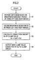
- the brightness offset adjusting section 16 realizes a function as a brightness offset adjusting means and specifically a function of the brightness offset adjusting means is realized by executing processes as shown in Fig. 2.
- a histogram is prepared for each of the left and right images based on brightnesses of pixels picked up.
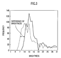
- Fig. 3 shows an example of the prepared histogram.
- a curve in solid line expresses a brightness histogram of the left image and a curve in broken line expresses a brightness histogram of the right image.
- step S2 a lateral deviation between the respective histograms of the left and right images is obtained.
- miscellaneous methods are known. For example, while shifting one of the left and right histogram curves in a direction of the abscissa, the amount of the shifting when the sum of the absolute value of the frequency difference from the other histogram curve is minimal is searched.
- lateral deviation represents a difference of the entire brightness level between the left and right images, that is, a deviation of brightness offset between the left and right images.
- the deviation value of brightness offset be Eb
- the brightness deviation value Eb is defined as "positive" when the left image is brighter than the right image.
- step S3 the brightness deviation value Eb is converted into an a correction amount Do of the clamp value.
- the program goes to S4 where a sum of the current clamp value and the correction amount Do is outputted to the clamp circuit 7 on the left image side and the process finishes.
- the clamp level with respect to the output of the amplifier 5 is corrected so as to delete the deviation of the brightness offset between left and right images and the brightness level A/D converted in the A/D converter 9 of the left image is adjusted to the same level as the brightness level A/D converted in the A/D converter 8 of the right image.
- the current clamp value of the clamp circuit 6 on the right image side is reduced by the correcting value Do in place of changing the clamp value of the clamp circuit 7 on the left image side.
- the clamp level of the right image is lowered and the deviation of the brightness offset between the left and right images is adjusted.
- the deviation of the brightness offset between the paired images of the stereoscopic camera can be automatically deleted and the accuracy of stereoscopic image processing can be enhanced.
- the effect of the invention is large particularly in dark situations such as nights.
- the pair of original left and right images stored in the image data memory 11 and the parallax data stored in a parallax data memory 13 are inputted to an image processing apparatus 14a and are subjected to miscellaneous image processings therein.
- the image processing apparatus 14a are constituted mainly by a micro computer and other interface circuits, functionally including a recognition processing section 15 in which the position of an own vehicle and surrounding circumstances are recognized based on the original left and right images of the image data memory 11 and on the parallax data of the parallax data memory 13, and a brightness adjusting section 16a in which gains for amplifiers 4a, 5a and the clamp values for the clamp circuits 6, 7 are calculated based on the left and right original image data of the image data memory 11 to adjust the brightness balance of the left and right images.
- the gains of the respective amplifiers 4a, 5a can be varied from outside.
- a first evaluation window is established in one image of the left and right images
- a second evaluation window having a correlation with a brightness characteristic of the first evaluation window is established in the other image of the left and right images
- a plurality of paired samples of an evaluation value representing the magnitude of an overall brightness of the first evaluation window and an evaluation value representing the magnitude of an overall brightness of the second evaluation window are calculated.
- a regression line with respect to the distribution of the paired samples is obtained and the brightness gain and the reference voltage of the black level are corrected simultaneously such that this regression line is a proportional line passing through an origin.
- the brightness adjusting section 16a have two functions as a paired evaluation samples calculating means and a brightness balance adjusting means. Specifically, these means are realized by executing processes shown in Fig.5. Below, the brightness adjusting processing in the brightness adjusting section 16a will be described by reference to Fig. 5.
- left and right original image data are read from the image data memory 11 and a window Wr composed of H pixels laterally x V pixels vertically (for example, 20 pixels x 20 pixels) is cut out at random from the right image.
- This window is referred to as a first evaluation or a right window.
- a window Wl having a highest brightness correlation with the first evaluation window Wr is cut out from the left image.
- This window Wl is referred to as a second evaluation window or a left window.
- the left window Wl having the highest brightness correlation with the right window Wr is determined by a technique disclosed in Toku-Kai 2000-69402 filed by the applicant of the present invention. Since the method of the determination is described in detail in Toku-Kai 2000-69402, only a fundamental method will be described next.
- parallax data of a region corresponding to the right window Wr are read from the parallax data memory 13 and a value having a highest frequency in a histogram of the parallax data or an averaged value of the parallax data is obtained as a parallax representative of the right window Wr.
- the left window Wl having the same size as the right window Wr is established in a position horizontally offset by the representative parallax of the left image. Otherwise, a region having a highest correlation with the right window Wr can be identified in the left image by performing a stereo matching while shifting pixel by pixel on a epipoler line of the left image.
- the program goes from the step S11 to a step S12 where a total sum of the brightness values of the right window Wr, namely, an evaluation value (total brightness) of the right window Wr and a total sum of the brightness values of the left window Wl, namely, an evaluation value (total brightness) of the left window Wl are calculated respectively.
- a pair of the left and right evaluation values (hereinafter, referred to as "paired evaluation samples") are memorized in a memory.
- the program goes to a step S13 where it is checked whether or not these processes of S11, S12 are repeated N times (for example 30 times). In case where numbers of the repetition are smaller than N, the processes of S1, S2 are continued. In case where the number of the repetition reaches N, the program goes to a step S14 where a distribution of the paired evaluation samples memorized in the memory is checked.
- step S14 in case where it is judged that the distribution is biased on a high brightness side or a low brightness side, all N pieces of the paired evaluation samples are deleted and the program returns to the step S11 from which the same processes are done over again. It is judged as follows whether or not the paired evaluation samples are concentrated on the high or low brightness sides.
- the program goes from the step S14 to a step S15 where parameters (gradient a, intercept b) of a regression line when the N paired brightness samples are plotted on a graph of right brightness versus to left brightness are calculated by the least square method for example. Representing right brightness on an abscissa and representing left brightness on an ordinate, further letting left and right brightness be Br, Bl respectively, the regression line is expressed as a formula (1).
- Bl a x Br + b
- a correction amount Do of the clamp value in the clamp circuit 7 for the left image and a correction amount Dg of the gain value in the amplifier 5a for the left image are calculated respectively from the regression line according to the formula (1).
- the constant Co expresses a ratio of an increment of clamp value to an increment of brightness ( ⁇ clamp value / ⁇ brightness) and the constant Cg expresses a ratio of an increment of gain value to an increment of brightness ( ⁇ gain / ⁇ brightness in the vicinity of a maximum brightness); 255 is a maximum value of brightness.
- the program goes to a step S17 where an indicating value representing a sum of the present gain value and the correction amount Dg and an indicating value representing a sum of the present clamp value and the correction amount Do are outputted to the amplifier 5a and the clamp circuit 7 for the left image, respectively and the program ends.
- the gain of the amplifier 5a for the left image and also the clamp value of the clamp circuit 7 for the left image are corrected so as to delete the difference of brightness and the deviation of brightness offset between the left and right images. That is, the brightness gain of the left image after passing through the amplifier 5a is adjusted so as to coincide with the brightness gain of the right image after passing through the amplifier 4a. Further, the brightness level A/D converted in the A/D converter 9 after passing through the clamp circuit 7 of the left image is adjusted to the same level as the brightness level A/D converted in the A/D converter 8 after passing through the clamp circuit 6 of the right image.
- the gain and clamp values on the right image side may be changed by reducing the indicating values from the respective present values to adjust the brightness balance of the left and right images.
- this second embodiment it is possible to automatically and simultaneously delete the difference of brightness gain due to the dispersion of outputs of two cameras constituting the stereoscopic camera and the deviation of brightness offset due to the dispersion of direct current signal levels between the paired images and whereby the brightness of respective positions imaging an identical object can be equalized between the left and right images.
- more correct stereo matchings becomes available, these raising the accuracy of detecting distances and enabling more accurate image recognitions.
Landscapes
- Engineering & Computer Science (AREA)
- Multimedia (AREA)
- Signal Processing (AREA)
- Testing, Inspecting, Measuring Of Stereoscopic Televisions And Televisions (AREA)
- Stereoscopic And Panoramic Photography (AREA)
- Measurement Of Optical Distance (AREA)
Abstract
Description
and a total sum of the brightness values of the left window Wl, namely, an evaluation value (total brightness) of the left window Wl are calculated respectively. Then, a pair of the left and right evaluation values (hereinafter, referred to as "paired evaluation samples") are memorized in a memory. Next, the program goes to a step S13 where it is checked whether or not these processes of S11, S12 are repeated N times (for example 30 times). In case
where numbers of the repetition are smaller than N, the processes of S1, S2 are continued. In case where the number of the repetition reaches N, the program goes to a step S14 where a distribution of the paired evaluation samples memorized in the memory is checked.
Claims (7)
- An adjusting apparatus for adjusting a brightness balance between a pair of images taken by a stereoscopic camera (1), comprising:offset level adjusting means (16) for adjusting a brightness offset amount of at least one of the pair of images; andoffset deviation adjusting means (10-14) for adjusting a deviation of the brightness offset between the pair of images by correcting the brightness offset amount based on a difference of brightness distribution between the pair of images.
- The apparatus according to claim 1,
wherein the offset deviation adjusting means (10-14) includes means for preparing a brightness histogram for each of the pair of images and for transforming a deviation of brightness on the brightness histogram between the pair of images into a correction amount of the brightness offset amount. - The apparatus according to claim 1 or 2,
wherein the brightness offset amount is adjusted by adjusting a reference voltage (6, 7) of a black level. - An adjusting apparatus for adjusting a brightness balance between a pair of images taken by a stereoscopic camera (1), comprising:gain adjusting means (4a, 5a) for adjusting a brightness gain of the pair of images;offset level adjusting means (16a) for adjusting a brightness offset amount of at least one of the pair of images;first evaluation window establishing means (14a) for establishing a first evaluation window in one of the images;second evaluation window establishing means (14a) for establishing a second evaluation window having a brightness correlation with the first evaluation window in the other image;paired evaluation samples calculating means (14a) for calculating a plurality of paired evaluation samples of an evaluation value representing a magnitude of an overall brightness of the first evaluation window and an evaluation value representing a magnitude of an overall brightness of the second evaluation window; andbrightness balance adjusting means (16a) for adjusting a brightness balance between the images by correcting the brightness gain (4a, 5a) and the brightness offset amount (6, 7) so as to reduce a difference between the evaluation values.
- The apparatus according to claim 4,
wherein the brightness balance adjusting means (16a) include means for obtaining a regression line based on a distribution of the paired evaluation samples and for correcting the brightness gain and the brightness offset amount such that the regression line is a proportional line having a gradient of 1 and passing through an origin. - The apparatus according to claim 4 or 5,
wherein the brightness offset is adjusted by adjusting a reference voltage (6, 7) of a black level. - The apparatus according to any of claims 4 to 6,
wherein the gain adjusting means (4a, 5a) include an amplifier and the brightness gain is adjusted by adjusting an amplification degree of the amplifier for amplifying a voltage of the image signal.
Applications Claiming Priority (4)
| Application Number | Priority Date | Filing Date | Title |
|---|---|---|---|
| JP2001354994 | 2001-11-20 | ||
| JP2001354995A JP3833930B2 (en) | 2001-11-20 | 2001-11-20 | Stereo camera adjustment device |
| JP2001354994A JP2003158751A (en) | 2001-11-20 | 2001-11-20 | Stereo camera adjustment device |
| JP2001354995 | 2001-11-20 |
Publications (2)
| Publication Number | Publication Date |
|---|---|
| EP1313328A2 true EP1313328A2 (en) | 2003-05-21 |
| EP1313328A3 EP1313328A3 (en) | 2004-02-04 |
Family
ID=26624620
Family Applications (1)
| Application Number | Title | Priority Date | Filing Date |
|---|---|---|---|
| EP02025640A Withdrawn EP1313328A3 (en) | 2001-11-20 | 2002-11-19 | Stereoscopic camera with luminance difference adjustement |
Country Status (2)
| Country | Link |
|---|---|
| US (1) | US7162074B2 (en) |
| EP (1) | EP1313328A3 (en) |
Cited By (4)
| Publication number | Priority date | Publication date | Assignee | Title |
|---|---|---|---|---|
| EP1791371A2 (en) | 2005-11-28 | 2007-05-30 | Samsung Electronics Co., Ltd. | Apparatus and method for processing 3D video signal |
| US7529406B2 (en) | 2004-05-07 | 2009-05-05 | Quanta Computer Inc. | High speed and high accuracy image adjusting apparatus and method thereof |
| GB2481664A (en) * | 2010-06-22 | 2012-01-04 | Lg Display Co Ltd | Frame data modulation for reducing luminance variations in stereoscopic displays |
| CN103248910A (en) * | 2012-02-09 | 2013-08-14 | 三星电子株式会社 | Three-dimensional imaging system and image reproducing method thereof |
Families Citing this family (27)
| Publication number | Priority date | Publication date | Assignee | Title |
|---|---|---|---|---|
| US7055363B2 (en) * | 2004-02-11 | 2006-06-06 | Acushnet Company | Method of calibrating a detector and calibration sphere for the same |
| US7170592B2 (en) | 2004-03-10 | 2007-01-30 | Acushnet Company | Method of inspecting a sphere without orienting the sphere |
| US7972221B2 (en) | 2004-03-10 | 2011-07-05 | Acushnet Company | Method of spherical object orientation and orienter for the same |
| JP4578294B2 (en) * | 2005-03-18 | 2010-11-10 | 株式会社エヌ・ティ・ティ・データ三洋システム | Stereoscopic image display device, stereoscopic image display method, and computer program |
| US7773127B2 (en) * | 2006-10-13 | 2010-08-10 | Apple Inc. | System and method for RAW image processing |
| US7893975B2 (en) * | 2006-10-13 | 2011-02-22 | Apple Inc. | System and method for processing images using predetermined tone reproduction curves |
| US7835569B2 (en) * | 2006-10-13 | 2010-11-16 | Apple Inc. | System and method for raw image processing using conversion matrix interpolated from predetermined camera characterization matrices |
| JP4398969B2 (en) * | 2006-11-07 | 2010-01-13 | 富士フイルム株式会社 | Multi-view photographing apparatus, exposure setting method and program in multi-view photographing apparatus |
| US20080200840A1 (en) * | 2007-02-16 | 2008-08-21 | Jose Gerarado Tamez-Pena | Structural quantification of cartilage changes using statistical parametric mapping |
| JP4897593B2 (en) * | 2007-07-09 | 2012-03-14 | 富士フイルム株式会社 | Compound eye photographing apparatus and adjustment method thereof |
| JPWO2010035443A1 (en) * | 2008-09-26 | 2012-02-16 | パナソニック株式会社 | Video signal processing apparatus and video signal processing method |
| US8768938B2 (en) | 2009-06-25 | 2014-07-01 | Hewlett-Packard Development Company, L.P. | Histogram processing by trend and pattern removal |
| KR101690743B1 (en) * | 2009-07-07 | 2016-12-28 | 톰슨 라이센싱 | Method and system for brightness correction for three-dimensional (3d) projection |
| JP5669599B2 (en) * | 2010-05-14 | 2015-02-12 | キヤノン株式会社 | Image processing apparatus and control method thereof |
| JP5623156B2 (en) * | 2010-06-29 | 2014-11-12 | キヤノン株式会社 | Image processing apparatus and control method thereof |
| US9350982B2 (en) * | 2010-07-22 | 2016-05-24 | Seiko Epson Corporation | Image display device, image supply device, and image processing method with brightness expanding processing for improved contrast sensitivity in a 3D image |
| WO2012032778A1 (en) | 2010-09-08 | 2012-03-15 | パナソニック株式会社 | Three-dimensional image processing apparatus, three-dimensional image-pickup apparatus, three-dimensional image-pickup method, and program |
| KR101232086B1 (en) * | 2010-10-08 | 2013-02-08 | 엘지디스플레이 주식회사 | Liquid crystal display and local dimming control method of thereof |
| US8687914B2 (en) * | 2010-10-13 | 2014-04-01 | Ability Enterprise Co., Ltd. | Method of producing an image |
| US9307227B2 (en) * | 2011-02-24 | 2016-04-05 | Tektronix, Inc. | Stereoscopic image registration and color balance evaluation display |
| KR101207343B1 (en) * | 2012-08-30 | 2012-12-04 | 재단법인대구경북과학기술원 | Method, apparatus, and stereo camera for controlling image lightness |
| WO2014038408A1 (en) * | 2012-09-06 | 2014-03-13 | ソニー株式会社 | Information processing device, information processing method, and program |
| JP5843751B2 (en) * | 2012-12-27 | 2016-01-13 | 株式会社ソニー・コンピュータエンタテインメント | Information processing apparatus, information processing system, and information processing method |
| WO2016051981A1 (en) | 2014-09-30 | 2016-04-07 | 日立オートモティブシステムズ株式会社 | Vehicle-mounted image recognition device |
| US9390487B2 (en) * | 2014-10-20 | 2016-07-12 | Microsoft Technology Licensing, Llc | Scene exposure auto-compensation for differential image comparisons |
| CN108924530A (en) * | 2017-03-31 | 2018-11-30 | 深圳市易快来科技股份有限公司 | A kind of 3D shoots method, apparatus and the mobile terminal of abnormal image correction |
| CN110971889A (en) * | 2018-09-30 | 2020-04-07 | 华为技术有限公司 | A method, camera device and terminal for acquiring depth image |
Family Cites Families (8)
| Publication number | Priority date | Publication date | Assignee | Title |
|---|---|---|---|---|
| JPH0750856A (en) | 1993-08-06 | 1995-02-21 | Fujitsu Ltd | Level correction circuit for multi-view stereoscopic images |
| US6111596A (en) * | 1995-12-29 | 2000-08-29 | Lucent Technologies Inc. | Gain and offset correction for efficient stereoscopic coding and improved display |
| KR100258982B1 (en) * | 1997-12-02 | 2000-06-15 | 윤종용 | Screen brightness control portion of monitor |
| JP4021026B2 (en) | 1998-01-29 | 2007-12-12 | 富士重工業株式会社 | Stereo image processing system |
| JP4384747B2 (en) | 1998-08-24 | 2009-12-16 | マグナチップセミコンダクター有限会社 | Black level adjustment device for video camera |
| JP2958462B1 (en) | 1998-10-01 | 1999-10-06 | 工業技術院長 | Method and apparatus for correcting luminance of stereo image |
| JP3830689B2 (en) | 1999-05-25 | 2006-10-04 | 三菱電機株式会社 | Stereo camera |
| JP3587506B2 (en) | 1999-08-30 | 2004-11-10 | 富士重工業株式会社 | Stereo camera adjustment device |
-
2002
- 2002-11-18 US US10/298,356 patent/US7162074B2/en not_active Expired - Fee Related
- 2002-11-19 EP EP02025640A patent/EP1313328A3/en not_active Withdrawn
Cited By (7)
| Publication number | Priority date | Publication date | Assignee | Title |
|---|---|---|---|---|
| US7529406B2 (en) | 2004-05-07 | 2009-05-05 | Quanta Computer Inc. | High speed and high accuracy image adjusting apparatus and method thereof |
| EP1791371A2 (en) | 2005-11-28 | 2007-05-30 | Samsung Electronics Co., Ltd. | Apparatus and method for processing 3D video signal |
| EP1791371A3 (en) * | 2005-11-28 | 2010-07-07 | Samsung Electronics Co., Ltd. | Apparatus and method for processing 3D video signal |
| US7944481B2 (en) | 2005-11-28 | 2011-05-17 | Samsung Electronics Co., Ltd. | Apparatus and method for processing 3D video signal |
| GB2481664A (en) * | 2010-06-22 | 2012-01-04 | Lg Display Co Ltd | Frame data modulation for reducing luminance variations in stereoscopic displays |
| GB2481664B (en) * | 2010-06-22 | 2012-07-04 | Lg Display Co Ltd | Data modulation method and liquid crystal display device using the same |
| CN103248910A (en) * | 2012-02-09 | 2013-08-14 | 三星电子株式会社 | Three-dimensional imaging system and image reproducing method thereof |
Also Published As
| Publication number | Publication date |
|---|---|
| EP1313328A3 (en) | 2004-02-04 |
| US20030095178A1 (en) | 2003-05-22 |
| US7162074B2 (en) | 2007-01-09 |
Similar Documents
| Publication | Publication Date | Title |
|---|---|---|
| US7162074B2 (en) | Adjusting apparatus for stereoscopic camera | |
| US6987534B1 (en) | Brightness adjusting apparatus for stereoscopic camera | |
| US7092015B1 (en) | Apparatus and method for stereo matching and method of calculating an infinite distance corresponding point | |
| US6552742B1 (en) | Positional deviation adjusting apparatus of stereo image | |
| US6381360B1 (en) | Apparatus and method for stereoscopic image processing | |
| US7139424B2 (en) | Stereoscopic image characteristics examination system | |
| KR100942925B1 (en) | Stereo Vision System and Its Control Method | |
| US8995753B2 (en) | Stereo distance measurement apparatus and stereo distance measurement method | |
| US6985619B1 (en) | Distance correcting apparatus of surroundings monitoring system and vanishing point correcting apparatus thereof | |
| KR100938167B1 (en) | Ambient Light Correction Device, Ambient Light Correction Method, Electronic Information Equipment, Control Program, and Readable Recording Media | |
| US10455149B2 (en) | Image processing apparatus, image processing apparatus control method, image pickup apparatus, and image pickup apparatus control method | |
| EP0957642A2 (en) | Image correction apparatus for stereo camera | |
| US6396946B1 (en) | Stereoscopic image processing apparatus | |
| US8199202B2 (en) | Image processing device, storage medium storing image processing program, and image pickup apparatus | |
| JP2000341719A (en) | Stereo camera | |
| JP3833930B2 (en) | Stereo camera adjustment device | |
| JP2003158751A (en) | Stereo camera adjustment device | |
| KR101439013B1 (en) | Apparatus and method for stereo image processing | |
| CN113364935B (en) | Camera lens shadow compensation method, device, equipment and camera equipment | |
| CN119251109A (en) | An adaptive non-uniformity correction method for ultra-large field of view infrared images | |
| KR102514200B1 (en) | Automatic method of calibrating camera parameter for improving the quality of a specific area in the image | |
| WO2023074452A1 (en) | Camera device and method for controlling camera device | |
| JP4435525B2 (en) | Stereo image processing device | |
| EP2727077A1 (en) | A system and method for resolution enhancement | |
| JP4539400B2 (en) | Stereo camera correction method and stereo camera correction device |
Legal Events
| Date | Code | Title | Description |
|---|---|---|---|
| PUAI | Public reference made under article 153(3) epc to a published international application that has entered the european phase |
Free format text: ORIGINAL CODE: 0009012 |
|
| AK | Designated contracting states |
Designated state(s): AT BE BG CH CY CZ DE DK EE ES FI FR GB GR IE IT LI LU MC NL PT SE SK TR |
|
| AX | Request for extension of the european patent |
Extension state: AL LT LV MK RO SI |
|
| PUAL | Search report despatched |
Free format text: ORIGINAL CODE: 0009013 |
|
| AK | Designated contracting states |
Kind code of ref document: A3 Designated state(s): AT BE BG CH CY CZ DE DK EE ES FI FR GB GR IE IT LI LU MC NL PT SE SK TR |
|
| AX | Request for extension of the european patent |
Extension state: AL LT LV MK RO SI |
|
| RIC1 | Information provided on ipc code assigned before grant |
Ipc: 7G 01S 11/12 B Ipc: 7H 04N 13/00 A |
|
| 17P | Request for examination filed |
Effective date: 20040407 |
|
| AKX | Designation fees paid |
Designated state(s): DE FR GB |
|
| STAA | Information on the status of an ep patent application or granted ep patent |
Free format text: STATUS: THE APPLICATION HAS BEEN WITHDRAWN |
|
| 18W | Application withdrawn |
Effective date: 20100825 |