EP1313241A2 - SONET/SDH data link administration and management - Google Patents
SONET/SDH data link administration and management Download PDFInfo
- Publication number
- EP1313241A2 EP1313241A2 EP02292796A EP02292796A EP1313241A2 EP 1313241 A2 EP1313241 A2 EP 1313241A2 EP 02292796 A EP02292796 A EP 02292796A EP 02292796 A EP02292796 A EP 02292796A EP 1313241 A2 EP1313241 A2 EP 1313241A2
- Authority
- EP
- European Patent Office
- Prior art keywords
- data link
- data
- port
- unchannelized
- connectivity information
- Prior art date
- Legal status (The legal status is an assumption and is not a legal conclusion. Google has not performed a legal analysis and makes no representation as to the accuracy of the status listed.)
- Granted
Links
- RGNPBRKPHBKNKX-UHFFFAOYSA-N hexaflumuron Chemical compound C1=C(Cl)C(OC(F)(F)C(F)F)=C(Cl)C=C1NC(=O)NC(=O)C1=C(F)C=CC=C1F RGNPBRKPHBKNKX-UHFFFAOYSA-N 0.000 title 1
- 230000003287 optical effect Effects 0.000 claims abstract description 12
- 230000006855 networking Effects 0.000 claims abstract description 3
- 238000000034 method Methods 0.000 claims description 50
- 230000001360 synchronised effect Effects 0.000 claims description 7
- 238000012544 monitoring process Methods 0.000 abstract description 2
- 238000010586 diagram Methods 0.000 description 17
- 238000005516 engineering process Methods 0.000 description 16
- 230000008569 process Effects 0.000 description 16
- 230000005540 biological transmission Effects 0.000 description 4
- 238000012546 transfer Methods 0.000 description 4
- 230000005012 migration Effects 0.000 description 3
- 238000013508 migration Methods 0.000 description 3
- 230000004044 response Effects 0.000 description 3
- RYGMFSIKBFXOCR-UHFFFAOYSA-N Copper Chemical compound [Cu] RYGMFSIKBFXOCR-UHFFFAOYSA-N 0.000 description 2
- 229910052802 copper Inorganic materials 0.000 description 2
- 239000010949 copper Substances 0.000 description 2
- 238000000638 solvent extraction Methods 0.000 description 2
- 101100478719 Postia placenta (strain ATCC 44394 / Madison 698-R) STS-18 gene Proteins 0.000 description 1
- 102100040338 Ubiquitin-associated and SH3 domain-containing protein B Human genes 0.000 description 1
- 101710143616 Ubiquitin-associated and SH3 domain-containing protein B Proteins 0.000 description 1
- 230000004913 activation Effects 0.000 description 1
- 230000002776 aggregation Effects 0.000 description 1
- 238000004220 aggregation Methods 0.000 description 1
- 239000000835 fiber Substances 0.000 description 1
- 238000012423 maintenance Methods 0.000 description 1
- 238000012545 processing Methods 0.000 description 1
- 238000011084 recovery Methods 0.000 description 1
Images


Classifications
-
- H—ELECTRICITY
- H04—ELECTRIC COMMUNICATION TECHNIQUE
- H04L—TRANSMISSION OF DIGITAL INFORMATION, e.g. TELEGRAPHIC COMMUNICATION
- H04L41/00—Arrangements for maintenance, administration or management of data switching networks, e.g. of packet switching networks
- H04L41/32—Specific management aspects for broadband networks
-
- H—ELECTRICITY
- H04—ELECTRIC COMMUNICATION TECHNIQUE
- H04J—MULTIPLEX COMMUNICATION
- H04J3/00—Time-division multiplex systems
- H04J3/02—Details
- H04J3/08—Intermediate station arrangements, e.g. for branching, for tapping-off
- H04J3/085—Intermediate station arrangements, e.g. for branching, for tapping-off for ring networks, e.g. SDH/SONET rings, self-healing rings, meashed SDH/SONET networks
-
- H—ELECTRICITY
- H04—ELECTRIC COMMUNICATION TECHNIQUE
- H04J—MULTIPLEX COMMUNICATION
- H04J3/00—Time-division multiplex systems
- H04J3/16—Time-division multiplex systems in which the time allocation to individual channels within a transmission cycle is variable, e.g. to accommodate varying complexity of signals, to vary number of channels transmitted
- H04J3/1605—Fixed allocated frame structures
- H04J3/1611—Synchronous digital hierarchy [SDH] or SONET
- H04J3/1617—Synchronous digital hierarchy [SDH] or SONET carrying packets or ATM cells
-
- H—ELECTRICITY
- H04—ELECTRIC COMMUNICATION TECHNIQUE
- H04J—MULTIPLEX COMMUNICATION
- H04J2203/00—Aspects of optical multiplex systems other than those covered by H04J14/05 and H04J14/07
- H04J2203/0001—Provisions for broadband connections in integrated services digital network using frames of the Optical Transport Network [OTN] or using synchronous transfer mode [STM], e.g. SONET, SDH
- H04J2203/0028—Local loop
- H04J2203/0039—Topology
- H04J2203/0042—Ring
-
- H—ELECTRICITY
- H04—ELECTRIC COMMUNICATION TECHNIQUE
- H04J—MULTIPLEX COMMUNICATION
- H04J2203/00—Aspects of optical multiplex systems other than those covered by H04J14/05 and H04J14/07
- H04J2203/0001—Provisions for broadband connections in integrated services digital network using frames of the Optical Transport Network [OTN] or using synchronous transfer mode [STM], e.g. SONET, SDH
- H04J2203/0057—Operations, administration and maintenance [OAM]
-
- H—ELECTRICITY
- H04—ELECTRIC COMMUNICATION TECHNIQUE
- H04J—MULTIPLEX COMMUNICATION
- H04J2203/00—Aspects of optical multiplex systems other than those covered by H04J14/05 and H04J14/07
- H04J2203/0001—Provisions for broadband connections in integrated services digital network using frames of the Optical Transport Network [OTN] or using synchronous transfer mode [STM], e.g. SONET, SDH
- H04J2203/0064—Admission Control
- H04J2203/0067—Resource management and allocation
-
- H—ELECTRICITY
- H04—ELECTRIC COMMUNICATION TECHNIQUE
- H04J—MULTIPLEX COMMUNICATION
- H04J2203/00—Aspects of optical multiplex systems other than those covered by H04J14/05 and H04J14/07
- H04J2203/0001—Provisions for broadband connections in integrated services digital network using frames of the Optical Transport Network [OTN] or using synchronous transfer mode [STM], e.g. SONET, SDH
- H04J2203/0073—Services, e.g. multimedia, GOS, QOS
- H04J2203/0082—Interaction of SDH with non-ATM protocols
Definitions
- the invention relates to data network provisioning and management, and in particular to methods of administration and management of high capacity data links.
- Synchronous Optical NETwork SONET
- Synchronous Digital Hierarchy SDH
- SONET is the North American version of the standard published by the American National Standards Institute (ANSI).
- SDH is the international version of the standard published by the International Telecommunications Union (ITU).
- SONET/SDH data transport technologies are enabled by SONET/SDH data switching equipment, data transport equipment, interface equipment, etc. each supporting the SONET/SDH transmission protocols.
- SONET/SDH technology was developed and initially used for high capacity data transport in the core of data transport networks and in particular at the physical Layer 1 (ref. Open Systems Interconnection hierarchy -- OSI).
- Physical Layer 1 connectivity is implemented hop-by-hop between data ports. Cables are connected physically (Layer 1) to the ports to convey data therethrough. The conveyance of data includes unidirectional and bi-directional data transfers. Each port has a physical data transport capacity. Data transport capacity hierarchy showing SONET - SDH equivalents.
- a group of Layer 1 data transport capacities are defined for SONET/SDH ports.
- the group of data transport capacities forms a data transport capacity hierarchy known as Optical Carrier Hierarchy (OC) or the Synchronous Transport Mode (STM) capacity hierarchy respectively and is presented in the Table 1.
- OC Optical Carrier Hierarchy
- STM Synchronous Transport Mode
- the ports are referred to as: OC-3/STM-1 ports, OC-48/STM-16 ports, etc.
- SONET technologies and it is understood to include SDH technologies.
- SONET ports are implemented on interface cards. Exemplary configurations include interface cards having: 2 OC-192 ports, 4 OC-48 ports, 8 OC-12 ports, 16 OC-3 ports, etc. SONET ports may also form an integral part of a data network node.
- Data network nodes may have Layer 1 implementations including at least one shelf to receive a plurality of interface cards.
- the connectivity between a node and an interface card is provided via a slot connector.
- Slots are keyed shelf recesses into which physical interface cards are inserted.
- interface cards supporting data transport technologies other than SONET may be connected to a node either to provide distribution side connectivity and/or provide bridging across data transport networks.
- POS Packet-over-SONET
- IP Internet Protocol
- An unpartitioned POS port is known as an unchannelized port.
- the unchannelized configuration of a POS port enables access to the full OC/STM bandwidth thereof.
- the channelization is a Layer 1 logical bandwidth partitioning enabling a more efficient utilization of the raw bandwidth of a POS port.
- Table 2 shows exemplary Layer 1 POS port configurations.
- OSI Data Link Layer 2 connections are setup to convey data traffic between nodes.
- Layer 2 connectivity includes port specifications for both ends of a data connection.
- a data connection having an allocated bandwidth, represents a data link.
- the variety of data link configurations include:
- POS data links tend to be relatively few in number and at the same time tend to have large data transport capacities.
- the relatively small number of POS data links renders a manual provisioning thereof adequate.
- the complexity of POS data link connectivity presented above is balanced by the relatively small number of POS data links required to be maintained and administered.
- POS links necessary to be set-up and maintained increases with the migration of SONET technologies beyond the core of data transport networks as IP packet switching technologies are used to deploy end user services.
- the complexity of the connectivity of POS links therefore introduces a large overhead no longer lending itself to manual provisioning and management thereof.
- the configuration physical Layer 1 complexity of POS ports into a channelized configurations or unchannelized configurations is relevant for POS data link connectivity at set-up.
- the actual physical port configuration once physical and data link connectivity is established, has a lower importance in providing network management solutions.
- TDM Time Division Multiplexed
- T1 ports can also be configured as channelized or unchannelized.
- the current field practice treats these two types of T1 port configurations as being incompatible for physical Layer 1 interconnection purposes.
- Layer 2 data links those provisioned between unchannelized ports as opposed to those provisioned between channels on channelized ports.
- a network management workstation providing an administration and management interface to an analyst is cluttered by the multitude of physical layer SONET devices used in provisioning POS data links.
- Physical layer SONET devices include: physical long haul optical cables, add/drop multiplexers, physical short haul copper links, (optical) interconnects, (optical) switches, aggregation/deaggregation nodes, Wavelength Division Multiplexers (WDM), Dense Wavelength Division Multiplexers (DWDM) etc.
- An object of the present invention is to provide a management and administration system for a Packet over Synchronous Optical Network data network that is concise and comprehensive in order to provide provisioning, administering and managing of POS data connections.
- the invention provides a management and administration system for a Packet over Synchronous Optical Network data network comprising:
- the network management and administration system makes use of connectivity information in establishing and monitoring data links.
- the connectivity information includes data link termination specifications.
- Data link termination specifications include port and channel specifications. Each port may have a channelized or an unchannelized configuration. A virtual channel having a data transport capacity substantially equal to that of a corresponding unchannelized port is defined therefore.
- the advantages include a standardized, concise and comprehensive provisioning and presentation of data links
- the network management and administration system further includes a second body of connectivity information enabling the selection of data link terminations for the establishment of data links in the data network.
- the connectivity information held in the second body of connectivity information specifies data link terminations down to a channel specification.
- the connectivity information regarding data link terminations also specifies ports on which each data link terminates.
- the ports having a channelized or an unchannelized configuration.
- the channel specification for each unchannelized port includes a virtual channel specification associated therewith.
- a method of provisioning a data link in a data networking environment includes a sequence of steps.
- a first and a second data link terminations are selected from a selection group of data link terminations. Specifications of the first and second data link terminations include channel specifications.
- the selected first and second data link terminations are validated with respect to a data transport capacity and a data transport protocol. The validated selections are used in establishing a data link.
- the method further includes steps of updating bodies of connectivity information to keep a record of the established data link.
- the advantages include a standardized, concise and comprehensive provisioning and presentation of data links.
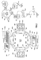
- FIG. 1 is a schematic diagram showing a representation of SONET equipment provisioning data transport services.
- Data transport services are provisioned over a SONET network 100 having a ring topology.
- the invention is not limited to data transport networks having ring topologies.
- SONET technologies can be employed to implement network topologies such as, but not limited to: point-to-point, ring, star, mesh, etc.
- Depicted physical Layer 1 devices include long haul optical cables 102, add/drop multiplexers 104, short haul copper/optical interconnects 106, nodes 108, etc. As it would be apparent to persons of ordinary skill in the art, a myriad of other devices employing SONET technologies may be used without departing from the spirit of the invention.
- the nodes 108 are shown to have channelized ports 110 and unchannelized ports 112. Although only two ports 110 are shown per node 108 to enable easy presentation of relevant concepts, the invention is not limited thereto.
- the north node 108 is shown to have a channelized OC-192 port 110-1 partitioned into 4 OC-48 channels 114, as well as a second channelized OC-192 port 110-2 partitioned into 16 OC-12 channels 114.
- the west node 108 is shown to have two unchannelized OC-48 ports 112-1 and 112-2 while the east node 108 has two unchannelized OC-12 ports 112-1 and 112-2.
- the south node 108 has an OC-48 channelized port 110 partitioned into 4 OC-12 channels 114, and an unchannelized OC-48 port 112-2.
- the label indexes "-#" represent interface card identifiers within respective card shelves of nodes 108; their relevance will be more apparent from the description below with reference to FIG. 2, FIG. 3 and FIG. 5.
- each POS data link originates and terminates on a channel of a POS port. Since POS ports are not necessarily channelized, the invention teaches the virtual channelization of unchannelized POS ports - where each virtual channel has a bandwidth substantially equal to the physical bandwidth of the POS port. For example, the combination of the unchannelized OC-48 port bearing a virtual channel is representative of a channelized OC-48 port having one OC-48 channel.
- a data link record is maintained for established POS data links between data network nodes supporting SONET data transfer technologies.
- the connectivity information held in the data link record is extended to include channel specifications.
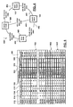
- FIG.2 is a schematic diagram showing a tabular representation of a connectivity information database specifying established POS data links in accordance with an exemplary implementation of the invention.
- data link record table 200 is shown to include row entries 202. Each entry 202 corresponds to an established POS data link in the managed data transport network 100.
- the data link record table 200 is representative of a connectivity database held centrally by a Network Management System (NMS). Alternatively the data link record table 200 may be replicated and maintained by multiple network management entities associated with the data transport network 100.
- NMS Network Management System
- Each data link entry 202 holds a data link identifier 204 and perhaps a data link capacity label 206. Each entry 202 further includes origination 208 and destination 210 connectivity information for the corresponding established data link.
- the origination connectivity information 208 and the destination connectivity information 210 include respectively: an origination/destination node identifier 212 for the corresponding data link end, a shelf designation 214 for an associated interface card whose designation is specified at 216, the interface card being connected to a corresponding slot having a designation 218 on the shelf 214, and a port designation 220 of a port on the interface card 216.
- the connectivity information 208/210 includes a channel specification 224.
- the connectivity information 208/210 includes a virtual channel specification 224.
- the virtual channel specification 224 is shown in FIG. 2, between parentheses for emphasis.
- the connectivity information held in the data link record 200 is not limited to the specifiers shown.
- the connectivity information 208/210 may further include a port type specification 222 for each port 220 detailing whether the port 220 is channelized or unchannelized.
- POS data links include unidirectional links and bi-directional links.
- unidirectional links the direction of the data flow may be inferred from the origination 208 and destination 210 connectivity information.
- entries 202 in the data link record 200 may include an additional specifier holding directionality information. An example of a directionality specifier will be presented below with reference to FIG. 3.
- each entry 202 may specify the type of data traffic conveyed e.g. Voice traffic, POS traffic, etc.
- FIG. 3 is a schematic diagram showing another tabular representation of connectivity information specifying established POS data links in accordance with another exemplary implementation of the invention.
- a data link record table 300 is associated with a corresponding data network node 108 and includes row entries 302. Each entry 302 corresponds to an established POS data link in the managed data transport network 100.
- Each data link entry 302 holds a data link identifier 304 and perhaps a data link capacity label 306. Each entry 302 specifies further connectivity information for the corresponding data link including: a shelf designation 314 for an associated interface card whose designation is specified at 316, the interface card being connected to a corresponding slot having a designation 318 on the shelf 314, and a port designation 320 of a port on the interface card 316.
- the connectivity information further includes a port type specification 322 for each port 320 detailing whether the port 320 is channelized or unchannelized.
- the connectivity information includes a channel specification 324. If the port 320 is unchannelized, the connectivity information includes a virtual channel specification 324.
- the virtual channel specification 324 is show in FIG. 3 between parentheses for emphasis.
- an NMS system inspects each nodal data link record 300 in deriving connectivity information regarding the entire network 100 using data link identifiers 304 to correlate entries 302 between multiple nodal data link records 300.
- Entries 302 may contain other connectivity information including, but not limited to data transfer directionality information 326.
- the invention is not limited to the implementations of the data link records 200 and 300 presented above. Persons of skill in the art would recognize that the data link record 200 can be generated from a plurality of data link records 300 and vice versa.
- the invention also applies to cases in which only partial data link information is available such as data link connectivity information being available only with respect to one termination thereof - for example due to a node failure.
- the missing connectivity information may be regenerated through a discovery process using data link connectivity information synchronization (element synchronization) processes.
- the discovery process may be initiated by higher level protocols such as would otherwise be the case during failure recovery.
- the discovery process may make use of handshaking processes provided by the underlying SONET equipment.
- the discovery process determines: shelf designation, interface card designations, port designations, port configuration, and channel designations for the opposite terminations of the corresponding data links.
- a virtual channel is assigned thereto.
- an NMS system prefferably provides a concise yet comprehensive interface displaying a current state of the data transport network 100 that is easy to understand for an analyst using a simple representation of the network topology.
- the NMS interface shows the connectivity information irrespective of the channelized/unchannelized configuration of POS ports.
- FIG. 4 is a schematic diagram showing a simplified representation of POS data links provided via SONET nodes, in accordance with a preferred implementation of the invention.
- a representation 400 of the data transport network 100 is show to include data network nodes 108 and provisioned data links 402.
- Each one of the data network node 108 is positioned using geographic positional information associated with each data network node 108 or using an algorithm taking into account the type of data transport network (ring, linear, star, mesh, etc.)
- Each data link 402 is shown as a schematic direct connection between the data network nodes 108 associated therewith.
- the data link records 200/300 is parsed to examine the entries 202/302.
- data network node specifications 212/312 are extracted and the corresponding nodes 108 displayed on the interface associated with the NMS system.
- Data links 402 are shown schematically connecting the end nodes 212/312 extracted.
- the schematic representation of each data link 402 may include the data link specifier 204/304 and perhaps the data link capacity 206/306.
- each displayed data link 402 represents a logical data link between data network nodes 108 for it only shows data link terminations as opposed to the corresponding physical data link shown in FIG. 1 - without the intermediary devices via which the physical data link is provisioned.
- the schematic representation 402 may include a traffic type specifier associated with a corresponding service provisioned therethrough such as, but not limited to: Voice, POS, etc.
- An analyst interacting with an NMS system besides being able to inspect a current state of the data transport network 100 may be required to provision data links.
- a channel record is provided to enable selection of data link terminations in provisioning data links.
- FIG. 5 is a schematic diagram showing a tabular representation of connectivity information specifying available data link terminations in accordance with another embodiment of the invention.
- a channel record table representation 500 includes channel entries 502 corresponding to each channel in service.
- the channel record 500 is representative of global connectivity information held either centrally and/or distributed.
- the invention is not limited thereto, nodal channel records may also be maintained, either centrally and/or distributed.
- Each entry 502 specifies connectivity information for a corresponding provisioned channel including but not limited to: a node identifier 512, a shelf designation 514 for an associated interface card whose designation is specified at 516, the interface card being connected to a corresponding slot having a designation 518 on the shelf 514, and a port designation 520 of a port on the interface card 516.
- the connectivity information further includes a port type specification 522 for each port 520 detailing whether the port 520 is channelized or unchannelized.
- the connectivity information includes a channel specification 524. If the port 520 is unchannelized, the connectivity information includes a virtual channel specification 524.
- the virtual channel specification 524 is show in FIG. 5 between parentheses for emphasis.
- the connectivity information held in the channel record 500 is not limited to the specifiers shown.
- a channel capacity specification is shown at 506.
- Channel specification may further include data transfer directionality. An example of a directionality specifier has been presented above with reference to FIG. 3.
- FIG. 6 is a schematic diagram showing process (600) of provisioning a data link in accordance with a preferred embodiment of the invention.
- Data link provisioning the analyst is presented with the information held in the channel record 500 whether in the tabular format shown, a selection list, etc.
- Data link provisioning may include a search function limiting the presented connectivity information by node identifier, capacity, etc.
- the analyst selects 610 at least two entries 502 to establish data links therebetween.
- the channel record entry 502 selection for the establishment of a data link therebetween further includes (620) checking for bandwidth compatibility and the displaying of error messages should an incompatibility exist. In the case in which interface cards supporting other data transmission protocols, the selection also checks whether the same data transmission protocol is supported therebetween.
- an appropriate data link entry 202/302 is created (640) in the maintained data link record(s) 200/300. Subsequently, the NMS system displays (670) the created data link 402.
- the display of the created data link 402 need not necessarily be performed by the data link creation process as the display functionality of the NMS system may be part of another execution thread (as shown).
- the discovery of participating data network nodes 108 in a data transport network and the generation of channel records such as 500 may be provided via a reconciliation process.
- FIG. 7 is a schematic diagram showing a process (700) of node reconciliation in accordance with a preferred embodiment of the invention.
- an NMS system broadcasts a request for each node to signal its presence in a data network domain (710). Upon receipt of each response, the NMS system may display (770) the corresponding node 108 to enable selection thereof in creating data links 402. The display 770 of the detected nodes 108 may be performed as part of a parallel processing thread as shown.
- the query-response process 720 is implemented with the aid of administration and management protocols such as but not limited to a Simple Network Management Protocol (SNMP).
- SNMP Simple Network Management Protocol
- the reconciliation process is not limited to request broadcasting.
- the responses (720) provide a node configuration including as physical devices: shelves, empty slots, configured slots containing interface cards, interface card activation status, interface card port configuration, etc.
- the received node configuration is preferably captured 730 in a hierarchical group of data records including: node records, shelf records, interface card records, port records, etc.
- each port is assumed to have at least one channel associated therewith.
- Channel records (500) are derived 740 from channelized port configurations and channel entries are generated for each unchannelized port specifying the full bandwidth of the port as the bandwidth of a corresponding virtual channel.
Landscapes
- Engineering & Computer Science (AREA)
- Computer Networks & Wireless Communication (AREA)
- Signal Processing (AREA)
- Data Exchanges In Wide-Area Networks (AREA)
Abstract
Description
- The invention relates to data network provisioning and management, and in particular to methods of administration and management of high capacity data links.
- In the field of data transport, Synchronous Optical NETwork (SONET) and Synchronous Digital Hierarchy (SDH) are a set of related standards for synchronous data transmission over fiber optic networks. SONET is the North American version of the standard published by the American National Standards Institute (ANSI). SDH is the international version of the standard published by the International Telecommunications Union (ITU).
- SONET/SDH data transport technologies are enabled by SONET/SDH data switching equipment, data transport equipment, interface equipment, etc. each supporting the SONET/SDH transmission protocols. SONET/SDH technology was developed and initially used for high capacity data transport in the core of data transport networks and in particular at the physical Layer 1 (ref. Open Systems Interconnection hierarchy -- OSI).
-
Physical Layer 1 connectivity is implemented hop-by-hop between data ports. Cables are connected physically (Layer 1) to the ports to convey data therethrough. The conveyance of data includes unidirectional and bi-directional data transfers. Each port has a physical data transport capacity.Data transport capacity hierarchy showing SONET - SDH equivalents. Optical Level Electrical Level Line Rate (Mbps) Payload Rate (Mbps) Overhead Rate (Mbps) SDH Equivalent OC-1 STS-1 51.840 50.112 1.728 - OC-3 STS-3 155.520 150.336 5.184 STM-1 OC-9 STS-9 466.560 451.008 15.552 STM-3 OC-12 STS-12 622.080 601.344 20.736 STM-4 OC-18 STS-18 933.120 902.016 31.104 STM-6 OC-24 STS-24 1244.160 1202.688 41.472 STM-8 OC-36 STS-36 1866.240 1804.032 62.208 STM-12 OC-48 STS-48 2488.320 2405.376 82.944 STM-16 OC-96 STS-96 4976.640 4810.752 165.888 STM-32 OC-192 STS-192 9953.280 9621.504 331.776 STM-64 - A group of
Layer 1 data transport capacities are defined for SONET/SDH ports. The group of data transport capacities forms a data transport capacity hierarchy known as Optical Carrier Hierarchy (OC) or the Synchronous Transport Mode (STM) capacity hierarchy respectively and is presented in the Table 1. Correspondingly, the ports are referred to as: OC-3/STM-1 ports, OC-48/STM-16 ports, etc. For the remainder of this presentation, reference will only be made to SONET technologies and it is understood to include SDH technologies. - Typically SONET ports are implemented on interface cards. Exemplary configurations include interface cards having: 2 OC-192 ports, 4 OC-48 ports, 8 OC-12 ports, 16 OC-3 ports, etc. SONET ports may also form an integral part of a data network node.
- Data network nodes (data switching equipment, data transport equipment, etc.) may have
Layer 1 implementations including at least one shelf to receive a plurality of interface cards. The connectivity between a node and an interface card is provided via a slot connector. Slots are keyed shelf recesses into which physical interface cards are inserted. Typically there is a one-to-one correspondence between slots and slot connectors while no implied one-to-oneExemplary port configurations. Port Type Partitioning OC-192 unchannelized - none - channelized 1 x OC-192 channel 4 x OC-48 channels 16 x OC-12 channels 64 x OC-3 channels OC-48 unchannelized - none - channelized 1 x OC-48 channel 4 x OC-12 channels 16 x OC-3 channels OC-12 unchannelized - none - channelized 1 x OC-12 channel 4 x OC-3 channels OC-3 unchannelized - none - etc. - Typically a variety of interface cards supporting data transport technologies other than SONET may be connected to a node either to provide distribution side connectivity and/or provide bridging across data transport networks.
- Recently however, the bandwidth demand for data transport in the edge and/or access portions of data transport networks has increased such that the use of SONET technologies has extended beyond the core of data transport networks for which SONET technologies were initially designed.
- The migration of SONET technology beyond the core of data transport networks is paralleled by Packet-over-SONET (POS) technologies which are being developed to enable SONET data network nodes to convey Internet Protocol (IP) packets directly over SONET frames. A SONET port enabling the conveyance of IP data traffic is known as a POS port. SONET data links conveying IP data traffic are know as POS links.
- In order to address data service specific bandwidth requirements, it is common for the raw bandwidth of a POS port to be partitioned. An unpartitioned POS port is known as an unchannelized port. The unchannelized configuration of a POS port enables access to the full OC/STM bandwidth thereof. The channelization is a
Layer 1 logical bandwidth partitioning enabling a more efficient utilization of the raw bandwidth of a POS port. Table 2 showsexemplary Layer 1 POS port configurations. - OSI
Data Link Layer 2 connections are setup to convey data traffic between nodes. At the core,Layer 2 connectivity includes port specifications for both ends of a data connection. A data connection having an allocated bandwidth, represents a data link. The variety of data link configurations include: - POS data links between two channelized POS ports, each end of each POS data link being associated with a channel on a corresponding channelized POS port; and
- POS data links between two unchannelized POS ports, each end of each POS data link being associated with a corresponding unchannelized physical POS port.
- Since
Layer 1 physical connectivity is made between ports via port connectors, a hybrid type of connectivity including - POS data links between a corresponding unchannelized POS physical port at one end and a corresponding channel on a channelized POS port at the other end.
- The provisioning of data transport over SONET technologies in a data transport network requires the establishment of POS data links. For network core data transport provisioning, the POS data links tend to be relatively few in number and at the same time tend to have large data transport capacities. The relatively small number of POS data links renders a manual provisioning thereof adequate. The complexity of POS data link connectivity presented above is balanced by the relatively small number of POS data links required to be maintained and administered.
- The number of POS links necessary to be set-up and maintained increases with the migration of SONET technologies beyond the core of data transport networks as IP packet switching technologies are used to deploy end user services. The complexity of the connectivity of POS links therefore introduces a large overhead no longer lending itself to manual provisioning and management thereof.
- Further, the configuration
physical Layer 1 complexity of POS ports into a channelized configurations or unchannelized configurations is relevant for POS data link connectivity at set-up. However, as it pertains to data network administration and management the actual physical port configuration, once physical and data link connectivity is established, has a lower importance in providing network management solutions. - Prior practice in data transport provisioning includes the management of Time Division Multiplexed (TDM) links and particularly what are known as T1 connections. Correspondingly, T1 ports can also be configured as channelized or unchannelized. The current field practice treats these two types of T1 port configurations as being incompatible for
physical Layer 1 interconnection purposes. A distinction is made betweenLayer 2 data links: those provisioned between unchannelized ports as opposed to those provisioned between channels on channelized ports. - In providing network management solutions, the migration of SONET technologies beyond the core utilizes an increased number of intermediary SONET physical layer data transport devices. A network management workstation providing an administration and management interface to an analyst is cluttered by the multitude of physical layer SONET devices used in provisioning POS data links. Physical layer SONET devices include: physical long haul optical cables, add/drop multiplexers, physical short haul copper links, (optical) interconnects, (optical) switches, aggregation/deaggregation nodes, Wavelength Division Multiplexers (WDM), Dense Wavelength Division Multiplexers (DWDM) etc.
- There is a need to solve the above mentioned issues.
- An object of the present invention is to provide a management and administration system for a Packet over Synchronous Optical Network data network that is concise and comprehensive in order to provide provisioning, administering and managing of POS data connections.
- More precisely, the invention provides a management and administration system for a Packet over Synchronous Optical Network data network comprising:
- a first body of data link connectivity information holding connectivity information for a plurality of data links established in the associated data network, the connectivity information specifying data link terminations including channel specifications; and
- a display interface showing a current state of the data network including established data links wherein the connectivity information regarding data link terminations also specifies ports on which each data link of the plurality of data links terminates, the ports having a one of a channelized and unchannelized configuration, the channel specification for each unchannelized port including a virtual channel specification associated therewith.
-
- Thus, the network management and administration system makes use of connectivity information in establishing and monitoring data links. The connectivity information includes data link termination specifications. Data link termination specifications include port and channel specifications. Each port may have a channelized or an unchannelized configuration. A virtual channel having a data transport capacity substantially equal to that of a corresponding unchannelized port is defined therefore. The advantages include a standardized, concise and comprehensive provisioning and presentation of data links
- In accordance with a further aspect of the invention, the network management and administration system further includes a second body of connectivity information enabling the selection of data link terminations for the establishment of data links in the data network. The connectivity information held in the second body of connectivity information specifies data link terminations down to a channel specification. The connectivity information regarding data link terminations also specifies ports on which each data link terminates. The ports having a channelized or an unchannelized configuration. The channel specification for each unchannelized port includes a virtual channel specification associated therewith.
- In accordance with a further aspect of the invention, a method of provisioning a data link in a data networking environment is provided. The method includes a sequence of steps. A first and a second data link terminations are selected from a selection group of data link terminations. Specifications of the first and second data link terminations include channel specifications. The selected first and second data link terminations are validated with respect to a data transport capacity and a data transport protocol. The validated selections are used in establishing a data link.
- In accordance with a yet another aspect of the invention, the method further includes steps of updating bodies of connectivity information to keep a record of the established data link.
- The advantages include a standardized, concise and comprehensive provisioning and presentation of data links.
- The features and advantages of the invention will become more apparent from the following detailed description of the preferred embodiments with reference to the attached diagrams wherein:
- FIG. 1 shows a schematic diagram showing a representation of SONET equipment provisioning data transport services;
- FIG. 2 shows a schematic diagram showing a tabular representation of a connectivity information database specifying established POS data links in accordance with an exemplary implementation of the invention;
- FIG. 3 shows a schematic diagram showing another tabular representation of connectivity information specifying established POS data links in accordance with another exemplary implementation of the invention;
- FIG. 4 shows a schematic diagram showing a simplified representation of POS data links provisioned via SONET nodes, in accordance with a preferred implementation of the invention;
- FIG. 5 shows a schematic diagram showing a tabular representation of connectivity information specifying available data link terminations in accordance with another embodiment of the invention;
- FIG. 6 shows a schematic diagram showing process (600) of provisioning a data link in accordance with a preferred embodiment of the invention; and
- FIG. 7 shows a schematic diagram showing a process (700) of node reconciliation in accordance with a preferred embodiment of the invention.
-
- It will be noted that in the attached diagrams like features bear similar labels.
- FIG. 1 is a schematic diagram showing a representation of SONET equipment provisioning data transport services.
- Data transport services are provisioned over a
SONET network 100 having a ring topology. The invention is not limited to data transport networks having ring topologies. SONET technologies can be employed to implement network topologies such as, but not limited to: point-to-point, ring, star, mesh, etc. - Depicted
physical Layer 1 devices include long hauloptical cables 102, add/drop multiplexers 104, short haul copper/optical interconnects 106,nodes 108, etc. As it would be apparent to persons of ordinary skill in the art, a myriad of other devices employing SONET technologies may be used without departing from the spirit of the invention. - The
nodes 108 are shown to have channelized ports 110 and unchannelized ports 112. Although only two ports 110 are shown pernode 108 to enable easy presentation of relevant concepts, the invention is not limited thereto. A high level view of thedata transport network 100 presented on the right, shows the ports 110/112 implemented on interface cards (either integrally or in combination), each card being installed in a shelf.Node 108 designs having multiple shelves exist and the invention applies equally thereto. An implementation of anode 108 having integral ports 110/112 is also shown. - The
north node 108 is shown to have a channelized OC-192 port 110-1 partitioned into 4 OC-48channels 114, as well as a second channelized OC-192 port 110-2 partitioned into 16 OC-12channels 114. Thewest node 108 is shown to have two unchannelized OC-48 ports 112-1 and 112-2 while theeast node 108 has two unchannelized OC-12 ports 112-1 and 112-2. Thesouth node 108 has an OC-48 channelized port 110 partitioned into 4 OC-12channels 114, and an unchannelized OC-48 port 112-2. The label indexes "-#" represent interface card identifiers within respective card shelves ofnodes 108; their relevance will be more apparent from the description below with reference to FIG. 2, FIG. 3 and FIG. 5. - Also shown in the diagram are established
POS data links nodes 108. - As mentioned above, general knowledge in the art teaches the establishment of
Layer 2 POS data links between POS ports. The analyst is required to have knowledge the configuration of each POS port whether channelized 110 or unchannelized 112. - In accordance with a preferred embodiment of the invention, each POS data link originates and terminates on a channel of a POS port. Since POS ports are not necessarily channelized, the invention teaches the virtual channelization of unchannelized POS ports - where each virtual channel has a bandwidth substantially equal to the physical bandwidth of the POS port. For example, the combination of the unchannelized OC-48 port bearing a virtual channel is representative of a channelized OC-48 port having one OC-48 channel.
- In accordance with the preferred embodiment of the invention, a data link record is maintained for established POS data links between data network nodes supporting SONET data transfer technologies.
- In accordance with the preferred embodiment of the invention, the connectivity information held in the data link record is extended to include channel specifications.
- FIG.2 is a schematic diagram showing a tabular representation of a connectivity information database specifying established POS data links in accordance with an exemplary implementation of the invention.
- In accordance with a preferred implementation of the invention, data link record table 200 is shown to include
row entries 202. Eachentry 202 corresponds to an established POS data link in the manageddata transport network 100. The data link record table 200 is representative of a connectivity database held centrally by a Network Management System (NMS). Alternatively the data link record table 200 may be replicated and maintained by multiple network management entities associated with thedata transport network 100. - Each
data link entry 202 holds adata link identifier 204 and perhaps a datalink capacity label 206. Eachentry 202 further includesorigination 208 anddestination 210 connectivity information for the corresponding established data link. - The
origination connectivity information 208 and thedestination connectivity information 210 include respectively: an origination/destination node identifier 212 for the corresponding data link end, ashelf designation 214 for an associated interface card whose designation is specified at 216, the interface card being connected to a corresponding slot having adesignation 218 on theshelf 214, and aport designation 220 of a port on theinterface card 216. - If the
port 220 is channelized, theconnectivity information 208/210 includes achannel specification 224. - In accordance with the invention, if the
port 220 is unchannelized, theconnectivity information 208/210 includes avirtual channel specification 224. Thevirtual channel specification 224 is shown in FIG. 2, between parentheses for emphasis. - The connectivity information held in the
data link record 200 is not limited to the specifiers shown. In accordance with an exemplary implementation of the invention, theconnectivity information 208/210 may further include aport type specification 222 for eachport 220 detailing whether theport 220 is channelized or unchannelized. - POS data links include unidirectional links and bi-directional links. For unidirectional links, the direction of the data flow may be inferred from the
origination 208 anddestination 210 connectivity information. In accordance with another exemplary implementation of the invention,entries 202 in thedata link record 200 may include an additional specifier holding directionality information. An example of a directionality specifier will be presented below with reference to FIG. 3. - Other specifiers may be used for each
entry 202 to specify the type of data traffic conveyed e.g. Voice traffic, POS traffic, etc. - FIG. 3 is a schematic diagram showing another tabular representation of connectivity information specifying established POS data links in accordance with another exemplary implementation of the invention.
- In accordance with another exemplary implementation of the invention, a data link record table 300 is associated with a corresponding
data network node 108 and includesrow entries 302. Eachentry 302 corresponds to an established POS data link in the manageddata transport network 100. - Each
data link entry 302 holds adata link identifier 304 and perhaps a datalink capacity label 306. Eachentry 302 specifies further connectivity information for the corresponding data link including: ashelf designation 314 for an associated interface card whose designation is specified at 316, the interface card being connected to a corresponding slot having adesignation 318 on theshelf 314, and aport designation 320 of a port on theinterface card 316. - In accordance with another exemplary implementation of the invention, the connectivity information further includes a
port type specification 322 for eachport 320 detailing whether theport 320 is channelized or unchannelized. - In accordance with the invention, if the
port 320 is channelized, the connectivity information includes achannel specification 324. If theport 320 is unchannelized, the connectivity information includes avirtual channel specification 324. Thevirtual channel specification 324 is show in FIG. 3 between parentheses for emphasis. - In accordance with a further exemplary implementation of the invention, an NMS system inspects each nodal
data link record 300 in deriving connectivity information regarding theentire network 100 usingdata link identifiers 304 to correlateentries 302 between multiple nodal data link records 300. -
Entries 302 may contain other connectivity information including, but not limited to data transferdirectionality information 326. - The invention is not limited to the implementations of the
data link records data link record 200 can be generated from a plurality ofdata link records 300 and vice versa. - The invention also applies to cases in which only partial data link information is available such as data link connectivity information being available only with respect to one termination thereof - for example due to a node failure. The missing connectivity information may be regenerated through a discovery process using data link connectivity information synchronization (element synchronization) processes.
- The discovery process may be initiated by higher level protocols such as would otherwise be the case during failure recovery. The discovery process may make use of handshaking processes provided by the underlying SONET equipment.
- The discovery process determines: shelf designation, interface card designations, port designations, port configuration, and channel designations for the opposite terminations of the corresponding data links. In accordance with the invention, once an unchannelized port is encountered by the discovery process as a data link termination, a virtual channel is assigned thereto.
- It is further desirable for an NMS system to provide a concise yet comprehensive interface displaying a current state of the
data transport network 100 that is easy to understand for an analyst using a simple representation of the network topology. - In accordance with the invention, the NMS interface shows the connectivity information irrespective of the channelized/unchannelized configuration of POS ports. Once a concise and comprehensive network topology view is provided, service related information may be overlaid further aiding the maintenance and administration of the data transport network and services provisioned therein.
- In accordance with the preferred embodiment of the invention, in displaying a concise and comprehensive topological view of
data transport network 100, it is desirable to graphically display connectivity information eliminating intermediary data transport equipment. - FIG. 4 is a schematic diagram showing a simplified representation of POS data links provided via SONET nodes, in accordance with a preferred implementation of the invention.
- A representation 400 of the
data transport network 100 is show to includedata network nodes 108 and provisioneddata links 402. Each one of thedata network node 108 is positioned using geographic positional information associated with eachdata network node 108 or using an algorithm taking into account the type of data transport network (ring, linear, star, mesh, etc.) Each data link 402 is shown as a schematic direct connection between thedata network nodes 108 associated therewith. - In a process of displaying the topology of a
data transport network 100 for data transport network management and administration, thedata link records 200/300 is parsed to examine theentries 202/302. In examining each one of thedata link entries 202/302 held therein, datanetwork node specifications 212/312 are extracted and the correspondingnodes 108 displayed on the interface associated with the NMS system.Data links 402 are shown schematically connecting theend nodes 212/312 extracted. The schematic representation of each data link 402 may include thedata link specifier 204/304 and perhaps thedata link capacity 206/306. - In accordance with the invention, each displayed
data link 402 represents a logical data link betweendata network nodes 108 for it only shows data link terminations as opposed to the corresponding physical data link shown in FIG. 1 - without the intermediary devices via which the physical data link is provisioned. - The
schematic representation 402 may include a traffic type specifier associated with a corresponding service provisioned therethrough such as, but not limited to: Voice, POS, etc. - An analyst interacting with an NMS system, besides being able to inspect a current state of the
data transport network 100 may be required to provision data links. - In accordance with another aspect of the invention, a channel record is provided to enable selection of data link terminations in provisioning data links.
- FIG. 5 is a schematic diagram showing a tabular representation of connectivity information specifying available data link terminations in accordance with another embodiment of the invention.
- A channel
record table representation 500 includeschannel entries 502 corresponding to each channel in service. Thechannel record 500 is representative of global connectivity information held either centrally and/or distributed. The invention is not limited thereto, nodal channel records may also be maintained, either centrally and/or distributed. - Each
entry 502 specifies connectivity information for a corresponding provisioned channel including but not limited to: anode identifier 512, ashelf designation 514 for an associated interface card whose designation is specified at 516, the interface card being connected to a corresponding slot having adesignation 518 on theshelf 514, and aport designation 520 of a port on theinterface card 516. - In accordance with an exemplary implementation of the invention, the connectivity information further includes a
port type specification 522 for eachport 520 detailing whether theport 520 is channelized or unchannelized. - In accordance with the invention, if the
port 520 is channelized, the connectivity information includes achannel specification 524. If theport 520 is unchannelized, the connectivity information includes avirtual channel specification 524. Thevirtual channel specification 524 is show in FIG. 5 between parentheses for emphasis. - The connectivity information held in the
channel record 500 is not limited to the specifiers shown. A channel capacity specification is shown at 506. Channel specification may further include data transfer directionality. An example of a directionality specifier has been presented above with reference to FIG. 3. - FIG. 6 is a schematic diagram showing process (600) of provisioning a data link in accordance with a preferred embodiment of the invention.
- In provisioning data links, the analyst is presented with the information held in the
channel record 500 whether in the tabular format shown, a selection list, etc. Data link provisioning may include a search function limiting the presented connectivity information by node identifier, capacity, etc. The analyst selects 610 at least twoentries 502 to establish data links therebetween. - The
channel record entry 502 selection for the establishment of a data link therebetween, further includes (620) checking for bandwidth compatibility and the displaying of error messages should an incompatibility exist. In the case in which interface cards supporting other data transmission protocols, the selection also checks whether the same data transmission protocol is supported therebetween. - Once a data link is established 630, an appropriate
data link entry 202/302 is created (640) in the maintained data link record(s) 200/300. Subsequently, the NMS system displays (670) the createddata link 402. The display of the createddata link 402 need not necessarily be performed by the data link creation process as the display functionality of the NMS system may be part of another execution thread (as shown). - The discovery of participating
data network nodes 108 in a data transport network and the generation of channel records such as 500 may be provided via a reconciliation process. - FIG. 7 is a schematic diagram showing a process (700) of node reconciliation in accordance with a preferred embodiment of the invention.
- In performing
node reconciliation 700, an NMS system broadcasts a request for each node to signal its presence in a data network domain (710). Upon receipt of each response, the NMS system may display (770) the correspondingnode 108 to enable selection thereof in creatingdata links 402. Thedisplay 770 of the detectednodes 108 may be performed as part of a parallel processing thread as shown. - Each
data network node 108 having responded to therequest 710, is queried 720 to determine what components are installed thereon. The query-response process 720 is implemented with the aid of administration and management protocols such as but not limited to a Simple Network Management Protocol (SNMP). The reconciliation process is not limited to request broadcasting. - The responses (720) provide a node configuration including as physical devices: shelves, empty slots, configured slots containing interface cards, interface card activation status, interface card port configuration, etc.
- The received node configuration is preferably captured 730 in a hierarchical group of data records including: node records, shelf records, interface card records, port records, etc.
- In accordance with the invention, each port is assumed to have at least one channel associated therewith. Channel records (500) are derived 740 from channelized port configurations and channel entries are generated for each unchannelized port specifying the full bandwidth of the port as the bandwidth of a corresponding virtual channel.
- The embodiments presented are exemplary only and persons skilled in the art would appreciate that variations to the above described embodiments may be made without departing from the spirit of the invention. The scope of the invention is solely defined by the appended claims.
Claims (20)
- Management and administration system for a Packet over Synchronous Optical Network data network comprising:wherein the connectivity information regarding data link terminations also specifies ports on which each data link of the plurality of data links terminates, the ports having a one of a channelized and unchannelized configuration, the channel specification for each unchannelized port including a virtual channel specification associated therewith.a first body of data link connectivity information holding connectivity information for a plurality of data links established in the associated data network, the connectivity information specifying data link terminations including channel specifications; anda display interface showing a current state of the data network including established data links
- Management and administration system as claimed in claim 1, wherein the first body of connectivity information further comprises a data link record.
- Management and administration system as claimed in claim 1 or claim 2,
wherein the first body of connectivity information further comprises a plurality of nodal data link records, each one of the nodal data link records being associated with a corresponding data network node in the data network. - Management and administration system as claimed in any one of claims 1 to 3, further comprising a second body of connectivity information enabling the selection of data link terminations for the establishment of data links in the data network.
- Management and administration system as claimed in claim 4, wherein connectivity information held in the second body of connectivity information specifies data link terminations down to a channel specification
wherein the connectivity information regarding data link terminations also specifies ports on which each data link terminates, the ports having a one of a channelized and unchannelized configuration, the channel specification for each unchannelized port including a virtual channel specification associated therewith. - Method of provisioning a data link in a data networking environment comprising the steps of:a. selecting a first and a second data link terminations from a selection group of data link terminations, specifications of the first and second data link terminations including channel specifications;b. validating the selected first and second data link terminations; andc. establishing a data link between the first and second data link terminations.
- Method as claimed in claim 6, wherein selecting the first data link termination having the channel specification, the method further comprises a step of selecting a first channel of a first channelized port corresponding to the first termination.
- Method as claimed in claim 6, wherein selecting the first data link termination having the channel specification, the method further comprises a step of selecting a first virtual channel of a first unchannelized port corresponding to the first termination.
- Method as claimed in claim 8, wherein prior to the selection of the first virtual channel of the first unchannelized port, the method further comprises a step of assigning a virtual channel to the first unchannelized port, the virtual channel having a data transport capacity substantially equal to the data transport capacity of the first unchannelized port.
- Method as claimed in any one of claims 6 to 9, wherein selecting the second data link termination having the channel specification, the method further comprises a step of selecting a second channel of a second channelized port corresponding to the second termination.
- Method as claimed in any one of claims 6 to 9, wherein selecting the second data link termination having the channel specification, the method further comprises a step of selecting a second virtual channel of a second unchannelized port corresponding to the second termination.
- Method as claimed in claim 11, wherein prior to the selection of the second virtual channel of the second unchannelized port, the method further comprises a step of assigning a virtual channel to the second unchannelized port, the virtual channel having a data transport capacity substantially equal to the data transport capacity of the second unchannelized port.
- Method as claimed in any one of claims 6 to 12, wherein validating the selected first and second data link terminations, the method further comprises steps of checking for a match with respect to at least one of a data link capacity and a data transport protocol.
- Method as claimed in any one of claims 6 to 13, wherein upon the establishment of the data link, the method further comprises a step of recording connectivity information regarding the established data link in a body of data link connectivity information.
- Method as claimed in any one of claims 6 to 14, wherein subsequent to the establishment of the data link, the method further comprises a step of displaying the data link on a management and administration interface.
- Method as claimed in claim 15, wherein displaying the data link on the management and administration interface the method further comprises steps of:a. determining a first data network node corresponding to the first data link termination;b. determining a second data network node corresponding to the second data link termination; andc. displaying a schematic representation of the established data link between schematic representations of the first and the second data network nodes.
- Method as claimed in claim 16, wherein determining the first data network node corresponding to the first data link termination, the method further comprises a step of examining the body of connectivity information.
- Method as claimed in any one of claims 16 to 17, wherein determining the second data network node corresponding to the second data link termination, the method further comprises a step of examining the body of connectivity information.
wherein displaying a schematic representation of the established data link between the fist and the second data network nodes, the method further comprises a step of displaying connecting representations of the first and the second data network nodes. - Method as claimed in any one of claims 16 to 18, wherein displaying a schematic representation of the established data link between the first and the second data network nodes, the method further comprises a step of displaying data link identification information.
- Method as claimed in any one of claims 16 to 18, wherein displaying a schematic representation of the established data link between the fist and the second data network nodes, the method further comprises a step of displaying data link data transport capacity information.
Applications Claiming Priority (2)
| Application Number | Priority Date | Filing Date | Title |
|---|---|---|---|
| US987830 | 2001-11-16 | ||
| US09/987,830 US7116642B2 (en) | 2001-11-16 | 2001-11-16 | SONET/SDH data link administration and management |
Publications (3)
| Publication Number | Publication Date |
|---|---|
| EP1313241A2 true EP1313241A2 (en) | 2003-05-21 |
| EP1313241A3 EP1313241A3 (en) | 2004-04-14 |
| EP1313241B1 EP1313241B1 (en) | 2013-10-30 |
Family
ID=25533607
Family Applications (1)
| Application Number | Title | Priority Date | Filing Date |
|---|---|---|---|
| EP02292796.6A Expired - Lifetime EP1313241B1 (en) | 2001-11-16 | 2002-11-08 | SONET/SDH data link administration and management |
Country Status (2)
| Country | Link |
|---|---|
| US (1) | US7116642B2 (en) |
| EP (1) | EP1313241B1 (en) |
Cited By (1)
| Publication number | Priority date | Publication date | Assignee | Title |
|---|---|---|---|---|
| WO2007128190A1 (en) * | 2006-04-29 | 2007-11-15 | Huawei Technologies Co., Ltd. | A method of making conference bridge context and call leg context incident and corresponding media gateway and system |
Families Citing this family (8)
| Publication number | Priority date | Publication date | Assignee | Title |
|---|---|---|---|---|
| US7062546B1 (en) * | 2002-02-07 | 2006-06-13 | Juniper Networks, Inc. | Network device channel configuration |
| CN1266895C (en) * | 2003-03-11 | 2006-07-26 | 华为技术有限公司 | Method for dynamically lossless regulating bandwidth of inner embedded elastic package circular network |
| US7430166B2 (en) * | 2003-12-29 | 2008-09-30 | Fujitsu Limited | Provisioning Ethernet dual working mode |
| US8107362B2 (en) * | 2004-06-21 | 2012-01-31 | International Business Machines Corporation | Multi-ring resilient packet ring add/drop device |
| US9160811B2 (en) * | 2004-08-10 | 2015-10-13 | Nokia Technologies Oy | Client provisioning with enhanced linking |
| JP2007013289A (en) * | 2005-06-28 | 2007-01-18 | Fujitsu Ltd | NUTTable automatic update system linked with RPR construction |
| US7814192B2 (en) * | 2007-05-09 | 2010-10-12 | Computer Associates Think, Inc. | System and method for automatically deploying a network design |
| US10237139B2 (en) | 2017-03-30 | 2019-03-19 | Nokia Of America Corporation | Cross-layer link discovery |
Citations (1)
| Publication number | Priority date | Publication date | Assignee | Title |
|---|---|---|---|---|
| WO2001080596A1 (en) | 2000-04-12 | 2001-10-25 | Sycamore Networks, Inc. | Method for port connectivity discovery in transparent high bandwidth networks |
Family Cites Families (5)
| Publication number | Priority date | Publication date | Assignee | Title |
|---|---|---|---|---|
| US5226120A (en) * | 1990-05-21 | 1993-07-06 | Synoptics Communications, Inc. | Apparatus and method of monitoring the status of a local area network |
| US5440540A (en) * | 1992-03-26 | 1995-08-08 | Kremer; Wilhelm | Ring interworking between a bidirectional line-switched ring transmission system and another ring transmission system |
| US6570867B1 (en) | 1999-04-09 | 2003-05-27 | Nortel Networks Limited | Routes and paths management |
| US20040015309A1 (en) * | 2000-12-04 | 2004-01-22 | Swisher Douglas S. | Systems and methods for OTDR tracing and mapping |
| US7263597B2 (en) * | 2001-04-19 | 2007-08-28 | Ciena Corporation | Network device including dedicated resources control plane |
-
2001
- 2001-11-16 US US09/987,830 patent/US7116642B2/en not_active Expired - Fee Related
-
2002
- 2002-11-08 EP EP02292796.6A patent/EP1313241B1/en not_active Expired - Lifetime
Patent Citations (1)
| Publication number | Priority date | Publication date | Assignee | Title |
|---|---|---|---|---|
| WO2001080596A1 (en) | 2000-04-12 | 2001-10-25 | Sycamore Networks, Inc. | Method for port connectivity discovery in transparent high bandwidth networks |
Cited By (1)
| Publication number | Priority date | Publication date | Assignee | Title |
|---|---|---|---|---|
| WO2007128190A1 (en) * | 2006-04-29 | 2007-11-15 | Huawei Technologies Co., Ltd. | A method of making conference bridge context and call leg context incident and corresponding media gateway and system |
Also Published As
| Publication number | Publication date |
|---|---|
| US20030101248A1 (en) | 2003-05-29 |
| EP1313241A3 (en) | 2004-04-14 |
| US7116642B2 (en) | 2006-10-03 |
| EP1313241B1 (en) | 2013-10-30 |
Similar Documents
| Publication | Publication Date | Title |
|---|---|---|
| EP1427152B1 (en) | Virtual local area network auto-discovery methods | |
| EP1303934B1 (en) | Apparatus and method for optical communication protection | |
| US11974079B2 (en) | Subrating and multiplexing non-standard rates in ZR and ZR+ optical interfaces | |
| US8031589B2 (en) | Metropolitan area local access service system | |
| US7660313B2 (en) | Sub-rate transmission method for user data services in transmission devices of a metropolitan area network | |
| US20020080445A1 (en) | Integrated network element | |
| EP1305883B1 (en) | Transparent transport overhead mapping | |
| US7099287B1 (en) | Node detection and ring configuration for physical star connected networks | |
| JP2005531988A (en) | Transparent and flexible connectivity | |
| US20060221865A1 (en) | Method and system for autonomous link discovery and network management connectivity of remote access devices | |
| WO2020199421A1 (en) | Dual-homing protection method, access node, device and communication network | |
| US20010012141A1 (en) | Optical path managing device in an optical transmission network and a method thereof | |
| US7116642B2 (en) | SONET/SDH data link administration and management | |
| JP2001160840A (en) | Communication system and method in a communication system | |
| JP2007074178A (en) | Interworking method and apparatus | |
| US7773612B2 (en) | Networking controller, device and communication network system of asynchronous transfer mode | |
| JP2004194051A (en) | Interface device, SONET demultiplexer, transmission system, and frame transmission method | |
| WO2005083913A1 (en) | A processing method for multiplexing segment ring link in automatic exchange optical network | |
| CA2505004C (en) | A sub-rate transmission method for user data services in transmission devices of a metropolitan area network | |
| US7324563B2 (en) | Method and apparatus for transporting a SDH/SONET client signal as a service | |
| US20020133698A1 (en) | Method and apparatus for a network element to support a protected communication link in a communication network | |
| EP1983712B1 (en) | An automatic discovering method and device for client layer link | |
| US20020131431A1 (en) | Method and apparatus for a network element to support a communication link in a communication network | |
| EP2149225B1 (en) | Dual oss management of an ethernet access network | |
| US20020131368A1 (en) | Method and apparatus for processing a network manager command in a communication network |
Legal Events
| Date | Code | Title | Description |
|---|---|---|---|
| PUAI | Public reference made under article 153(3) epc to a published international application that has entered the european phase |
Free format text: ORIGINAL CODE: 0009012 |
|
| AK | Designated contracting states |
Designated state(s): AT BE BG CH CY CZ DE DK EE ES FI FR GB GR IE IT LI LU MC NL PT SE SK TR |
|
| AX | Request for extension of the european patent |
Extension state: AL LT LV MK RO SI |
|
| PUAL | Search report despatched |
Free format text: ORIGINAL CODE: 0009013 |
|
| AK | Designated contracting states |
Kind code of ref document: A3 Designated state(s): AT BE BG CH CY CZ DE DK EE ES FI FR GB GR IE IT LI LU MC NL PT SE SK TR |
|
| AX | Request for extension of the european patent |
Extension state: AL LT LV MK RO SI |
|
| 17P | Request for examination filed |
Effective date: 20040604 |
|
| AKX | Designation fees paid |
Designated state(s): AT BE BG CH CY CZ DE DK EE ES FI FR GB GR IE IT LI LU MC NL PT SE SK TR |
|
| 17Q | First examination report despatched |
Effective date: 20071017 |
|
| RAP1 | Party data changed (applicant data changed or rights of an application transferred) |
Owner name: ALCATEL-LUCENT CANADA INC. |
|
| GRAP | Despatch of communication of intention to grant a patent |
Free format text: ORIGINAL CODE: EPIDOSNIGR1 |
|
| INTG | Intention to grant announced |
Effective date: 20130607 |
|
| GRAS | Grant fee paid |
Free format text: ORIGINAL CODE: EPIDOSNIGR3 |
|
| GRAA | (expected) grant |
Free format text: ORIGINAL CODE: 0009210 |
|
| 111Z | Information provided on other rights and legal means of execution |
Free format text: AT BE BG CH CY CZ DE DK EE ES FI FR GB GR IE IT LI LU MC NL PT SE SK TR Effective date: 20130410 |
|
| RAP1 | Party data changed (applicant data changed or rights of an application transferred) |
Owner name: ALCATEL LUCENT |
|
| AK | Designated contracting states |
Kind code of ref document: B1 Designated state(s): AT BE BG CH CY CZ DE DK EE ES FI FR GB GR IE IT LI LU MC NL PT SE SK TR |
|
| REG | Reference to a national code |
Ref country code: GB Ref legal event code: FG4D |
|
| REG | Reference to a national code |
Ref country code: CH Ref legal event code: EP |
|
| REG | Reference to a national code |
Ref country code: AT Ref legal event code: REF Ref document number: 638741 Country of ref document: AT Kind code of ref document: T Effective date: 20131115 |
|
| REG | Reference to a national code |
Ref country code: IE Ref legal event code: FG4D |
|
| REG | Reference to a national code |
Ref country code: DE Ref legal event code: R096 Ref document number: 60245697 Country of ref document: DE Effective date: 20131224 |
|
| REG | Reference to a national code |
Ref country code: NL Ref legal event code: VDEP Effective date: 20131030 |
|
| REG | Reference to a national code |
Ref country code: AT Ref legal event code: MK05 Ref document number: 638741 Country of ref document: AT Kind code of ref document: T Effective date: 20131030 |
|
| REG | Reference to a national code |
Ref country code: FR Ref legal event code: GC Effective date: 20140306 |
|
| PG25 | Lapsed in a contracting state [announced via postgrant information from national office to epo] |
Ref country code: NL Free format text: LAPSE BECAUSE OF FAILURE TO SUBMIT A TRANSLATION OF THE DESCRIPTION OR TO PAY THE FEE WITHIN THE PRESCRIBED TIME-LIMIT Effective date: 20131030 Ref country code: FI Free format text: LAPSE BECAUSE OF FAILURE TO SUBMIT A TRANSLATION OF THE DESCRIPTION OR TO PAY THE FEE WITHIN THE PRESCRIBED TIME-LIMIT Effective date: 20131030 Ref country code: BE Free format text: LAPSE BECAUSE OF FAILURE TO SUBMIT A TRANSLATION OF THE DESCRIPTION OR TO PAY THE FEE WITHIN THE PRESCRIBED TIME-LIMIT Effective date: 20131030 Ref country code: SE Free format text: LAPSE BECAUSE OF FAILURE TO SUBMIT A TRANSLATION OF THE DESCRIPTION OR TO PAY THE FEE WITHIN THE PRESCRIBED TIME-LIMIT Effective date: 20131030 |
|
| PG25 | Lapsed in a contracting state [announced via postgrant information from national office to epo] |
Ref country code: ES Free format text: LAPSE BECAUSE OF FAILURE TO SUBMIT A TRANSLATION OF THE DESCRIPTION OR TO PAY THE FEE WITHIN THE PRESCRIBED TIME-LIMIT Effective date: 20131030 Ref country code: CY Free format text: LAPSE BECAUSE OF FAILURE TO SUBMIT A TRANSLATION OF THE DESCRIPTION OR TO PAY THE FEE WITHIN THE PRESCRIBED TIME-LIMIT Effective date: 20131030 Ref country code: AT Free format text: LAPSE BECAUSE OF FAILURE TO SUBMIT A TRANSLATION OF THE DESCRIPTION OR TO PAY THE FEE WITHIN THE PRESCRIBED TIME-LIMIT Effective date: 20131030 |
|
| PG25 | Lapsed in a contracting state [announced via postgrant information from national office to epo] |
Ref country code: PT Free format text: LAPSE BECAUSE OF FAILURE TO SUBMIT A TRANSLATION OF THE DESCRIPTION OR TO PAY THE FEE WITHIN THE PRESCRIBED TIME-LIMIT Effective date: 20140228 |
|
| REG | Reference to a national code |
Ref country code: CH Ref legal event code: PL |
|
| PG25 | Lapsed in a contracting state [announced via postgrant information from national office to epo] |
Ref country code: EE Free format text: LAPSE BECAUSE OF FAILURE TO SUBMIT A TRANSLATION OF THE DESCRIPTION OR TO PAY THE FEE WITHIN THE PRESCRIBED TIME-LIMIT Effective date: 20131030 Ref country code: CH Free format text: LAPSE BECAUSE OF NON-PAYMENT OF DUE FEES Effective date: 20131130 Ref country code: LI Free format text: LAPSE BECAUSE OF NON-PAYMENT OF DUE FEES Effective date: 20131130 Ref country code: MC Free format text: LAPSE BECAUSE OF FAILURE TO SUBMIT A TRANSLATION OF THE DESCRIPTION OR TO PAY THE FEE WITHIN THE PRESCRIBED TIME-LIMIT Effective date: 20131030 |
|
| REG | Reference to a national code |
Ref country code: DE Ref legal event code: R097 Ref document number: 60245697 Country of ref document: DE |
|
| RAP2 | Party data changed (patent owner data changed or rights of a patent transferred) |
Owner name: ALCATEL LUCENT |
|
| REG | Reference to a national code |
Ref country code: IE Ref legal event code: MM4A |
|
| PG25 | Lapsed in a contracting state [announced via postgrant information from national office to epo] |
Ref country code: SK Free format text: LAPSE BECAUSE OF FAILURE TO SUBMIT A TRANSLATION OF THE DESCRIPTION OR TO PAY THE FEE WITHIN THE PRESCRIBED TIME-LIMIT Effective date: 20131030 Ref country code: IT Free format text: LAPSE BECAUSE OF FAILURE TO SUBMIT A TRANSLATION OF THE DESCRIPTION OR TO PAY THE FEE WITHIN THE PRESCRIBED TIME-LIMIT Effective date: 20131030 Ref country code: CZ Free format text: LAPSE BECAUSE OF FAILURE TO SUBMIT A TRANSLATION OF THE DESCRIPTION OR TO PAY THE FEE WITHIN THE PRESCRIBED TIME-LIMIT Effective date: 20131030 |
|
| PLBE | No opposition filed within time limit |
Free format text: ORIGINAL CODE: 0009261 |
|
| STAA | Information on the status of an ep patent application or granted ep patent |
Free format text: STATUS: NO OPPOSITION FILED WITHIN TIME LIMIT |
|
| PG25 | Lapsed in a contracting state [announced via postgrant information from national office to epo] |
Ref country code: DK Free format text: LAPSE BECAUSE OF FAILURE TO SUBMIT A TRANSLATION OF THE DESCRIPTION OR TO PAY THE FEE WITHIN THE PRESCRIBED TIME-LIMIT Effective date: 20131030 |
|
| 26N | No opposition filed |
Effective date: 20140731 |
|
| PG25 | Lapsed in a contracting state [announced via postgrant information from national office to epo] |
Ref country code: IE Free format text: LAPSE BECAUSE OF NON-PAYMENT OF DUE FEES Effective date: 20131108 |
|
| REG | Reference to a national code |
Ref country code: DE Ref legal event code: R097 Ref document number: 60245697 Country of ref document: DE Effective date: 20140731 |
|
| REG | Reference to a national code |
Ref country code: FR Ref legal event code: RG Effective date: 20141016 |
|
| PG25 | Lapsed in a contracting state [announced via postgrant information from national office to epo] |
Ref country code: TR Free format text: LAPSE BECAUSE OF FAILURE TO SUBMIT A TRANSLATION OF THE DESCRIPTION OR TO PAY THE FEE WITHIN THE PRESCRIBED TIME-LIMIT Effective date: 20131030 |
|
| PG25 | Lapsed in a contracting state [announced via postgrant information from national office to epo] |
Ref country code: BG Free format text: LAPSE BECAUSE OF FAILURE TO SUBMIT A TRANSLATION OF THE DESCRIPTION OR TO PAY THE FEE WITHIN THE PRESCRIBED TIME-LIMIT Effective date: 20131030 Ref country code: LU Free format text: LAPSE BECAUSE OF NON-PAYMENT OF DUE FEES Effective date: 20131108 |
|
| PG25 | Lapsed in a contracting state [announced via postgrant information from national office to epo] |
Ref country code: GR Free format text: LAPSE BECAUSE OF NON-PAYMENT OF DUE FEES Effective date: 20131030 |
|
| REG | Reference to a national code |
Ref country code: FR Ref legal event code: PLFP Year of fee payment: 14 |
|
| PGFP | Annual fee paid to national office [announced via postgrant information from national office to epo] |
Ref country code: GB Payment date: 20151118 Year of fee payment: 14 Ref country code: DE Payment date: 20151119 Year of fee payment: 14 |
|
| PGFP | Annual fee paid to national office [announced via postgrant information from national office to epo] |
Ref country code: FR Payment date: 20151119 Year of fee payment: 14 |
|
| PG25 | Lapsed in a contracting state [announced via postgrant information from national office to epo] |
Ref country code: GR Free format text: LAPSE BECAUSE OF FAILURE TO SUBMIT A TRANSLATION OF THE DESCRIPTION OR TO PAY THE FEE WITHIN THE PRESCRIBED TIME-LIMIT Effective date: 20140131 |
|
| REG | Reference to a national code |
Ref country code: DE Ref legal event code: R119 Ref document number: 60245697 Country of ref document: DE |
|
| GBPC | Gb: european patent ceased through non-payment of renewal fee |
Effective date: 20161108 |
|
| REG | Reference to a national code |
Ref country code: FR Ref legal event code: ST Effective date: 20170731 |
|
| PG25 | Lapsed in a contracting state [announced via postgrant information from national office to epo] |
Ref country code: FR Free format text: LAPSE BECAUSE OF NON-PAYMENT OF DUE FEES Effective date: 20161130 |
|
| PG25 | Lapsed in a contracting state [announced via postgrant information from national office to epo] |
Ref country code: DE Free format text: LAPSE BECAUSE OF NON-PAYMENT OF DUE FEES Effective date: 20170601 Ref country code: GB Free format text: LAPSE BECAUSE OF NON-PAYMENT OF DUE FEES Effective date: 20161108 |