EP1313186A1 - Wavelength stabilised laser source comprising fibre grating - Google Patents
Wavelength stabilised laser source comprising fibre grating Download PDFInfo
- Publication number
- EP1313186A1 EP1313186A1 EP01309724A EP01309724A EP1313186A1 EP 1313186 A1 EP1313186 A1 EP 1313186A1 EP 01309724 A EP01309724 A EP 01309724A EP 01309724 A EP01309724 A EP 01309724A EP 1313186 A1 EP1313186 A1 EP 1313186A1
- Authority
- EP
- European Patent Office
- Prior art keywords
- laser source
- fibre
- optical
- grating
- laser
- Prior art date
- Legal status (The legal status is an assumption and is not a legal conclusion. Google has not performed a legal analysis and makes no representation as to the accuracy of the status listed.)
- Withdrawn
Links
- 239000000835 fiber Substances 0.000 title claims abstract description 89
- 230000003287 optical effect Effects 0.000 claims abstract description 115
- 230000005855 radiation Effects 0.000 claims abstract description 43
- 239000013307 optical fiber Substances 0.000 claims abstract description 28
- 238000000034 method Methods 0.000 claims abstract description 21
- 230000006641 stabilisation Effects 0.000 claims abstract description 5
- 238000004519 manufacturing process Methods 0.000 claims description 7
- 230000015572 biosynthetic process Effects 0.000 claims description 4
- 230000001419 dependent effect Effects 0.000 claims description 2
- 239000004065 semiconductor Substances 0.000 claims description 2
- 230000008569 process Effects 0.000 abstract description 4
- 238000001228 spectrum Methods 0.000 abstract description 2
- 230000003019 stabilising effect Effects 0.000 abstract description 2
- 230000000694 effects Effects 0.000 abstract 1
- 230000007704 transition Effects 0.000 description 5
- 238000002310 reflectometry Methods 0.000 description 4
- 230000008878 coupling Effects 0.000 description 3
- 238000010168 coupling process Methods 0.000 description 3
- 238000005859 coupling reaction Methods 0.000 description 3
- 238000012634 optical imaging Methods 0.000 description 2
- 239000000758 substrate Substances 0.000 description 2
- 238000010521 absorption reaction Methods 0.000 description 1
- 230000003679 aging effect Effects 0.000 description 1
- 230000003321 amplification Effects 0.000 description 1
- 230000008901 benefit Effects 0.000 description 1
- 238000007796 conventional method Methods 0.000 description 1
- 230000007774 longterm Effects 0.000 description 1
- 238000003199 nucleic acid amplification method Methods 0.000 description 1
Images

Classifications
-
- H—ELECTRICITY
- H01—ELECTRIC ELEMENTS
- H01S—DEVICES USING THE PROCESS OF LIGHT AMPLIFICATION BY STIMULATED EMISSION OF RADIATION [LASER] TO AMPLIFY OR GENERATE LIGHT; DEVICES USING STIMULATED EMISSION OF ELECTROMAGNETIC RADIATION IN WAVE RANGES OTHER THAN OPTICAL
- H01S5/00—Semiconductor lasers
- H01S5/10—Construction or shape of the optical resonator, e.g. extended or external cavity, coupled cavities, bent-guide, varying width, thickness or composition of the active region
- H01S5/14—External cavity lasers
- H01S5/146—External cavity lasers using a fiber as external cavity
-
- H—ELECTRICITY
- H01—ELECTRIC ELEMENTS
- H01S—DEVICES USING THE PROCESS OF LIGHT AMPLIFICATION BY STIMULATED EMISSION OF RADIATION [LASER] TO AMPLIFY OR GENERATE LIGHT; DEVICES USING STIMULATED EMISSION OF ELECTROMAGNETIC RADIATION IN WAVE RANGES OTHER THAN OPTICAL
- H01S5/00—Semiconductor lasers
- H01S5/0014—Measuring characteristics or properties thereof
-
- H—ELECTRICITY
- H01—ELECTRIC ELEMENTS
- H01S—DEVICES USING THE PROCESS OF LIGHT AMPLIFICATION BY STIMULATED EMISSION OF RADIATION [LASER] TO AMPLIFY OR GENERATE LIGHT; DEVICES USING STIMULATED EMISSION OF ELECTROMAGNETIC RADIATION IN WAVE RANGES OTHER THAN OPTICAL
- H01S5/00—Semiconductor lasers
- H01S5/02—Structural details or components not essential to laser action
- H01S5/022—Mountings; Housings
- H01S5/0225—Out-coupling of light
- H01S5/02251—Out-coupling of light using optical fibres
Definitions
- the present invention relates to the stabilisation of the lasing wavelength of a laser source using feedback from a fibre pigtail grating.
- One way of stabilising the lasing wavelength of a laser source, particularly a laser diode, is to couple the output from the laser into an optical fibre pigtail having a grating.
- Such gratings are normally alternating bands of relatively high and low index of refraction, aligned transversely to the propagation direction of the optical radiation within the fibre.
- the grating is fabricated to selectively reflect a particular characteristic wavelength within the fibre back to the laser source. If the amount of the optical feedback is sufficient, then the wavelength of the laser diode can be stabilised against fluctuations owing to temperature variations of the laser, short-term power variations, or long-term ageing effects.
- Such wavelength-stabilised laser sources are useful in fibre optical networks using wavelength division multiplexing (WDM), where different wavelengths launched into a fibre must have tightly-controlled wavelengths so as not to interfere with one another.
- WDM wavelength division multiplexing
- Another fibre optic application in which a high degree of wavelength stabilisation is useful is in erbium-doped fibre amplification systems where the wavelength of the pump laser needs to be tightly controlled to match the absorption characteristics of the erbium-doped fibre. See, for example, the disclosure in patent document US 6,144,788.
- the first is to align and join an optical fibre having no such grating with a laser diode.
- the fibre may be prepared with a lensed input face, and/or positioned with respect to a micro-lens that collects and focuses the laser optical radiation into the optical fibre.
- There are many types of such known ways of joining a fibre to a laser source and generally once a fibre is aligned and joined, this is a permanent arrangement owing to the difficulty and cost of achieving a good and stable alignment which maximises the efficiency of optical radiation coupled into the fibre.
- a free end of the fibre may be spliced to a second length of fibre having the fibre grating.
- Such splices have the disadvantage of losing about 10% of the optical radiation, owing to the optical discontinuity at that point.
- the assembly is then tested to ensure that the grating is matched to the laser diode. This is necessary for several reasons.
- Individual laser diodes will normally have slightly different optical and electrical characteristics, for example in terms of: the unstabilised lasing wavelength, the slope of the optical power vs. driving current curve, and changes in lasing wavelength with driving current and laser diode temperature.
- Gratings can also be formed with different characteristics.
- the period of a grating will determine the strength of reflectivity from the grating as a function of the wavelength of the incoming optical radiation.
- the period of the grating, and hence the grating wavelength at which reflectivity is a maximum, can be selected in advance depending on the desired output wavelength of the stabilised laser source.
- the other characteristic of the grating is the strength of the grating, that is, the absolute reflectivity at the grating wavelength.
- the strength of the grating has to be matched to the optical characteristics of the laser. In general, there is an optimum range for the reflectivity of the grating.
- optical feedback tends to lower the power of the optical radiation for a given drive current when the drive current is relatively high, but not when the drive current is relatively low.
- there is a transition point in the optical power vs. drive current curve below which the relationship is linear with a nearly constant slope, and above which, there is a sudden decrease in slope. This transition point needs to be at a power beyond the normal operating power of the laser diode, so that the laser diode characteristic is linear across its operating region.
- transition point needs to be beyond the normal operating region over the lifetime of the device, and across all expected operating conditions, particularly temperature of the device itself.
- the optical feedback may be insufficient to stabilise the laser wavelength at all times and across all operating conditions. If the wavelength is not stabilised, then it will normally be the case that the device is unusable.
- the free end of the fibre grating normally has an optical output connector that can be mated to optical test equipment such as an optical power meter and spectrometer for measuring laser wavelength. If the wavelength is not stabilised, or if the operating region of the laser diode exceeds the transition point, then the grating is not well-matched to the laser diode. It is not normally possible to undo the splice or to disconnect the laser diode from the aligned fibre.
- the laser diode assembly, and particularly the fibre grating are relatively expensive components, and so if either the laser diode or grating are to be used again the fibre grating must then be cut away from the assembly. The ends of the aligned fibre and fibre grating must then be prepared again, prior to splicing to different components. Although this saves the cost of the fibre grating, typically about $200, this is inconvenient, time-consuming, and adds to overall production costs.
- a known alternative approach is to align and join the fibre grating directly to the laser diode. This has the advantage of removing the production step of splicing the fibre grating to the aligned fibre, and also eliminates coupling losses at the splice. However, the problem is then worse if the fibre grating and laser are not well-matched, as it may be necessary to use more expensive alignment couplings that can be decoupled, or to cut the fibre grating, discard the laser diode unit, and prepare again a suitable end face on the fibre grating for joining to another laser diode assembly.
- a method for producing a wavelength-stabilising fibre grating coupled to a laser source characterised in that the method comprises the steps of:
- the grating is essentially customised to the laser source. This allows improvements in manufacturing yield and cost. It may also allow a greater range of variability in laser source optical characteristics, as the matching between the laser fibre grating is no longer a matter of chance. This may also help to improve yields and reduce costs for the laser sources used with the fibre gratings.
- the method may be used to narrow the wavelength variation of a laser source, but is most useful when it is necessary that the wavelength of the laser source is stabilised to a single wavelength across a desired operating region of the laser source.
- the operating region may be defined in terms of factors such as, peak optical power, average or rms optical power, electrical power consumption, temperature, and expected lifetime or the number of operating hours of the laser source.
- step ii) occurs at least in part between steps i) and iii).
- the laser source optical characteristics could in principle be measured before the laser source is aligned and joined with the fibre, the presence of the fibre will in general affect the performance of the laser. It is therefore best if at least some of the step ii) is performed after step i).
- the determined optical characteristics of the laser source may be used to choose desired optical characteristics of the grating prior to the formation of the grating in the fibre. For example, different batches of laser diode will in general have slightly different natural wavelengths, at which optical power is generated most efficiently. The desired wavelength for the stabilised laser assembly may then be chosen at a value consistent with efficient laser operation.
- the optical radiation used to determine the optical characteristics of the laser source may be obtained directly from the source itself, but is preferably coupled out of the optical fibre.
- the fibre has a free end, and the one or more optical characteristics of the laser source are determined from optical radiation emitted by this free end of the optical fibre.
- step ii) occurs at least in part during step iii).
- the performance of the laser source will, of course, be affected by the presence of the grating being formed. If the optical characteristics of the laser source are determined at least in part during this phase, then it is possible to obtain a more reliable and precise control over the match between the laser source and the fibre grating.
- one or more optical characteristics of the grating being formed may be determined from optical radiation emitted by a free end of the optical fibre.
- the matched optical characteristics of the grating may include any or all of: the strength of the grating; the characteristic wavelength of the grating; and the location of the grating on the fibre.
- one of the determined optical characteristics of the laser source may be the optical power vs. drive current characteristic of the laser.
- optical characteristics of the laser source include the optical power characteristic vs. wavelength of the laser.
- one of the determined optical characteristics of the laser source is a temperature-dependent characteristic in the absence of wavelength stabilisation by the grating.
- the wavelength of a laser diode tends to shift to longer wavelengths as a laser diode heats up.
- an apparatus for making a wavelength-stabilising fibre grating coupled to a laser source characterised in that the apparatus comprises:
- Figure 1 shows a prior art optical assembly 1, comprising a semiconductor laser 2, here an infra-red laser diode, joined to a short length of single-mode optical fibre 4, typically about 1 m long.
- the laser diode 2 is mounted on a substrate 6 within a laser diode module 8 that will normally contain other conventional components (not shown) such as a monitor photodiode, drive electronics, and a thermoelectric cooler.
- a collimating lens 10 positioned to collect and focus optical radiation 12 from the laser diode 2, and a fibre mount 14 for receiving one end 16 of the fibre 4.
- the fibre 4 is aligned and joined to the laser diode by the fibre mount 14, so that the focussed optical radiation is launched 18 into a single-mode core 20 of the fibre 4.
- an initially free end 22 of the fibre 4 is then joined at a splice 24 to a second short length of optical fibre 26, usually about 1 m to 2 m long.
- the second fibre 26 has a similar single-mode core 28, that needs to be aligned to an accuracy of about 1 ⁇ m with respect to the first core 20 for good coupling efficiency, e.g. better than 90%, of optical radiation 30 into the second fibre 26.
- the second fibre referred to hereinafter as a "grating fibre" 26, has a pre-formed optical grating 32, consisting of a plurality of alternating bands 34 of high and low reflective index.
- Optical radiation 30 with a wavelength ⁇ coupled into the grating fibre 26 is then partially reflected 36 by the grating 32.
- Most of the reflected optical radiation 36 is coupled via the first fibre 4 and collimating lens 10 back into the laser diode 2.
- an optimum amount for the reflected optical radiation 36 is between about 2% and 10%, and typically 5%.
- An optical fibre output connector 38 may be joined to a free end 40 of the grating fibre 26, either before or after the grating fibre is spliced to the first fibre 4.
- the coupler 38 receives optical radiation transmitted 42 by the grating 32. Most of this radiation is then available 44 from the coupler 38 either for test purposes for measuring the optical characteristics of stabilised optical radiation 44 during manufacture, or for use as a stabilised source of optical radiation 44 in a finished product.
- this arrangement suffers from a number of inconveniences, because the optical characteristics of the grating 32 may not be properly matched to the optical characteristics of the laser diode 2 and intervening optics 10.
- FIG. 2 A process for producing a wavelength-stabilising fibre grating coupled to a laser source according to the invention, is illustrated schematically in Figures 2 and 3. Components similar to those of Figure 1 are denoted by reference numerals incremented by 100.
- Optical radiation is launched 52 into a core 54 of the fibre towards an output connector 138 joined to a free end 55 of the fibre 50.
- Most of the launched optical radiation is then available 56 from the connector 138 and may, for example, be coupled into an optical fibre (not shown) or directed by means of conventional optics such as a beam splitter 58 and mirror 60 towards optical test instrumentation such as an optical power meter 62 or wave meter 64 to enable the optical characteristics of the optical radiation 56 to be determined.
- the power meter 62 can be used to generate a plot 66 of optical power (P) 68 against the drive current (I) 70 used to energise the laser diode 102.
- the drive current 70 is supplied to the laser diode 102 via an input line 72 connected to the laser diode 102.
- the current I may be a d.c. current, but may carry test signals 74 to enable the laser module 108 to be tested over a range of operating conditions.
- the operating conditions over which the laser module 108 is tested may include controlled temperature changes 76.
- the P vs. I characteristic of an unstabilised laser diode 102 is normally linear above a threshold current I t .
- Laser diode operation is usually constrained below a rated maximum current I max in order to ensure an adequate laser lifetime.
- the wavelength ⁇ of the optical radiation 52 is unstabilised, as shown by the spectrum plot 78 of laser power (P) 68 against wavelength ( ⁇ ) 80, generated using the wave meter 64.
- the laser wavelength can hop amongst a number of modes 80, which will tend to drift to a longer wavelength with increased laser power and temperature.
- a grating 132 can be formed in the fibre 50, as shown in Figure 3. Because the laser characteristics are known, it is possible to select in advance the grating properties such a strength and pitch that are likely to stabilise the laser 102 in an optimum fashion.
- the grating 132 can be formed using known techniques, such as a NdYAG laser 84 and optical imaging system 86 including a mask 88 and focussing optics 90, in order to irradiate the fibre with a sufficient intensity of optical radiation 92 to alter the refractive index of the fibre in bands 134 that extend transverse to the fibre core 54.
- the strength of the grating 132 can be controlled by the amount of exposure to the NdYAG optical radiation 92, and the pitch 94 of the grating can be controlled by adjusting 96 the components of the optical system 86.
- the NdYAG laser 84 and optical imaging system 86 can be moved longitudinally along the length of the fibre 50 to form the grating in a preferred location on the fibre 50.
- the optical radiation transmitted 95 by the grating and the output optical radiation 144 start to become wavelength-stabilised as a proportion of the launched optical radiation 52 is reflected 97 by the grating.
- the optical characteristics 66,78 of this stabilised radiation 144 continue to be monitored by the power meter 62 and wave meter 64.
- a kink 98 in the P vs. I optical characteristic 66 can be observed above the maximum operating current I max . As the strength of the grating increases, this kink may move down the P vs. I curve 66 towards I max as the wavelength ⁇ becomes stabilised at the grating wavelength ⁇ S .
- the formation of the grating can then cease once the wavelength ⁇ S is sufficiently stabilised across the full operating region included temperature changes 76, and before the kink 98 in the P vs. I optical characteristic 66 drops as far as the upper end of the operating current at I max .
- each grating 132 to be formed and optimally matched to the laser source 102 in a controlled manner that improves manufacturing yield and reduces cost.
- the invention therefore provides a convenient and economical method and apparatus for forming a wavelength-stabilising fibre grating coupled to a laser source.
Landscapes
- Physics & Mathematics (AREA)
- Condensed Matter Physics & Semiconductors (AREA)
- General Physics & Mathematics (AREA)
- Electromagnetism (AREA)
- Optics & Photonics (AREA)
- Semiconductor Lasers (AREA)
- Optical Couplings Of Light Guides (AREA)
Abstract
The present invention relates to the stabilisation of the
lasing wavelength of a laser source using feedback from a
fibre pigtail grating. An optical fibre (50) is first
aligned and joined to a laser source (102), in particular
a laser diode, so that laser output optical radiation
(112) is coupled (52) into the fibre (50). One or more
optical characteristics (66,78) of the laser source (102)
are determined, such as optical power (68) vs. drive
current (70) and the laser spectrum (78). A grating (132)
is then formed in the optical fibre (50), which reflects
back (97) into the laser source (102) a proportion of said
optical radiation (52) coupled into the optical fibre.
This has the effect of stabilising the output wavelength
(80) of the laser source (102). The process helps to
ensure that one or more optical characteristics (94,134)
of said formed grating (132) are matched to the laser
source (102) according to said one or more determined
optical characteristics (66,78) of the laser source (102).
Description
- The present invention relates to the stabilisation of the lasing wavelength of a laser source using feedback from a fibre pigtail grating.
- One way of stabilising the lasing wavelength of a laser source, particularly a laser diode, is to couple the output from the laser into an optical fibre pigtail having a grating. Such gratings are normally alternating bands of relatively high and low index of refraction, aligned transversely to the propagation direction of the optical radiation within the fibre. The grating is fabricated to selectively reflect a particular characteristic wavelength within the fibre back to the laser source. If the amount of the optical feedback is sufficient, then the wavelength of the laser diode can be stabilised against fluctuations owing to temperature variations of the laser, short-term power variations, or long-term ageing effects.
- Such wavelength-stabilised laser sources are useful in fibre optical networks using wavelength division multiplexing (WDM), where different wavelengths launched into a fibre must have tightly-controlled wavelengths so as not to interfere with one another.
- Another fibre optic application in which a high degree of wavelength stabilisation is useful, is in erbium-doped fibre amplification systems where the wavelength of the pump laser needs to be tightly controlled to match the absorption characteristics of the erbium-doped fibre. See, for example, the disclosure in patent document US 6,144,788.
- There are two conventional methods of combining a laser diode with a fibre pigtail having a feedback grating. The first is to align and join an optical fibre having no such grating with a laser diode. The fibre may be prepared with a lensed input face, and/or positioned with respect to a micro-lens that collects and focuses the laser optical radiation into the optical fibre. There are many types of such known ways of joining a fibre to a laser source, and generally once a fibre is aligned and joined, this is a permanent arrangement owing to the difficulty and cost of achieving a good and stable alignment which maximises the efficiency of optical radiation coupled into the fibre.
- Once the fibre has been aligned and joined, a free end of the fibre may be spliced to a second length of fibre having the fibre grating. Such splices have the disadvantage of losing about 10% of the optical radiation, owing to the optical discontinuity at that point. The assembly is then tested to ensure that the grating is matched to the laser diode. This is necessary for several reasons. Individual laser diodes will normally have slightly different optical and electrical characteristics, for example in terms of: the unstabilised lasing wavelength, the slope of the optical power vs. driving current curve, and changes in lasing wavelength with driving current and laser diode temperature.
- Gratings can also be formed with different characteristics. The period of a grating will determine the strength of reflectivity from the grating as a function of the wavelength of the incoming optical radiation. The period of the grating, and hence the grating wavelength at which reflectivity is a maximum, can be selected in advance depending on the desired output wavelength of the stabilised laser source.
- The other characteristic of the grating, is the strength of the grating, that is, the absolute reflectivity at the grating wavelength. The strength of the grating has to be matched to the optical characteristics of the laser. In general, there is an optimum range for the reflectivity of the grating. In the case of a laser diode, optical feedback tends to lower the power of the optical radiation for a given drive current when the drive current is relatively high, but not when the drive current is relatively low. As a result, there is a transition point in the optical power vs. drive current curve, below which the relationship is linear with a nearly constant slope, and above which, there is a sudden decrease in slope. This transition point needs to be at a power beyond the normal operating power of the laser diode, so that the laser diode characteristic is linear across its operating region.
- Furthermore, the transition point needs to be beyond the normal operating region over the lifetime of the device, and across all expected operating conditions, particularly temperature of the device itself.
- However, if the optical feedback is not sufficiently high, then the feedback may be insufficient to stabilise the laser wavelength at all times and across all operating conditions. If the wavelength is not stabilised, then it will normally be the case that the device is unusable.
- Therefore, there is a tendency for the transition point to be close to the operating region of the laser diode at high output powers.
- Because of the variation in laser optical characteristics, and different strengths of grating, once the fibre grating has been spliced to the joined laser and fibre, the combination must be tested to ensure that the grating is matched to the laser characteristics. For this purpose, the free end of the fibre grating normally has an optical output connector that can be mated to optical test equipment such as an optical power meter and spectrometer for measuring laser wavelength. If the wavelength is not stabilised, or if the operating region of the laser diode exceeds the transition point, then the grating is not well-matched to the laser diode. It is not normally possible to undo the splice or to disconnect the laser diode from the aligned fibre. The laser diode assembly, and particularly the fibre grating are relatively expensive components, and so if either the laser diode or grating are to be used again the fibre grating must then be cut away from the assembly. The ends of the aligned fibre and fibre grating must then be prepared again, prior to splicing to different components. Although this saves the cost of the fibre grating, typically about $200, this is inconvenient, time-consuming, and adds to overall production costs.
- A known alternative approach is to align and join the fibre grating directly to the laser diode. This has the advantage of removing the production step of splicing the fibre grating to the aligned fibre, and also eliminates coupling losses at the splice. However, the problem is then worse if the fibre grating and laser are not well-matched, as it may be necessary to use more expensive alignment couplings that can be decoupled, or to cut the fibre grating, discard the laser diode unit, and prepare again a suitable end face on the fibre grating for joining to another laser diode assembly.
- It is an object of the present invention to provide a more convenient method and apparatus for producing a wavelength-stabilising fibre grating coupled to a laser source.
- According to the invention, there is provided a method for producing a wavelength-stabilising fibre grating coupled to a laser source, characterised in that the method comprises the steps of:
- i) aligning and joining an optical fibre to the laser source, so that laser output optical radiation is coupled into the fibre;
- ii) determining one or more optical characteristics of the laser source; and
- iii) after step i), forming in the optical fibre a grating for reflecting back into the laser source a proportion of said optical radiation coupled into the optical fibre, in order to stabilise the output wavelength of the laser source, and one or more optical characteristics of said formed grating are matched to the laser source according to said one or more determined optical characteristics of the laser source.
-
- Because the fibre grating is formed in accordance with the determined optical characteristics of the laser source, the grating is essentially customised to the laser source. This allows improvements in manufacturing yield and cost. It may also allow a greater range of variability in laser source optical characteristics, as the matching between the laser fibre grating is no longer a matter of chance. This may also help to improve yields and reduce costs for the laser sources used with the fibre gratings.
- The method may be used to narrow the wavelength variation of a laser source, but is most useful when it is necessary that the wavelength of the laser source is stabilised to a single wavelength across a desired operating region of the laser source. The operating region may be defined in terms of factors such as, peak optical power, average or rms optical power, electrical power consumption, temperature, and expected lifetime or the number of operating hours of the laser source.
- Preferably, step ii) occurs at least in part between steps i) and iii). Although the laser source optical characteristics could in principle be measured before the laser source is aligned and joined with the fibre, the presence of the fibre will in general affect the performance of the laser. It is therefore best if at least some of the step ii) is performed after step i).
- The determined optical characteristics of the laser source may be used to choose desired optical characteristics of the grating prior to the formation of the grating in the fibre. For example, different batches of laser diode will in general have slightly different natural wavelengths, at which optical power is generated most efficiently. The desired wavelength for the stabilised laser assembly may then be chosen at a value consistent with efficient laser operation.
- The optical radiation used to determine the optical characteristics of the laser source may be obtained directly from the source itself, but is preferably coupled out of the optical fibre. In a preferred embodiment of the invention, the fibre has a free end, and the one or more optical characteristics of the laser source are determined from optical radiation emitted by this free end of the optical fibre.
- It may be particularly helpful if step ii) occurs at least in part during step iii). The performance of the laser source will, of course, be affected by the presence of the grating being formed. If the optical characteristics of the laser source are determined at least in part during this phase, then it is possible to obtain a more reliable and precise control over the match between the laser source and the fibre grating.
- In a similar manner, one or more optical characteristics of the grating being formed may be determined from optical radiation emitted by a free end of the optical fibre.
- The matched optical characteristics of the grating may include any or all of: the strength of the grating; the characteristic wavelength of the grating; and the location of the grating on the fibre.
- When the laser source is electrically driven, one of the determined optical characteristics of the laser source may be the optical power vs. drive current characteristic of the laser.
- Other determined optical characteristics of the laser source include the optical power characteristic vs. wavelength of the laser.
- It will often be the case that one of the determined optical characteristics of the laser source is a temperature-dependent characteristic in the absence of wavelength stabilisation by the grating. For example, the wavelength of a laser diode tends to shift to longer wavelengths as a laser diode heats up.
- Also according to the invention, there is provided an apparatus for making a wavelength-stabilising fibre grating coupled to a laser source, characterised in that the apparatus comprises:
- i) means for aligning and joining an optical fibre to the laser source, so that laser output optical radiation is coupled into the fibre;
- ii) means for determining one or more optical characteristics of the laser source; and
- iii) means for forming in the optical fibre a grating for reflecting back into the laser source a proportion of said optical radiation coupled into the optical fibre, in order to stabilise the output wavelength of the laser source, such that one or more optical characteristics of said formed grating are matched to the laser source according to said one or more determined optical characteristics of the laser source.
-
- The invention will now be described in further detail, and by way of example only, with reference to the accompanying drawings, in which:
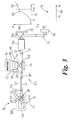
- Figure 1 is a schematic view of a prior art wavelength-stabilising fibre grating, having a laser diode joined to a fibre to which is spliced to another fibre having a pre-formed fibre grating; and
- Figures 2 and 3 are a schematic views showing how a wavelength-stabilising fibre grating is formed according to the invention, from a laser diode joined to a fibre in which a grating is subsequently formed.
-
- Figure 1 shows a prior art optical assembly 1, comprising a
semiconductor laser 2, here an infra-red laser diode, joined to a short length of single-mode optical fibre 4, typically about 1 m long. Thelaser diode 2 is mounted on asubstrate 6 within alaser diode module 8 that will normally contain other conventional components (not shown) such as a monitor photodiode, drive electronics, and a thermoelectric cooler. - Mounted on the
substrate 6 are a collimatinglens 10 positioned to collect and focusoptical radiation 12 from thelaser diode 2, and afibre mount 14 for receiving oneend 16 of the fibre 4. The fibre 4 is aligned and joined to the laser diode by thefibre mount 14, so that the focussed optical radiation is launched 18 into a single-mode core 20 of the fibre 4. - Once the fibre 4 has been successfully joined to the
laser diode 2, an initiallyfree end 22 of the fibre 4 is then joined at asplice 24 to a second short length ofoptical fibre 26, usually about 1 m to 2 m long. Thesecond fibre 26 has a similar single-mode core 28, that needs to be aligned to an accuracy of about 1 µm with respect to thefirst core 20 for good coupling efficiency, e.g. better than 90%, ofoptical radiation 30 into thesecond fibre 26. - The second fibre, referred to hereinafter as a "grating fibre" 26, has a pre-formed
optical grating 32, consisting of a plurality of alternatingbands 34 of high and low reflective index.Optical radiation 30 with a wavelength λ coupled into thegrating fibre 26 is then partially reflected 36 by thegrating 32. Most of the reflectedoptical radiation 36 is coupled via the first fibre 4 andcollimating lens 10 back into thelaser diode 2. Depending on the optical characteristics of thelaser diode 2 and the grating 32, an optimum amount for the reflectedoptical radiation 36 is between about 2% and 10%, and typically 5%. - An optical
fibre output connector 38 may be joined to afree end 40 of thegrating fibre 26, either before or after the grating fibre is spliced to the first fibre 4. Thecoupler 38 receives optical radiation transmitted 42 by thegrating 32. Most of this radiation is then available 44 from thecoupler 38 either for test purposes for measuring the optical characteristics of stabilised optical radiation 44 during manufacture, or for use as a stabilised source of optical radiation 44 in a finished product. - As described in the introduction, this arrangement suffers from a number of inconveniences, because the optical characteristics of the grating 32 may not be properly matched to the optical characteristics of the
laser diode 2 and interveningoptics 10. - A process for producing a wavelength-stabilising fibre grating coupled to a laser source according to the invention, is illustrated schematically in Figures 2 and 3. Components similar to those of Figure 1 are denoted by reference numerals incremented by 100.
- A conventional
laser diode module 108 having alaser source 102 and afibre mount 114, similar to that described above, is first aligned and joined to afree end 48 of a short length of single-modeoptical fibre 50, about 2 m to 3 m long. Optical radiation is launched 52 into acore 54 of the fibre towards anoutput connector 138 joined to afree end 55 of thefibre 50. Most of the launched optical radiation is then available 56 from theconnector 138 and may, for example, be coupled into an optical fibre (not shown) or directed by means of conventional optics such as abeam splitter 58 andmirror 60 towards optical test instrumentation such as anoptical power meter 62 orwave meter 64 to enable the optical characteristics of theoptical radiation 56 to be determined. - The
power meter 62 can be used to generate aplot 66 of optical power (P) 68 against the drive current (I) 70 used to energise thelaser diode 102. The drive current 70 is supplied to thelaser diode 102 via aninput line 72 connected to thelaser diode 102. The current I may be a d.c. current, but may carrytest signals 74 to enable thelaser module 108 to be tested over a range of operating conditions. The operating conditions over which thelaser module 108 is tested may include controlled temperature changes 76. - As shown in
plot 66, the P vs. I characteristic of anunstabilised laser diode 102 is normally linear above a threshold current It. Laser diode operation is usually constrained below a rated maximum current Imax in order to ensure an adequate laser lifetime. - Because the
fibre 50 initially has no grating, the wavelength λ of theoptical radiation 52 is unstabilised, as shown by thespectrum plot 78 of laser power (P) 68 against wavelength (λ) 80, generated using thewave meter 64. The laser wavelength can hop amongst a number ofmodes 80, which will tend to drift to a longer wavelength with increased laser power and temperature. - Once the
optical characteristics laser diode 102 have been determined, then a grating 132 can be formed in thefibre 50, as shown in Figure 3. Because the laser characteristics are known, it is possible to select in advance the grating properties such a strength and pitch that are likely to stabilise thelaser 102 in an optimum fashion. - The grating 132 can be formed using known techniques, such as a
NdYAG laser 84 andoptical imaging system 86 including amask 88 and focussingoptics 90, in order to irradiate the fibre with a sufficient intensity ofoptical radiation 92 to alter the refractive index of the fibre inbands 134 that extend transverse to thefibre core 54. The strength of the grating 132 can be controlled by the amount of exposure to the NdYAGoptical radiation 92, and thepitch 94 of the grating can be controlled by adjusting 96 the components of theoptical system 86. - Optionally, the
NdYAG laser 84 andoptical imaging system 86 can be moved longitudinally along the length of thefibre 50 to form the grating in a preferred location on thefibre 50. - During the formation of the grating 132, the optical radiation transmitted 95 by the grating and the output
optical radiation 144 start to become wavelength-stabilised as a proportion of the launchedoptical radiation 52 is reflected 97 by the grating. During this process, theoptical characteristics radiation 144 continue to be monitored by thepower meter 62 andwave meter 64. In particular, akink 98 in the P vs. I optical characteristic 66 can be observed above the maximum operating current Imax. As the strength of the grating increases, this kink may move down the P vs. I curve 66 towards Imax as the wavelength λ becomes stabilised at the grating wavelength λS. The formation of the grating can then cease once the wavelength λS is sufficiently stabilised across the full operating region includedtemperature changes 76, and before thekink 98 in the P vs. I optical characteristic 66 drops as far as the upper end of the operating current at Imax. - It is also possible to deduce from the stabilised output
optical radiation 144 optical characteristics of thegrating 132. For example, as thegrating 132 reflects moreoptical radiation 97 back towards thelaser source 102, the measured output optical power (P) 68 will tend to drop. - This process therefore allows each grating 132 to be formed and optimally matched to the
laser source 102 in a controlled manner that improves manufacturing yield and reduces cost. - The invention therefore provides a convenient and economical method and apparatus for forming a wavelength-stabilising fibre grating coupled to a laser source.
Claims (13)
- A method for producing a wavelength-stabilising fibre grating (132) coupled to a laser source (102), characterised in that the method comprises the steps of:i) aligning and joining an optical fibre (50) to the laser source (102), so that laser output optical radiation (112) is coupled (52) into the fibre (50);ii) determining one or more optical characteristics (66,78) of the laser source (102); andiii) after step i), forming in the optical fibre (50) a grating (132) for reflecting back (97) into the laser source (102) a proportion of said optical radiation (52) coupled into the optical fibre (50), in order to stabilise the output wavelength (80) of the laser source (102), and one or more optical characteristics (94,134) of said formed grating (132) are matched to the laser source (102) according to said one or more determined optical characteristics (66,78) of the laser source (102).
- A method as claimed in Claim 1, in which step ii) occurs at least in part between steps i) and iii).
- A method as claimed in Claim 1 or Claim 2, in which said determined optical characteristics (66,78) of the laser source (102) are used to choose desired optical characteristics (94,134) of the grating (132) prior to the formation of the grating (132) in the fibre (50).
- A method as claimed in any preceding claim, in which said one or more optical characteristics (66,78) of the laser source (102) are determined from optical radiation (144) emitted by a free end (55) of the optical fibre (50)
- A method as claimed in any preceding claim, in which step ii) occurs at least in part during step iii).
- A method as claimed in any preceding claim, in which said one or more optical characteristics (94,134) of the grating (132) being formed are determined from optical radiation emitted by a free end (55) of the optical fibre (50).
- A method as claimed in any preceding claim, in which the matched optical characteristics (94,134) of the grating (132) include any or all of: the strength (134) of the grating (132); the characteristic wavelength (λS) of the grating (132); and the location of the grating (132) on the fibre (50).
- A method as claimed in any preceding claims, in which the laser source (102) is electrically driven (72), and one of the determined optical characteristics (66,78) of the laser source (102) is the optical power vs. drive current characteristic (66) of the laser source (102).
- A method as claimed in any preceding claim, in which one of the determined optical characteristics (66,78) of the laser source (102) is the optical power vs. wavelength characteristic (78) of the laser source (102).
- A method as claimed in any preceding claim, in which one of the determined optical characteristics (66,78) of the laser source (102) is a temperature-dependent characteristic (76) in the absence of wavelength stabilisation by the grating (132).
- A method as claimed in any preceding claim, in which the wavelength (80) of the laser source (102) is stabilised to a single wavelength (λS) across a desired operating region of the laser source (102).
- A method as claimed in any preceding claim, in which the laser source is a semiconductor laser (102).
- An apparatus for making a wavelength-stabilising fibre grating (132) coupled to a laser source (102), characterised in that the apparatus comprises:i) means (114) for aligning and joining an optical fibre (50) to the laser source (102), so that laser output optical radiation (112) is coupled (52) into the fibre (50) ;ii) means (58,60,62,64) for determining one or more optical characteristics (66,78) of the laser source (102); andiii) means (84,86) for forming in the optical fibre a grating (132) for reflecting back (97) into the laser source (102) a proportion of said optical radiation coupled (52) into the optical fibre (50), in order to stabilise the output wavelength (λS) of the laser source (102), such that one or more optical characteristics (94,134) of said formed grating (132) are matched to the laser source (102) according to said one or more determined optical characteristics (66,78) of the laser source (102).
Priority Applications (1)
| Application Number | Priority Date | Filing Date | Title |
|---|---|---|---|
| EP01309724A EP1313186A1 (en) | 2001-11-19 | 2001-11-19 | Wavelength stabilised laser source comprising fibre grating |
Applications Claiming Priority (1)
| Application Number | Priority Date | Filing Date | Title |
|---|---|---|---|
| EP01309724A EP1313186A1 (en) | 2001-11-19 | 2001-11-19 | Wavelength stabilised laser source comprising fibre grating |
Publications (1)
| Publication Number | Publication Date |
|---|---|
| EP1313186A1 true EP1313186A1 (en) | 2003-05-21 |
Family
ID=8182471
Family Applications (1)
| Application Number | Title | Priority Date | Filing Date |
|---|---|---|---|
| EP01309724A Withdrawn EP1313186A1 (en) | 2001-11-19 | 2001-11-19 | Wavelength stabilised laser source comprising fibre grating |
Country Status (1)
| Country | Link |
|---|---|
| EP (1) | EP1313186A1 (en) |
Cited By (1)
| Publication number | Priority date | Publication date | Assignee | Title |
|---|---|---|---|---|
| CN111025462A (en) * | 2018-10-10 | 2020-04-17 | 贰陆特拉华公司 | Method of forming fiber bragg gratings in pre-assembled laser modules |
Citations (3)
| Publication number | Priority date | Publication date | Assignee | Title |
|---|---|---|---|---|
| US5719974A (en) * | 1993-01-29 | 1998-02-17 | British Telecommunications Public Limited Company | Method for customizing optical device configuration after packaging and packaged optical device for use therewith |
| US5870417A (en) * | 1996-12-20 | 1999-02-09 | Sdl, Inc. | Thermal compensators for waveguide DBR laser sources |
| EP1130717A2 (en) * | 1999-12-06 | 2001-09-05 | Fuji Photo Film Co., Ltd. | Semiconductor laser light source with external cavity |
-
2001
- 2001-11-19 EP EP01309724A patent/EP1313186A1/en not_active Withdrawn
Patent Citations (3)
| Publication number | Priority date | Publication date | Assignee | Title |
|---|---|---|---|---|
| US5719974A (en) * | 1993-01-29 | 1998-02-17 | British Telecommunications Public Limited Company | Method for customizing optical device configuration after packaging and packaged optical device for use therewith |
| US5870417A (en) * | 1996-12-20 | 1999-02-09 | Sdl, Inc. | Thermal compensators for waveguide DBR laser sources |
| EP1130717A2 (en) * | 1999-12-06 | 2001-09-05 | Fuji Photo Film Co., Ltd. | Semiconductor laser light source with external cavity |
Cited By (3)
| Publication number | Priority date | Publication date | Assignee | Title |
|---|---|---|---|---|
| CN111025462A (en) * | 2018-10-10 | 2020-04-17 | 贰陆特拉华公司 | Method of forming fiber bragg gratings in pre-assembled laser modules |
| CN111025462B (en) * | 2018-10-10 | 2021-08-17 | 贰陆特拉华公司 | Method of forming fiber bragg gratings in pre-assembled laser modules |
| JP7113799B2 (en) | 2018-10-10 | 2022-08-05 | ツー-シックス デラウェア インコーポレイテッド | How to Form a Fiber Bragg Grating in an Assembled Laser Module |
Similar Documents
| Publication | Publication Date | Title |
|---|---|---|
| US5717804A (en) | Integrated laser diode and fiber grating assembly | |
| JP4887549B2 (en) | Tunable laser | |
| EP0860917B1 (en) | Semiconductor laser module | |
| US7127139B2 (en) | Optical multiplexing method and optical multiplexer, and optical amplifier using same | |
| EP0459650A2 (en) | Semiconductor laser pump source | |
| US20020118715A1 (en) | Semiconductor laser module and Raman amplifier using the module | |
| JP2002500386A (en) | Integrated optical transceiver | |
| US20020048300A1 (en) | Semiconductor laser device for use in a laser module | |
| Seguin et al. | Diode-pumped Q-switched fiber laser | |
| US20040179797A1 (en) | Multi-wavelength optical fiber | |
| US6496619B2 (en) | Method for gain equalization, and device and system for use in carrying out the method | |
| US6618405B2 (en) | Semiconductor laser module and amplifier using the module | |
| US6246511B1 (en) | Apparatus and method to compensate for optical fiber amplifier gain variation | |
| US6499888B1 (en) | Wide ridge pump laser | |
| EP2110902B1 (en) | Apparatus for side fire fiber lasers | |
| EP1087477B1 (en) | Semiconductor laser module | |
| EP1284532A2 (en) | Semiconductor laser device and method for suppressing injection current | |
| US6400746B1 (en) | Pump laser with low grating reflectivity | |
| JP2000035554A (en) | Optical wavelength adjusting device, light source using the same, optical wavelength demultiplexer, and wavelength division multiplexing optical communication system | |
| US20030133482A1 (en) | Semiconductor laser device and method for reducing stimulated brillouin scattering (SBS) | |
| EP1203971A1 (en) | Depolarised semiconductor laser module, manufacturing method thereof and Raman amplifier | |
| Su et al. | Design of wavelength-switching erbium-doped fiber lasers with a multimode fiber Bragg grating using spatial-mode excitation and selection techniques | |
| WO2002016979A2 (en) | Fiberoptic bus, modulator, detector and emitter using cladding mode coupling | |
| Al-Mahrous et al. | A glue splicing method to join silica and fluoride fibers with low attenuation | |
| KR20150047699A (en) | Highly Efficeient External Cavity Tunable Laser |
Legal Events
| Date | Code | Title | Description |
|---|---|---|---|
| PUAI | Public reference made under article 153(3) epc to a published international application that has entered the european phase |
Free format text: ORIGINAL CODE: 0009012 |
|
| AK | Designated contracting states |
Designated state(s): AT BE CH CY DE DK ES FI FR GB GR IE IT LI LU MC NL PT SE TR |
|
| AX | Request for extension of the european patent |
Extension state: AL LT LV MK RO SI |
|
| AKX | Designation fees paid | ||
| 17P | Request for examination filed |
Effective date: 20030228 |
|
| REG | Reference to a national code |
Ref country code: DE Ref legal event code: 8566 |
|
| STAA | Information on the status of an ep patent application or granted ep patent |
Free format text: STATUS: THE APPLICATION IS DEEMED TO BE WITHDRAWN |
|
| 18D | Application deemed to be withdrawn |
Effective date: 20031122 |