EP1313174A2 - Female electrical terminal and electrical connector comprising the same - Google Patents
Female electrical terminal and electrical connector comprising the same Download PDFInfo
- Publication number
- EP1313174A2 EP1313174A2 EP02024518A EP02024518A EP1313174A2 EP 1313174 A2 EP1313174 A2 EP 1313174A2 EP 02024518 A EP02024518 A EP 02024518A EP 02024518 A EP02024518 A EP 02024518A EP 1313174 A2 EP1313174 A2 EP 1313174A2
- Authority
- EP
- European Patent Office
- Prior art keywords
- contact section
- tubular portion
- contact element
- electrical terminal
- terminal
- Prior art date
- Legal status (The legal status is an assumption and is not a legal conclusion. Google has not performed a legal analysis and makes no representation as to the accuracy of the status listed.)
- Granted
Links
Images

Classifications
-
- H—ELECTRICITY
- H01—ELECTRIC ELEMENTS
- H01R—ELECTRICALLY-CONDUCTIVE CONNECTIONS; STRUCTURAL ASSOCIATIONS OF A PLURALITY OF MUTUALLY-INSULATED ELECTRICAL CONNECTING ELEMENTS; COUPLING DEVICES; CURRENT COLLECTORS
- H01R13/00—Details of coupling devices of the kinds covered by groups H01R12/70 or H01R24/00 - H01R33/00
- H01R13/02—Contact members
- H01R13/15—Pins, blades or sockets having separate spring member for producing or increasing contact pressure
- H01R13/187—Pins, blades or sockets having separate spring member for producing or increasing contact pressure with spring member in the socket
-
- H—ELECTRICITY
- H01—ELECTRIC ELEMENTS
- H01R—ELECTRICALLY-CONDUCTIVE CONNECTIONS; STRUCTURAL ASSOCIATIONS OF A PLURALITY OF MUTUALLY-INSULATED ELECTRICAL CONNECTING ELEMENTS; COUPLING DEVICES; CURRENT COLLECTORS
- H01R13/00—Details of coupling devices of the kinds covered by groups H01R12/70 or H01R24/00 - H01R33/00
- H01R13/02—Contact members
- H01R13/10—Sockets for co-operation with pins or blades
- H01R13/11—Resilient sockets
- H01R13/113—Resilient sockets co-operating with pins or blades having a rectangular transverse section
Definitions
- the present invention relates to female electrical terminals and connectors comprising female electrical terminals.
- the female electrical terminals include protected contact elements for engaging complementary male terminals.
- a typical electrical connector combination includes a plug connector and a receptacle connector, both of which mount or house interengageable electrical terminals.
- the plug connector is inserted into or mated with the receptacle connector to interengage the terminals.
- the terminals may take a variety of configurations, including male and female or pin and socket terminals.
- Known female terminals comprise a generally tubular-shaped contact section for engaging a complementary male terminal, and a connection section on the opposing end for connection to a conducting wire.
- the contact section typically employs flexible elements for applying retentive normal forces to an engaged complementary male terminal.
- U.S. Pat. No. 6,095,874 discloses an electrical receptacle terminal comprising a contact section having a pair of opposed cantilever beam contact arms. Free ends of the contact arms are resiliently biased toward one another such that their original position defines a space that is of a smaller diameter than a complementary male terminal. The free ends flex outwardly upon insertion of a male terminal, thereby applying normal forces to the male terminal sufficient to maintain the inter-engagement and electrical connectivity.
- Female electrical terminal 9 includes a contact section 12 and a connection section 14.
- Contact section 12 is generally box -shaped or rectangular in cross-section and mounts a spring contact element 13 for resiliently gripping a male terminal. As can be seen in the figures, spring contact element 13 has an exposed leading edge 15.
- Quality control related to the manufacture of male and female electrical terminals, as well as related to methods of interengaging the same, may decrease the potential for misaligned engagement; however, the potential for tampering with the contact element, through the use of a small or sharp instrument, still exists when the spring contact element's leading edge is exposed.
- the contact element leading edge 18 is still exposed to potential failure-inducing damage.
- a female electrical terminal comprising a connection section for connection to a conducting wire and an opposing contact section for mating with a complementary male terminal.
- the contact section includes a bottom wall, two sidewalls extending upwardly from opposite sides of the bottom wall, and a front end.
- An entry portion is positioned adjacent the front end, and includes an entrance for guiding a complementary terminal into the contact section.
- a single flexible contact element is at least partially disposed within the contact section for urging a complementary male terminal into engagement with the bottom wall.
- the flexible contact element includes a leading edge positioned outside the periphery of the entrance such that access to the leading edge is prohibited.
- a female electrical terminal comprising a connection section for connection to a conducting wire and a contact section comprising a first tubular portion that forms an insertion pathway for a complementary male terminal, and a second tubular portion between the first tubular portion and the connection section.
- Central axes of the first and second tubular portions are misaligned such that a space is formed outside of the insertion pathway.
- a single flexible contact element is at least partially disposed within the contact section for urging an inserted complementary male terminal into engagement with an inner wall of the contact section.
- the contact element includes a leading edge that is positioned within the space formed outside of the insertion pathway.
- a female electrical terminal comprising a connection section for connection to a conducting wire and a contact section comprising a first tubular portion having an entrance for guiding a complementary male terminal into the contact section, and a second tubular portion between the first tubular portion and the connection section.
- An external opening is formed in the contact section and spaced apart from the firs tubular portion entrance.
- a single flexible contact element is at least partially disposed within the contact section for urging an inserted complementary male terminal into engagement with an inner wall of the contact section.
- the contact element includes a leading edge that extends through the external opening.
- an electrical connector comprising a housing including a passage extending through it, and an opening formed in a face of the housing for providing access to the passage.
- a female electrical terminal is at least partially disposed within the passage.
- the female electrical terminal comprises a connection section for connection to a conducting wire and a contact section comprising a first tubular portion having an entrance for guiding a complementary male terminal into the contact section which has been inserted into the housing opening, and a second tubular portion between the first tubular portion and the connection section.
- An external opening is formed in the contact section and spaced apart from the entrance.
- a single flexible contact element is at least partially disposed within the contact section for urging an inserted complementary male terminal into engagement with an inner wall of the contact section.
- the contact element includes a leading edge that extends through the external opening.
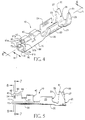
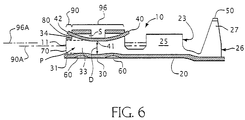
- female electrical terminal 10 includes a connection section 20 for connection to a conducting wire (an example of which is shown in Figures 9 and 10) and a contact section 30 for engaging a complementary male terminal (not shown).
- connection section 20 for connection to a conducting wire (an example of which is shown in Figures 9 and 10) and a contact section 30 for engaging a complementary male terminal (not shown).
- a conducting wire an example of which is shown in Figures 9 and 10.
- contact section 30 preferably comprises two tubular-shaped portions, first tubular portion 90 and second tubular portion 96, that are preferably arranged end to end.
- the tubular nature of contact section 30 is capable of taking many geometric forms, and being made by a varying number of walls or like structure. Accordingly, the illustrated and described embodiments are not limiting.
- First tubular portion 90 comprises first sidewalls 91a and 91b that have been converged to form a tubular enclosure, and an entry portion 11 having an entrance 70 for guiding a complementary male terminal into contact section 30.
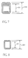
- First tubular portion 90 has an effective inner diameter ID and an effective outer diameter OD 1.
- Effective diameter means the diameter of a circle that either circumscribes the referenced element (effective outer diameter), or is inscribed by the referenced element (effective inner diameter).
- Second tubular portion 96 comprises second sidewalls 97a and 97b that, in a preferred embodiment, are longer than sidewalls 91a and 91b. Second tubular portion 96 has an effective inner diameter ID2 and an effective outer diameter OD2.
- a flexible contact element 40 is at least partially disposed within contact section 30 for urging a complementary male terminal into engagement with a contact section inner wall, such as bottom wall 31.
- contact element 40 is arcuate-shaped, having its apex 41 directed towards bottom wall 31.
- the distance D between apex 41 and bottom wall 31 is designed to be smaller in dimension than the diameter of the complementary male terminal.
- the required amount of applied forces may vary, and can be adjusted by altering any one or combination of the following variables: distance D; material properties of the complementary male terminal, such as surface roughness; and material properties of flexible contact element 40, such as thickness, surface characteristics, thermal treatment, material composition and the like.
- Protecting flexible contact element 40 from damage is an important aspect of the present invention. Minimally, damage to contact element 40 results in a non-reliable electrical connection between the inter-engaged terminals. In a worse case scenario, contact element 40 can be damaged and distorted to the extent that it becomes separated from contact section 30. Without the contact element 40, female terminal 10 will fail. Female terminals and electrical connectors comprising the same, as provided by the present invention, are useful in a variety of important electronic devices where loss of signal pass-through can be extremely detrimental.
- the present invention provides a robust and functional terminal design that at least decreases the potential for damage to contact element 40 and associated loss of signal
- first tubular portion 90 forms an insertion pathway P for a complementary male terminal that extends from entrance 70 and into the second tubular portion 96 of contact section 30.
- a space S exists outside the periphery of insertion pathway P, and correspondingly entrance 70.
- One way of creating space S is by misaligning central axes of the first and second tubular portions 90 and 96. That is, a central axis 90A of first tubular portion 90 is offset from a central axis 96A of second tubular portion 96.
- leading edge 42 is preferably extended through space S and positioned external to contact section 30. This can be accomplished by employing an external opening 80 within contact section 30, including, within either first tubular portion 90 or second tubular portion 96. Alternatively, and in a preferred embodiment, opening 80 is formed at the interface between the two tubular portions 90, 96. As can bee seen in the figures, front end 34 of second tubular portion 96 extends beyond the periphery of first tubular portion 90 (entry portion 11). This extension forms opening 80, which is capable of receiving contact element 40 and its leading edge 42.
- first and second tubular portions 90, 96 may be perfected through a number of techniques, including offsetting similarly sized and shaped portions.
- first and second tubular portions are sized differently, as is shown in the figures.
- effective inner and outer diameters ID1, OD1 of first tubular portion 90 are smaller than the effective inner diameter ID2 of second tubular portion 96.
- Projections extending from a contact section inner surface may be employed to improve electrical contact and retention of an engaged complementary male terminal. Retentive normal forces are concentrated at these projections.
- raised elements 60 are disposed on the inner surface of bottom wall 31.
- connection section 20 includes a wire barrel 23 for cradling an inserted conducting wire (such as that shown in Figure 10).
- Wire barrel 23 has wire crimp arms 24 and 25 that are capable of being crimped onto the conducting wire, thereby making an electrical connection between female terminal 10 and the conducting wire.
- Connection section 20 may also include an insulation barrel 26 for cradling insulation or other sheathing material that may be surrounding the conducting wire.
- Insulation barrel 26 is shown having insulation crimp arms 27 and 28 that are capable of being formed around wire sheathing.
- insulation crimp arms 27 and 28 have tapered ends 50 and 51 and a length that is greater than half of the width W of connection section 20.
- tapered ends 50 and 51 are preferably offset along a longitudinal axis L. This preferred arm length and offset arrangement provides for substantial overlap around a sheathed conducting wire, thereby ensuring a sufficient grip on the conducting wire to eliminate any potential for separation from the female terminal.
- connecting section 20 in the preferred embodiment is depicted as in-line with respect to contact section 30, it is equally possible for the entire connector to be a right-angle connector in which the connecting section 20 is transverse with respect to the contact section 30.
- Terminals of the present invention are preferably made from a base material comprising brass, which is plated with a material such as gold.
- the flexible contact element is preferably made from a base material including beryllium, copper, and alloys made from the same. Similar to the terminal body members, the flexible contact element may be plated with a suitable material, such as gold.
- the materials and terminal components of the present invention may optionally be processed or treated to impart improved functionality.
- pre-formed sections may be heat-treated to increase their ductility, which will make forming the sections into their final configuration much easier.
- Another example is knurling surfaces of the sectional elements, such that a better grip may be maintained on inserted terminals and conducting wires.
- Terminal components and the flexible contact elements of the present invention may be made by any of the methods known to persons having ordinary skill in the art.
- One known method includes stamping and forming from sheet material, wherein the formation of multiple sections and elements is done through progressive dies to impart the final terminal and contact element configurations.
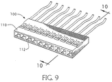
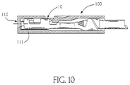
- receptacle 100 includes a housing 110 having a plurality of passages 111 and a plurality of openings 112 communicating with passages 111.
- a single female terminal 10 is disposed in each of passages 111.
- a complementary male connector (not shown) can be connected to receptacle 100 by inserting male terminals (not shown) through openings 112 and into female terminal contact sections 30.
- Receptacle 100 is preferably formed with thermoplastic materials using injection molding techniques. Suitable materials include polyphenylene sulfide, polymethylencecyclohexane terephthalate, liquid crystal polymer, polyphthalamide, nylon 4,6, polyesters and polyolefins. After housing 110 is molded, terminals 10 are inserted and secured in passageways 111. Alternatively, housing 110 may be molded around the terminals to form the electrical connector in a single step. The present invention, however, is not limited to such materials and manufacturing methods, but rather encompasses any material and related methods for forming the same, such as, for example, metallic castings, fabrications, and combinations thereof.
Landscapes
- Details Of Connecting Devices For Male And Female Coupling (AREA)
- Connector Housings Or Holding Contact Members (AREA)
Abstract
Description
Claims (20)
- A female electrical terminal (10) comprising:a contact section (30) for mating with a complementary male terminal, the contact section including a bottom wall (31), two sidewalls (97a, 97b) extending upwardly from opposite sides of the bottom wall (31), and a front end (34);an entry portion (11) adjacent the front end (34) including an entrance (70) for guiding a complementary terminal into the contact section (30); anda single flexible contact element (40) that is at least partially disposed within the contact section (30) for urging a complementary male terminal into engagement with the bottom wall (31), the flexible contact element (40) including a leading edge (42) positioned outside the periphery of the entrance (70) such that access to the leading edge (42) is prohibited.
- The electrical terminal (10) of claim 1, wherein one of the contact section (30) and the entry portion (11) comprises an external opening (80), and wherein the contact element leading edge (42) extends into the external opening (80).
- The electrical terminal (10) of claim 1, wherein a portion of the front end (34) extends beyond the periphery of the end portion (11) such than an external opening (80) is formed at the interface between the entry portion (11) and the front end (34), and wherein the contact element leading edge (42) extends into the external opening (80).
- The electrical terminal (10) of claim 3, wherein the external opening (80) is above the entry portion (11) and the contact element leading edge (42) extends through the external opening (80).
- The electrical terminal (10) of claim 1, wherein the contact element leading edge (42) is positioned between the front end (34) and the entrance (70).
- The electrical terminal (10) of claim 1, wherein said connection section is in-line with said contact section.
- A female electrical terminal (10) comprising:a contact section (30) for mating with a complementary male terminal, the contact section including a bottom wall (31), two sidewalls (97a, 97b) extending upwardly from opposite sides of the bottom wall (31), and a front end (34);an entry portion (11) adjacent the front end (34), wherein some of the front end (34) extends beyond the periphery of the entry portion (11) such that an external opening (80) is formed at the interface between the entry portion (11) and the front end (34); anda single flexible contact element (40) that is at least partially disposed within the contact section (30) for urging a complementary male terminal into engagement with the bottom wall (31), the flexible contact element (40) including a leading edge (42) extending into the external opening (80).
- The electrical terminal (10) of claim 4 or 7, wherein the entry portion (11) has an effective outer diameter (OD1) that is smaller than an effective inner diameter (ID2) of the front end.
- The electrical terminal (10) of claim 7, wherein the contact section (30) and entry portion (11) are made from a single sheet of material, the entry portion (11) being formed by bending and converging first sidewalls (91a, 91b), and the contact section being formed by bending and converging second sidewalls (97a, 97b) that are longer than the first sidewalls (91a, 91b).
- A female electrical terminal (10) comprising:a contact section (30) comprising a first tubular portion (90) that forms an insertion pathway (P) for a complementary male terminal, and a second tubular portion (96) between the first tubular portion (90) and the connection section (20) wherein central axes (90A, 96A) of the first and second tubular portions (90, 96) are misaligned such that a space (S) is formed outside of the insertion pathway (P);a single flexible contact element (40) at least partially disposed within the contact section (30) for urging an inserted complementary male terminal into engagement with an inner wall (31) of the contact section (30), the contact element (40) including a leading edge (42) that is positioned within the space (S).
- The electrical terminal (10) of claim 10, further comprising an external opening (80) in the contact section (30) spaced apart from an entrance (70) to the first tubular portion (90), and wherein the contact element leading edge (42) extends through the external opening (80).
- The electrical terminal (10) of claim 11, wherein the contact element leading edge (42) is positioned externally and above the first tubular portion (90).
- The electrical terminal (10) of claim 10, wherein the first tubular portion (90) has a smaller effective inner diameter (ID1) than that of the second tubular portion (96).
- The electrical terminal (10) of claim 10, wherein the contact section (30) is made from a single sheet of material, the first tubular portion (90) being formed by bending and converging first sidewalls (91a, 91), the second tubular portion (96) being formed by bending and converging second sidewalls (97a, 97b) that are longer than the first sidewalls (91a, 91b).
- A female electrical terminal (10) comprising:a contact section (30) comprising a first tubular portion (90) having an entrance (70) for guiding a complementary male terminal into the contact section (30), and a second tubular portion (96) between the first tubular portion (90) and the connection section (20);an external opening (80) formed in the contact section (30) and spaced apart from the entrance (70); anda single flexible contact element (40) at least partially disposed within the contact section (30) for urging an inserted complementary male terminal into engagement with an inner wall (31) of the contact section (30), the contact element (40) including a leading edge (42) that extends through the external opening (80).
- The electrical terminal (10) of claim 15, wherein the contact element leading edge (42) is positioned above the first tubular portion (90).
- The electrical terminal (10) of claim 10 or 15, wherein engagement of the contact element (40) by a complementary male terminal is limited to areas within the second tubular portion (96).
- The electrical terminal (10) of claim 1 or 15, further comprising a connection section (20) for connection to a conducting wire.
- An electrical connector (100) comprising:a housing (110) including a passage (111) extending therethrough, and an opening (112) formed in a face of the housing (110) for providing access to the passage (111); and a female electrical terminal (10) according to claim 15 at least partially disposed within the passage (111).
- The connector (100) of claim 19, wherein some of the second tubular portion (96) extends beyond the periphery of the first tubular portion (90) to form the external opening (80).
Applications Claiming Priority (2)
| Application Number | Priority Date | Filing Date | Title |
|---|---|---|---|
| US989271 | 1992-12-11 | ||
| US09/989,271 US7241190B2 (en) | 2001-11-20 | 2001-11-20 | Female electrical terminal and electrical connector comprising the same |
Publications (3)
| Publication Number | Publication Date |
|---|---|
| EP1313174A2 true EP1313174A2 (en) | 2003-05-21 |
| EP1313174A3 EP1313174A3 (en) | 2004-02-04 |
| EP1313174B1 EP1313174B1 (en) | 2006-03-08 |
Family
ID=25534938
Family Applications (1)
| Application Number | Title | Priority Date | Filing Date |
|---|---|---|---|
| EP02024518A Expired - Lifetime EP1313174B1 (en) | 2001-11-20 | 2002-10-31 | Female electrical terminal and electrical connector comprising the same |
Country Status (6)
| Country | Link |
|---|---|
| US (1) | US7241190B2 (en) |
| EP (1) | EP1313174B1 (en) |
| JP (1) | JP4316223B2 (en) |
| CN (1) | CN100416933C (en) |
| DE (1) | DE60209611T2 (en) |
| TW (1) | TW558157U (en) |
Cited By (2)
| Publication number | Priority date | Publication date | Assignee | Title |
|---|---|---|---|---|
| EP1544952A1 (en) * | 2003-12-19 | 2005-06-22 | J.S.T. Mfg. Co., Ltd. | Female contact |
| FR3017251A1 (en) * | 2014-02-06 | 2015-08-07 | Dai Ichi Seiko Co Ltd | TERMINAL OF CONNECTOR |
Families Citing this family (23)
| Publication number | Priority date | Publication date | Assignee | Title |
|---|---|---|---|---|
| US7241190B2 (en) * | 2001-11-20 | 2007-07-10 | Fci Americas Technology, Inc. | Female electrical terminal and electrical connector comprising the same |
| US7537497B2 (en) * | 2005-09-26 | 2009-05-26 | Fci Americas Technology, Inc. | Multi-piece electrical receptacle terminal |
| SE529718C2 (en) | 2006-03-09 | 2007-11-06 | Plastab I Anderstorp Ab | Contact finger with grooves |
| SE529717C2 (en) * | 2006-03-09 | 2007-11-06 | Plastab I Anderstorp Ab | Contact finger with transverse recess, adjustable in recess on corresponding contact finger |
| DE102007040937B3 (en) * | 2007-08-30 | 2009-01-15 | Tyco Electronics Amp Gmbh | Electric contact |
| GB0815833D0 (en) * | 2008-08-29 | 2008-10-08 | Cinch Connections Ltd | Electrical conenctors |
| JP2014049375A (en) * | 2012-09-03 | 2014-03-17 | Yazaki Corp | Connection terminal |
| JP6044513B2 (en) * | 2013-03-21 | 2016-12-14 | 住友電装株式会社 | Terminal fitting |
| EP2866306B1 (en) * | 2013-10-23 | 2020-07-29 | Aptiv Technologies Limited | Contact socket for an electric plug |
| JP2015159094A (en) * | 2014-02-25 | 2015-09-03 | 矢崎総業株式会社 | connection terminal |
| JP6183665B2 (en) * | 2015-08-05 | 2017-08-23 | 住友電装株式会社 | Terminal |
| US10824379B2 (en) | 2016-03-07 | 2020-11-03 | Hewlett-Packard Development Company, L.P. | Auxiliary device identification |
| US9601866B1 (en) * | 2016-07-11 | 2017-03-21 | Elemental LED, Inc. | Strain relief and joint support |
| DE202017101148U1 (en) * | 2017-03-01 | 2018-06-04 | Wago Verwaltungsgesellschaft Mbh | Wire connecting terminal element |
| US20200083632A1 (en) * | 2017-05-09 | 2020-03-12 | Iriso Electronics Co., Ltd. | Connector |
| CN111262077B (en) | 2017-06-23 | 2022-01-14 | 上海莫仕连接器有限公司 | Power supply connector |
| TWD192839S (en) * | 2018-01-29 | 2018-09-11 | 唐虞企業股份有限公司 | Connector terminal |
| CN110247232B (en) * | 2018-03-09 | 2024-08-27 | 泰科电子(上海)有限公司 | Conductive terminals and connectors |
| JP6999610B2 (en) * | 2019-07-19 | 2022-01-18 | 矢崎総業株式会社 | connector |
| DE102019211762A1 (en) * | 2019-08-06 | 2021-02-11 | Lear Corporation | ELECTRIC CLEAN-BODY CONNECTION |
| CN111430966B (en) * | 2020-03-20 | 2021-07-20 | 番禺得意精密电子工业有限公司 | Electric connector and connecting terminal |
| DE102020108278B4 (en) * | 2020-03-25 | 2023-12-28 | Lear Corporation | Electrical connector and connection plug system |
| USD1108376S1 (en) * | 2023-12-14 | 2026-01-06 | J.S.T. Corporation | Electrical female terminal |
Family Cites Families (29)
| Publication number | Priority date | Publication date | Assignee | Title |
|---|---|---|---|---|
| US4342498A (en) * | 1979-03-26 | 1982-08-03 | Akzona Incorporated | Electrical socket |
| JPH0162671U (en) * | 1987-10-13 | 1989-04-21 | ||
| US5271741A (en) | 1990-02-21 | 1993-12-21 | Yazaki Corporation | Female socket contact |
| JPH0633659Y2 (en) * | 1990-02-21 | 1994-08-31 | 矢崎総業株式会社 | Female terminal fitting |
| JPH0494275U (en) | 1991-01-11 | 1992-08-17 | ||
| FR2701170B1 (en) | 1993-02-02 | 1995-03-17 | Framatome Connectors France | Female electrical contact with flexible blade. |
| JP3119418B2 (en) * | 1994-04-20 | 2000-12-18 | 矢崎総業株式会社 | Terminal for waterproof connector |
| US5476399A (en) | 1994-05-20 | 1995-12-19 | At&T Global Information Solutions Company | High frequency/low temperature electronic socket pin |
| JP3093954B2 (en) * | 1995-05-26 | 2000-10-03 | 矢崎総業株式会社 | Female terminal fitting |
| US5781143A (en) * | 1996-02-06 | 1998-07-14 | Rossin; John A. | Auto-acquire of transmitter ID by receiver |
| GB9612922D0 (en) | 1996-06-20 | 1996-08-21 | Amp Gmbh | Electrical terminal |
| US5885159A (en) * | 1996-08-13 | 1999-03-23 | Rokenbok Toy Company | System for, and method of, controlling the operation of toys |
| JP3748635B2 (en) * | 1996-09-20 | 2006-02-22 | アルプス電気株式会社 | Communication device |
| US5730628A (en) | 1996-09-25 | 1998-03-24 | Pacesetter, Inc. | Multi-contact connector for an implantable medical device |
| JPH10134872A (en) | 1996-10-16 | 1998-05-22 | Whitaker Corp:The | Electrical contacts |
| JP3724610B2 (en) | 1996-10-21 | 2005-12-07 | 住友電装株式会社 | Terminal bracket cover |
| JP3728639B2 (en) | 1997-05-09 | 2005-12-21 | 日本モレックス株式会社 | Female electrical terminal |
| US6196884B1 (en) | 1997-07-22 | 2001-03-06 | Harness System Technologies Research, Ltd. | Female metal terminal that stably connects with male metal terminal |
| DE69932471T2 (en) | 1998-05-18 | 2007-08-23 | The Whitaker Corp., Wilmington | One-piece electrical connection socket |
| US6175784B1 (en) * | 1999-08-09 | 2001-01-16 | Honeywell, Inc. | Remotely operated rail car status monitor and control system |
| JP3544155B2 (en) | 1999-10-22 | 2004-07-21 | 住友電装株式会社 | Terminal fitting |
| JP2001135367A (en) | 1999-11-08 | 2001-05-18 | Yazaki Corp | ID terminal |
| JP2001143774A (en) | 1999-11-12 | 2001-05-25 | Yazaki Corp | Pressure contact terminal |
| ATE243375T1 (en) | 1999-11-30 | 2003-07-15 | Preci Dip Durtal Sa | CONTACT ORGANIZER FOR AN ELECTRICAL CONNECTOR |
| JP2001229988A (en) | 2000-02-21 | 2001-08-24 | Yazaki Corp | ID terminal |
| DE50100410D1 (en) | 2000-10-12 | 2003-08-28 | Tyco Electronics Amp Gmbh | Contact socket for an electrical connector |
| JP3495020B2 (en) | 2000-11-24 | 2004-02-09 | 矢崎総業株式会社 | connector |
| JP3527900B2 (en) * | 2001-07-17 | 2004-05-17 | コナミ株式会社 | Remote control system, transmitter and driving device thereof |
| US7241190B2 (en) * | 2001-11-20 | 2007-07-10 | Fci Americas Technology, Inc. | Female electrical terminal and electrical connector comprising the same |
-
2001
- 2001-11-20 US US09/989,271 patent/US7241190B2/en not_active Expired - Lifetime
-
2002
- 2002-10-18 TW TW091216682U patent/TW558157U/en not_active IP Right Cessation
- 2002-10-31 DE DE60209611T patent/DE60209611T2/en not_active Expired - Lifetime
- 2002-10-31 EP EP02024518A patent/EP1313174B1/en not_active Expired - Lifetime
- 2002-11-15 CN CNB021495963A patent/CN100416933C/en not_active Expired - Fee Related
- 2002-11-20 JP JP2002336906A patent/JP4316223B2/en not_active Expired - Fee Related
Cited By (3)
| Publication number | Priority date | Publication date | Assignee | Title |
|---|---|---|---|---|
| EP1544952A1 (en) * | 2003-12-19 | 2005-06-22 | J.S.T. Mfg. Co., Ltd. | Female contact |
| US7229328B2 (en) | 2003-12-19 | 2007-06-12 | J.S.T. Mfg. Co. Ltd. | Female contact |
| FR3017251A1 (en) * | 2014-02-06 | 2015-08-07 | Dai Ichi Seiko Co Ltd | TERMINAL OF CONNECTOR |
Also Published As
| Publication number | Publication date |
|---|---|
| EP1313174B1 (en) | 2006-03-08 |
| US7241190B2 (en) | 2007-07-10 |
| TW558157U (en) | 2003-10-11 |
| US20030096540A1 (en) | 2003-05-22 |
| CN100416933C (en) | 2008-09-03 |
| JP4316223B2 (en) | 2009-08-19 |
| CN1420587A (en) | 2003-05-28 |
| EP1313174A3 (en) | 2004-02-04 |
| DE60209611T2 (en) | 2006-12-14 |
| JP2003187893A (en) | 2003-07-04 |
| DE60209611D1 (en) | 2006-05-04 |
Similar Documents
| Publication | Publication Date | Title |
|---|---|---|
| EP1313174B1 (en) | Female electrical terminal and electrical connector comprising the same | |
| EP2500982B1 (en) | Wire-to-wire connector | |
| US6033270A (en) | Electrical connector device | |
| EP2178177B1 (en) | Shield connector | |
| KR0141897B1 (en) | Insulator displacement electrical connector with strain relief | |
| US5683269A (en) | Shielded electrical connector with cable strain relief | |
| US4416504A (en) | Contact with dual cantilevered arms with narrowed, complimentary tip portions | |
| US7717759B2 (en) | Female terminal with guiding piece | |
| US5980336A (en) | Electrical terminal | |
| CN102157826B (en) | Connector apparatus | |
| US5957734A (en) | Tuning fork inline connection system | |
| US20150214670A1 (en) | Electrical connector having improved anti-emi performance | |
| AU611057B2 (en) | Electrical connector | |
| US7485016B2 (en) | Female terminal with guiding piece | |
| JPH0371741B2 (en) | ||
| EP0952631B1 (en) | Male contact | |
| CN111247697A (en) | Flat electric connector | |
| CN1110012A (en) | Electrical connector with slotted beam contact | |
| JP2024529550A (en) | Connector Contacts | |
| EP0704110A1 (en) | Insulated terminal with integral dual flared barrel | |
| US11641068B2 (en) | Electrical crimp terminal for electrical wire | |
| US20050009411A1 (en) | Electrical contact for cable assembly | |
| WO2000059073A1 (en) | Female electrical terminal with arc arresting portion | |
| US4108525A (en) | Hermaphroditic edgeboard connectors | |
| JP3611109B2 (en) | Assembly method of shield terminal |
Legal Events
| Date | Code | Title | Description |
|---|---|---|---|
| PUAI | Public reference made under article 153(3) epc to a published international application that has entered the european phase |
Free format text: ORIGINAL CODE: 0009012 |
|
| AK | Designated contracting states |
Designated state(s): AT BE BG CH CY CZ DE DK EE ES FI FR GB GR IE IT LI LU MC NL PT SE SK TR |
|
| AX | Request for extension of the european patent |
Extension state: AL LT LV MK RO SI |
|
| PUAL | Search report despatched |
Free format text: ORIGINAL CODE: 0009013 |
|
| AK | Designated contracting states |
Kind code of ref document: A3 Designated state(s): AT BE BG CH CY CZ DE DK EE ES FI FR GB GR IE IT LI LU MC NL PT SE SK TR |
|
| AX | Request for extension of the european patent |
Extension state: AL LT LV MK RO SI |
|
| RIC1 | Information provided on ipc code assigned before grant |
Ipc: 7H 01R 13/11 A Ipc: 7H 01R 13/187 B |
|
| 17P | Request for examination filed |
Effective date: 20040527 |
|
| 17Q | First examination report despatched |
Effective date: 20040812 |
|
| AKX | Designation fees paid |
Designated state(s): DE FR GB |
|
| GRAP | Despatch of communication of intention to grant a patent |
Free format text: ORIGINAL CODE: EPIDOSNIGR1 |
|
| GRAP | Despatch of communication of intention to grant a patent |
Free format text: ORIGINAL CODE: EPIDOSNIGR1 |
|
| GRAS | Grant fee paid |
Free format text: ORIGINAL CODE: EPIDOSNIGR3 |
|
| RAP1 | Party data changed (applicant data changed or rights of an application transferred) |
Owner name: FCI |
|
| GRAA | (expected) grant |
Free format text: ORIGINAL CODE: 0009210 |
|
| AK | Designated contracting states |
Kind code of ref document: B1 Designated state(s): DE FR GB |
|
| REG | Reference to a national code |
Ref country code: GB Ref legal event code: FG4D |
|
| REF | Corresponds to: |
Ref document number: 60209611 Country of ref document: DE Date of ref document: 20060504 Kind code of ref document: P |
|
| ET | Fr: translation filed | ||
| PLBE | No opposition filed within time limit |
Free format text: ORIGINAL CODE: 0009261 |
|
| STAA | Information on the status of an ep patent application or granted ep patent |
Free format text: STATUS: NO OPPOSITION FILED WITHIN TIME LIMIT |
|
| 26N | No opposition filed |
Effective date: 20061211 |
|
| PGFP | Annual fee paid to national office [announced via postgrant information from national office to epo] |
Ref country code: GB Payment date: 20070918 Year of fee payment: 6 |
|
| GBPC | Gb: european patent ceased through non-payment of renewal fee |
Effective date: 20081031 |
|
| PG25 | Lapsed in a contracting state [announced via postgrant information from national office to epo] |
Ref country code: GB Free format text: LAPSE BECAUSE OF NON-PAYMENT OF DUE FEES Effective date: 20081031 |
|
| REG | Reference to a national code |
Ref country code: FR Ref legal event code: CA |
|
| REG | Reference to a national code |
Ref country code: DE Ref legal event code: R082 Ref document number: 60209611 Country of ref document: DE Representative=s name: BEETZ & PARTNER MBB PATENTANWAELTE, DE Effective date: 20120419 Ref country code: DE Ref legal event code: R082 Ref document number: 60209611 Country of ref document: DE Representative=s name: BEETZ & PARTNER MBB PATENT- UND RECHTSANWAELTE, DE Effective date: 20120419 Ref country code: DE Ref legal event code: R081 Ref document number: 60209611 Country of ref document: DE Owner name: FCI, FR Free format text: FORMER OWNER: FCI, VERSAILLES, FR Effective date: 20120419 Ref country code: DE Ref legal event code: R082 Ref document number: 60209611 Country of ref document: DE Representative=s name: BEETZ & PARTNER PATENT- UND RECHTSANWAELTE, DE Effective date: 20120419 |
|
| REG | Reference to a national code |
Ref country code: FR Ref legal event code: PLFP Year of fee payment: 14 |
|
| PGFP | Annual fee paid to national office [announced via postgrant information from national office to epo] |
Ref country code: FR Payment date: 20150924 Year of fee payment: 14 |
|
| PGFP | Annual fee paid to national office [announced via postgrant information from national office to epo] |
Ref country code: DE Payment date: 20151030 Year of fee payment: 14 |
|
| REG | Reference to a national code |
Ref country code: DE Ref legal event code: R119 Ref document number: 60209611 Country of ref document: DE |
|
| REG | Reference to a national code |
Ref country code: FR Ref legal event code: ST Effective date: 20170630 |
|
| PG25 | Lapsed in a contracting state [announced via postgrant information from national office to epo] |
Ref country code: FR Free format text: LAPSE BECAUSE OF NON-PAYMENT OF DUE FEES Effective date: 20161102 Ref country code: DE Free format text: LAPSE BECAUSE OF NON-PAYMENT OF DUE FEES Effective date: 20170503 |