EP1312972A1 - Liquid crystal display device - Google Patents
Liquid crystal display device Download PDFInfo
- Publication number
- EP1312972A1 EP1312972A1 EP01947923A EP01947923A EP1312972A1 EP 1312972 A1 EP1312972 A1 EP 1312972A1 EP 01947923 A EP01947923 A EP 01947923A EP 01947923 A EP01947923 A EP 01947923A EP 1312972 A1 EP1312972 A1 EP 1312972A1
- Authority
- EP
- European Patent Office
- Prior art keywords
- liquid crystal
- layer
- display device
- crystal display
- reflective
- Prior art date
- Legal status (The legal status is an assumption and is not a legal conclusion. Google has not performed a legal analysis and makes no representation as to the accuracy of the status listed.)
- Withdrawn
Links
- 239000004973 liquid crystal related substance Substances 0.000 title claims abstract description 188
- 239000011521 glass Substances 0.000 claims abstract description 25
- 229920000642 polymer Polymers 0.000 claims abstract description 16
- 238000010276 construction Methods 0.000 claims description 43
- 239000000758 substrate Substances 0.000 claims description 31
- 239000004986 Cholesteric liquid crystals (ChLC) Substances 0.000 claims description 20
- 239000010409 thin film Substances 0.000 claims description 16
- 230000001678 irradiating effect Effects 0.000 claims description 3
- 239000011159 matrix material Substances 0.000 claims description 3
- 239000010408 film Substances 0.000 claims description 2
- 239000005276 holographic polymer dispersed liquid crystals (HPDLCs) Substances 0.000 abstract description 36
- 230000008859 change Effects 0.000 abstract description 2
- 239000007788 liquid Substances 0.000 abstract description 2
- 238000002310 reflectometry Methods 0.000 abstract 3
- 238000002834 transmittance Methods 0.000 description 14
- 238000000034 method Methods 0.000 description 7
- 238000000016 photochemical curing Methods 0.000 description 6
- 239000005264 High molar mass liquid crystal Substances 0.000 description 5
- 239000000126 substance Substances 0.000 description 5
- 239000004988 Nematic liquid crystal Substances 0.000 description 4
- 239000003086 colorant Substances 0.000 description 4
- 239000002131 composite material Substances 0.000 description 4
- 239000011295 pitch Substances 0.000 description 4
- 230000008901 benefit Effects 0.000 description 3
- 230000008569 process Effects 0.000 description 3
- 230000009471 action Effects 0.000 description 2
- 230000015572 biosynthetic process Effects 0.000 description 2
- QVGXLLKOCUKJST-UHFFFAOYSA-N atomic oxygen Chemical compound [O] QVGXLLKOCUKJST-UHFFFAOYSA-N 0.000 description 1
- 230000005540 biological transmission Effects 0.000 description 1
- 238000006243 chemical reaction Methods 0.000 description 1
- 230000000295 complement effect Effects 0.000 description 1
- 230000000694 effects Effects 0.000 description 1
- 238000005530 etching Methods 0.000 description 1
- 239000000499 gel Substances 0.000 description 1
- 238000000227 grinding Methods 0.000 description 1
- 230000006872 improvement Effects 0.000 description 1
- 238000004519 manufacturing process Methods 0.000 description 1
- 238000002156 mixing Methods 0.000 description 1
- 239000012299 nitrogen atmosphere Substances 0.000 description 1
- 239000001301 oxygen Substances 0.000 description 1
- 229910052760 oxygen Inorganic materials 0.000 description 1
- 229920006254 polymer film Polymers 0.000 description 1
- 125000006850 spacer group Chemical group 0.000 description 1
Images





Classifications
-
- G—PHYSICS
- G02—OPTICS
- G02F—OPTICAL DEVICES OR ARRANGEMENTS FOR THE CONTROL OF LIGHT BY MODIFICATION OF THE OPTICAL PROPERTIES OF THE MEDIA OF THE ELEMENTS INVOLVED THEREIN; NON-LINEAR OPTICS; FREQUENCY-CHANGING OF LIGHT; OPTICAL LOGIC ELEMENTS; OPTICAL ANALOGUE/DIGITAL CONVERTERS
- G02F1/00—Devices or arrangements for the control of the intensity, colour, phase, polarisation or direction of light arriving from an independent light source, e.g. switching, gating or modulating; Non-linear optics
- G02F1/01—Devices or arrangements for the control of the intensity, colour, phase, polarisation or direction of light arriving from an independent light source, e.g. switching, gating or modulating; Non-linear optics for the control of the intensity, phase, polarisation or colour
- G02F1/13—Devices or arrangements for the control of the intensity, colour, phase, polarisation or direction of light arriving from an independent light source, e.g. switching, gating or modulating; Non-linear optics for the control of the intensity, phase, polarisation or colour based on liquid crystals, e.g. single liquid crystal display cells
- G02F1/133—Constructional arrangements; Operation of liquid crystal cells; Circuit arrangements
- G02F1/1333—Constructional arrangements; Manufacturing methods
- G02F1/1334—Constructional arrangements; Manufacturing methods based on polymer dispersed liquid crystals, e.g. microencapsulated liquid crystals
-
- G—PHYSICS
- G02—OPTICS
- G02F—OPTICAL DEVICES OR ARRANGEMENTS FOR THE CONTROL OF LIGHT BY MODIFICATION OF THE OPTICAL PROPERTIES OF THE MEDIA OF THE ELEMENTS INVOLVED THEREIN; NON-LINEAR OPTICS; FREQUENCY-CHANGING OF LIGHT; OPTICAL LOGIC ELEMENTS; OPTICAL ANALOGUE/DIGITAL CONVERTERS
- G02F1/00—Devices or arrangements for the control of the intensity, colour, phase, polarisation or direction of light arriving from an independent light source, e.g. switching, gating or modulating; Non-linear optics
- G02F1/01—Devices or arrangements for the control of the intensity, colour, phase, polarisation or direction of light arriving from an independent light source, e.g. switching, gating or modulating; Non-linear optics for the control of the intensity, phase, polarisation or colour
- G02F1/13—Devices or arrangements for the control of the intensity, colour, phase, polarisation or direction of light arriving from an independent light source, e.g. switching, gating or modulating; Non-linear optics for the control of the intensity, phase, polarisation or colour based on liquid crystals, e.g. single liquid crystal display cells
- G02F1/133—Constructional arrangements; Operation of liquid crystal cells; Circuit arrangements
- G02F1/1333—Constructional arrangements; Manufacturing methods
- G02F1/1335—Structural association of cells with optical devices, e.g. polarisers or reflectors
- G02F1/133553—Reflecting elements
-
- G—PHYSICS
- G02—OPTICS
- G02F—OPTICAL DEVICES OR ARRANGEMENTS FOR THE CONTROL OF LIGHT BY MODIFICATION OF THE OPTICAL PROPERTIES OF THE MEDIA OF THE ELEMENTS INVOLVED THEREIN; NON-LINEAR OPTICS; FREQUENCY-CHANGING OF LIGHT; OPTICAL LOGIC ELEMENTS; OPTICAL ANALOGUE/DIGITAL CONVERTERS
- G02F1/00—Devices or arrangements for the control of the intensity, colour, phase, polarisation or direction of light arriving from an independent light source, e.g. switching, gating or modulating; Non-linear optics
- G02F1/01—Devices or arrangements for the control of the intensity, colour, phase, polarisation or direction of light arriving from an independent light source, e.g. switching, gating or modulating; Non-linear optics for the control of the intensity, phase, polarisation or colour
- G02F1/13—Devices or arrangements for the control of the intensity, colour, phase, polarisation or direction of light arriving from an independent light source, e.g. switching, gating or modulating; Non-linear optics for the control of the intensity, phase, polarisation or colour based on liquid crystals, e.g. single liquid crystal display cells
- G02F1/133—Constructional arrangements; Operation of liquid crystal cells; Circuit arrangements
- G02F1/1333—Constructional arrangements; Manufacturing methods
- G02F1/1347—Arrangement of liquid crystal layers or cells in which the final condition of one light beam is achieved by the addition of the effects of two or more layers or cells
- G02F1/13471—Arrangement of liquid crystal layers or cells in which the final condition of one light beam is achieved by the addition of the effects of two or more layers or cells in which all the liquid crystal cells or layers remain transparent, e.g. FLC, ECB, DAP, HAN, TN, STN, SBE-LC cells
- G02F1/13473—Arrangement of liquid crystal layers or cells in which the final condition of one light beam is achieved by the addition of the effects of two or more layers or cells in which all the liquid crystal cells or layers remain transparent, e.g. FLC, ECB, DAP, HAN, TN, STN, SBE-LC cells for wavelength filtering or for colour display without the use of colour mosaic filters
-
- G—PHYSICS
- G02—OPTICS
- G02F—OPTICAL DEVICES OR ARRANGEMENTS FOR THE CONTROL OF LIGHT BY MODIFICATION OF THE OPTICAL PROPERTIES OF THE MEDIA OF THE ELEMENTS INVOLVED THEREIN; NON-LINEAR OPTICS; FREQUENCY-CHANGING OF LIGHT; OPTICAL LOGIC ELEMENTS; OPTICAL ANALOGUE/DIGITAL CONVERTERS
- G02F1/00—Devices or arrangements for the control of the intensity, colour, phase, polarisation or direction of light arriving from an independent light source, e.g. switching, gating or modulating; Non-linear optics
- G02F1/01—Devices or arrangements for the control of the intensity, colour, phase, polarisation or direction of light arriving from an independent light source, e.g. switching, gating or modulating; Non-linear optics for the control of the intensity, phase, polarisation or colour
- G02F1/13—Devices or arrangements for the control of the intensity, colour, phase, polarisation or direction of light arriving from an independent light source, e.g. switching, gating or modulating; Non-linear optics for the control of the intensity, phase, polarisation or colour based on liquid crystals, e.g. single liquid crystal display cells
- G02F1/133—Constructional arrangements; Operation of liquid crystal cells; Circuit arrangements
- G02F1/1333—Constructional arrangements; Manufacturing methods
- G02F1/1334—Constructional arrangements; Manufacturing methods based on polymer dispersed liquid crystals, e.g. microencapsulated liquid crystals
- G02F1/13342—Holographic polymer dispersed liquid crystals
Definitions
- the present invention relates to a liquid crystal display device for displaying information.
- Reflective liquid crystal displays have come into widespread use in portable applications due to their low power consumption.
- reflective liquid crystal display devices capable of full-color display are now under development.
- a reflective liquid crystal display device uses ambient light as a light source and can provide display with high picture quality when used outside in sunlight, in contrast, the display of a transmissive liquid crystal display device generally suffers from low contrast and poor visibility when used outside in sunlight.
- the visibility of a reflective liquid crystal display device is poor when used outside at night or in a room with poor lighting and cannot obtain the image quality that is possible in a transmissive liquid crystal display device.
- a liquid crystal display device is therefore desired that is capable of reflective display in a bright setting and that can display using a supplementary light source in a dark setting.
- a semi-transmissive liquid crystal display device can be offered as one example.
- Such a semi-transmissive liquid crystal display device employs a reflecting surface that reflects incident light as a semi-transmissive surface.
- a semi-transmissive surface having, for example, transmittance of 50% and reflectance of 50% has the disadvantage that display is dark during both reflective display and transmissive display.
- FIG. 13 shows a schematic side sectional view of a liquid crystal display device that includes a holographic reflecting layer.
- holographic reflecting layer 528 which is a volume hologram, is arranged between backlight unit 503 and liquid crystal layer 501.
- This volume hologram is a structure having fixed refractive index modulation, and when the period of this modulation is at the level of visible wavelengths, produces diffraction known as Bragg reflection, whereby light of a particular angle of incidence and a particular wavelength is strongly reflected in a specific direction.
- This hologram function and the characteristics of a liquid crystal display device having a prior-art holographic reflecting layer can be explained using the circular charts shown in FIG. 14.
- the radius of the circle shown in FIG. 14(a) is given as n/ ⁇ .
- ⁇ is the wavelength of incident light
- n is the average refractive index of the hologram medium.
- the incident light is represented as a vector from the center to the circumference of the circle.
- Incident wave number vector 529 and reciprocal vector 531 are arranged as in FIG. 14(a).
- the direction of reciprocal vector 531 is defined as the modulation direction of the refractive modulation, and the magnitude of the vector is defined as the inverse of the modulation period.
- emitted wave number vector 530 is shown as the difference between incident wave number vector 529 and reciprocal vector 531. Light is strongly emitted in the direction of this emitted wave number vector 530.
- FIG. 14(b) Explanation next regards the reflective action using FIG. 14(b).
- display is realized by only incident light, and backlight unit 503 is not used. Incident light from the surroundings is incident to liquid crystal layer 501 and then incident to holographic reflecting layer 528. If the reciprocal vector of holographic reflecting layer 528 is arranged as shown in FIG. 14(b), only a specific wavelength is selectively reflected in a specific emission direction. The light that is selectively reflected again passes through liquid crystal layer 501 to enable reflective display. Light of wavelengths other than this selectively reflected wavelength is transmitted by holographic reflecting layer 528 and therefore does not contribute to display.
- the backlight When the surroundings are dark, on the other hand, the backlight is lit up. In this case, the light from the backlight is transmitted by holographic reflecting layer 528 and is incident to liquid crystal layer 501, whereby transmissive display can be realized as shown in FIG. 14(c).
- liquid crystal display device that is disclosed in Japanese Patent Laid-open No. 119026/1999 as described above enables display that switches between reflective and transmissive display.
- the liquid crystal display device that is disclosed in the above-described Japanese Patent Laid-open No. 119026/1999 has the disadvantage that the displayed colors during reflective display differ from the displayed colors during transmissive display. More specifically, as shown in FIG. 14(b), only light of a specific wavelength that is determined by the hologram is reflected during reflective display. And as a result, only monochromatic display is possible during reflective display. Further, as shown in FIG. 14(c), during transmissive display, specific wavelengths of the light from the backlight undergo Bragg reflection by the hologram and cannot contribute to transmissive display. The wavelengths that are subject to this Bragg reflection are identical to the wavelength of monochromatic light during reflective display. Thus, even though a color such as green can be displayed during reflective display, the complementary color of green must be displayed during transmissive display. For similar reasons, full-color display is not possible.
- liquid crystal display device that is disclosed in Japanese Patent Laid-open No. 119026/1999 realizes display that can be switched between reflective and transmissive display, such a display has the disadvantages that color display is limited and full-color display is not possible.
- the liquid crystal display device of the present invention includes:
- the liquid crystal device of the present invention that is constructed as described above includes a reflective structural layer below the liquid crystal layer, and this reflective structural layer includes a plurality of reflectors that, by means of Bragg reflection, reflect only light of a specific frequency band wherein the reflectance of each reflector can be electrically switched.
- the use of Bragg reflection realizes a liquid crystal display device that allows switching between reflective and transmissive display that is brighter than a liquid crystal display device that employs a semi-transmissive surface.
- full-color display is possible if each of the reflectors of the reflective structural layer is constructed such that each of the reflectors, which use Bragg reflection to reflect only light of a specific frequency band, reflects only blue, or reflects only green, or reflects only red.
- the thickness of at least one of the substrates that sandwich the liquid crystal layer of the liquid crystal display device of the present invention may be a thickness that does not produce parallax, and this substrate may be a film substrate or a thin-film glass.
- the liquid crystal display device of the present invention may include a first color filter layer that is arranged above the liquid crystal layer, and further, may include a second color filter layer that is arranged below the reflective structural layer.
- a layer having high transmittance and low color purity as the first color filter layer and a layer having high transmittance and low color purity as the second color filter layer enables a device having characteristics in which high reflectance is obtained during reflective display and a high color purity is obtained during transmissive display.
- Each of the reflectors may be a unit that is formed by stacking in the direction of stacking of the liquid crystal layer and backlight unit with respect to the reflective structural layer.
- the reflectors may each be arranged parallel to a direction that is substantially orthogonal to the direction of stacking of the liquid crystal layer and backlight unit with respect to the reflective structural layer.
- full-color display can be realized without providing a color filter, whereby a liquid crystal display device can be obtained that is both bright and that has a simple construction.
- each of the reflectors may contain liquid crystal; and in particular, may include cholesteric liquid crystal; may be a structure in which one or more liquid crystal drop layers that contain drops of liquid crystal are alternately stacked with one or more polymer layers; or may be a polymer layer that contains drops of cholesteric liquid crystal.
- the liquid crystal device of the present invention may include a first polarizer that is arranged above the liquid crystal layer; and may include a second polarizer that is arranged below the liquid crystal layer.
- a compensator allows the use of display elements such as STN liquid crystals or birefringence liquid crystals as the liquid crystal display elements instead of TN liquid crystals.
- the liquid crystal display device of the present invention may include a compensator for compensating for phase difference that is arranged below the first polarizer and above the second polarizer; and the compensator may be arranged above the reflective structural layer.
- liquid crystal layer may be driven by an active matrix.
- HPDLC holographic polymer dispersed liquid crystal
- FIG. 1 a side sectional view of the details of the construction of an example of the liquid crystal display device of the present embodiment.
- the liquid crystal display device is of a construction that includes: first polarizer 16a that formed on the top layer; below first polarizer 16a, color filter layer 6 that is composed of filters that each transmit only R (red), G (green), or B (blue) and in which color filter substrate 15 is formed as the upper layer side; below color filter layer 6, liquid crystal layer 1 that is formed on glass 18 for projecting image information; second polarizer 16b that is below liquid crystal layer 1, i.e., below glass 18; three-layer HPDLC 17 having reflectors in which reflectance can be electrically switched that is arranged below second polarizer 16b, i.e., that is below liquid crystal layer 1; and then, on the lowest layer, backlight unit 3, which is the lighting for irradiating light from the backside of the liquid crystal layer 1.
- Liquid crystal layer 1 may be a nematic liquid crystal such as TN liquid crystal and STN liquid crystal, or may be a birefringence liquid crystal such as homeotropic liquid crystal and OCB liquid crystal.
- Alignment layers are first formed on both of glass substrate 18 having transparent electrodes and color filter substrate 15 having color filter layer 6 and transparent electrodes.
- the transparent electrodes on the two substrates are not shown in FIG. 1.
- An alignment process is next carried out on the alignment layers, and the two substrates are aligned together with spacers interposed.
- the substrates are bonded together at this time such that the directions of the alignment processes of the two substrates are mutually orthogonal.
- the space between the two substrates is then filled with a nematic liquid crystal to complete the formation of liquid crystal layer 1.
- FIG. 2 shows a schematic side sectional view of the basic construction of the liquid crystal display device of the present embodiment.
- the liquid crystal display device of the present embodiment takes as its basic structure: liquid crystal layer 1; reflective structural layer 2, which corresponds to three-layer stacked HPDLC 17; and backlight unit 3; but, as shown in FIG. 2(c) and FIG. 2(d), may also take as its basic structure a construction in which color filter layer 6 is formed on the upper layer of liquid crystal layer 1.
- Reflective structural layer 2 may be any construction as long as reflectors can be reversibly switched between a state in which the light reflectance is high but transmittance is low and a state in which light transmittance is high but light reflectance is low; but, as shown below, reflective structural layer 2 is ideally a construction that contains liquid crystal or polymer liquid crystal that allows electrical control of reflectance and that takes advantage of Bragg reflection.
- reflective structural layer 2 may be alternately stacked structural layer 9 shown in FIG. 3(a) and FIG. 3(b) in which liquid crystal drop layers 10, which are the reflectors, and polymer layers 11 are alternately stacked. If the refractive index of liquid crystal drop layers 10 and polymer layers 11 is different, ambient light 4 is selectively reflected at a wavelength that is determined by the period of alternation, as shown in FIG. 3(a). When voltage is applied to this alternately stacked structural layer 9, the refractive index of liquid crystal drop layer 10 changes to coincide with the refractive index of polymer layer 11, whereby the selective reflection is canceled to produce a transparent state, and back light 5 from backlight unit 3 can be transmitted as shown in FIG. 3(b).
- Alternately stacked structural layer 9 may also be stacked first alternately stacked structural layer 9a and second alternately stacked structural layer 9b having different stacking periods, whereby polychromatic light can be reflected, as shown in FIG. 3(c) and FIG. 3(d).
- the liquid crystal display device of the present embodiment can realize full-color display if each of a plurality of reflectors such as first alternately stacked structural layer 9a and second alternately stacked structural layer 9b has a structure that takes advantage of Bragg reflection to reflect only light of a specific frequency band.
- a cholesteric liquid crystal may also be used as the reflectors of reflective structural layer 2.
- the use of cholesteric liquid crystal allows reflectance to be electrically controlled. Since cholesteric liquid crystal layer 7 has a spiral structure as shown in FIG. 4(a), ambient light 4 that corresponds to one half the pitch of this spiral structure is selectively reflected. Moreover, the spiral structure is canceled if voltage is applied to this cholesteric liquid crystal, as shown in FIG. 4(b), whereby the above-described reflectance is lost and all wavelengths of back light 5 are transmitted.
- FIG. 4(b) An example in which this effect is realized is described in "Switchable mirrors of chiral liquid crystal gels" (LIQUID CRYSTALS, 1999, Volume 26, No.
- stacked cholesteric liquid crystal layer 8 in which first cholesteric liquid crystal 7a and second cholesteric liquid crystal 7b having different spiral pitches are stacked, as reflective structural layer 2 as shown in FIG. 4(c) and FIG. 4(d) enables the reflection of polychromatic light, similar to alternately stacked structural layer 9.
- each reflector of reflective structural layer 2 may be formed by stacking in the direction in which liquid crystal layer 1 and backlight unit 3 are stacked with respect to reflective structural layer 2.
- reflective structural layer 2 may also be a structure in which reflectors are constituted by polymer layers that contain cholesteric liquid crystal drops, as shown in FIG. 5(a) and FIG. 5(b).
- a polymer layer that contains cholesteric liquid crystal drops that contain a plurality of cholesteric liquid crystals of differing spiral pitches can selectively reflect polychromatic light.
- FIG. 6 and FIG. 7 We next refer to FIG. 6 and FIG. 7 to explain details of the structure and a method of producing the stacked structure of HPDLC, which is alternately stacked structural layer 9.
- liquid crystal/photo-curing substance composite layer 20 i.e., a layer composed of a composite of liquid crystal and a photo-sensitive substance, is formed on substrate 19 having transparent electrodes (not shown in the figure).
- Photo-curing is next carried out in a nitrogen atmosphere or under reduced pressure if the photo-curing substance is impeded by oxygen.
- the stacking period of this alternately stacked structure can be determined by the wavelength of the laser light and the angle of intersection. If a liquid crystal/photo-curing substance composite layer is again formed on completed HPDLC layer 22 of FIG. 6(c) and exposed at an altered laser wavelength and intersection angle, an HPDLC layer having two layers of different alternately stacking periods can be obtained.
- the HPDLC layer can be made a three-layer stacked HPDLC layer 17 that is composed of Blue HPDLC 23 for reflecting blue, Green HPDLC 24 for reflecting green, and Red HPDLC 25 for reflecting red, as shown in FIG. 7.
- transparent electrodes 26 are electrically connected to Blue HPDLC 23 and Red HPDLC 25.
- the order of stacking is preferably blue, green and red if light is incident from the upper surface of the stacked layers. This order is preferred because light is more easily scattered with shorter wavelengths.
- This three-layer stacked HPDLC layer 17 reflects white light. Applying voltage to this three-layer stacked HPDLC layer 17 causes the refractive index of the liquid crystal drop layer to change. If the refractive index of the liquid crystal drop layer matches that of the polymer layer, the selective light reflection is canceled to produce a transparent state.
- the reflectance of three-layer stacked HPDLC layer 17 is high when voltage is not applied. Accordingly, display operation is enabled by supplying voltage to only liquid crystal layer 1 without supplying voltage to three-layer stacked HPDLC layer 17, and extra power is therefore not needed during reflective display.
- transmissive display can be obtained by supplying voltage to stacked HPDLC layer 22 to produce a transparent state and lighting up backlight unit 3.
- a layer that contains polymer liquid crystal or liquid crystal that uses Bragg reflection is formed as reflective structural layer 2 between liquid crystal layer 1 and backlight unit 3 to enable full color reflective display in bright surroundings and full-color transmissive display in dark surroundings.
- FIG. 8 is shown a side sectional view showing the details of the construction of an example of a liquid crystal display device of the present embodiment.
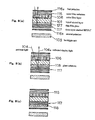
- liquid crystal display device of this embodiment is a construction including, in order from the uppermost layer: first polarizer 116a, color filter substrate 115, color filter layer 106, liquid crystal layer 101, thin-film glass 127, three-layer stacked HPDLC 117, second polarizer 116b, and, at the lowermost layer, backlight unit 103.
- the liquid crystal display device of the present embodiment therefore differs from the liquid crystal display device of the first embodiment in that thin-film glass 127 and three-layer stacked HPDLC 117 are stacked together between liquid crystal layer 101 and second polarizer 116.
- first polarizer 116a contributes to display during reflective display.
- This display mode is known as single-polarizer mode.
- a brighter reflective display can be obtained than by a mode in which two polarizers are used during reflective display.
- a twisted-nematic liquid crystal mode is used as liquid crystal layer 101.
- the design of this twisted-nematic liquid crystal is described in "Analysis of operation mode of reflective liquid crystal display devices" (LIQUID CRYSTALS, 1999. Vol. 26, No. 11, pp. 1573-1578).
- the present embodiment is basically the same as the liquid crystal display device of the first embodiment, and further detailed explanation is therefore omitted.
- color filter substrate 115 having transparent electrodes is aligned with a glass substrate.
- One of the substrates is converted to a thin film to produce thin-film glass 127.
- This conversion to a thin film can be realized by either grinding or chemically etching the glass substrate.
- a thin film such as a polymer film may also be used in place of a glass substrate.
- Liquid crystal is next injected to form liquid crystal layer 101.
- the direction of orientation of the two substrates is then adjusted to form a prescribed twisted-nematic structure, whereby the liquid crystal panel having thin-film glass 127 is completed.
- First polarizer 116a is bonded to the upper surface of the completed liquid crystal panel.
- three-layer stacked HPDLC 117 is bonded to the lower surface of the liquid crystal panel, and further, second polarizer 116 is bonded to the lower surface of three-layer stacked HPDLC 117.
- Backlight unit 103 is then arranged to complete the production of the device.
- FIG. 8(b) shows a construction in which glass118 that has not been converted to a thin film is used instead of thin-film glass 127.
- ambient light 104 is incident from an oblique direction.
- glass substrate 118 is thick and distant from three-layer stacked HPDLC 117, which is the reflection plane
- ambient light 104 that has been transmitted in by R of color filter layer 106 is then transmitted out by neighboring picture element G as reflected display light 104a.
- the problem of parallax occurs.
- thin-film glass 127 must be formed as shown in FIG. 8(a).
- three-layer stacked HPDLC layer 117 may be incorporated between color filter substrate 115 and glass substrate 118, i.e., built into the interior of the liquid crystal panel, as shown in FIG. 8(c).
- the liquid crystal display device of the present embodiment not only eliminates parallax through the use of thin-film glass 127, but can also realize full-color reflective display in bright surroundings and full-color transmissive display in dark surroundings as in the first embodiment by forming, as reflective structural layer 102, a layer that contains liquid crystal or polymer liquid crystal and that takes advantage of Bragg reflection between liquid crystal layer 101 and backlight unit 103.
- FIG. 9 shows a side sectional view of the details of the construction of an example of the liquid crystal display device of the present embodiment
- FIG. 10 shows the basic construction of the liquid crystal display device of the present embodiment.
- the liquid crystal display device of the present embodiment is a construction that includes, in order from the uppermost layer: first polarizer 216a, color filter substrate 215, first color filter layer 206a, liquid crystal layer 201, glass 218, three-layer stacked HPDLC 217, second polarizer 216b , second color filter layer 206b, and, at the lowermost layer, backlight unit 203.
- first color filter layer 206a which is formed on color filter substrate 215
- second color filter layer 206b is formed on a color filter substrate, but for the sake of simplification, the color filter substrate of second color filter layer 206b is not shown in FIG. 9.
- the liquid crystal display device of the present embodiment differs from the liquid crystal display device of the first and second embodiments in that second color filter layer 206b is provided between backlight unit 203 and reflective structural layer 202, which corresponds to three-layer stacked HPDLC 217; i.e., below reflective structural layer 202.
- second color filter layer 206b is provided between backlight unit 203 and reflective structural layer 202, which corresponds to three-layer stacked HPDLC 217; i.e., below reflective structural layer 202.
- the construction is basically the same as that of the first embodiment, and detailed explanation is therefore omitted.
- first color filter layer 206a and second color filter layer 206b are arranged such that each picture element is matched mutually.
- each of picture elements A, B, and C of first color filter layer 206a matches the position of each of picture elements A, B, and C, respectively, of second color filter layer 206b.
- this arrangement allows, for example, during transmissive display, back light beam 205 from backlight unit 203 that is transmitted out by picture element B of second color filter layer 206b to be transmitted by picture element B of first color filter layer 206a.
- each color of A, B, and C is generally selected as red (R), green (G), and blue (B).
- the transmittance and color purity of a color filter are in a reciprocal relationship, and a color filter having high transmittance therefore has low color purity, and a color filter having high color purity has low transmittance.
- a liquid crystal display device has only one color filter layer having this characteristic, light is transmitted by the color filter layer two times during reflective display: at the time of incidence and reflection; and transmitted by the color filter layer only once during transmissive display: as transmissive display light.
- the use of a color filter having high transmittance enables high reflectance to be obtained during reflective display, color purity during transmissive display is low.
- the use of a color filter having low transmittance enables high color purity to be obtained during transmissive display, but reflectance is low during reflective display. It is therefore problematic for a construction having only one color filter layer to obtain both high reflectance during reflective display and high color purity during transmissive display.
- reflected display light 204a is transmitted by only first color filter layer 206a during reflective display as shown in FIG. 10(a), while back light 205 is transmitted by both of second color filter layer 206b and first color filter layer 206a during transmissive display, as shown in FIG. 10(b).
- first color filter layer 206a a layer having high transmittance and low color purity characteristics
- second color filter layer 206b a layer having high transmittance and low color purity
- first color filter layer 206a and second color filter layer 206b enables desired transmittance and color purity to be obtained, whereby higher reflectance during reflective display and higher color purity during transmissive display can be obtained at high level than in a liquid crystal display device of a construction that employs one color filter layer.
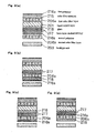
- second color filter layer 206b is basically preferably below reflective structural layer 202, i.e., below three-layer stacked HPDLC 217 in FIG. 9; and as constructions other than that of FIG. 9(a), glass 218 and second polarizer 216b may be arranged as shown in FIG. 9(b) to FIG. 9(d).
- the thin-film glass that was described in the second embodiment can be similarly used to eliminate parallax.
- the liquid crystal display device of the present embodiment as described in the foregoing explanation not only enables higher reflectance during reflective display and higher color purity during transmissive display than a liquid crystal display device of a construction that employs one color filter layer, but also, as with the first and second embodiments, enables full-color reflective display in bright surroundings and full-color transmissive display in dark surroundings by forming a layer that contains liquid crystal or a polymer liquid crystal that uses Bragg reflection as reflective structural layer 202 between liquid crystal layer 201 and backlight unit 203.
- FIG. 11 is a side sectional view showing the details of the construction of an example of a liquid crystal display device of the present embodiment
- FIG. 12 shows the basic construction of the liquid crystal display device of the present embodiment.
- the liquid crystal display device of the present embodiment is of a construction that includes, in order from the uppermost layer: first polarizer 316a, color filter substrate 315, color filter layer 306, liquid crystal layer 301, glass 318, spatially divided reflective structural layer 332 having a plurality of areas that reflect only light of a wavelength that corresponds to each picture element of color filter layer 306, second polarizer 316b, and, as the lowermost layer, backlight unit 303.
- spatially divided reflective structural layer 332 is provided between backlight unit 303 and liquid crystal layer 301, i.e., below liquid crystal layer 301.
- the construction of the present embodiment is basically the same as the first embodiment, and detailed explanation is therefore here omitted.
- the area of spatially divided reflective structural layer 332 is spatially divided so as to correspond to each of picture elements A, B, and C of color filter layer 306, and each of areas A, B, and C of spatially divided reflective structural layer 332 reflects only light of the wavelength band that corresponds to each of picture elements A, B, and C, respectively, of color filter layer 306.
- each of picture elements A, B, and C of color filter layer 306 selects and transmits the wavelength band of red (R), green (G) and blue (B), respectively; and in concert with this action, each of areas A, B, and C of spatially divided reflective structural layer 332 reflects light of only the wavelength bands of red (R), green (G), and blue (B), respectively.
- spatially divided reflective structural layer 332 has characteristics that are combined from the characteristics of the color filter and the characteristics of the reflective structural layer. Further, this spatially divided reflective structural layer 332 can be placed in a transparent state by means of electrical control. Moreover, each of the areas of spatially divided reflective structural layer 332 may be constructed using the above-described HPDLC element or cholesteric liquid crystal layer.
- each reflector (each of areas A, B, and C of spatially divided reflective structural layer 332 in FIG. 12) is arranged in parallel in a direction that is substantially orthogonal to the direction in which liquid crystal layer 301 and backlight unit 303 are stacked with respect to spatially divided reflective structural layer 332, which is the reflective structural layer.
- ambient light 304 is transmitted by color filter layer 306 and liquid crystal layer 301 before reaching spatially divided reflective structural layer 332, as shown in FIG. 12(a).
- This spatially divided reflective structural layer 332 reflects only light of wavelength bands that correspond to the color filter colors.
- a of spatially divided reflective structural layer 332 reflects only light of the wavelength band that corresponds to A of color filter layer 306.
- reflected display light 304a is transmitted by liquid crystal layer 301 and color filter layer 306.
- light during reflective display is transmitted by color filter layer 306 two times.
- light of other wavelength bands is not reflected from spatially divided reflective structural layer 332.
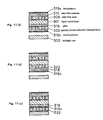
- spatially divided reflective structural layer 332 is basically preferably arranged below liquid crystal layer 301, and as constructions other than the one shown in FIG. 11(a), glass 318 and second polarizer 316b may be arranged as shown in FIG. 11(b) to FIG. 11(c).
- glass 318 and second polarizer 316b may be arranged as shown in FIG. 11(b) to FIG. 11(c).
- full-color display is theoretically possible even if the construction lacks color filter layer 306, and the construction may therefore be provided with color filter layer 306 when a further improvement in color purity is desired or when the color purity of spatially divided reflective structural layer 332 changes due to the viewing angle.
- the liquid crystal display device of the present embodiment can not only obtain, at high level, high reflectance during reflective display and high color purity during transmissive display by means of a simple construction having only one color filter layer 306 through the use of spatially divided reflective structural layer 332, but can realize full-color reflective display in bright surroundings and full-color transmissive display in dark surroundings as in the first and third embodiments by forming, as spatially divided reflective structural layer 332, a layer that uses Bragg reflection and that contains liquid crystal or polymer liquid crystal between liquid crystal layer 301 and backlight unit 303.
- a compensator that is below a first polarizer, which is the uppermost layer, and above a second polarizer may be a stacked component, and further, may be a component that is arranged above the reflective structural layer.
- This compensator enables the use of display elements other than TN liquid crystals such as STN liquid crystal or birefringence liquid crystal as liquid crystal display elements.
- liquid crystal layer of each of the embodiments may be driven by an active matrix, whereby a high contrast ratio can be maintained during reflective and transmissive display with a large display capacity.
Landscapes
- Physics & Mathematics (AREA)
- Nonlinear Science (AREA)
- Chemical & Material Sciences (AREA)
- Mathematical Physics (AREA)
- Crystallography & Structural Chemistry (AREA)
- General Physics & Mathematics (AREA)
- Optics & Photonics (AREA)
- Dispersion Chemistry (AREA)
- Liquid Crystal (AREA)
- Devices For Indicating Variable Information By Combining Individual Elements (AREA)
Abstract
A liquid crystal display device comprising a first polarizing sheet(16a), a
color filter layer(6) formed on glass sheet(18), a second polarizing sheet(16b),
three-layered HPDLC(17) formed below the liquid crystal layer(1) and acting as a
reflective structural layer having a reflectivity changed electrically, and a backlight
unit as the lowermost layer. Each layer of the three-layered HPDLC(17) is
composed of a liquid crystal droplet layer polymer layer and reflects blue, green,
red by Bragg reflection. When voltage is applied to the three-layered HPDLC(17),
the reflectivity of liquid crystal droplet layer of each layer change, so that the
HPDLC can be made transparent by equalizing the reflectivities of the liquid
crystal liquid droplet layer to those of polymer layers.
Description
The present invention relates to a liquid crystal display device for
displaying information.
Reflective liquid crystal displays have come into widespread use in
portable applications due to their low power consumption. In particular, reflective
liquid crystal display devices capable of full-color display are now under
development.
A reflective liquid crystal display device uses ambient light as a light
source and can provide display with high picture quality when used outside in
sunlight, in contrast, the display of a transmissive liquid crystal display device
generally suffers from low contrast and poor visibility when used outside in
sunlight. However, the visibility of a reflective liquid crystal display device is poor
when used outside at night or in a room with poor lighting and cannot obtain the
image quality that is possible in a transmissive liquid crystal display device.
A liquid crystal display device is therefore desired that is capable of
reflective display in a bright setting and that can display using a supplementary
light source in a dark setting. A semi-transmissive liquid crystal display device can
be offered as one example. Such a semi-transmissive liquid crystal display device
employs a reflecting surface that reflects incident light as a semi-transmissive
surface. However, a semi-transmissive surface having, for example, transmittance
of 50% and reflectance of 50% has the disadvantage that display is dark during
both reflective display and transmissive display.
A liquid crystal display device that can be switched between reflective
and transmissive display is disclosed in Japanese Patent Laid-open No. 119026/99
as a device for overcoming the above-described disadvantage. FIG. 13 shows a
schematic side sectional view of a liquid crystal display device that includes a
holographic reflecting layer. As shown in FIG. 13, holographic reflecting layer 528,
which is a volume hologram, is arranged between backlight unit 503 and liquid
crystal layer 501.
This volume hologram is a structure having fixed refractive index
modulation, and when the period of this modulation is at the level of visible
wavelengths, produces diffraction known as Bragg reflection, whereby light of a
particular angle of incidence and a particular wavelength is strongly reflected in a
specific direction. This hologram function and the characteristics of a liquid crystal
display device having a prior-art holographic reflecting layer can be explained
using the circular charts shown in FIG. 14. The radius of the circle shown in FIG.
14(a) is given as n/λ. Here, λ is the wavelength of incident light, and n is the
average refractive index of the hologram medium. The incident light is represented
as a vector from the center to the circumference of the circle. Incident wave
number vector 529 and reciprocal vector 531 are arranged as in FIG. 14(a). The
direction of reciprocal vector 531 is defined as the modulation direction of the
refractive modulation, and the magnitude of the vector is defined as the inverse of
the modulation period. In FIG. 14(a), emitted wave number vector 530 is shown as
the difference between incident wave number vector 529 and reciprocal vector 531.
Light is strongly emitted in the direction of this emitted wave number vector 530.
Explanation next regards the reflective action using FIG. 14(b). During
reflective display, display is realized by only incident light, and backlight unit 503
is not used. Incident light from the surroundings is incident to liquid crystal layer
501 and then incident to holographic reflecting layer 528. If the reciprocal vector of
holographic reflecting layer 528 is arranged as shown in FIG. 14(b), only a specific
wavelength is selectively reflected in a specific emission direction. The light that is
selectively reflected again passes through liquid crystal layer 501 to enable
reflective display. Light of wavelengths other than this selectively reflected
wavelength is transmitted by holographic reflecting layer 528 and therefore does
not contribute to display.
When the surroundings are dark, on the other hand, the backlight is lit up.
In this case, the light from the backlight is transmitted by holographic reflecting
layer 528 and is incident to liquid crystal layer 501, whereby transmissive display
can be realized as shown in FIG. 14(c).
Using the liquid crystal display device that is disclosed in Japanese Patent
Laid-open No. 119026/1999 as described above enables display that switches
between reflective and transmissive display.
Nevertheless, the liquid crystal display device that is disclosed in the
above-described Japanese Patent Laid-open No. 119026/1999 has the disadvantage
that the displayed colors during reflective display differ from the displayed colors
during transmissive display. More specifically, as shown in FIG. 14(b), only light
of a specific wavelength that is determined by the hologram is reflected during
reflective display. And as a result, only monochromatic display is possible during
reflective display. Further, as shown in FIG. 14(c), during transmissive display,
specific wavelengths of the light from the backlight undergo Bragg reflection by
the hologram and cannot contribute to transmissive display. The wavelengths that
are subject to this Bragg reflection are identical to the wavelength of
monochromatic light during reflective display. Thus, even though a color such as
green can be displayed during reflective display, the complementary color of green
must be displayed during transmissive display. For similar reasons, full-color
display is not possible.
Thus, although the liquid crystal display device that is disclosed in
Japanese Patent Laid-open No. 119026/1999 realizes display that can be switched
between reflective and transmissive display, such a display has the disadvantages
that color display is limited and full-color display is not possible.
It is therefore an object of the present invention to provide a liquid crystal
display device that employs Bragg reflection and that can realize full-color
reflective display in bright surroundings and full-color transmissive display in dark
surroundings.
To achieve the above-described object, the liquid crystal display device of
the present invention includes:
The liquid crystal device of the present invention that is constructed as
described above includes a reflective structural layer below the liquid crystal layer,
and this reflective structural layer includes a plurality of reflectors that, by means
of Bragg reflection, reflect only light of a specific frequency band wherein the
reflectance of each reflector can be electrically switched. In other words, the use of
Bragg reflection realizes a liquid crystal display device that allows switching
between reflective and transmissive display that is brighter than a liquid crystal
display device that employs a semi-transmissive surface. Further, full-color display
is possible if each of the reflectors of the reflective structural layer is constructed
such that each of the reflectors, which use Bragg reflection to reflect only light of a
specific frequency band, reflects only blue, or reflects only green, or reflects only
red.
Further, the thickness of at least one of the substrates that sandwich the
liquid crystal layer of the liquid crystal display device of the present invention may
be a thickness that does not produce parallax, and this substrate may be a film
substrate or a thin-film glass.
In addition, the liquid crystal display device of the present invention may
include a first color filter layer that is arranged above the liquid crystal layer, and
further, may include a second color filter layer that is arranged below the reflective
structural layer. In the case of a construction having a second color filter layer in
addition to the first color filter layer in particular, the use of a layer having high
transmittance and low color purity as the first color filter layer and a layer having
high transmittance and low color purity as the second color filter layer enables a
device having characteristics in which high reflectance is obtained during reflective
display and a high color purity is obtained during transmissive display.
Each of the reflectors may be a unit that is formed by stacking in the
direction of stacking of the liquid crystal layer and backlight unit with respect to
the reflective structural layer.
In addition, the reflectors may each be arranged parallel to a direction that
is substantially orthogonal to the direction of stacking of the liquid crystal layer
and backlight unit with respect to the reflective structural layer. In this case, when
reflectors that reflect blue, green and red are each arranged parallel, full-color
display can be realized without providing a color filter, whereby a liquid crystal
display device can be obtained that is both bright and that has a simple construction.
Further, each of the reflectors may contain liquid crystal; and in particular,
may include cholesteric liquid crystal; may be a structure in which one or more
liquid crystal drop layers that contain drops of liquid crystal are alternately stacked
with one or more polymer layers; or may be a polymer layer that contains drops of
cholesteric liquid crystal.
The liquid crystal device of the present invention may include a first
polarizer that is arranged above the liquid crystal layer; and may include a second
polarizer that is arranged below the liquid crystal layer. In addition, the use of a
compensator allows the use of display elements such as STN liquid crystals or
birefringence liquid crystals as the liquid crystal display elements instead of TN
liquid crystals.
The liquid crystal display device of the present invention may include a
compensator for compensating for phase difference that is arranged below the first
polarizer and above the second polarizer; and the compensator may be arranged
above the reflective structural layer.
Finally, the liquid crystal layer may be driven by an active matrix.
Explanation next regards embodiments of the present invention with
reference to the accompanying drawings. In the explanations of each of the
embodiments, holographic polymer dispersed liquid crystal is abbreviated as
"HPDLC."
We first refer to FIG. 1, in which is shown a side sectional view of the
details of the construction of an example of the liquid crystal display device of the
present embodiment.
The liquid crystal display device is of a construction that includes: first
polarizer 16a that formed on the top layer; below first polarizer 16a, color filter
layer 6 that is composed of filters that each transmit only R (red), G (green), or B
(blue) and in which color filter substrate 15 is formed as the upper layer side;
below color filter layer 6, liquid crystal layer 1 that is formed on glass 18 for
projecting image information; second polarizer 16b that is below liquid crystal
layer 1, i.e., below glass 18; three-layer HPDLC 17 having reflectors in which
reflectance can be electrically switched that is arranged below second polarizer 16b,
i.e., that is below liquid crystal layer 1; and then, on the lowest layer, backlight unit
3, which is the lighting for irradiating light from the backside of the liquid crystal
layer 1.
An outline of the method of forming liquid crystal layer 1 is next
described.
Alignment layers are first formed on both of glass substrate 18 having
transparent electrodes and color filter substrate 15 having color filter layer 6 and
transparent electrodes. The transparent electrodes on the two substrates are not
shown in FIG. 1. An alignment process is next carried out on the alignment layers,
and the two substrates are aligned together with spacers interposed. The substrates
are bonded together at this time such that the directions of the alignment processes
of the two substrates are mutually orthogonal. The space between the two
substrates is then filled with a nematic liquid crystal to complete the formation of
liquid crystal layer 1.
The basic principles of the liquid crystal display device of the present
embodiment are next explained using FIG. 2, which shows a schematic side
sectional view of the basic construction of the liquid crystal display device of the
present embodiment.
As shown in FIG. 2(a) and FIG. 2(b), the liquid crystal display device of
the present embodiment takes as its basic structure: liquid crystal layer 1; reflective
structural layer 2, which corresponds to three-layer stacked HPDLC 17; and
backlight unit 3; but, as shown in FIG. 2(c) and FIG. 2(d), may also take as its
basic structure a construction in which color filter layer 6 is formed on the upper
layer of liquid crystal layer 1.
Reflective structural layer 2 may be any construction as long as reflectors
can be reversibly switched between a state in which the light reflectance is high but
transmittance is low and a state in which light transmittance is high but light
reflectance is low; but, as shown below, reflective structural layer 2 is ideally a
construction that contains liquid crystal or polymer liquid crystal that allows
electrical control of reflectance and that takes advantage of Bragg reflection.
For example, reflective structural layer 2 may be alternately stacked
structural layer 9 shown in FIG. 3(a) and FIG. 3(b) in which liquid crystal drop
layers 10, which are the reflectors, and polymer layers 11 are alternately stacked. If
the refractive index of liquid crystal drop layers 10 and polymer layers 11 is
different, ambient light 4 is selectively reflected at a wavelength that is determined
by the period of alternation, as shown in FIG. 3(a). When voltage is applied to this
alternately stacked structural layer 9, the refractive index of liquid crystal drop
layer 10 changes to coincide with the refractive index of polymer layer 11, whereby
the selective reflection is canceled to produce a transparent state, and back light 5
from backlight unit 3 can be transmitted as shown in FIG. 3(b). Alternately stacked
structural layer 9 may also be stacked first alternately stacked structural layer 9a
and second alternately stacked structural layer 9b having different stacking periods,
whereby polychromatic light can be reflected, as shown in FIG. 3(c) and FIG. 3(d).
In other words, the liquid crystal display device of the present embodiment can
realize full-color display if each of a plurality of reflectors such as first alternately
stacked structural layer 9a and second alternately stacked structural layer 9b has a
structure that takes advantage of Bragg reflection to reflect only light of a specific
frequency band.
In addition, a cholesteric liquid crystal may also be used as the reflectors
of reflective structural layer 2. As is known in the art, the use of cholesteric liquid
crystal allows reflectance to be electrically controlled. Since cholesteric liquid
crystal layer 7 has a spiral structure as shown in FIG. 4(a), ambient light 4 that
corresponds to one half the pitch of this spiral structure is selectively reflected.
Moreover, the spiral structure is canceled if voltage is applied to this cholesteric
liquid crystal, as shown in FIG. 4(b), whereby the above-described reflectance is
lost and all wavelengths of back light 5 are transmitted. An example in which this
effect is realized is described in "Switchable mirrors of chiral liquid crystal gels"
(LIQUID CRYSTALS, 1999, Volume 26, No. 11, pp. 1645-1653). Further, the use
of stacked cholesteric liquid crystal layer 8, in which first cholesteric liquid crystal
7a and second cholesteric liquid crystal 7b having different spiral pitches are
stacked, as reflective structural layer 2 as shown in FIG. 4(c) and FIG. 4(d) enables
the reflection of polychromatic light, similar to alternately stacked structural layer
9.
In this way, each reflector of reflective structural layer 2 may be formed
by stacking in the direction in which liquid crystal layer 1 and backlight unit 3 are
stacked with respect to reflective structural layer 2.
Alternatively, reflective structural layer 2 may also be a structure in which
reflectors are constituted by polymer layers that contain cholesteric liquid crystal
drops, as shown in FIG. 5(a) and FIG. 5(b). The application of voltage to polymer
layer 14, which contains cholesteric liquid crystal drops 13 composed of
cholesteric liquid crystal of a spiral pitch that selectively reflects ambient light 4,
cancels the spiral structure in cholesteric liquid crystal drops 13 to produce a
transparent state, thereby allowing transmission of back light 5. Moreover, a
polymer layer that contains cholesteric liquid crystal drops that contain a plurality
of cholesteric liquid crystals of differing spiral pitches can selectively reflect
polychromatic light.
We next refer to FIG. 6 and FIG. 7 to explain details of the structure and a
method of producing the stacked structure of HPDLC, which is alternately stacked
structural layer 9.
First, as shown in FIG. 6(a), liquid crystal/photo-curing substance
composite layer 20, i.e., a layer composed of a composite of liquid crystal and a
photo-sensitive substance, is formed on substrate 19 having transparent electrodes
(not shown in the figure).
Next, as shown in FIG. 6(b), laser light 21 emitted from the same laser is
branched and the two light beams are caused to intersect inside liquid
crystal/photo-curing substance composite layer 20, whereby the laser light
interference causes strong and selective photo-curing in areas where laser intensity
is high. In areas where laser intensity is low, the liquid crystal is separated as liquid
drops. The foregoing process results in HPDLC layer 22 that is composed of a
liquid crystal drop layer and photo-cured polymer layer as shown in FIG. 6(c). A
difference between the refractive indices of the liquid crystal drop layer and
polymer layer results in selective reflection of light of a wavelength that
corresponds to the stacking period of the alternately stacked structure. Photo-curing
is next carried out in a nitrogen atmosphere or under reduced pressure if the photo-curing
substance is impeded by oxygen. The stacking period of this alternately
stacked structure can be determined by the wavelength of the laser light and the
angle of intersection. If a liquid crystal/photo-curing substance composite layer is
again formed on completed HPDLC layer 22 of FIG. 6(c) and exposed at an altered
laser wavelength and intersection angle, an HPDLC layer having two layers of
different alternately stacking periods can be obtained. If the above-described layer
formation and exposure are carried out, for example, three times, the HPDLC layer
can be made a three-layer stacked HPDLC layer 17 that is composed of Blue
HPDLC 23 for reflecting blue, Green HPDLC 24 for reflecting green, and Red
HPDLC 25 for reflecting red, as shown in FIG. 7. In this case, transparent
electrodes 26 are electrically connected to Blue HPDLC 23 and Red HPDLC 25.
When stacking, the order of stacking is preferably blue, green and red if
light is incident from the upper surface of the stacked layers. This order is preferred
because light is more easily scattered with shorter wavelengths. This three-layer
stacked HPDLC layer 17 reflects white light. Applying voltage to this three-layer
stacked HPDLC layer 17 causes the refractive index of the liquid crystal drop layer
to change. If the refractive index of the liquid crystal drop layer matches that of the
polymer layer, the selective light reflection is canceled to produce a transparent
state.
In the present embodiment, the reflectance of three-layer stacked HPDLC
layer 17 is high when voltage is not applied. Accordingly, display operation is
enabled by supplying voltage to only liquid crystal layer 1 without supplying
voltage to three-layer stacked HPDLC layer 17, and extra power is therefore not
needed during reflective display. In addition, transmissive display can be obtained
by supplying voltage to stacked HPDLC layer 22 to produce a transparent state and
lighting up backlight unit 3.
According to the liquid crystal display device of the present embodiment
as described in the foregoing explanation, a layer that contains polymer liquid
crystal or liquid crystal that uses Bragg reflection is formed as reflective structural
layer 2 between liquid crystal layer 1 and backlight unit 3 to enable full color
reflective display in bright surroundings and full-color transmissive display in dark
surroundings.
We next refer to FIG. 8, in which is shown a side sectional view showing
the details of the construction of an example of a liquid crystal display device of
the present embodiment.
As shown in FIG. 8(a), liquid crystal display device of this embodiment is
a construction including, in order from the uppermost layer: first polarizer 116a,
color filter substrate 115, color filter layer 106, liquid crystal layer 101, thin-film
glass 127, three-layer stacked HPDLC 117, second polarizer 116b, and, at the
lowermost layer, backlight unit 103.
The liquid crystal display device of the present embodiment therefore
differs from the liquid crystal display device of the first embodiment in that thin-film
glass 127 and three-layer stacked HPDLC 117 are stacked together between
liquid crystal layer 101 and second polarizer 116.
Further, in the liquid crystal display device of the present embodiment,
only first polarizer 116a contributes to display during reflective display. This
display mode is known as single-polarizer mode. A brighter reflective display can
be obtained than by a mode in which two polarizers are used during reflective
display. At this time, a twisted-nematic liquid crystal mode is used as liquid crystal
layer 101. The design of this twisted-nematic liquid crystal is described in
"Analysis of operation mode of reflective liquid crystal display devices" (LIQUID
CRYSTALS, 1999. Vol. 26, No. 11, pp. 1573-1578).
Apart from the above-described points, the present embodiment is
basically the same as the liquid crystal display device of the first embodiment, and
further detailed explanation is therefore omitted.
A summary of the procedures for producing a liquid crystal display device
of the present embodiment is next described.
As with the first embodiment, color filter substrate 115 having transparent
electrodes is aligned with a glass substrate. One of the substrates is converted to a
thin film to produce thin-film glass 127. This conversion to a thin film can be
realized by either grinding or chemically etching the glass substrate. Clearly, a thin
film such as a polymer film may also be used in place of a glass substrate. Liquid
crystal is next injected to form liquid crystal layer 101. The direction of orientation
of the two substrates is then adjusted to form a prescribed twisted-nematic structure,
whereby the liquid crystal panel having thin-film glass 127 is completed. First
polarizer 116a is bonded to the upper surface of the completed liquid crystal panel.
In addition, three-layer stacked HPDLC 117 is bonded to the lower surface of the
liquid crystal panel, and further, second polarizer 116 is bonded to the lower
surface of three-layer stacked HPDLC 117. Backlight unit 103 is then arranged to
complete the production of the device.
Next, regarding the reason for using thin-film glass 127, we refer to FIG.
8(b). FIG. 8(b) shows a construction in which glass118 that has not been
converted to a thin film is used instead of thin-film glass 127. During reflective
display, ambient light 104 is incident from an oblique direction. Thus, when glass
substrate 118 is thick and distant from three-layer stacked HPDLC 117, which is
the reflection plane, ambient light 104 that has been transmitted in by R of color
filter layer 106 is then transmitted out by neighboring picture element G as
reflected display light 104a. In other words, the problem of parallax occurs. To
prevent this problem of parallax, thin-film glass 127 must be formed as shown in
FIG. 8(a).
To prevent reflective display light leakage from a neighboring picture
element, three-layer stacked HPDLC layer 117 may be incorporated between color
filter substrate 115 and glass substrate 118, i.e., built into the interior of the liquid
crystal panel, as shown in FIG. 8(c).
The liquid crystal display device of the present embodiment according to
the foregoing explanation not only eliminates parallax through the use of thin-film
glass 127, but can also realize full-color reflective display in bright surroundings
and full-color transmissive display in dark surroundings as in the first embodiment
by forming, as reflective structural layer 102, a layer that contains liquid crystal or
polymer liquid crystal and that takes advantage of Bragg reflection between liquid
crystal layer 101 and backlight unit 103.
FIG. 9 shows a side sectional view of the details of the construction of an
example of the liquid crystal display device of the present embodiment, and FIG.
10 shows the basic construction of the liquid crystal display device of the present
embodiment.
As shown in FIG. 9(a), the liquid crystal display device of the present
embodiment is a construction that includes, in order from the uppermost layer: first
polarizer 216a, color filter substrate 215, first color filter layer 206a, liquid crystal
layer 201, glass 218, three-layer stacked HPDLC 217, second polarizer 216b ,
second color filter layer 206b, and, at the lowermost layer, backlight unit 203. As
with first color filter layer 206a, which is formed on color filter substrate 215,
second color filter layer 206b is formed on a color filter substrate, but for the sake
of simplification, the color filter substrate of second color filter layer 206b is not
shown in FIG. 9.
As shown in FIG. 10, the liquid crystal display device of the present
embodiment differs from the liquid crystal display device of the first and second
embodiments in that second color filter layer 206b is provided between backlight
unit 203 and reflective structural layer 202, which corresponds to three-layer
stacked HPDLC 217; i.e., below reflective structural layer 202. Apart from the
above-described difference, the construction is basically the same as that of the
first embodiment, and detailed explanation is therefore omitted.
In the case of the present embodiment, first color filter layer 206a and
second color filter layer 206b are arranged such that each picture element is
matched mutually. In other words, each of picture elements A, B, and C of first
color filter layer 206a matches the position of each of picture elements A, B, and C,
respectively, of second color filter layer 206b. As shown in FIG. 10(b), this
arrangement allows, for example, during transmissive display, back light beam 205
from backlight unit 203 that is transmitted out by picture element B of second color
filter layer 206b to be transmitted by picture element B of first color filter layer
206a. For full-color display, each color of A, B, and C is generally selected as red
(R), green (G), and blue (B).
Meanwhile, the transmittance and color purity of a color filter are in a
reciprocal relationship, and a color filter having high transmittance therefore has
low color purity, and a color filter having high color purity has low transmittance.
When a liquid crystal display device has only one color filter layer having this
characteristic, light is transmitted by the color filter layer two times during
reflective display: at the time of incidence and reflection; and transmitted by the
color filter layer only once during transmissive display: as transmissive display
light. As a result, although the use of a color filter having high transmittance
enables high reflectance to be obtained during reflective display, color purity
during transmissive display is low. Conversely, the use of a color filter having low
transmittance enables high color purity to be obtained during transmissive display,
but reflectance is low during reflective display. It is therefore problematic for a
construction having only one color filter layer to obtain both high reflectance
during reflective display and high color purity during transmissive display.
In the construction of the present embodiment, reflected display light
204a is transmitted by only first color filter layer 206a during reflective display as
shown in FIG. 10(a), while back light 205 is transmitted by both of second color
filter layer 206b and first color filter layer 206a during transmissive display, as
shown in FIG. 10(b). Thus, for example, if a layer having high transmittance and
low color purity characteristics is used as first color filter layer 206a and a layer
having high transmittance and low color purity is used as second color filter layer
206b, a display having the characteristics of high reflectance during reflective
display and high color purity during transmissive display can be obtained. In
addition, a variety of combinations of the reflectance and color purity
characteristics of first color filter layer 206a and second color filter layer 206b
enables desired transmittance and color purity to be obtained, whereby higher
reflectance during reflective display and higher color purity during transmissive
display can be obtained at high level than in a liquid crystal display device of a
construction that employs one color filter layer.
In the construction of a liquid crystal display device of the present
embodiment, second color filter layer 206b is basically preferably below reflective
structural layer 202, i.e., below three-layer stacked HPDLC 217 in FIG. 9; and as
constructions other than that of FIG. 9(a), glass 218 and second polarizer 216b may
be arranged as shown in FIG. 9(b) to FIG. 9(d). Alternatively, it should be clear
that the thin-film glass that was described in the second embodiment can be
similarly used to eliminate parallax.
The liquid crystal display device of the present embodiment as described
in the foregoing explanation not only enables higher reflectance during reflective
display and higher color purity during transmissive display than a liquid crystal
display device of a construction that employs one color filter layer, but also, as
with the first and second embodiments, enables full-color reflective display in
bright surroundings and full-color transmissive display in dark surroundings by
forming a layer that contains liquid crystal or a polymer liquid crystal that uses
Bragg reflection as reflective structural layer 202 between liquid crystal layer 201
and backlight unit 203.
FIG. 11 is a side sectional view showing the details of the construction of
an example of a liquid crystal display device of the present embodiment, and FIG.
12 shows the basic construction of the liquid crystal display device of the present
embodiment.
As shown in FIG. 11(a), the liquid crystal display device of the present
embodiment is of a construction that includes, in order from the uppermost layer:
first polarizer 316a, color filter substrate 315, color filter layer 306, liquid crystal
layer 301, glass 318, spatially divided reflective structural layer 332 having a
plurality of areas that reflect only light of a wavelength that corresponds to each
picture element of color filter layer 306, second polarizer 316b, and, as the
lowermost layer, backlight unit 303.
As shown in FIG. 12, in the liquid crystal display device of the present
embodiment, spatially divided reflective structural layer 332 is provided between
backlight unit 303 and liquid crystal layer 301, i.e., below liquid crystal layer 301.
Apart from this point, the construction of the present embodiment is basically the
same as the first embodiment, and detailed explanation is therefore here omitted.
As shown in FIG. 12(a), the area of spatially divided reflective structural
layer 332 is spatially divided so as to correspond to each of picture elements A, B,
and C of color filter layer 306, and each of areas A, B, and C of spatially divided
reflective structural layer 332 reflects only light of the wavelength band that
corresponds to each of picture elements A, B, and C, respectively, of color filter
layer 306. During full-color display, each of picture elements A, B, and C of color
filter layer 306 selects and transmits the wavelength band of red (R), green (G) and
blue (B), respectively; and in concert with this action, each of areas A, B, and C of
spatially divided reflective structural layer 332 reflects light of only the wavelength
bands of red (R), green (G), and blue (B), respectively. In other words, spatially
divided reflective structural layer 332 has characteristics that are combined from
the characteristics of the color filter and the characteristics of the reflective
structural layer. Further, this spatially divided reflective structural layer 332 can be
placed in a transparent state by means of electrical control. Moreover, each of the
areas of spatially divided reflective structural layer 332 may be constructed using
the above-described HPDLC element or cholesteric liquid crystal layer.
The spatial division described above means that each reflector (each of
areas A, B, and C of spatially divided reflective structural layer 332 in FIG. 12) is
arranged in parallel in a direction that is substantially orthogonal to the direction in
which liquid crystal layer 301 and backlight unit 303 are stacked with respect to
spatially divided reflective structural layer 332, which is the reflective structural
layer.
In the above-described construction, during reflective display, ambient
light 304 is transmitted by color filter layer 306 and liquid crystal layer 301 before
reaching spatially divided reflective structural layer 332, as shown in FIG. 12(a).
This spatially divided reflective structural layer 332 reflects only light of
wavelength bands that correspond to the color filter colors. In FIG. 12(a), A of
spatially divided reflective structural layer 332 reflects only light of the wavelength
band that corresponds to A of color filter layer 306. After reflection, reflected
display light 304a is transmitted by liquid crystal layer 301 and color filter layer
306. As a result, light during reflective display is transmitted by color filter layer
306 two times. However, light of other wavelength bands is not reflected from
spatially divided reflective structural layer 332. Mixing with colors of other
wavelength bands therefore does not occur and the color purity does not drop even
if a layer of low transmittance is used in color filter layer 306. In addition, if
electrical control of spatially divided reflective structural layer 332 is applied to
produce a transparent state, back light 305 from backlight unit 303 can be
transmitted by spatially divided reflective structural layer 332 and full-color
transmissive display can be realized, as shown in FIG. 12(b).
In the construction of the liquid crystal display device of the present
embodiment, spatially divided reflective structural layer 332 is basically preferably
arranged below liquid crystal layer 301, and as constructions other than the one
shown in FIG. 11(a), glass 318 and second polarizer 316b may be arranged as
shown in FIG. 11(b) to FIG. 11(c). In addition, it goes without saying that parallax
is eliminated if the thin-film glass described in the second embodiment is similarly
used.
In the case of the present embodiment, full-color display is theoretically
possible even if the construction lacks color filter layer 306, and the construction
may therefore be provided with color filter layer 306 when a further improvement
in color purity is desired or when the color purity of spatially divided reflective
structural layer 332 changes due to the viewing angle.
As described in the foregoing explanation, the liquid crystal display
device of the present embodiment can not only obtain, at high level, high
reflectance during reflective display and high color purity during transmissive
display by means of a simple construction having only one color filter layer 306
through the use of spatially divided reflective structural layer 332, but can realize
full-color reflective display in bright surroundings and full-color transmissive
display in dark surroundings as in the first and third embodiments by forming, as
spatially divided reflective structural layer 332, a layer that uses Bragg reflection
and that contains liquid crystal or polymer liquid crystal between liquid crystal
layer 301 and backlight unit 303.
In the liquid crystal display devices of each of the above-described
embodiments, a compensator that is below a first polarizer, which is the uppermost
layer, and above a second polarizer may be a stacked component, and further, may
be a component that is arranged above the reflective structural layer. The use of
this compensator enables the use of display elements other than TN liquid crystals
such as STN liquid crystal or birefringence liquid crystal as liquid crystal display
elements.
In addition, the liquid crystal layer of each of the embodiments may be
driven by an active matrix, whereby a high contrast ratio can be maintained during
reflective and transmissive display with a large display capacity.
Claims (17)
- A liquid crystal display device comprisinga liquid crystal layer;a reflective structural layer that is arranged below said liquid crystal layer and that includes a plurality of reflectors for reflecting only light of specific frequency bands by means of Bragg reflection, wherein reflectance of each of said reflectors can be electrically switched; anda backlight unit that is arranged at the lowermost layer for irradiating light from the backside of the liquid crystal layer.
- A liquid crystal display device according to claim 1, wherein the thickness of at least one of the substrates that sandwich said liquid crystal layer is a thickness that does not produce parallax.
- A liquid crystal display device according to claim 2, wherein said substrate is a thin-film glass.
- A liquid crystal display device according to claim 2, wherein said substrate is a film substrate.
- A liquid crystal display device according to claim 1, further comprising a first color filter layer that is arranged above said liquid crystal layer.
- A liquid crystal display device according to claim 5, further comprising a second color filter layer that is arranged below said reflective structural layer.
- A liquid crystal display device according to claim 1, wherein each of said reflectors is formed by stacking in the direction of stacking of said liquid crystal layer and said backlight unit with respect to said reflective structural layer.
- A liquid crystal display device according to claim 1, wherein each of said reflectors is arranged parallel to a direction that is substantially orthogonal to the direction of stacking of said liquid crystal layer and said backlight unit with respect to said reflective structural layer.
- A liquid crystal display device according to claim 1, wherein each of said reflectors contains liquid crystal.
- A liquid crystal display device according to claim 9, wherein each of said reflectors contains cholesteric liquid crystal.
- A liquid crystal display device according to claim 9, wherein each of said reflectors is a construction in which one or more liquid crystal drop layers that contain drops of liquid crystal are alternately stacked with one or more polymer layers.
- A liquid crystal display device according to claim 9, wherein each of said reflectors is composed of a polymer layer containing drops of cholesteric liquid crystal.
- A liquid crystal display device according to claim 1, further comprising a first polarizer that is arranged above said liquid crystal layer.
- A liquid crystal display device according to claim 13, further comprising a second polarizer that is arranged below said liquid crystal layer.
- A liquid crystal display device according to claim 14, further comprising a compensator for compensating phase difference that is arranged below said first polarizer and above said second polarizer.
- A liquid crystal display device according to claim 15, wherein said compensator is arranged above said reflective structural layer.
- A liquid crystal display device according to claim 1, wherein said liquid crystal layer is driven by an active matrix.
Applications Claiming Priority (3)
| Application Number | Priority Date | Filing Date | Title |
|---|---|---|---|
| JP2000209802 | 2000-07-11 | ||
| JP2000209802A JP4412441B2 (en) | 2000-07-11 | 2000-07-11 | Liquid crystal display |
| PCT/JP2001/005934 WO2002005020A1 (en) | 2000-07-11 | 2001-07-09 | Liquid crystal display device |
Publications (2)
| Publication Number | Publication Date |
|---|---|
| EP1312972A1 true EP1312972A1 (en) | 2003-05-21 |
| EP1312972A4 EP1312972A4 (en) | 2006-10-04 |
Family
ID=18706157
Family Applications (1)
| Application Number | Title | Priority Date | Filing Date |
|---|---|---|---|
| EP01947923A Withdrawn EP1312972A4 (en) | 2000-07-11 | 2001-07-09 | Liquid crystal display device |
Country Status (5)
| Country | Link |
|---|---|
| US (1) | US6842209B2 (en) |
| EP (1) | EP1312972A4 (en) |
| JP (1) | JP4412441B2 (en) |
| TW (1) | TW528910B (en) |
| WO (1) | WO2002005020A1 (en) |
Cited By (5)
| Publication number | Priority date | Publication date | Assignee | Title |
|---|---|---|---|---|
| EP1668619A1 (en) * | 2003-09-23 | 2006-06-14 | Koninklijke Philips Electronics N.V. | Electrooptic / micromechanical display with discretely controllable bistable transflector |
| WO2015096380A1 (en) * | 2013-12-25 | 2015-07-02 | 京东方科技集团股份有限公司 | Display substrate and preparation method thereof |
| WO2017139179A1 (en) * | 2016-02-12 | 2017-08-17 | Microsoft Technology Licensing, Llc | Integrated privacy display filtering |
| GB2550460A (en) * | 2016-03-30 | 2017-11-22 | Motorola Mobility Llc | Display construct with intergrated switchable mirror and corresponding systems and methods |
| CN112241088A (en) * | 2020-10-15 | 2021-01-19 | Tcl华星光电技术有限公司 | Miniature light-emitting diode lamp panel, backlight module and preparation method thereof |
Families Citing this family (62)
| Publication number | Priority date | Publication date | Assignee | Title |
|---|---|---|---|---|
| JP3941561B2 (en) * | 2001-09-14 | 2007-07-04 | 三菱電機株式会社 | Double-sided display type liquid crystal display device and information equipment |
| JP3827587B2 (en) * | 2002-02-07 | 2006-09-27 | Nec液晶テクノロジー株式会社 | Reflective or transflective liquid crystal display device |
| US7436470B2 (en) * | 2002-07-06 | 2008-10-14 | Spyder Navigations L.L.C. | Display device having liquid crystal layer and switchable optical layer |
| KR100904521B1 (en) * | 2002-10-31 | 2009-06-25 | 엘지디스플레이 주식회사 | Liquid crystal display with cholesteric liquid crystal color filter |
| US7221417B2 (en) * | 2002-12-26 | 2007-05-22 | Citizen Watch Co., Ltd. | Liquid crystal display device and method for manufacturing the same |
| JP2004279669A (en) * | 2003-03-14 | 2004-10-07 | Sharp Corp | Display system |
| US6894750B2 (en) | 2003-05-01 | 2005-05-17 | Motorola Inc. | Transflective color liquid crystal display with internal rear polarizer |
| US7724321B2 (en) | 2004-09-24 | 2010-05-25 | Epistar Corporation | Liquid crystal display |
| KR100765434B1 (en) | 2006-07-27 | 2007-10-09 | (재)대구경북과학기술연구원 | Transflective display unit |
| JP4747053B2 (en) | 2006-08-15 | 2011-08-10 | Nec液晶テクノロジー株式会社 | Liquid crystal display element and electronic device equipped with the same |
| CN100468163C (en) * | 2006-12-26 | 2009-03-11 | 友达光电股份有限公司 | Liquid crystal display device with a light guide plate |
| WO2010045364A1 (en) * | 2008-10-14 | 2010-04-22 | Real D | Lenticular display systems with offset color filter array |
| WO2011075134A1 (en) * | 2009-12-18 | 2011-06-23 | Hewlett-Packard Development Company, L.P. | Reflective display |
| CN102411225B (en) * | 2010-09-17 | 2015-02-25 | 上海天马微电子有限公司 | Liquid crystal display device and driving mode thereof |
| WO2013031361A1 (en) * | 2011-09-01 | 2013-03-07 | シャープ株式会社 | Liquid-crystal display panel and liquid-crystal display device |
| KR20130037435A (en) * | 2011-10-06 | 2013-04-16 | 삼성전자주식회사 | Transmissive and reflective mode convertible display |
| US20130148055A1 (en) * | 2011-12-08 | 2013-06-13 | E Ink Holdings Inc. | Reflective display |
| US9025112B2 (en) * | 2012-02-02 | 2015-05-05 | Apple Inc. | Display with color mixing prevention structures |
| TWI636283B (en) | 2012-05-18 | 2018-09-21 | 美商瑞爾D斯帕克有限責任公司 | Directional backlight, directional display device and control method thereof |
| US9188731B2 (en) | 2012-05-18 | 2015-11-17 | Reald Inc. | Directional backlight |
| US9678267B2 (en) | 2012-05-18 | 2017-06-13 | Reald Spark, Llc | Wide angle imaging directional backlights |
| US9235057B2 (en) | 2012-05-18 | 2016-01-12 | Reald Inc. | Polarization recovery in a directional display device |
| CN104380185B (en) | 2012-05-18 | 2017-07-28 | 瑞尔D斯帕克有限责任公司 | Directional backlight |
| CN102929028B (en) * | 2012-11-02 | 2017-03-08 | 京东方科技集团股份有限公司 | A kind of liquid crystal indicator |
| BR112015020160B1 (en) | 2013-02-22 | 2022-01-18 | Reald Spark, Llc | DIRECTIONAL BACKLIGHTING |
| EP3011734A4 (en) | 2013-06-17 | 2017-02-22 | RealD Inc. | Controlling light sources of a directional backlight |
| WO2015057588A1 (en) | 2013-10-14 | 2015-04-23 | Reald Inc. | Light input for directional backlight |
| EP3058562A4 (en) | 2013-10-14 | 2017-07-26 | RealD Spark, LLC | Control of directional display |
| US11067736B2 (en) | 2014-06-26 | 2021-07-20 | Reald Spark, Llc | Directional privacy display |
| US9835792B2 (en) | 2014-10-08 | 2017-12-05 | Reald Spark, Llc | Directional backlight |
| WO2016105541A1 (en) | 2014-12-24 | 2016-06-30 | Reald Inc. | Adjustment of perceived roundness in stereoscopic image of a head |
| KR102292616B1 (en) * | 2015-01-22 | 2021-08-24 | 삼성디스플레이 주식회사 | Liquid Crystal Display Device Having Dual Color Filter Pattern and Method for Preparing the Same |
| RU2596062C1 (en) | 2015-03-20 | 2016-08-27 | Автономная Некоммерческая Образовательная Организация Высшего Профессионального Образования "Сколковский Институт Науки И Технологий" | Method for correction of eye image using machine learning and method of machine learning |
| WO2016168305A1 (en) | 2015-04-13 | 2016-10-20 | Reald Inc. | Wide angle imaging directional backlights |
| US10228505B2 (en) | 2015-05-27 | 2019-03-12 | Reald Spark, Llc | Wide angle imaging directional backlights |
| EP3313418B1 (en) | 2015-06-26 | 2024-03-13 | Cerus Corporation | Cryoprecipitate compositions and methods of preparation thereof |
| JP6687349B2 (en) * | 2015-09-11 | 2020-04-22 | エルジー ディスプレイ カンパニー リミテッド | Liquid crystal display |
| KR102521487B1 (en) * | 2015-09-15 | 2023-04-14 | 삼성전자주식회사 | Smart window system and control method of the same |
| CN204964945U (en) * | 2015-09-23 | 2016-01-13 | 京东方科技集团股份有限公司 | Display device |
| CN108351951B (en) | 2015-10-26 | 2023-02-07 | 瑞尔D斯帕克有限责任公司 | Intelligent privacy system, equipment and method thereof |
| US10459321B2 (en) | 2015-11-10 | 2019-10-29 | Reald Inc. | Distortion matching polarization conversion systems and methods thereof |
| WO2017083041A1 (en) | 2015-11-13 | 2017-05-18 | Reald Inc. | Wide angle imaging directional backlights |
| US10359561B2 (en) | 2015-11-13 | 2019-07-23 | Reald Spark, Llc | Waveguide comprising surface relief feature and directional backlight, directional display device, and directional display apparatus comprising said waveguide |
| CN108463787B (en) | 2016-01-05 | 2021-11-30 | 瑞尔D斯帕克有限责任公司 | Gaze correction of multi-perspective images |
| US11079619B2 (en) | 2016-05-19 | 2021-08-03 | Reald Spark, Llc | Wide angle imaging directional backlights |
| EP4124795B1 (en) | 2016-05-23 | 2024-04-10 | RealD Spark, LLC | Wide angle imaging directional backlights |
| US20190369087A1 (en) | 2016-12-23 | 2019-12-05 | Cerus Corporation | Systems and methods for testing and screening using compound bound substrates |
| WO2018129059A1 (en) | 2017-01-04 | 2018-07-12 | Reald Spark, Llc | Optical stack for imaging directional backlights |
| CA3055203A1 (en) | 2017-03-03 | 2018-09-07 | Cerus Corporation | Kits and methods for preparing pathogen-inactivated platelet compositions |
| WO2018187154A1 (en) | 2017-04-03 | 2018-10-11 | Reald Spark, Llc | Segmented imaging directional backlights |
| EP4293574A3 (en) | 2017-08-08 | 2024-04-03 | RealD Spark, LLC | Adjusting a digital representation of a head region |
| US11070791B2 (en) | 2017-11-06 | 2021-07-20 | Reald Spark, Llc | Privacy display apparatus |
| AU2018395525B2 (en) | 2017-12-29 | 2023-09-14 | Cerus Corporation | Systems and methods for treating biological fluids |
| EP3743766B1 (en) | 2018-01-25 | 2026-02-11 | RealD Spark, LLC | Touch screen for privacy display |
| JP7571063B2 (en) | 2019-06-22 | 2024-10-22 | シーラス コーポレイション | Systems and methods for performing biological fluid treatment - Patents.com |
| US12011510B2 (en) | 2019-06-22 | 2024-06-18 | Cerus Corporation | Biological fluid treatment systems |
| CN114269394A (en) | 2019-06-28 | 2022-04-01 | 塞鲁斯公司 | System and method for implementing a biological fluid treatment device |
| EP4214441A4 (en) | 2020-09-16 | 2024-08-28 | RealD Spark, LLC | VEHICLE EXTERIOR LIGHTING DEVICE |
| US12585094B2 (en) | 2022-06-22 | 2026-03-24 | Reald Spark, Llc | Anamorphic directional illumination device |
| WO2024030274A1 (en) | 2022-08-02 | 2024-02-08 | Reald Spark, Llc | Pupil tracking near-eye display |
| CN119948379A (en) | 2022-08-11 | 2025-05-06 | 瑞尔D斯帕克有限责任公司 | Deformable directional lighting device |
| JP7718626B1 (en) * | 2024-02-05 | 2025-08-05 | 源奇科技股▲ふん▼有限公司 | See-through display, electrically controlled eyewear and its system |
Family Cites Families (26)
| Publication number | Priority date | Publication date | Assignee | Title |
|---|---|---|---|---|
| US4059916A (en) * | 1975-01-30 | 1977-11-29 | Copal Company Limited | Light diffusing device |
| EP0246842B1 (en) * | 1986-05-19 | 1998-09-23 | Seiko Epson Corporation | A liquid crystal display device |
| TW218040B (en) * | 1990-09-07 | 1993-12-21 | Sharp Kk | |
| EP0677173B1 (en) * | 1993-11-01 | 2001-10-17 | Motorola, Inc. | Liquid crystal display device comprising reflective holographic optical element |
| US5668649A (en) * | 1994-03-07 | 1997-09-16 | Hitachi, Ltd. | Structure of liquid crystal display device for antireflection |
| JPH0876104A (en) | 1994-09-02 | 1996-03-22 | Citizen Watch Co Ltd | Liquid crystal display panel |
| JP3071658B2 (en) * | 1994-11-02 | 2000-07-31 | シャープ株式会社 | Liquid crystal display device |
| JPH08179320A (en) * | 1994-12-27 | 1996-07-12 | Nippon Telegr & Teleph Corp <Ntt> | Display device |
| JPH08304848A (en) | 1995-04-28 | 1996-11-22 | Sharp Corp | Reflective color liquid crystal display |
| US5686979A (en) * | 1995-06-26 | 1997-11-11 | Minnesota Mining And Manufacturing Company | Optical panel capable of switching between reflective and transmissive states |
| JPH0980432A (en) | 1995-09-14 | 1997-03-28 | Citizen Watch Co Ltd | Liquid crystal display panel |
| US5745203A (en) * | 1996-03-28 | 1998-04-28 | Motorola, Inc. | Liquid crystal display device including multiple ambient light illumination modes with switchable holographic optical element |
| US5841494A (en) * | 1996-06-26 | 1998-11-24 | Hall; Dennis R. | Transflective LCD utilizing chiral liquid crystal filter/mirrors |
| JP3215339B2 (en) * | 1997-01-24 | 2001-10-02 | シャープ株式会社 | Liquid crystal display |
| JPH10253948A (en) | 1997-03-12 | 1998-09-25 | Sony Corp | Liquid crystal display device and liquid crystal display control method |
| JPH11119026A (en) | 1997-10-17 | 1999-04-30 | Toppan Printing Co Ltd | Holographic reflector and reflective liquid crystal display using the same |
| JPH11142810A (en) | 1997-11-12 | 1999-05-28 | Nintendo Co Ltd | Portable information processor |
| JPH11249108A (en) * | 1998-03-04 | 1999-09-17 | Seiko Epson Corp | Liquid crystal devices and electronic equipment |
| JPH11316373A (en) * | 1998-05-06 | 1999-11-16 | Seiko Instruments Inc | Reflection type liquid crystal display |
| JP2000122059A (en) | 1998-10-15 | 2000-04-28 | Toshiba Corp | Liquid crystal display device |
| JP2000131684A (en) * | 1998-10-22 | 2000-05-12 | Toshiba Corp | Liquid crystal display device |
| US6727967B2 (en) * | 1998-10-15 | 2004-04-27 | Kabushiki Kaisha Toshiba | Transelective lcd in which reflected light passes through color filters twice, transmitted light passes through color filter only once, but also passes through additional layer of cholesteric liquid crystal or band-pass filter |
| JP2000258760A (en) * | 1999-03-12 | 2000-09-22 | Toshiba Corp | Liquid crystal display |
| JP2001004997A (en) * | 1999-06-17 | 2001-01-12 | Matsushita Electric Ind Co Ltd | Liquid crystal display |
| US6570633B1 (en) * | 1999-06-21 | 2003-05-27 | Eastman Kodak Company | Multi-layer neutral density sheet having a plurality of light-modulating layers with memory properties |
| US6690438B2 (en) * | 2001-04-06 | 2004-02-10 | Citizen Watch Co., Ltd. | Liquid crystal display panel |
-
2000
- 2000-07-11 JP JP2000209802A patent/JP4412441B2/en not_active Expired - Fee Related
-
2001
- 2001-07-09 EP EP01947923A patent/EP1312972A4/en not_active Withdrawn
- 2001-07-09 US US10/332,472 patent/US6842209B2/en not_active Expired - Fee Related
- 2001-07-09 WO PCT/JP2001/005934 patent/WO2002005020A1/en not_active Ceased
- 2001-07-09 TW TW090116756A patent/TW528910B/en not_active IP Right Cessation
Cited By (9)
| Publication number | Priority date | Publication date | Assignee | Title |
|---|---|---|---|---|
| EP1668619A1 (en) * | 2003-09-23 | 2006-06-14 | Koninklijke Philips Electronics N.V. | Electrooptic / micromechanical display with discretely controllable bistable transflector |
| WO2015096380A1 (en) * | 2013-12-25 | 2015-07-02 | 京东方科技集团股份有限公司 | Display substrate and preparation method thereof |
| US9543545B2 (en) | 2013-12-25 | 2017-01-10 | Boe Technology Group Co., Ltd. | Display substrate with bragg reflection unit for each of the display units of at least three primary colors |
| WO2017139179A1 (en) * | 2016-02-12 | 2017-08-17 | Microsoft Technology Licensing, Llc | Integrated privacy display filtering |
| US11016336B2 (en) | 2016-02-12 | 2021-05-25 | Microsoft Technology Licensing, Llc | Bragg grating-based display filtering |
| GB2550460A (en) * | 2016-03-30 | 2017-11-22 | Motorola Mobility Llc | Display construct with intergrated switchable mirror and corresponding systems and methods |
| US10585307B2 (en) | 2016-03-30 | 2020-03-10 | Motorola Mobility Llc | Display construct with integrated switchable mirror and corresponding systems and methods |
| CN112241088A (en) * | 2020-10-15 | 2021-01-19 | Tcl华星光电技术有限公司 | Miniature light-emitting diode lamp panel, backlight module and preparation method thereof |
| CN112241088B (en) * | 2020-10-15 | 2021-09-03 | Tcl华星光电技术有限公司 | Miniature light-emitting diode lamp panel, backlight module and preparation method thereof |
Also Published As
| Publication number | Publication date |
|---|---|
| US6842209B2 (en) | 2005-01-11 |
| US20040021809A1 (en) | 2004-02-05 |
| EP1312972A4 (en) | 2006-10-04 |
| WO2002005020A1 (en) | 2002-01-17 |
| TW528910B (en) | 2003-04-21 |
| JP4412441B2 (en) | 2010-02-10 |
| JP2002023156A (en) | 2002-01-23 |
Similar Documents
| Publication | Publication Date | Title |
|---|---|---|
| US6842209B2 (en) | Liquid crystal display device having switchable reflective layer | |
| KR101135868B1 (en) | Mirror with built-in display | |
| US5899551A (en) | Display device having a diffusing display panel and a reflecting polarizer | |
| US6933992B2 (en) | Transflective liquid crystal device with bright reflective display | |
| US6141068A (en) | Display devices, electronic apparatus using the same, and polarized light separator | |
| US7515232B2 (en) | Arrangements in a transflective liquid crystal display with patterned optical foil | |
| JPH0735925A (en) | High rate chiral nematic liquid crystal polarization body | |
| JPH10239684A (en) | Reflection-type liquid crystal display device | |
| JP3675397B2 (en) | Reflector, liquid crystal display, electronic equipment | |
| JP3015792B1 (en) | Display element | |
| JP3112392B2 (en) | Liquid crystal display | |
| JP2001056463A (en) | Liquid crystal display | |
| JP2018084648A (en) | Liquid crystal display and on-vehicle rearview mirror | |
| JPH08201802A (en) | Liquid crystal display element of wide visibility angle reflection type using mirror finished surface reflecting board and forward scattering board | |
| JP2003140134A (en) | Liquid crystal display | |
| JP2000171789A (en) | Display element | |
| JP3584471B2 (en) | Display device and electronic equipment | |
| JPH1184371A (en) | Liquid crystal display device | |
| CN101846840B (en) | Transflective liquid crystal display | |
| JP4507223B2 (en) | Color display device | |
| JPH0915591A (en) | Reflective display | |
| JP2001083458A (en) | Image display device and method of manufacturing the same | |
| JP3274367B2 (en) | Reflection type liquid crystal display device and driving method of reflection type liquid crystal display device | |
| JPH09251155A (en) | Reflection type display device | |
| JPH08262400A (en) | Color liquid crystal display |
Legal Events
| Date | Code | Title | Description |
|---|---|---|---|
| PUAI | Public reference made under article 153(3) epc to a published international application that has entered the european phase |
Free format text: ORIGINAL CODE: 0009012 |
|
| 17P | Request for examination filed |
Effective date: 20030207 |
|
| AK | Designated contracting states |
Designated state(s): AT BE CH CY DE DK ES FI FR GB GR IE IT LI LU MC NL PT SE TR |
|
| RBV | Designated contracting states (corrected) |
Designated state(s): DE |
|
| A4 | Supplementary search report drawn up and despatched |
Effective date: 20060906 |
|
| 17Q | First examination report despatched |
Effective date: 20080709 |
|
| STAA | Information on the status of an ep patent application or granted ep patent |
Free format text: STATUS: THE APPLICATION HAS BEEN WITHDRAWN |
|
| 18W | Application withdrawn |
Effective date: 20100709 |