EP1312887B1 - Barrel balancing device for collapsible firearms - Google Patents
Barrel balancing device for collapsible firearms Download PDFInfo
- Publication number
- EP1312887B1 EP1312887B1 EP02079651A EP02079651A EP1312887B1 EP 1312887 B1 EP1312887 B1 EP 1312887B1 EP 02079651 A EP02079651 A EP 02079651A EP 02079651 A EP02079651 A EP 02079651A EP 1312887 B1 EP1312887 B1 EP 1312887B1
- Authority
- EP
- European Patent Office
- Prior art keywords
- barrel
- action body
- fore
- balancer
- respect
- Prior art date
- Legal status (The legal status is an assumption and is not a legal conclusion. Google has not performed a legal analysis and makes no representation as to the accuracy of the status listed.)
- Expired - Lifetime
Links
- XEEYBQQBJWHFJM-UHFFFAOYSA-N Iron Chemical compound [Fe] XEEYBQQBJWHFJM-UHFFFAOYSA-N 0.000 claims abstract description 60
- 230000009471 action Effects 0.000 claims abstract description 32
- 229910052742 iron Inorganic materials 0.000 claims abstract description 30
- 230000000694 effects Effects 0.000 claims description 4
- 230000005484 gravity Effects 0.000 claims description 2
- 230000008685 targeting Effects 0.000 claims description 2
- 230000008901 benefit Effects 0.000 description 3
- 206010010904 Convulsion Diseases 0.000 description 2
- 239000000463 material Substances 0.000 description 2
- 230000008859 change Effects 0.000 description 1
- 230000006835 compression Effects 0.000 description 1
- 238000007906 compression Methods 0.000 description 1
- 238000010276 construction Methods 0.000 description 1
- 230000001419 dependent effect Effects 0.000 description 1
- 238000010586 diagram Methods 0.000 description 1
- 238000010304 firing Methods 0.000 description 1
- 229910001234 light alloy Inorganic materials 0.000 description 1
- 230000005923 long-lasting effect Effects 0.000 description 1
- 230000004048 modification Effects 0.000 description 1
- 238000012986 modification Methods 0.000 description 1
- 230000000750 progressive effect Effects 0.000 description 1
- 238000011084 recovery Methods 0.000 description 1
- 238000004513 sizing Methods 0.000 description 1
Images

Classifications
-
- F—MECHANICAL ENGINEERING; LIGHTING; HEATING; WEAPONS; BLASTING
- F41—WEAPONS
- F41C—SMALLARMS, e.g. PISTOLS, RIFLES; ACCESSORIES THEREFOR
- F41C7/00—Shoulder-fired smallarms, e.g. rifles, carbines, shotguns
- F41C7/11—Breakdown shotguns or rifles
-
- F—MECHANICAL ENGINEERING; LIGHTING; HEATING; WEAPONS; BLASTING
- F41—WEAPONS
- F41A—FUNCTIONAL FEATURES OR DETAILS COMMON TO BOTH SMALLARMS AND ORDNANCE, e.g. CANNONS; MOUNTINGS FOR SMALLARMS OR ORDNANCE
- F41A3/00—Breech mechanisms, e.g. locks
- F41A3/58—Breakdown breech mechanisms, e.g. for shotguns
Definitions
- the present invention regards a barrel balancing device for collapsible firearms.
- the field of hand-held firearms in particular rifles, that is in which the firearm is opened by rotation of the barrel (or barrels) with respect to the breech (or action body) plane, foresees different solutions which in some way aim to balance the barrel or barrels.
- over-and-under rifles meant for hunting or shooting, even if that which is object of the finding can be applied to all collapsible firearms, including side-by-side, semi-automatic, rifled and military ones, etc.
- a barrel or a barrel group 9 is shown, connected to an action body 6 through a hinge pin 7.
- a hinge pin once the rifle is unlocked through an opening top lever 13, allows the rotation of the barrel group 9 with respect to the action body 6. It is clear that in open position there is an attitude of the barrel group such as to allow the expulsion of the cartridge cases and the loading, by the shooter, of new cartridges for subsequent firing.
- An iron fore-end 8, inserted into a fore-end 12, having the function of a grip for the hand of the user, has the task of holding the barrel group 9 locked to the action body 6 and of allowing its possible dismantling, once a suitably foreseen fore-end iron catch 11 has been freed.
- the iron fore-end behaves like a countering rod between a tenon of the barrels 10 and the action body 6.
- the lock realised by the hinge pin 7 is thus ensured also when the barrels are open, preventing the accidental dismantling of the barrels themselves.
- a purpose of the present invention is that of overcoming the limitations of the prior art, attempting to achieve a balanced state which is long-lasting and constant in time, which allows easy opening and closing of the firearm by the user.
- Another purpose of the present invention is that of realising the least possible friction, with small variability between one firearm and the next, such as a rifle.
- a purpose which is fundamental to the previous ones is that of being able to have low actuation forces and little ware.
- Yet another purpose of the present invention is that of being able to have good cost-effectiveness of construction and simplicity of assembly.
- the invention proposes that the balancing torque no longer be realised by means of the iron fore-end/action body forcing and the consequent contact friction, but rather by the action of an active balancing force, such as to generate an equal and opposite action to that of the weight force.
- the push rods 21 act upon cam surfaces 26 formed at the rear of the right 24 and/or left 25 balancers.
- the balancers 24 and 25 have an optimised profile so as to realise a perfect balancing according to the angle of opening and a stop function at the end of the opening stroke of the barrels 9.
- balancers, relative springs and spring guide are integrated in the structure of the fore-end 12 (although this is not necessarily so since it is just as practicable to integrate them on the side of the action body), according to the diagram shown in figures 2, 3 and 4 so as to be completely hidden from view with the rifle assembled.
- the balancers 24 and 25 come out from the body of the iron fore-end 8 through suitable slits of a height proportional to the rotary stroke of the barrel 9, with the pushing surface 26 facing towards the counter push rods 21.
- the different ways of operating with respect to the conventional system reduces the iron fore-end/action body contact pressure to very low levels.
- the force needed for each of the two springs can be set at about 20 kg.
- the device of the invention does not put up any appreciably large passive resistance, i.e. friction, to the closing of the barrels.
- an at least partial self-closing effect can be realised.
- the problem of possible seizures due to excessive contact forces is solved.
- the wear from contact between push rods 21 and balancers 24, 25, if present, has no influence upon the operating conditions which remain constant for the whole lifetime of the firearm.
- the balancing effect is influenced little by the arming of the battery since the force of the springs 23 is substantially stronger with respect to that of the ejection hammer springs (not shown).
- the calibration of the device, relative to the balancing effect, is realised in the intermediate condition by a single unloaded ejection hammer.
- a suitable sizing of the balancers allows the characteristic balancing curve to be optimised, as well as the use of special elastic elements such as variable pitch springs, progressive springs, etc.
- a change in the inclination in the last degrees of the work stroke of the balancers allows a stop position at the end of the opening stroke of the barrels themselves to be obtained by inverting the arm of the balancing force with respect to the centre of rotation of the barrel.
- Another, highly desirable advantage of the invention consists, once the fore-end iron catch 11 is freed, of the ease of dismantling of the fore-end, an advantage gained as a consequence of the extremely low forcing, limited to the force applied by the springs, of the iron fore-end between barrel tenon and action body.
- a device according to the invention can be mounted on a firearm with collapsible barrel(s), i.e. wherein the opening of the firearm is realised by rotation of the barrel (or barrels) with respect to the breech (or action body) plane, without a limitation regarding the type of firearm which can be of the type used for sport (for example an over-and-under, side-by-side or single-bore rifle, in this case even with semiautomatic operation), with a smooth or rifled bore.
- the barrel or the barrel group is mobile by rotation with respect to a fixed hinging point arranged on a breech or action body.
- the barrel or the barrel group according to the invention has its centre of gravity in a misaligned position with respect to the hinging point so as to create an unbalancing torque tending to make it fall spontaneously once the closing device or top lever is unlocked.
- a device according to the invention thus achieves all of its purposes.
- a barrel balancing device for firearms of the present invention thus conceived is susceptible to numerous modifications and variants, all covered by the invention itself.
Landscapes
- Engineering & Computer Science (AREA)
- General Engineering & Computer Science (AREA)
- Toys (AREA)
- Aiming, Guidance, Guns With A Light Source, Armor, Camouflage, And Targets (AREA)
- Telescopes (AREA)
- Testing Of Balance (AREA)
- Motorcycle And Bicycle Frame (AREA)
Abstract
Description
- The present invention regards a barrel balancing device for collapsible firearms.
- In general, the field of hand-held firearms, in particular rifles, that is in which the firearm is opened by rotation of the barrel (or barrels) with respect to the breech (or action body) plane, foresees different solutions which in some way aim to balance the barrel or barrels.
- Hereafter specific reference shall be made to over-and-under rifles meant for hunting or shooting, even if that which is object of the finding can be applied to all collapsible firearms, including side-by-side, semi-automatic, rifled and military ones, etc.
- Moreover, given that the invention is intended for experts in the field of firearms, we leave out the detailed description of the operation of a rifle, in particular of an over-and-under rifle such as the one described. We only recall the functions of the firearm parts touched by the technical problem forming the basis of the invention.
- Brief mention should, however, be made to a
common rifle 20, shown in figure 1, where its central part is illustrated in closed position. - In such a figure a barrel or a
barrel group 9 is shown, connected to anaction body 6 through ahinge pin 7. Such a hinge pin, once the rifle is unlocked through anopening top lever 13, allows the rotation of thebarrel group 9 with respect to theaction body 6. It is clear that in open position there is an attitude of the barrel group such as to allow the expulsion of the cartridge cases and the loading, by the shooter, of new cartridges for subsequent firing. - An iron fore-
end 8, inserted into a fore-end 12, having the function of a grip for the hand of the user, has the task of holding thebarrel group 9 locked to theaction body 6 and of allowing its possible dismantling, once a suitably foreseen fore-end iron catch 11 has been freed. Indeed, in the operation of the rifle the iron fore-end behaves like a countering rod between a tenon of thebarrels 10 and theaction body 6. The lock realised by thehinge pin 7 is thus ensured also when the barrels are open, preventing the accidental dismantling of the barrels themselves. - Besides this main function, it is usual practice to also give the iron fore-end the task of ensuring a sufficient "pull" between barrel group and action body, a characteristic realised by forcing the iron fore-end itself, through suitable adjustment of the position of the aforementioned tenon.
- This "pull" characteristic is particularly sought after since, by realising a countering force in the iron fore-end/action body contact, it generates friction capable of creating a state of equilibrium of the open barrels, which would otherwise be unbalanced due to their weight.
- Thus, at the time of assembly, it is established practice to carry out a manual adjustment on the tenon of the
barrels 10 so as to obtain a forcing of the iron fore-end. Such a forcing, which gives the rifle the characteristic "hard" rotation or with a certain resistance of the barrels, does however have drawbacks. - Indeed, this forcing of the iron fore-end, even when optimal to counter the weight of the barrels, obliges the user or shooter, in the barrel loading step, to apply a substantial additional force in order to overcome the friction resistances.
- Moreover, the small variation of the adjustment, carried out manually, of the tenon position, given the high rigidity of the iron fore-end element, generates a large variation of the iron fore-end/action body contact force. Such a variation, besides creating friction, and therefore extremely variable operation from rifle to rifle, can be the cause, in the case of excessive pull, of problems of seizures of the iron fore-end/action body contact surfaces.
- Finally, it should not be forgotten that, given the criticality of the forcing position, a small variation thereof, due to normal operating wear, can make the ideal operating conditions deteriorate early. In practice, there is already a loss of the initial pull after a few hundred openings/closings.
- To try to give a solution to this technical problem, it has been thought of to realise a self-compensating controlled condition which is not sensitive to working wear, through the adoption of an elastic element. The pull function, usually carried out by the iron fore-end (Franchi patent), is slaved to this elastic element. Such an element, in the form of a very powerful spring integrated within the iron fore-end, does not, however, solve the problem generated by the friction. Indeed, since small contact forces in the order of between 200 and 300 kg have to be generated in order to realise an acceptable balance, substantial resistance to the iron fore-end/action body rotation is created.
- Therefore, a purpose of the present invention is that of overcoming the limitations of the prior art, attempting to achieve a balanced state which is long-lasting and constant in time, which allows easy opening and closing of the firearm by the user.
- Another purpose of the present invention is that of realising the least possible friction, with small variability between one firearm and the next, such as a rifle.
- A purpose which is fundamental to the previous ones is that of being able to have low actuation forces and little ware.
- Yet another purpose of the present invention is that of being able to have good cost-effectiveness of construction and simplicity of assembly.
- These and other purposes according to the present invention are achieved by realising a barrel balancing device for collapsible firearms as outlined in the attached claim 1.
- The further claims define the additional characteristics of the present invention.
- The characteristics and advantages of a barrel balancing device for collapsible firearms according to the present invention shall become clearer from the following description, given as an example and not for limiting purposes, of at least one embodiment with reference to the attached figures in which:
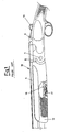
- figure 1 is a partial section side elevation view of a piece of a central part of a closed rifle according to the prior art with the iron fore-end forced upon the action body,
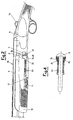
- figure 2 is a side elevation view of a central part of a rifle according to the invention, in partial section and with the barrels closed,
- figure 3 is a side elevation view, similar to the one in figure 2, where the rifle according to the invention has the barrels open, and
- figure 4 is a plan view of the iron fore-end carrying the device.
- For a better understanding of the invention we refer to the quoted figures 2, 3 and 4 in which a barrel balancing device for collapsible firearms is shown, in particular showing a rifle with a single bore or with two over-and-under barrels.
- The invention proposes that the balancing torque no longer be realised by means of the iron fore-end/action body forcing and the consequent contact friction, but rather by the action of an active balancing force, such as to generate an equal and opposite action to that of the weight force.
- In particular, the invention can be seen clearly from the figures, in which the elements similar or corresponding to those of the prior art are indicated with the same reference numerals as the previous figure 1.
- It should therefore be noted in the example shown that in a
collapsible rifle 20, it is proposed to realise balancing forces capable of creating a counter torque to counteract that generated by the weight force. In particular this is obtained in the example through an elastic group which foresees two balancers, right 24 and left 25,relative spring guides 22 andsprings 23. In the example the various elements are in pairs but a single arrangement of suitable force could be foreseen. As an alternative to the elastic group described above, it is conceivable to use any other elastic or viscoelastic system, i.e. a viscous characteristic which counteracts the falling motion of the barrel and a position-recovery elastic function. - Such forces, coming from the compression of the
spring guides 22 bysuitable push rods 21, mounted on theaction body 6, act directly on the iron fore-end 8 and therefore, through thetenon 10, on thebarrel group 9, according to a line of action which is suitably misaligned with respect to the axis of thehinge pin 7, consequently being in opposition with respect to the weight force. More precisely, thepush rods 21 act uponcam surfaces 26 formed at the rear of the right 24 and/or left 25 balancers. In particular, thebalancers barrels 9. - It should also be noted that such balancers, relative springs and spring guide are integrated in the structure of the fore-end 12 (although this is not necessarily so since it is just as practicable to integrate them on the side of the action body), according to the diagram shown in figures 2, 3 and 4 so as to be completely hidden from view with the rifle assembled.
- The
balancers end 8 through suitable slits of a height proportional to the rotary stroke of thebarrel 9, with the pushingsurface 26 facing towards thecounter push rods 21. - The different ways of operating with respect to the conventional system (active balancing force against passive friction force) reduces the iron fore-end/action body contact pressure to very low levels. Purely for indicating purposes, and in any case dependent upon the lever arms and the mass of the barrel group, the force needed for each of the two springs can be set at about 20 kg.
- Consequently, the device of the invention does not put up any appreciably large passive resistance, i.e. friction, to the closing of the barrels. In fact, an at least partial self-closing effect can be realised. Moreover, the problem of possible seizures due to excessive contact forces is solved. The wear from contact between
push rods 21 andbalancers - The balancing effect is influenced little by the arming of the battery since the force of the
springs 23 is substantially stronger with respect to that of the ejection hammer springs (not shown). The calibration of the device, relative to the balancing effect, is realised in the intermediate condition by a single unloaded ejection hammer. - A suitable sizing of the balancers, for example a special angulation of the contact surface with the push rods, so as to create suitable misalignments of the balancing force according to the opening angle of the barrel, allows the characteristic balancing curve to be optimised, as well as the use of special elastic elements such as variable pitch springs, progressive springs, etc. For example, a change in the inclination in the last degrees of the work stroke of the balancers allows a stop position at the end of the opening stroke of the barrels themselves to be obtained by inverting the arm of the balancing force with respect to the centre of rotation of the barrel.
- Another, highly desirable advantage of the invention consists, once the fore-
end iron catch 11 is freed, of the ease of dismantling of the fore-end, an advantage gained as a consequence of the extremely low forcing, limited to the force applied by the springs, of the iron fore-end between barrel tenon and action body. - Advantageously, by foreseeing a device according to the invention, it is possible to use alternative materials for the iron fore-end, such as light alloys, to gain a saving in terms of treatment costs and weights.
- It is clear that a device according to the invention can be mounted on a firearm with collapsible barrel(s), i.e. wherein the opening of the firearm is realised by rotation of the barrel (or barrels) with respect to the breech (or action body) plane, without a limitation regarding the type of firearm which can be of the type used for sport (for example an over-and-under, side-by-side or single-bore rifle, in this case even with semiautomatic operation), with a smooth or rifled bore.
- It is equally clear that the barrel or the barrel group, possibly equipped with targeting sight members, is mobile by rotation with respect to a fixed hinging point arranged on a breech or action body.
- The barrel or the barrel group according to the invention has its centre of gravity in a misaligned position with respect to the hinging point so as to create an unbalancing torque tending to make it fall spontaneously once the closing device or top lever is unlocked.
- A device according to the invention thus achieves all of its purposes.
- A barrel balancing device for firearms of the present invention thus conceived is susceptible to numerous modifications and variants, all covered by the invention itself.
- Moreover, in practice the materials used, as well as their sizes and the components, can be whatever according to the technical requirements.
Claims (11)
- Barrel balancing device for collapsible firearms (20) wherein at least one barrel (9) which is mobile for rotation about a fixed hinging point (7) arranged on an action body (6) is foreseen, wherein an open-close top lever (13) is foreseen between a closed aligned position of said at least one barrel (9) and said action body (6), and a position disengaged and rotated upon opening of said at least one barrel (9) with respect to said action body (6), said at least one barrel (9) being carried by an iron fore-end (8), characterised in that it foresees at least one elastic or viscoelastic group (21, 22, 23, 24, 25, 26) which interacts between said iron fore-end and said action body (6) to oppose the falling motion of said at least one barrel (9), once said open-close top lever (13) is unlocked, and to realise a balancing push with respect to the weight of said at least one barrel (9) when said collapsible firearm (20) is closed.
- Device according to claim 1, characterised in that said at least one elastic or viscoelastic group comprises on the one hand at least one balancer (24, 25), at least one spring guide (22) and at least one spring (23) arranged on it, said at least one spring guide (22) being in engagement on the other side with said at least one balancer (24, 25).
- Device according to claim 2, characterised in that said iron fore-end (8) is arranged on one side and said action body (6) is arranged on the other.
- Device according to claim 2, characterised in that said at least one push rod (21) acts according to a line of action which is misaligned with respect to said hinging point (7).
- Device according to claim 2, characterised in that said at least one push rod (21) acts upon a cam surface (26) formed on the rear of said at least one balancer (24, 25).
- Device according to claim 2, characterised in that said at least one balancer (24, 25), at least one spring guide (22) and at least one spring (23) are integrated in the structure of a fore-end (12) of said firearm.
- Device according to claim 2, characterised in that said at least one balancer (24, 25) comes out from the body of said iron fore-end (8) through slits of a height proportional to the rotary stroke of said barrel (9).
- Device according to claim 2, characterised in that said at least one balancer (24, 25) has an optimised profile so as to realise a perfect balancing or an at least partial self-closing effect according to the opening angle and a stop function at the end of the opening stroke of said barrel (9).
- Device according to claim 2, characterised in that said at least one barrel (9) is equipped with a targeting system.
- Device according to claim 2, characterised in that said at least one barrel (9) has the centre of gravity in misaligned position with respect to said hinging point (7) so as to create an unbalancing torque tending to make it fall spontaneously once said open-close top lever (13) is unlocked.
- Device according to claim 1, characterised in that said iron fore-end (8) has a shaped end surface placed in rotary engagement with a matching end surface facing said action body (6).
Applications Claiming Priority (2)
| Application Number | Priority Date | Filing Date | Title |
|---|---|---|---|
| IT2001MI002400A ITMI20012400A1 (en) | 2001-11-14 | 2001-11-14 | BARREL BALANCING DEVICE FOR TILTING WEAPONS |
| ITMI20012400 | 2001-11-14 |
Publications (2)
| Publication Number | Publication Date |
|---|---|
| EP1312887A1 EP1312887A1 (en) | 2003-05-21 |
| EP1312887B1 true EP1312887B1 (en) | 2004-12-15 |
Family
ID=11448602
Family Applications (1)
| Application Number | Title | Priority Date | Filing Date |
|---|---|---|---|
| EP02079651A Expired - Lifetime EP1312887B1 (en) | 2001-11-14 | 2002-11-07 | Barrel balancing device for collapsible firearms |
Country Status (8)
| Country | Link |
|---|---|
| US (1) | US6705035B2 (en) |
| EP (1) | EP1312887B1 (en) |
| JP (1) | JP2003148896A (en) |
| AT (1) | ATE285061T1 (en) |
| CA (1) | CA2411674A1 (en) |
| DE (1) | DE60202252T2 (en) |
| ES (1) | ES2233770T3 (en) |
| IT (1) | ITMI20012400A1 (en) |
Families Citing this family (13)
| Publication number | Priority date | Publication date | Assignee | Title |
|---|---|---|---|---|
| ITMI970419A1 (en) * | 1997-02-26 | 1998-08-27 | Franchi S P A | HUNTED RIFLE OVERLAPPING WITH DEVICE FOR THE INTERCHANGEABILITY OF THE SERIES OF THE ROD GROUP |
| ITMI20041892A1 (en) * | 2004-10-06 | 2005-01-06 | Beretta Armi Spa | DRAW ADJUSTMENT DEVICE BETWEEN THE CROSS AND BASE IN A TILTING WEAPON |
| GR20070100038A (en) * | 2007-01-23 | 2008-09-04 | Χρηστος Νικολαου Σωτηροπουλος | Electrically-driven opening of articulated weapons. |
| ITMI20070106A1 (en) * | 2007-01-24 | 2008-07-25 | Beretta Armi Spa | SEMI-AUTOMATIC RIFULOUS RIFLE |
| US9057574B2 (en) | 2012-06-14 | 2015-06-16 | Ra Brands, L.L.C. | Thumb safety for model 1911 handgun |
| US8950387B2 (en) * | 2013-01-25 | 2015-02-10 | Kee Action Sports I Llc | Paintball marker with split body |
| CN103424031A (en) * | 2013-07-18 | 2013-12-04 | 重庆建设工业(集团)有限责任公司 | Gunstock folding mechanism |
| USD840493S1 (en) | 2017-03-10 | 2019-02-12 | AIM Sports Inc. | Collapsible pin for firearm stocks |
| WO2019130102A1 (en) * | 2017-12-29 | 2019-07-04 | Caesar Guerini S.R.L. | Firearm |
| US10627187B1 (en) * | 2018-10-30 | 2020-04-21 | Kuan Ting Lin | Shooting controller of paintball gun |
| US10704859B2 (en) | 2018-11-06 | 2020-07-07 | Gi Sportz Direct Llc | Compressed gas gun front grip having battery access panel |
| CN113758370A (en) * | 2021-08-25 | 2021-12-07 | 浙江新华机械制造有限公司 | Non-lethal emitter |
| US12332014B2 (en) | 2022-09-08 | 2025-06-17 | Kore Outdoor (Us) Inc. | Foldable break barrel airgun |
Family Cites Families (23)
| Publication number | Priority date | Publication date | Assignee | Title |
|---|---|---|---|---|
| US804349A (en) * | 1905-04-24 | 1905-11-14 | Karl Friedrich Philipp Stendebach | Firearm with drop-down barrel. |
| BE378896A (en) * | 1930-04-14 | |||
| US3053878A (en) * | 1961-05-23 | 1962-09-11 | Weston Chemical Corp | Pentaerythritol phosphite esters |
| US3662032A (en) * | 1961-12-18 | 1972-05-09 | Argus Chem | Hydroxy containing aromatic phosphites |
| US3476699A (en) * | 1961-12-18 | 1969-11-04 | Argus Chem | Polyvinyl chloride and olefin polymer compositions having improved resistance to deterioration comprising an organic phosphite ester having at least one aromatic polycarbocyclic group |
| NL298956A (en) * | 1962-10-08 | |||
| US3305520A (en) * | 1965-04-06 | 1967-02-21 | Bayer Ag | Polycarbonates stabilized by phosphites |
| US4290976A (en) * | 1975-03-24 | 1981-09-22 | Borg-Warner Chemicals, Inc. | Process for the preparation of phenol-free phosphites |
| NL7506988A (en) * | 1975-06-12 | 1976-12-14 | Akzo Nv | ORGANIC TRIPHOSCYCLES WITH IMPROVED HYDROLYTIC STABILITY. |
| CA1068893A (en) * | 1975-08-11 | 1980-01-01 | Borg-Warner Corporation | Stabilizer for vinyl polymers |
| CA1078862A (en) * | 1976-03-04 | 1980-06-03 | James F. York | Preparation of organic phosphites |
| DE2715589A1 (en) * | 1976-04-14 | 1977-10-27 | Ciba Geigy Ag | NEW PHENOL STABILIZERS |
| US4094999A (en) * | 1977-08-08 | 1978-06-13 | Borg-Warner Corporation | Antioxidant for foods |
| US4156980A (en) * | 1978-01-20 | 1979-06-05 | Aspenwall John E | Breech opening apparatus for handgun |
| SE430435B (en) * | 1981-12-14 | 1983-11-14 | Flodman Guns Kb | GUIDANCE FOR A SWITCH |
| US4650894A (en) * | 1984-07-05 | 1987-03-17 | Argus Chemical Corporation | Tris-organophosphite compositions having improved hydrolytic stability |
| US5290747A (en) * | 1992-09-18 | 1994-03-01 | Industrial Technology Research Institute | Nylon 6 catalyst system |
| US5364895A (en) * | 1993-01-20 | 1994-11-15 | Dover Chemical Corp. | Hydrolytically stable pentaerythritol diphosphites |
| US5469649A (en) | 1993-12-30 | 1995-11-28 | Remington Arms Company, Inc. | Firearm top lever adjusting system |
| US5532401A (en) * | 1995-01-19 | 1996-07-02 | Dover Chemical Corporation | Process for production of tris(nonylphenyl) phosphite |
| JP3065246B2 (en) * | 1995-03-10 | 2000-07-17 | 富士化学工業株式会社 | Stabilizer for halogen-containing resin, method for producing the same, and halogen-containing resin composition |
| DE69602416T2 (en) * | 1995-06-23 | 1999-09-09 | Fuji Chemical Industry Co. | NEW COMPOSITE OF HYDROXIDE / CONDENSED SILICATES, METHOD FOR THE PRODUCTION THEREOF, INFRARED ABSORBER AND AGRICULTURAL FILM |
| AT412173B (en) * | 1997-02-25 | 2004-10-25 | Holzinger Wolfgang | CLIPS WITH BLOCKING CLOSURE |
-
2001
- 2001-11-14 IT IT2001MI002400A patent/ITMI20012400A1/en unknown
-
2002
- 2002-11-07 AT AT02079651T patent/ATE285061T1/en not_active IP Right Cessation
- 2002-11-07 DE DE60202252T patent/DE60202252T2/en not_active Expired - Fee Related
- 2002-11-07 EP EP02079651A patent/EP1312887B1/en not_active Expired - Lifetime
- 2002-11-07 ES ES02079651T patent/ES2233770T3/en not_active Expired - Lifetime
- 2002-11-07 US US10/289,783 patent/US6705035B2/en not_active Expired - Lifetime
- 2002-11-12 CA CA002411674A patent/CA2411674A1/en not_active Abandoned
- 2002-11-14 JP JP2002331189A patent/JP2003148896A/en not_active Ceased
Also Published As
| Publication number | Publication date |
|---|---|
| DE60202252T2 (en) | 2005-12-08 |
| US20030089015A1 (en) | 2003-05-15 |
| ITMI20012400A1 (en) | 2003-05-14 |
| EP1312887A1 (en) | 2003-05-21 |
| DE60202252D1 (en) | 2005-01-20 |
| ES2233770T3 (en) | 2005-06-16 |
| JP2003148896A (en) | 2003-05-21 |
| CA2411674A1 (en) | 2003-05-14 |
| US6705035B2 (en) | 2004-03-16 |
| ATE285061T1 (en) | 2005-01-15 |
Similar Documents
| Publication | Publication Date | Title |
|---|---|---|
| US6705035B2 (en) | Barrel balancing device for collapsible firearms | |
| CA2675219C (en) | Control element, firing unit and firing assembly for a weapon | |
| US10330432B2 (en) | Adjustable firearm stock | |
| US7162822B1 (en) | Collapsible buttstock for firearm | |
| US20160033218A1 (en) | Semiautomatic firearm | |
| US8074393B2 (en) | Adjustable dual stage trigger mechanism for semi-automatic weapons | |
| CA2347422C (en) | Hammer release apparatus | |
| US20080289238A1 (en) | Barrel link for a semiautomatic weapon | |
| US20170241729A1 (en) | Bolt Catch for a Rifle | |
| EP1914504B1 (en) | Mechanism for locking and adjusting the assembly tension of the stock to a receiver of a firearm | |
| US20190093984A1 (en) | Adjusting device for an adjustable rest for a rifle stock | |
| US20080022576A1 (en) | Octagonal Scope and Ring Mount | |
| US5225610A (en) | One-shot weapons | |
| US11029116B2 (en) | Trigger mechanism for firearms | |
| IL273357B2 (en) | Unholstered weapon (variables) | |
| US10641562B2 (en) | Firearm with recoil mitigation | |
| EP3901559B1 (en) | Conversion kit for assault rifles | |
| CA2622311A1 (en) | Gas cylinder part and small arms weapon | |
| CZ2017561A3 (en) | A rebound shock absorbing mechanism for a firearm | |
| US10228214B1 (en) | Fixed stock adapter | |
| US20230056193A1 (en) | Pistol | |
| US20100229446A1 (en) | Break-action firearm and trigger mechanism | |
| US20170307314A1 (en) | Modified break-action firearm | |
| US4301712A (en) | Device for controlling the degree of blowback delay in automatic weapons | |
| US20100037760A1 (en) | Method and apparatus for muzzle lift compensation |
Legal Events
| Date | Code | Title | Description |
|---|---|---|---|
| PUAI | Public reference made under article 153(3) epc to a published international application that has entered the european phase |
Free format text: ORIGINAL CODE: 0009012 |
|
| AK | Designated contracting states |
Designated state(s): AT BE BG CH CY CZ DE DK EE ES FI FR GB GR IE IT LI LU MC NL PT SE SK TR |
|
| AX | Request for extension of the european patent |
Extension state: AL LT LV MK RO SI |
|
| 17P | Request for examination filed |
Effective date: 20031027 |
|
| AKX | Designation fees paid |
Designated state(s): AT BE BG CH CY CZ DE DK EE ES FI FR GB GR IE IT LI LU MC NL PT SE SK TR |
|
| GRAP | Despatch of communication of intention to grant a patent |
Free format text: ORIGINAL CODE: EPIDOSNIGR1 |
|
| GRAS | Grant fee paid |
Free format text: ORIGINAL CODE: EPIDOSNIGR3 |
|
| GRAA | (expected) grant |
Free format text: ORIGINAL CODE: 0009210 |
|
| AK | Designated contracting states |
Kind code of ref document: B1 Designated state(s): AT BE BG CH CY CZ DE DK EE ES FI FR GB GR IE IT LI LU MC NL PT SE SK TR |
|
| PG25 | Lapsed in a contracting state [announced via postgrant information from national office to epo] |
Ref country code: NL Free format text: LAPSE BECAUSE OF FAILURE TO SUBMIT A TRANSLATION OF THE DESCRIPTION OR TO PAY THE FEE WITHIN THE PRESCRIBED TIME-LIMIT Effective date: 20041215 Ref country code: CH Free format text: LAPSE BECAUSE OF FAILURE TO SUBMIT A TRANSLATION OF THE DESCRIPTION OR TO PAY THE FEE WITHIN THE PRESCRIBED TIME-LIMIT Effective date: 20041215 Ref country code: LI Free format text: LAPSE BECAUSE OF FAILURE TO SUBMIT A TRANSLATION OF THE DESCRIPTION OR TO PAY THE FEE WITHIN THE PRESCRIBED TIME-LIMIT Effective date: 20041215 Ref country code: BG Free format text: LAPSE BECAUSE OF FAILURE TO SUBMIT A TRANSLATION OF THE DESCRIPTION OR TO PAY THE FEE WITHIN THE PRESCRIBED TIME-LIMIT Effective date: 20041215 Ref country code: CZ Free format text: LAPSE BECAUSE OF FAILURE TO SUBMIT A TRANSLATION OF THE DESCRIPTION OR TO PAY THE FEE WITHIN THE PRESCRIBED TIME-LIMIT Effective date: 20041215 Ref country code: FI Free format text: LAPSE BECAUSE OF FAILURE TO SUBMIT A TRANSLATION OF THE DESCRIPTION OR TO PAY THE FEE WITHIN THE PRESCRIBED TIME-LIMIT Effective date: 20041215 Ref country code: AT Free format text: LAPSE BECAUSE OF FAILURE TO SUBMIT A TRANSLATION OF THE DESCRIPTION OR TO PAY THE FEE WITHIN THE PRESCRIBED TIME-LIMIT Effective date: 20041215 Ref country code: EE Free format text: LAPSE BECAUSE OF FAILURE TO SUBMIT A TRANSLATION OF THE DESCRIPTION OR TO PAY THE FEE WITHIN THE PRESCRIBED TIME-LIMIT Effective date: 20041215 Ref country code: SK Free format text: LAPSE BECAUSE OF FAILURE TO SUBMIT A TRANSLATION OF THE DESCRIPTION OR TO PAY THE FEE WITHIN THE PRESCRIBED TIME-LIMIT Effective date: 20041215 |
|
| REG | Reference to a national code |
Ref country code: CH Ref legal event code: EP Ref country code: GB Ref legal event code: FG4D |
|
| REG | Reference to a national code |
Ref country code: IE Ref legal event code: FG4D |
|
| REF | Corresponds to: |
Ref document number: 60202252 Country of ref document: DE Date of ref document: 20050120 Kind code of ref document: P |
|
| PG25 | Lapsed in a contracting state [announced via postgrant information from national office to epo] |
Ref country code: DK Free format text: LAPSE BECAUSE OF FAILURE TO SUBMIT A TRANSLATION OF THE DESCRIPTION OR TO PAY THE FEE WITHIN THE PRESCRIBED TIME-LIMIT Effective date: 20050315 Ref country code: SE Free format text: LAPSE BECAUSE OF FAILURE TO SUBMIT A TRANSLATION OF THE DESCRIPTION OR TO PAY THE FEE WITHIN THE PRESCRIBED TIME-LIMIT Effective date: 20050315 |
|
| REG | Reference to a national code |
Ref country code: GR Ref legal event code: EP Ref document number: 20050400686 Country of ref document: GR |
|
| NLV1 | Nl: lapsed or annulled due to failure to fulfill the requirements of art. 29p and 29m of the patents act | ||
| REG | Reference to a national code |
Ref country code: ES Ref legal event code: FG2A Ref document number: 2233770 Country of ref document: ES Kind code of ref document: T3 |
|
| REG | Reference to a national code |
Ref country code: CH Ref legal event code: PL |
|
| PLBE | No opposition filed within time limit |
Free format text: ORIGINAL CODE: 0009261 |
|
| STAA | Information on the status of an ep patent application or granted ep patent |
Free format text: STATUS: NO OPPOSITION FILED WITHIN TIME LIMIT |
|
| PG25 | Lapsed in a contracting state [announced via postgrant information from national office to epo] |
Ref country code: IE Free format text: LAPSE BECAUSE OF NON-PAYMENT OF DUE FEES Effective date: 20051107 Ref country code: CY Free format text: LAPSE BECAUSE OF FAILURE TO SUBMIT A TRANSLATION OF THE DESCRIPTION OR TO PAY THE FEE WITHIN THE PRESCRIBED TIME-LIMIT Effective date: 20051107 |
|
| PG25 | Lapsed in a contracting state [announced via postgrant information from national office to epo] |
Ref country code: LU Free format text: LAPSE BECAUSE OF NON-PAYMENT OF DUE FEES Effective date: 20051130 Ref country code: MC Free format text: LAPSE BECAUSE OF NON-PAYMENT OF DUE FEES Effective date: 20051130 |
|
| 26N | No opposition filed |
Effective date: 20050916 |
|
| ET | Fr: translation filed | ||
| REG | Reference to a national code |
Ref country code: IE Ref legal event code: MM4A |
|
| PG25 | Lapsed in a contracting state [announced via postgrant information from national office to epo] |
Ref country code: PT Free format text: LAPSE BECAUSE OF NON-PAYMENT OF DUE FEES Effective date: 20050515 |
|
| PGFP | Annual fee paid to national office [announced via postgrant information from national office to epo] |
Ref country code: DE Payment date: 20081103 Year of fee payment: 7 |
|
| PGFP | Annual fee paid to national office [announced via postgrant information from national office to epo] |
Ref country code: FR Payment date: 20081112 Year of fee payment: 7 |
|
| PGFP | Annual fee paid to national office [announced via postgrant information from national office to epo] |
Ref country code: GR Payment date: 20081016 Year of fee payment: 7 |
|
| PGFP | Annual fee paid to national office [announced via postgrant information from national office to epo] |
Ref country code: TR Payment date: 20091014 Year of fee payment: 8 |
|
| REG | Reference to a national code |
Ref country code: FR Ref legal event code: ST Effective date: 20100730 |
|
| PG25 | Lapsed in a contracting state [announced via postgrant information from national office to epo] |
Ref country code: FR Free format text: LAPSE BECAUSE OF NON-PAYMENT OF DUE FEES Effective date: 20091130 Ref country code: GR Free format text: LAPSE BECAUSE OF NON-PAYMENT OF DUE FEES Effective date: 20100602 |
|
| PG25 | Lapsed in a contracting state [announced via postgrant information from national office to epo] |
Ref country code: DE Free format text: LAPSE BECAUSE OF NON-PAYMENT OF DUE FEES Effective date: 20100601 |
|
| PGFP | Annual fee paid to national office [announced via postgrant information from national office to epo] |
Ref country code: ES Payment date: 20101217 Year of fee payment: 9 |
|
| PG25 | Lapsed in a contracting state [announced via postgrant information from national office to epo] |
Ref country code: TR Free format text: LAPSE BECAUSE OF NON-PAYMENT OF DUE FEES Effective date: 20101107 |
|
| REG | Reference to a national code |
Ref country code: ES Ref legal event code: FD2A Effective date: 20130604 |
|
| PG25 | Lapsed in a contracting state [announced via postgrant information from national office to epo] |
Ref country code: ES Free format text: LAPSE BECAUSE OF NON-PAYMENT OF DUE FEES Effective date: 20111108 |
|
| PGFP | Annual fee paid to national office [announced via postgrant information from national office to epo] |
Ref country code: GB Payment date: 20201028 Year of fee payment: 19 Ref country code: IT Payment date: 20201110 Year of fee payment: 19 |
|
| PGFP | Annual fee paid to national office [announced via postgrant information from national office to epo] |
Ref country code: BE Payment date: 20201015 Year of fee payment: 19 |
|
| GBPC | Gb: european patent ceased through non-payment of renewal fee |
Effective date: 20211107 |
|
| PG25 | Lapsed in a contracting state [announced via postgrant information from national office to epo] |
Ref country code: BE Free format text: LAPSE BECAUSE OF NON-PAYMENT OF DUE FEES Effective date: 20211130 |
|
| REG | Reference to a national code |
Ref country code: BE Ref legal event code: MM Effective date: 20211130 |
|
| PG25 | Lapsed in a contracting state [announced via postgrant information from national office to epo] |
Ref country code: GB Free format text: LAPSE BECAUSE OF NON-PAYMENT OF DUE FEES Effective date: 20211107 |
|
| PG25 | Lapsed in a contracting state [announced via postgrant information from national office to epo] |
Ref country code: IT Free format text: LAPSE BECAUSE OF NON-PAYMENT OF DUE FEES Effective date: 20211107 |